JP2020121479A - Injection mold - Google Patents
Injection mold Download PDFInfo
- Publication number
- JP2020121479A JP2020121479A JP2019014673A JP2019014673A JP2020121479A JP 2020121479 A JP2020121479 A JP 2020121479A JP 2019014673 A JP2019014673 A JP 2019014673A JP 2019014673 A JP2019014673 A JP 2019014673A JP 2020121479 A JP2020121479 A JP 2020121479A
- Authority
- JP
- Japan
- Prior art keywords
- runner
- gates
- injection
- resin
- flow path
- Prior art date
- Legal status (The legal status is an assumption and is not a legal conclusion. Google has not performed a legal analysis and makes no representation as to the accuracy of the status listed.)
- Pending
Links
- 238000002347 injection Methods 0.000 title claims abstract description 160
- 239000007924 injection Substances 0.000 title claims abstract description 160
- 239000011347 resin Substances 0.000 claims abstract description 216
- 229920005989 resin Polymers 0.000 claims abstract description 216
- 238000000465 moulding Methods 0.000 claims description 100
- 238000011144 upstream manufacturing Methods 0.000 claims description 17
- 230000007423 decrease Effects 0.000 claims description 5
- 238000004891 communication Methods 0.000 claims description 3
- 239000000243 solution Substances 0.000 abstract 1
- 238000001746 injection moulding Methods 0.000 description 79
- 230000002093 peripheral effect Effects 0.000 description 18
- 238000004519 manufacturing process Methods 0.000 description 9
- 238000005452 bending Methods 0.000 description 5
- 239000000463 material Substances 0.000 description 5
- 230000000052 comparative effect Effects 0.000 description 3
- 230000000694 effects Effects 0.000 description 2
- 238000000034 method Methods 0.000 description 2
- 238000004088 simulation Methods 0.000 description 2
- 241001272720 Medialuna californiensis Species 0.000 description 1
- 102220477328 Protein XRP2_R32A_mutation Human genes 0.000 description 1
- 238000007792 addition Methods 0.000 description 1
- 230000015572 biosynthetic process Effects 0.000 description 1
- 238000009826 distribution Methods 0.000 description 1
- 229920001971 elastomer Polymers 0.000 description 1
- 239000000806 elastomer Substances 0.000 description 1
- 230000009477 glass transition Effects 0.000 description 1
- 238000003754 machining Methods 0.000 description 1
- 239000002184 metal Substances 0.000 description 1
- 238000000926 separation method Methods 0.000 description 1
- 239000007787 solid Substances 0.000 description 1
- 238000006467 substitution reaction Methods 0.000 description 1
Images





Landscapes
- Moulds For Moulding Plastics Or The Like (AREA)
Abstract
Description
本発明は、射出成形金型に関する。 The present invention relates to an injection mold.
複数のゲートを用いる射出成形では、各ゲートからの樹脂の入り方が、成形空間において略均等であることが好ましい。成形空間に充填される樹脂のバランスがくずれると、良好な成形が行えないおそれがある。
複数のゲートを用いる射出成形では、射出樹脂が分岐流路を有するランナーを通して、各ゲートに分流される。特許文献1には、分岐流路における各流路の長さを互いに等しくすることによって各ゲートへの射出樹脂の到達時間を均等化する技術が提案されている。
In injection molding using a plurality of gates, it is preferable that the resin enters from each gate substantially uniformly in the molding space. If the balance of the resin filled in the molding space is lost, good molding may not be performed.
In injection molding using a plurality of gates, the injection resin is divided into each gate through a runner having a branch flow path.
しかしながら、上記のような関連技術には、以下のような問題がある。
特許文献1に記載の技術では、分離流路への樹脂注入口からゲートまでの距離によらず、分岐流路の長さを互いに等しくする目的で、樹脂注入口から近いゲートまでの流路が湾曲されている。
しかし、金型において湾曲した流路を形成できるスペースは限られている。流路のスペースが不足する場合には、金型を大型化しなければならないという問題がある。この場合、金型コストが増大する。さらに、ランナーの長さが長くなるので樹脂の消費量も増える。
金型の大型化を避ける目的で、ランナーを湾曲させてランナーの長さを確保することも考えられるが、この場合、金型の加工が複雑になるので金型の製造コストが増大してしまう。
例えば、長尺の成形品において軸方向にゲートを配列する場合、樹脂注入口から各ゲートへの最短距離のバラツキが格段に大きい。樹脂注入口から近いゲートほど、狭い領域に長い流路を収める必要がある。さらに、より遠くのゲートに向かう流路は、より近くにおいて湾曲した流路を避けて形成される必要があるので、より遠くのゲートに向かう流路も湾曲させる必要が生じる。この結果、各流路の長さがそれぞれ延びるので、特に金型が大型化しやすい。
However, the related art as described above has the following problems.
In the technique described in
However, the space in which a curved flow path can be formed in the mold is limited. When the space of the flow path is insufficient, there is a problem that the mold has to be upsized. In this case, the die cost increases. In addition, the length of the runner increases, so the amount of resin consumed also increases.
It may be possible to bend the runner to secure the length of the runner for the purpose of avoiding the enlargement of the mold, but in this case, the machining of the mold becomes complicated and the manufacturing cost of the mold increases. ..
For example, when arranging the gates in the axial direction in a long molded product, the variation in the shortest distance from the resin injection port to each gate is significantly large. The closer the gate is to the resin injection port, the longer the flow path needs to be accommodated in the narrow region. Further, since the flow path toward the farther gate needs to be formed so as to avoid the curved flow path closer to the gate, the flow path toward the farther gate also needs to be curved. As a result, the length of each flow path is increased, so that the size of the mold is likely to increase.
本発明は、上記のような問題に鑑みてなされたものであり、射出樹脂を複数のゲートに均等に分流することができ、小型化可能な射出成形金型を提供することを目的とする。 The present invention has been made in view of the above problems, and an object of the present invention is to provide an injection molding die that can evenly divide an injection resin into a plurality of gates and can be downsized.
上記の課題を解決するために、本発明の第1の態様の射出成形金型は、射出樹脂が注入される注入口を有する上流ランナーと、前記射出樹脂に表面形状を転写する成形面と、前記成形面において開口する複数のゲートと、前記上流ランナーおよび前記複数のゲートにそれぞれ連通し、前記注入口に注入された前記射出樹脂を前記複数のゲートのそれぞれに分流する下流ランナーと、を含み、前記下流ランナーは、前記注入口に注入された前記射出樹脂が流入する開口と、第1内径を有する第1円管状流路と、を有しており、前記開口は前記第1円管状流路に開口しており、前記第1円管状流路は前記複数のゲートに面し前記複数のゲートの並びに沿って延びている第1ランナー部と、前記第1ランナー部と前記複数のゲートのそれぞれとに連通しており、前記第1ランナー部よりも高抵抗の流路断面を有することによって前記開口から前記複数のゲートのそれぞれへの到達時間を均等化する第2ランナー部と、を含む。 In order to solve the above problems, the injection mold of the first aspect of the present invention is an upstream runner having an injection port into which an injection resin is injected, a molding surface for transferring a surface shape to the injection resin, A plurality of gates that open in the molding surface, and a downstream runner that communicates with the upstream runner and the plurality of gates, respectively, and divides the injection resin injected into the injection port into each of the plurality of gates. The downstream runner has an opening through which the injection resin injected into the injection port flows, and a first circular tubular flow path having a first inner diameter, and the opening is the first circular tubular flow path. A first runner portion that is open to the passage, the first circular tubular flow path faces the plurality of gates, and extends along the row of the plurality of gates; and the first runner portion and the plurality of gates. A second runner portion that communicates with each of the first runner portions and that has a flow passage cross section having a resistance higher than that of the first runner portion to equalize the arrival time from the opening to each of the plurality of gates. ..
上記射出成形金型において、前記第2ランナー部は、前記第1ランナー部に開口するスリットを有する板状流路を含み、前記スリットの大きさおよび前記板状流路における厚さ方向の流路幅は、前記第1内径よりも小さくてもよい。 In the injection molding die, the second runner portion includes a plate-like flow path having a slit that opens to the first runner portion, and the size of the slit and the flow path in the thickness direction of the plate-like flow path. The width may be smaller than the first inner diameter.
上記射出成形金型において、前記下流ランナーは、前記第2ランナー部と前記複数のゲートのそれぞれとに連通し、前記第2ランナー部よりも低抵抗の流路断面を有する第2円管状流路を有する第3ランナー部をさらに含んでもよい。 In the injection-molding die, the downstream runner communicates with the second runner portion and each of the plurality of gates, and has a second circular tubular flow passage having a flow passage cross section having a lower resistance than the second runner portion. You may further include the 3rd runner part which has.
上記射出成形金型において、前記開口は、前記第1円管状流路の延在方向における中間部に形成されており、前記第1円管状流路は、前記延在方向において前記中間部から離れるにつれて、前記複数のゲートに対する対面方向において、前記第1円管状流路は前記複数のゲートに近づく凹状に湾曲していてもよい。 In the injection molding die, the opening is formed at an intermediate portion in the extending direction of the first circular tubular flow passage, and the first circular tubular flow passage is separated from the intermediate portion in the extending direction. Accordingly, in the facing direction with respect to the plurality of gates, the first circular tubular flow path may be curved in a concave shape approaching the plurality of gates.
上記射出成形金型において、前記開口は、前記第1円管状流路の延在方向における中間部に形成されており、前記複数のゲートに対する対面方向における前記第2ランナー部の長さが、前記延在方向において前記中間部から離れるにつれて短くなっていてもよい。 In the injection molding die, the opening is formed at an intermediate portion in the extending direction of the first circular tubular flow path, and the length of the second runner portion in the facing direction with respect to the plurality of gates is It may become shorter as it goes away from the intermediate portion in the extending direction.
上記射出成形金型において、前記開口は、前記第1円管状流路の延在方向における中間部に形成されており、前記大きさおよび前記流路幅が、前記延在方向において前記中間部から離れるにつれて大きくなっていてもよい。 In the injection molding die, the opening is formed in an intermediate portion in the extending direction of the first circular tubular flow passage, and the size and the flow passage width are from the intermediate portion in the extending direction. It may grow larger with distance.
上記射出成形金型において、前記開口は、前記第1円管状流路の延在方向における第1端部に形成されており、前記第1円管状流路は、前記第1円管状流路と前記複数のゲートの並びと間の距離が、前記第1端部から前記第1端部と反対側の第2端部に向かって減少するように配置されており、前記第2ランナー部の長さは、前記延在方向において前記第1端部から離れるにつれて短くなっていてもよい。 In the injection molding die, the opening is formed at a first end portion in the extending direction of the first circular tubular flow channel, and the first circular tubular flow channel is the first circular tubular flow channel. The distance between the rows of the plurality of gates is arranged so as to decrease from the first end toward a second end opposite to the first end, and the length of the second runner part is reduced. The length may become shorter as the distance from the first end portion increases in the extending direction.
本発明の第2の態様の射出成形金型は、射出樹脂が注入される注入口を有する上流ランナーと、前記射出樹脂に表面形状を転写する成形面と、前記成形面において開口する複数のゲートと、前記上流ランナーおよび前記複数のゲートにそれぞれ連通し、前記注入口に注入された前記射出樹脂を前記複数のゲートのそれぞれに分流する下流ランナーと、を備え、前記下流ランナーは、前記注入口に注入された前記射出樹脂が流入する開口と、第1内径を有する第1円管状流路と、を有しており、前記開口は前記第1円管状流路に開口しており、前記第1円管状流路は前記複数のゲートに面し前記複数のゲートの並びに沿って延びている第1ランナー部と、前記第1ランナー部と前記複数のゲートのそれぞれとに連通しており、前記第1ランナー部よりも高抵抗の流路断面を有し、前記第1ランナーから前記複数のゲートに向かうそれぞれの最短距離が前記開口から前記複数のゲートまでのそれぞれの最短距離によって異なる第2ランナー部と、を含む。 The injection molding die according to the second aspect of the present invention includes an upstream runner having an injection port for injecting injection resin, a molding surface for transferring a surface shape to the injection resin, and a plurality of gates opened in the molding surface. And a downstream runner that communicates with each of the upstream runner and the plurality of gates and divides the injection resin injected into the injection port into each of the plurality of gates, wherein the downstream runner is the injection port. And a first circular tubular flow channel having a first inner diameter, wherein the opening is open to the first circular tubular flow channel, and The 1-circle tubular flow path communicates with each of the first runner portion and each of the plurality of gates, the first runner portion facing the plurality of gates and extending along an array of the plurality of gates, A second runner having a flow passage cross section having a higher resistance than that of the first runner portion, and respective shortest distances from the first runner toward the plurality of gates differ depending on respective shortest distances from the opening to the plurality of gates. And a part.
本発明の射出成形金型によれば、射出樹脂を複数のゲートに均等に分流することができ、小型化可能である。 According to the injection molding die of the present invention, the injection resin can be evenly distributed to the plurality of gates, and the size can be reduced.
以下では、本発明の実施形態について添付図面を参照して説明する。すべての図面において、実施形態が異なる場合であっても、同一または相当する部材には同一の符号を付し、共通する説明は省略する。 Embodiments of the present invention will be described below with reference to the accompanying drawings. In all the drawings, the same or corresponding members are denoted by the same reference numerals even if the embodiments are different, and common description is omitted.
[第1の実施形態]
本発明の第1の実施形態の射出成形金型について説明する。
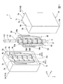
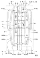
図1は、本発明の第1の実施形態の射出成形金型の一例を示す模式的な斜視図である。図2は、本発明の第1の実施形態の射出成形金型で製造された成形品の模式的な部分断面図である。図3は、本発明の第1の実施形態の射出成形金型の模式的な正面図である。図4は、図2におけるA−A断面図である。
[First Embodiment]
The injection molding die according to the first embodiment of the present invention will be described.
FIG. 1 is a schematic perspective view showing an example of an injection molding die according to the first embodiment of the present invention. FIG. 2 is a schematic partial cross-sectional view of a molded product manufactured by the injection molding die according to the first embodiment of the present invention. FIG. 3 is a schematic front view of the injection molding die according to the first embodiment of the present invention. FIG. 4 is a sectional view taken along line AA in FIG.
本実施形態の射出成形金型で製造する成形品の形状は特に限定されない。成形品の形状は、例えば、箱状、筒状、棒状、板状、枠状、網状などであってもよい。
本実施形態の射出成形金型の型構成は、射出成形金型で製造する成形品の形状に応じて適宜選択できる。例えば、射出成形金型の型構成は、スライドコアを有していてもよいし、有していなくてもよい。
以下では、図1に示す成形品54(図2参照)を製造する射出成形金型1の場合の例で説明する。
The shape of the molded product manufactured by the injection molding die of the present embodiment is not particularly limited. The shape of the molded product may be, for example, a box shape, a cylinder shape, a rod shape, a plate shape, a frame shape, a net shape, or the like.
The mold configuration of the injection molding die of the present embodiment can be appropriately selected according to the shape of the molded product manufactured by the injection molding die. For example, the mold configuration of the injection mold may or may not have the slide core.
Hereinafter, an example in the case of the
図1に示すように、本実施形態の射出成形金型1は、第1スライドコア1A、第2スライドコア1B、および中子1Cを備える。特に図示しないが、射出成形金型1は、例えば、固定側型板、キャビティ型、可動側型板等の周知の部材をさらに備える。
射出成形金型1は、射出成形によって成形品54を製造する目的で用いられる。
例えば、成形品54は、筒状部(tubular portion)と、筒状部から突出する複数の肉厚部と、を有する適宜の形状が可能である。
筒状部の肉厚は、筒状部の軸方向おいて一定である。筒状部の断面形状は、特に限定されない。例えば、筒状部の断面形状は、円形、楕円形、多角形、半月形などであってもよい。
複数の肉厚部は、互いに同形状でもよいし、同形状でなくてもよい。各肉厚部の具体的な形状としては、特に限定されない。例えば、肉厚部の形状は、台状、帯状、ドット状、棒状、ドーム状などであってもよい。例えば、肉厚部の形状は、フランジ状、フィン状、スクリュー状などの板状であってもよい。
複数の肉厚部は、筒状部の軸方向および周方向の少なくとも一方において互いに離間して配置される。
成形品54には、上述の肉厚部に該当しない突起が形成されていてもよい。
以下では、一例として、成形品54が、図1、2に示す形状を有する場合の例で説明する。
As shown in FIG. 1, the injection molding die 1 of this embodiment includes a
The
For example, the molded
The wall thickness of the tubular portion is constant in the axial direction of the tubular portion. The cross-sectional shape of the tubular portion is not particularly limited. For example, the cross-sectional shape of the tubular portion may be a circle, an ellipse, a polygon, a half moon, or the like.
The plurality of thick portions may have the same shape or may not have the same shape. The specific shape of each thick portion is not particularly limited. For example, the shape of the thick portion may be trapezoidal, strip-shaped, dot-shaped, rod-shaped, dome-shaped, or the like. For example, the shape of the thick portion may be a plate shape such as a flange shape, a fin shape, or a screw shape.
The plurality of thick portions are arranged apart from each other in at least one of the axial direction and the circumferential direction of the tubular portion.
The molded
Hereinafter, as an example, a case where the molded
図2に示す例では、成形品54は、筒状部54a、突起部54b、およびフランジ部54cを有する。
筒状部54aは中心軸線Oに沿って延びる円筒である。筒状部54aの内径はD、肉厚はt、長さはLである。
例えば、Lは50mm以上であってもよい。Dは、5mm以上50mm以下であってもよい。tは、0.1mm以上2mm以下であってもよい。
In the example shown in FIG. 2, the molded
The
For example, L may be 50 mm or more. D may be 5 mm or more and 50 mm or less. t may be 0.1 mm or more and 2 mm or less.
突起部54bは、筒状部54aの外周面54dから外周面54dの全周にわたって径方向に突出している。中心軸線Oを含む断面における突起部54bの形状は、w1×h1の矩形である。ここで、w1は、軸方向の幅、h1は、外周面54dからの突出高さを表す。突出方向における突起部54bの先端面は、中心軸線Oと同軸の円筒面である。突起部54bの先端面の外径は、(D+t+h1)である。突起部54bが形成された軸方向の範囲では、成形品54の肉厚は、t+h1になっている。
w1およびh1の大きさは特に限定されない。例えば、図2に示す例では、t<h1<w1である。
The protruding
The sizes of w1 and h1 are not particularly limited. For example, in the example shown in FIG. 2, t<h1<w1.
フランジ部54cは、中心軸線Oを含む断面の大きさが異なる以外は、突起部54bと同様の形状を有する。
中心軸線Oを含む断面におけるフランジ部54cの形状は、w2×h2の矩形である。図2に示す例では、t<w2<w1、h1<h2である。ここで、w2は、軸方向の幅、h2は、外周面54dからの突出高さを表す。突出方向におけるフランジ部54cの先端面は、中心軸線Oと同軸の円筒面である。フランジ部54cの先端面の外径は、D+t+h2である。
The
The shape of the
このように、図2に示す例では、突起部54bは、外周面54d上で周方向に延びる帯状の突起である。これに対して、フランジ部54cは、中心軸線Oに直交する平面に沿って外周面54dから径方向外側に円環状に突出する板状の突起である。
突起部54bは、突起部54b自体が肉厚部であるとも言える。しかし、突出形状のアスペクト比が低いので、h1、w1の具体的な大きさによっては、突起部54bは筒形状が偏肉した肉厚部であるとも言える。
これに対して、フランジ部54cは、突出形状のアスペクト比が高いので、フランジ部54c自体が筒状部54aよりも板状の肉厚部である。
As described above, in the example shown in FIG. 2, the
It can be said that the
On the other hand, since the
突起部54bおよびフランジ部54cの個数および配置間隔は、特に限定されない。
図2に示す例では、突起部54bは3個、フランジ部54cは2個形成されている。突起部54bおよびフランジ部54cは、筒状部54aの軸方向において、交替に配置されている。突起部54bとフランジ部54cとの配置間隔は一定値LTである。
The number and the arrangement interval of the
In the example shown in FIG. 2, three
上述した突起部54bおよびフランジ部54cは、成形品54の軸方向が抜き方向になる型構成の場合、アンダーカット形状である。
肉厚部は、内周面54eに突出されてもよい。ただし、図2に示す例では、内周面54eには突起は形成されていない。
The
The thick portion may project from the inner peripheral surface 54e. However, in the example shown in FIG. 2, no protrusion is formed on the inner peripheral surface 54e.
成形品54の材料は、射出成形可能な樹脂材料であれば特に限定されない。成形品54の材料は、硬質の樹脂材料でもよいし、例えば、エラストマーなどの軟質の樹脂材料でもよい。
The material of the molded
次に、本実施形態の射出成形金型1について説明する。
以下では、図1に示すXYZ直交座標系を参照して説明する場合がある。Z軸は、可動側型板等の移動方向に延びる軸線である。X軸はZ軸に直交する軸線である。Y軸は、X軸を含みZ軸に直交する平面において、X軸と直交する軸線である。X軸、Y軸、およびZ軸にそれぞれ沿う方向を、X方向、Y方向、およびZ方向と称する。
Next, the
In the following, description may be made with reference to the XYZ orthogonal coordinate system shown in FIG. The Z axis is an axis extending in the moving direction of the movable mold plate or the like. The X axis is an axis line orthogonal to the Z axis. The Y axis is an axis line that is orthogonal to the X axis in a plane that includes the X axis and is orthogonal to the Z axis. The directions along the X axis, the Y axis, and the Z axis are referred to as the X direction, the Y direction, and the Z direction, respectively.
第1スライドコア1Aおよび第2スライドコア1Bは、Y方向に対向して配置されている。第1スライドコア1Aおよび第2スライドコア1Bは、射出成形金型1の開閉時に少なくともY方向にスライド移動可能である。
中子1Cは、Z軸に平行な軸線に沿って配置される。中子1Cは、可動側型板に固定されており、可動側型板とともにZ方向に移動可能である。
The
The
第1スライドコア1Aおよび第2スライドコア1Bは、成形品54の外周部の形状を形成する。
第1スライドコア1Aおよび第2スライドコア1Bの形状は、ZX平面に平行な平面に関して面対称である。以下では、第1スライドコア1Aの形状を中心に説明する。
The
The shapes of the
第1スライドコア1Aの外形は、Z方向に細長い略直方体である。第1スライドコア1AのZ方向の端部には、XY平面に平行な第1端面1aが形成されている。第1端面1aは、型を閉じた時には射出成形金型1における固定側型板(不図示)に対向している。
Z方向において第1端面1aと反対側の端部には、XY平面に平行な第2端面1bが形成されている。第2端面1bは、型を閉じたときには射出成形金型1における可動側型板(不図示)に当接している。
第1スライドコア1Aには第2スライドコア1Bと対向する表面にパーティング面1cが形成されている。パーティング面1cは、XZ平面に平行な平面である。
The outer shape of the
A
A
各パーティング面1cには、射出成形金型1が閉じられたときに、成形品54の外形を形成する凹部がそれぞれ形成されている。この凹部と中子1Cとの間には、成形品54の成形をする成形空間が形成される。成形空間の一部を構成する凹部(成形面)は、その表面形状を成形空間に充填された射出樹脂に転写することによって、成形品54の外形を形成する。
各パーティング面1cには、成形空間に成形用樹脂を充填する樹脂流路を形成する凹部がそれぞれ形成されている。
成形空間を形成する凹部は、円筒部成形面4a(成形面)、突起部成形面4b(成形面)、およびフランジ部成形面4c(成形面)からなる。
樹脂流路を形成する凹部は、第1樹脂流路部P1および第2樹脂流路部P2からなる。
Each
Each
The concave portion forming the molding space includes a cylindrical
The concave portion forming the resin flow passage is composed of a first resin flow passage portion P1 and a second resin flow passage portion P2.
円筒部成形面4aは、筒状部54aの外周面54dの半周部の形状を形成する。円筒部成形面4aは、中心軸線OAを中心としてZ方向に延びる半円溝である。本明細書では、半円溝は、延在方向に直交する断面形状が半円の溝と定義される。半円溝において断面における半円の半径は溝半径と称される。
中心軸線OAは、パーティング面1cの中心部においてZ軸に平行に延びている。
円筒部成形面4aの溝半径は、D/2である。円筒部成形面4aは、第1端面1aと第2端面1bとの間をZ方向に貫通している。円筒部成形面4aの長さは、成形品54の全長Lに等しい。
The cylindrical
The central axis OA extends parallel to the Z axis at the center of the
The groove radius of the cylindrical
図3に示すように、突起部成形面4bおよびフランジ部成形面4cは、パーティング面1cおよび円筒部成形面4a上に形成された凹部である。
As shown in FIG. 3, the
突起部成形面4bは、成形品54における突起部54bを形成する。突起部成形面4bは、突起部54bの個数、配置に対応して、3箇所に形成されている。突起部成形面4bの形状は、突起部54bの外形に対応している。具体的には、突起部成形面4bの形状は、Z方向における幅がw1、突起部成形面4bからの深さがh1の角溝である。
突起部成形面4bは、XY平面に平行な平面内で半円状に延びている。突起部成形面4bの溝底面は、中心軸線OAからの半径が(D+t+h1)の円筒面である。
The protruding
The
フランジ部成形面4cは、成形品54におけるフランジ部54cを形成する。フランジ部成形面4cは、フランジ部54cの個数、配置に対応して、2箇所に形成されている。フランジ部成形面4cの形状は、フランジ部54cの外形に対応している。具体的には、フランジ部成形面4cの形状は、Z方向における幅がw2、突起部成形面4bからの深さh2の角溝である。
フランジ部成形面4cは、XY平面に平行な平面内で半円状に延びている。フランジ部成形面4cの溝底面は、中心軸線OAからの半径が(D+t+h2)の円筒面である。
The flange
The flange
図1に示すように、中子1Cは、円筒状の外周面1dを有する円柱部材である。中子1Cは、成形品54の内周面54eの形状を形成する。
中子1Cにおける外周面1dの外径は、内周面54eの外径に対応してDである。中子1Cの長さは、筒状部54aの長さに対応してLである。
中子1Cの軸方向の両端部に形成された端面1e、1fは、外周面1dの中心軸線OCに直交する平面である。
As shown in FIG. 1, the
The outer diameter of the outer
The end faces 1e, 1f formed at both ends in the axial direction of the
図3に示すように、第2スライドコア1Bのパーティング面1cにも、中心軸線OBを中心として、第1スライドコア1Aと同様円円筒部成形面4a、突起部成形面4b、およびフランジ部成形面4cが形成されている。ただし、図3における座標系は、第1スライドコア1Aの姿勢を示している。
射出成形金型1が閉じられた時に第1スライドコア1Aおよび第2スライドコア1Bの各パーティング面1cが当接すると、中心軸線OA、OBは同軸に配置される。このとき、互いにY方向に対向する各円筒部成形面4a、各突起部成形面4b、および各フランジ部成形面4cは、成形品54の外周面の形状を形成する。
二点鎖線で示すように、各円筒部成形面4aで囲まれた内部空間の中心には、中子1CがZ方向に挿入される。中子1Cの端面1e、1fは、それぞれ第1スライドコア1Aおよび第2スライドコア1Bの第1端面1a、第2端面1bと同一平面状にそれぞれ整列する。
これにより、中子1Cの外周面1dと、各円筒部成形面4a、各突起部成形面4b、および各フランジ部成形面4cと、で囲まれた成形空間Sが形成される。
As shown in FIG. 3, also on the
When the parting surfaces 1c of the
As shown by the chain double-dashed line, the
As a result, a molding space S surrounded by the outer
第1樹脂流路部P1および第2樹脂流路部P2は、中心軸線OAを通り、YZ平面に平行な平面を対称面として面対称な形状を有する。以下では、第1樹脂流路部P1の形状を中心に説明する。 The first resin flow path portion P1 and the second resin flow path portion P2 have plane-symmetric shapes with respect to a plane that passes through the central axis OA and that is parallel to the YZ plane. Below, it demonstrates centering around the shape of the 1st resin flow path part P1.
第1樹脂流路部P1は、入口ランナー溝2A、第1ランナー溝2B、第2ランナー溝2C、第3ランナー溝2D、およびゲート溝3A、3Bを備える。
The first resin flow path portion P1 includes an
入口ランナー溝2Aは、注入口2aと、開口2bとの間に延びる半円溝である。入口ランナー溝2Aの溝半径は一定である。
注入口2aは、入口ランナー溝2Aに射出樹脂Mを注入する目的で設けられた半円の開口部である。注入口2aは、第1端面1aに開口している。
開口2bは、3つの突起部成形面4bのうち中央の突起部成形面4bとX方向において対向する位置に形成されている。開口2bの中心は、突起部成形面4bの幅方向(Z方向)の中心と一致している。以下では、開口2bの中心を通るXY平面に平行な平面を基準面mと称する。本実施形態では、基準面mから各フランジ部成形面4cの幅方向の中心までの距離はいずれもLTである。基準面mから、基準面mが通らない各突起部成形面4bの幅方向の中心までの距離はいずれも2×LTである。
The
The
The
入口ランナー溝2Aの経路は、特に限定されない。図3に示す例では、入口ランナー溝2Aは、注入口2aからZ方向に延び、中心軸線OAから遠ざかるようにX方向に屈曲し、基準面mに向かってZ方向に屈曲し、開口2bと対向する位置で開口2bに向かってX方向に屈曲する経路に沿って形成されている。
入口ランナー溝2Aの内径は、溶融した射出樹脂Mが良好に流れる適宜の大きさとされる。
The path of the
The inner diameter of the
第1ランナー溝2Bは、中心軸線OAに向かって凹状に湾曲した経路に沿う半円溝である。第1ランナー溝2Bの延在方向の両端部は、後述するゲート溝3Aのうち、基準面mの両側で基準面mからそれぞれ最も離れたゲート溝3Aと、それぞれX方向に対向する位置まで延ばされている。第1ランナー溝2Bは、基準面mに関して面対称である。
第1ランナー溝2Bの湾曲形状は、後述する第2ランナー溝2CにおけるX方向の長さをZ方向に変化させる目的で設定される。
図4に示すように、第1ランナー溝2Bの溝半径は一定値rBである。
The
The curved shape of the
As shown in FIG. 4, the groove radius of the
図4に示すように、第2ランナー溝2Cは、第1ランナー溝2Bにおいて後述する第3ランナー溝2Dに面する側面に連通する凹部である。第2ランナー溝2Cにおけるパーティング面1cからの深さはtC(ただし、tC<rB)である。
図3に示すように、第2ランナー溝2Cは、第1ランナー溝2Bの延在方向の略全長にわたって、第1ランナー溝2Bと連通している。第2ランナー溝2CのX方向における幅は、第1ランナー溝2Bの湾曲量に応じてZ方向に変化している。さらに、Y方向において見た第2ランナー溝2Cの形状は、基準面mに関して面対称である。
As shown in FIG. 4, the
As shown in FIG. 3, the
第3ランナー溝2Dは、X方向に直線状に延ばされた半円溝からなる。第3ランナー溝2Dは、第2ランナー溝2Cを間に挟んで第1ランナー溝2Bの全体と、X方向に互いに対向する位置に形成されている。第2ランナー溝2Cは、第3ランナー溝2Dと連通している。
第3ランナー溝2Dの長さは、Z方向における第1ランナー溝2Bの形成範囲の長さと同様である。第3ランナー溝2DのZ方向における中心は、基準面m上に位置する。
図4に示すように、第3ランナー溝2Dの溝半径は一定値rD(ただし、rD>tC)である。
The
The length of the
As shown in FIG. 4, the groove radius of the
ゲート溝3Aは、各突起部成形面4bと、各突起部成形面4bとX方向に対面する第3ランナー溝2Dとを互いに連通させる凹部である。ゲート溝3AはX方向に延びる軸線を中心とする半円溝である。例えば、ゲート溝3Aは、ピンゲートの形状を中心から半分に分割した形状を有する。図4に示すように、ゲート溝3Aの先端部には、突起部成形面4bに開口するゲート開口部3aと、成形空間Sに入る射出樹脂Mの速度を適正化する適宜のランド3bが形成されている。
ゲート溝3Aにおいて、第3ランナー溝2Dに連通する開口部3cの半径は、rD未満である。
ゲート溝3Aは、第3ランナー溝2DをZ方向に流れる射出樹脂Mを突起部成形面4bに向かって分流させる。
The
In the
The
ゲート溝3Bは、各フランジ部成形面4cと、第3ランナー溝2Dとを互いに連通させる以外は、ゲート溝3Aと同様の凹部である。ただし、ゲート溝3Bの長さは、第3ランナー溝2Dから、第3ランナー溝2DとX方向に対向するフランジ部成形面4cまでの距離に応じて、ゲート溝3Aと異なる。
ゲート溝3Bは、第3ランナー溝2DをZ方向に流れる射出樹脂Mをフランジ部成形面4cに向かって分流させる。
The
The
図3に示すように、第2スライドコア1Bのパーティング面1cにも、第1スライドコア1Aにおけると同様の第1樹脂流路部P1および第2樹脂流路部P2が形成されている。
射出成形金型1が閉じられた時に第1スライドコア1Aおよび第2スライドコア1Bの各パーティング面1cが当接すると、互いにY方向に対向する各第1樹脂流路部P1および各第2樹脂流路部P2は、それぞれ流路断面が円形または矩形の樹脂流路F1、F2を形成する。
樹脂流路F1、F2は、それぞれ、入口ランナーR2A(上流ランナー)、第1ランナーR2B(下流ランナー、第1円管状流路、第1ランナー部)、第2ランナーR2C(下流ランナー、第2ランナー部、板状流路)、第3ランナーR2D(下流ランナー、第2円管状流路、第3ランナー部)、およびゲートGA、GBを備える。
As shown in FIG. 3, the first resin flow path portion P1 and the second resin flow path portion P2 similar to those in the
When the parting surfaces 1c of the
The resin flow paths F1 and F2 are respectively an inlet runner R 2A (upstream runner), a first runner R 2B (downstream runner, a first circular tubular flow path, a first runner portion), a second runner R 2C (downstream runner, The second runner part, the plate-like flow path), the third runner R 2D (downstream runner, the second circular tubular flow path, the third runner part), and the gate GA, GB.
入口ランナーR2Aは、Y方向に互いに対向する入口ランナー溝2A同士の組合せによって形成された流路である。入口ランナーR2Aは、射出樹脂Mが注入される注入口2aを有する上流ランナーを構成する。
第1ランナーR2B、第2ランナーR2C、および第3ランナーR2Dは、入口ランナーR2Aおよび各ゲートGA、GBにそれぞれ連通し、注入口2aに注入された射出樹脂Mを各ゲートGA、GBのそれぞれに分流する下流ランナーを構成する。
The inlet runner R 2A is a flow path formed by a combination of the
The first runner R 2B , the second runner R 2C , and the third runner R 2D communicate with the inlet runner R 2A and the gates GA and GB, respectively, and the injection resin M injected into the
第1ランナーR2Bは、Y方向に互いに対向する第1ランナーR2B同士の組合せによって形成された流路である。第1ランナーR2Bは、2×rBの第1内径を有する第1円管状流路である。第1ランナーR2Bの延在方向の中心部(中間部)には、各開口2bが開口している。第1ランナーR2Bは、第2ランナーR2Cおよび第3ランナーR2Dを間に挟んで各ゲートGA、GBに面し、各ゲートGA、GBの並びに沿って延びている。
The first runner R 2B is a flow path formed by a combination of the first runners R 2B facing each other in the Y direction. The first runner R 2B is a first circular tubular flow path having a first inner diameter of 2×rB. Each
第2ランナーR2Cは、Y方向に互いに対向する第2ランナーR2C同士の組合せによって形成された流路である。第2ランナーR2Cは、厚さ方向において2×tCの流路幅を有する板状流路である。
第2ランナーR2Cによって、第1ランナーR2BのX方向の側面には、第1ランナーR2Bの延在方向の略全体にわたって、流路幅と同様の幅2×tCのスリットSL1(図4参照)が形成されている。
流路幅は、第1内径よりも狭いので、第2ランナーR2Cの流路断面は、第1ランナーR2Bの流路断面よりも高抵抗である。
The second runner R 2C is a flow path formed by a combination of the second runners R 2C facing each other in the Y direction. The second runner R 2C is a plate-like flow passage having a flow passage width of 2×tC in the thickness direction.
Due to the second runner R 2C , on the side surface of the first runner R 2B in the X direction, a slit SL1 having a width of 2×tC (FIG. 4) similar to the flow path width is formed over substantially the entire extending direction of the first runner R 2B . (See) is formed.
Since the channel width is narrower than the first inner diameter, the channel cross section of the second runner R 2C has a higher resistance than the channel cross section of the first runner R 2B .
図3に示すように、各ゲートGA、GBに対する対面方向(X方向)における第2ランナーR2Cの長さは、第1ランナーR2Bの延在方向において基準面mから離れるにつれて短くなっている、例えば、Z方向における中央のゲートGA(第1ゲートと称する)に対面する部位の第2ランナーR2Cの長さは、L0である。中央のゲートGAの隣に配置された各ゲートGBに対面する部位の第2ランナーR2Cの長さは、L1(ただし、L1<L0)である。各ゲートGAよりも基準面mから離れて配置された各ゲートGA(第2ゲートと称する)に対面する部位の第2ランナーR2Cの長さは、L2(ただし、L2<L1)である。
長さL0、L1、L2は、開口2bから第1ゲート、ゲートGB、第2ゲートまでの射出樹脂Mの到達時間が均等になる長さに設定される。各長さは、例えば、射出樹脂Mの流動シミュレーションなどによって決めることができる。
As shown in FIG. 3, the length of the second runner R 2C in the facing direction (X direction) with respect to each of the gates GA and GB becomes shorter as the distance from the reference plane m increases in the extending direction of the first runner R 2B . For example, the length of the second runner R 2C at the portion facing the central gate GA (referred to as the first gate) in the Z direction is L0. The length of the second runner R 2C at the portion facing each gate GB arranged next to the central gate GA is L1 (where L1<L0). The length of the second runner R 2C at a portion facing each gate GA (referred to as a second gate) arranged farther from the reference plane m than each gate GA is L2 (where L2<L1).
The lengths L0, L1, and L2 are set to lengths such that the arrival time of the injection resin M from the
第3ランナーR2Dは、Y方向にそれぞれ互いに対向する第3ランナーR2D同士の組合せによって形成された流路である。第3ランナーR2Dは、2×rDの第2内径を有する第2円管状流路である。第2内径は、第2ランナーR2Cの流路幅よりも大きいので、第3ランナーR2Dの流路断面は、第2ランナーR2Cの流路断面よりも低抵抗である。
第2ランナーR2Cによって、第3ランナーR2DのX方向の側面には、第3ランナーR2Dの延在方向(Z方向)の略全体にわたって、流路幅と同様の幅2×tCのスリットSL2(図4参照)が形成されている。
The third runner R 2D is a flow path formed by a combination of the third runners R 2D that face each other in the Y direction. The third runner R 2D is a second circular tubular flow path having a second inner diameter of 2×rD. Since the second inner diameter is larger than the flow passage width of the second runner R 2C , the flow passage cross section of the third runner R 2D has a lower resistance than the flow passage cross section of the second runner R 2C .
Due to the second runner R 2C , on the side surface of the third runner R 2D in the X direction, a slit having a width of 2×tC, which is similar to the flow path width, is formed over substantially the entire extending direction (Z direction) of the third runner R 2D. SL2 (see FIG. 4) is formed.
ゲートGAは、Y方向に互いに対向するゲート溝3A同士の組合せによって形成された流路である。ゲートGBは、Y方向に互いに対向するゲート溝3B同士の組合せによって形成された流路である。
The gate GA is a flow path formed by a combination of the
このような構成により、第2ランナーR2Cにおいて、第1ランナーR2Bから各ゲートGA、GBに向かう流路の最短距離は、開口2bと各ゲートGA、GBまでのそれぞれの最短距離によって異なっている。例えば、第2ランナーR2Cにおいては、第1ランナーR2Bから、開口2bからの距離が最も近い第1ゲートに向かう流路における最短距離がL0である。これに対して、開口2bからの最短距離が順次長くなる第1ランナーR2B、第2ゲートに向かう第2ランナーR2Cの流路においては、第1ランナーR2Bから各ゲートに向かう最短距離が、それぞれL1、L2のように、開口2bから各ゲートまでの最短距離が長いほど短くなっている。
With such a configuration, in the second runner R 2C , the shortest distance of the flow path from the first runner R 2B to each gate GA, GB differs depending on the shortest distance between the
射出成形金型1を用いた成形品54の製造工程について説明する。
図5は、本発明の第1の実施形態の射出成形金型における射出樹脂の流れの説明図である。
A manufacturing process of the molded
FIG. 5: is explanatory drawing of the flow of the injection resin in the injection mold of the 1st Embodiment of this invention.
成形品54を製造する場合、射出成形金型1が図示略の射出成形機に取り付けられる。射出成形金型1が閉じられた状態では、第1スライドコア1A、第2スライドコア1B、および中子1Cを含む組立体の内部に、成形空間Sと、成形空間Sに突起部成形面4b、フランジ部成形面4cを通して連通する樹脂流路F1、F2と、が形成される。
樹脂流路F1、F2の第1端面1aにおける各注入口2aは、キャビティ型板(図示略)内のスプルー(図示略)に連通している。
射出成形機から溶融状態で射出される射出樹脂Mは、スプルーおよび各注入口2aを通して、樹脂流路F1、F2に注入される。射出樹脂Mの注入量は、成形空間Sおよび樹脂流路F1、F2の合計容積に応じて予め決められている。
When manufacturing the molded
Each
The injection resin M injected in a molten state from the injection molding machine is injected into the resin flow paths F1 and F2 through the sprue and the
樹脂流路F1、F2は配置位置が異なる以外は同様の流路なので、以下では、樹脂流路F1の例で説明する。
図5に示すように、樹脂流路F1の注入口2aから注入された射出樹脂Mは、入口ランナーR2A内でその経路に沿って、開口2bに向かって流れる。開口2bの近傍では、射出樹脂Mは、入口ランナーR2Aの末端部の延びるX方向に流れる。
射出樹脂Mは、開口2bから第1ランナーR2Bに入ると、第1ランナーR2Bの両端部に向かって流れる(長い矢印参照)。開口2bの近傍では第1ランナーR2BがZ方向に延びているので、開口2bの近傍には、X方向からZ方向の2方向に分岐するT字状の分岐流路が形成されている。このため、射出樹脂Mの流れは、第1端面1aに向かう第1ランナーR2Bと、第2端面1bに向かう第1ランナーR2Bとの両方に二等分される。
第1ランナーR2Bの側面には、スリットSL1が開口しているので、射出樹脂Mの一部の樹脂MCは、スリットSL1を通して、第2ランナーR2Cに流入する。
しかし、スリットSL1の開口幅(Y方向の幅)は、第1ランナーR2Bの第1内径に比べて小さいので、第2ランナーR2Cの流路抵抗は、第1ランナーR2Bの流路抵抗に比べて大きい。この結果、射出樹脂Mのうち樹脂MCを除く樹脂MBは、第1ランナーR2Bの延在方向に流れる。樹脂MBの量は、樹脂MCに比べて格段に多い。
The resin flow paths F1 and F2 are similar to each other except that the arrangement positions are different. Therefore, the resin flow path F1 will be described below as an example.
As shown in FIG. 5, the injection resin M injected from the
When the injection resin M enters the first runner R 2B through the
The side surface of the first runner R 2B, since the slits SL1 is opened, part of the resin MC of injected resin M, through the slit SL1, flows into the second runner R 2C.
However, the opening width (Y direction width) of the slit SL1 is smaller than the first inner diameter of the first runner R 2B, the flow path resistance of the second runner R 2C is a flow path resistance of the first runner R 2B Big compared to. As a result, the resin MB other than the resin MC in the injection resin M flows in the extending direction of the first runner R 2B . The amount of resin MB is much larger than that of resin MC.
流れ方向における流路断面の大きさの違いに応じて、樹脂MCの流速は、樹脂MBの流速よりも低い。このため、樹脂MCが第3ランナーR2Dを通過して各ゲートGA、GBに流入する前に、樹脂MCが第1ランナーR2B内に充填される。第1ランナーR2Bに射出樹脂Mが充填される充填完了時(以下、第1充填完了時と称する)以後は、第1ランナーR2B内の射出樹脂Mの全体に略均等な射出圧がかかるので、スリットSL1から第2ランナーR2C内に全体的に射出樹脂Mが押し出される。 The flow velocity of the resin MC is lower than the flow velocity of the resin MB due to the difference in the size of the flow passage cross section in the flow direction. Therefore, the resin MC is filled in the first runner R 2B before the resin MC passes through the third runner R 2D and flows into the gates GA and GB. After the completion of filling the first runner R 2B with the injection resin M (hereinafter referred to as the first filling completion), a substantially uniform injection pressure is applied to the entire injection resin M in the first runner R 2B . Therefore, the injection resin M is entirely extruded into the second runner R 2C from the slit SL1.
第1充填完了時までの間、第2ランナーR2Cには、徐々に樹脂MCが流入する。樹脂MBが第1ランナーR2Bに充填されるには、第1ランナーR2Bの長さに応じた時間を要するので、第2ランナーR2Cに流入する樹脂MCのタイミングは、基準面mからZ方向に離れるほど遅くなる。樹脂MCにかかる圧力は、基準面mからZ方向に離れるほど低い。これにより、第2ランナーR2Cに流入する樹脂MCの量は、基準面mからZ方向に離れるほど少なくなる。同様に、樹脂MCの流速も基準面mからZ方向に離れるほど小さくなる。
このため、第1ランナーR2Bが直線状の場合には、第2ランナーR2C内を進む樹脂MCは、基準面m上の流動長が最も長い扇形状に広がる。しかし、本実施形態では、第1ランナーR2Bが第3ランナーR2Dに向かって凹状に湾曲しているので、湾曲量に応じて樹脂MCの先端面が平坦化される。このため、第2ランナーR2Cの流路断面の抵抗の大きさと、第1ランナーR2Bの湾曲量と、を適宜設定することによって、第2ランナーR2CのZ方向における充填時間の差を低減することができる。
なお、本実施形態のように、第2ランナーR2Cの出口が第3ランナーR2Dに沿う直線状の場合第1ランナーR2Bの湾曲量は、第1ランナーR2Bの延在方向における第2ランナーR2Cの流路長さの分布を規定している。
The resin MC gradually flows into the second runner R 2C until the completion of the first filling. The resin MB is charged into the first runner R 2B is, since it takes a time corresponding to the length of the first runner R 2B, timings of the resin MC that flows into the second runner R 2C is Z from the reference plane m The farther you go, the slower it gets. The pressure applied to the resin MC is lower as it goes away from the reference plane m in the Z direction. As a result, the amount of the resin MC flowing into the second runner R 2C becomes smaller as it goes away from the reference plane m in the Z direction. Similarly, the flow velocity of the resin MC decreases as the distance from the reference surface m increases in the Z direction.
Therefore, when the first runner R 2B has a linear shape, the resin MC that travels in the second runner R 2C spreads in a fan shape having the longest flow length on the reference surface m. However, in the present embodiment, since the first runner R 2B is curved concavely toward the third runner R 2D , the tip end surface of the resin MC is flattened according to the amount of bending. Therefore, by appropriately setting the magnitude of the resistance of the flow passage cross section of the second runner R 2C and the bending amount of the first runner R 2B , the difference in the filling time in the Z direction of the second runner R 2C can be reduced. can do.
Incidentally, as in this embodiment, amount of curvature of the outlet third case straight along the runner R 2D first runner R 2B in the second runner R 2C is first in the extending direction of the first runner R 2B 2 It defines the distribution of the flow path length of the runner R 2C .
このようにして、樹脂MCの先端は、第3ランナーR2Dに向かって進むにつれて、X方向において平坦化される。この結果、Z方向の各位置において、略同時に第2ランナーR2Cが充填される。第2ランナーR2Cの充填完了時を以下では、第2充填完了時と称する。 In this way, the tip of the resin MC is flattened in the X direction as it advances toward the third runner R 2D . As a result, at each position in the Z direction, the second runner R 2C is filled almost simultaneously. Hereinafter, the time when the filling of the second runner R 2C is completed is referred to as the time when the second filling is completed.
第2ランナーR2Cに流入する樹脂MCは、第1充填完了時以前では乱流である。射出成形金型1をより小型化する目的で、第2ランナーR2CにおけるX方向の長さを短くすると、樹脂MCの先端面のX方向の位置がZ方向においてある程度ばらつくことも考えられる。
本実施形態では、下流ランナーに第3ランナーR2Dを備えることで、樹脂MCの先端面の乱れによる、射出樹脂Mの各ゲートGA、GBへの到達タイミングのずれを低減している。
第2ランナーR2CをX方向に横断した樹脂MCは、スリットSL2を通して、第3ランナーR2D内に流入する。第3ランナーR2Dの第2内径は、スリットSL2の開口幅(Y方向の幅)よりも大きい。第3ランナーR2Dに入る樹脂MDは、第3ランナーR2D内に噴出すると、第3ランナーR2D内に分散し、かつ流速が低下する。
これにより、樹脂MDは、第3ランナーR2D内にある程度充填された後、近くのゲートから、成形空間Sに流入する。
この結果、樹脂MCの先端面のばらつきによって、第3ランナーR2Dの長手方向における樹脂MDの流入量にばらついいても、樹脂MDが各ゲートに到達する時間は、均等化される。
The resin MC flowing into the second runner R 2C is turbulent before the completion of the first filling. When the length of the second runner R 2C in the X direction is shortened for the purpose of further downsizing the injection molding die 1, it is considered that the position of the tip end surface of the resin MC in the X direction varies to some extent in the Z direction.
In the present embodiment, the downstream runner is provided with the third runner R 2D to reduce the deviation of the arrival timing of the injection resin M to the gates GA and GB due to the disturbance of the front end surface of the resin MC.
The resin MC that has crossed the second runner R 2C in the X direction flows into the third runner R 2D through the slit SL2. The second inner diameter of the third runner R 2D is larger than the opening width (width in the Y direction) of the slit SL2. Resin MD entering the third runner R 2D is, when injected into the third runner R in 2D, dispersed in the third runner R in 2D, and the flow rate is reduced.
As a result, the resin MD is filled into the third runner R 2D to some extent, and then flows into the molding space S from the nearby gate.
As a result, even if the inflow amount of the resin MD in the longitudinal direction of the third runner R 2D varies due to the variation of the tip end surface of the resin MC, the time for the resin MD to reach each gate is equalized.
このように、本実施形態では、各ゲートGA、GBは、Z方向における位置が異なっていても、射出樹脂Mが到達する時間は均等である。
第3ランナーR2D内に射出樹脂Mが充填された後は、下流ランナーにおける射出樹脂Mの全体に略均等な射出圧がかかるので、各ゲートGA、GBを通して、成形空間S内に順次射出樹脂Mが均等に充填される。
As described above, in this embodiment, the gates GA and GB have the same arrival time of the injection resin M even if the positions in the Z direction are different.
After the third runner R 2D is filled with the injection resin M, a substantially uniform injection pressure is applied to the entire injection resin M in the downstream runner, so that the injection resin is sequentially injected into the molding space S through the gates GA and GB. M is filled evenly.
成形空間S内に充填された射出樹脂Mは、第1スライドコア1A、第2スライドコア1B、および中子1Cへの熱伝導が進むことによって、冷却される。射出樹脂Mの温度がガラス転移点以下になる程度の時間放置されると、図1に示すように、射出成形金型1内の射出樹脂Mが固化した成形体50が形成される。この後、射出成形金型1の型開きが実行される。
The injection resin M filled in the molding space S is cooled by heat conduction to the
射出成形金型1が開きだすと、第1スライドコア1Aおよび第2スライドコア1Bは、Y方向に互いに離間する。これにより、成形体50の脱型が可能になる。
成形体50は、成形品54と、流路樹脂部Q1、Q2と、からなる。
流路樹脂部Q1は、樹脂流路F1に充填された射出樹脂Mが固化することによって形成される。流路樹脂部Q1は、ランナー樹脂部52およびゲート樹脂部53A、53Bからなる。ランナー樹脂部52は、上流ランナーおよび下流ランナーの形状が転写された部分である。ゲート樹脂部53A、53Bは、それぞれゲートGA、GBの形状が転写された部分である。
流路樹脂部Q2は、樹脂流路F2に充填された射出樹脂Mが固化することによって形成される。流路樹脂部Q2は、流路樹脂部Q1と同様、ランナー樹脂部52およびゲート樹脂部53A、53Bからなる。
成形体50から流路樹脂部Q1、Q2が切り離されることによって、成形品54が製造される。
When the
The molded
The flow path resin portion Q1 is formed by solidifying the injection resin M filled in the resin flow path F1. The flow path resin portion Q1 includes a
The flow path resin portion Q2 is formed by solidifying the injection resin M filled in the resin flow path F2. The flow channel resin portion Q2 is composed of a
The molded
射出成形金型1によれば、下流ランナーにおいて、流路断面の抵抗の大きさが異なる第1ランナーR2B、第2ランナーR2C、および第3ランナーR2Dを備えることで、射出樹脂Mを各ゲートGA、GBに均等に分流することできる。その際、開口2bから各ゲートGA、GBの到達時間が均等化されるので、各ゲートGA、GBからへの射出樹脂Mの供給量も均等化される。
本実施形態では、第1ランナーR2B、第2ランナーR2C、および第3ランナーR2Dは、一続きの流路からなり、開口2bから、各ゲートGA、GBへの射出樹脂Mの流路長さは均等ではない。例えば、開口2bから第1ゲートまでの流路(以下、中央流路と称する)の代表的な長さは、(2×rB+L0+2×rD)である。これに対して、開口2bから第2ゲートまでの流路(以下、端部流路と称する)の代表的な長さは、(2×LT+L2+2×rD)よりも大きい。このため、端部流路は中央流路に比べて端部流路の方が格段に長い。
しかし、中央流路は、高抵抗であって流速が低速になる第2ランナーR2Cが大部分を占めるのに対して、端部流路は、低抵抗であって流速が高速になる第1ランナーR2Bが大部分を占めており、第2ランナーR2Cを通る長さが短い。この結果、開口2bから各ゲートへの到達時間は、互いに等しくなる。
According to the injection molding die 1, the downstream runner is provided with the first runner R 2B , the second runner R 2C , and the third runner R 2D having different resistances in the cross section of the flow path, so that the injection resin M The gates GA and GB can be evenly distributed. At this time, since the arrival times of the gates GA and GB from the
In the present embodiment, the first runner R 2B , the second runner R 2C , and the third runner R 2D consist of a continuous flow path, and the flow path of the injection resin M from the
However, the central flow path is dominated by the second runner R 2C having high resistance and low flow velocity, whereas the end flow path has low resistance and high flow velocity. The runner R 2B occupies the majority, and the length passing through the second runner R 2C is short. As a result, the arrival times from the
本実施形態の射出成形金型1では、長い端部流路は、成形空間Sの長手方向に配置しているため、下流ランナー全体が成形空間Sの長手方向に細長い矩形状の範囲に形成されている。これにより、X方向における射出成形金型1の大きさがコンパクトになっている。
例えば、射出樹脂Mの注入口から各ゲートまでの間に等長の複数の流路を設ける比較例の場合には、ゲートが1列に並んでいると、各流路を湾曲させるとともに、各流路同士の干渉を避ける必要がある。この結果、ゲートの数が増えるほど、ゲートの並びに直交する方向に広大な流路スペースが必要になる。しかし、本実施形態では、比較例のような流路スペースが不要である。
さらに、比較例の場合、ゲートの間隔が密集すると、さらに流路スペースの確保が困難になるが、本実施形態では、ゲートがより密集しても、同様の下流ランナーを用いることができる。
In the injection molding die 1 of the present embodiment, since the long end passages are arranged in the longitudinal direction of the molding space S, the entire downstream runner is formed in the elongated rectangular range in the longitudinal direction of the molding space S. ing. As a result, the size of the injection molding die 1 in the X direction becomes compact.
For example, in the case of the comparative example in which a plurality of flow passages of equal length are provided between the injection port of the injection resin M and each gate, if the gates are arranged in one row, each flow passage is curved and It is necessary to avoid interference between the flow paths. As a result, as the number of gates increases, a wider flow path space is required in the direction orthogonal to the gates. However, in this embodiment, the flow passage space as in the comparative example is unnecessary.
Further, in the case of the comparative example, if the gates are closely packed, it becomes more difficult to secure the flow path space, but in the present embodiment, even if the gates are more closely packed, the same downstream runner can be used.
本実施形態の射出成形金型1によれば、射出樹脂を複数のゲートに均等に分流することができ、小型化が可能である。
特に、第3ランナーR2Dを備えることで、上述のように、第3ランナーR2Dを有しない場合に比べて、第2ランナーR2CをX方向により短縮することが可能になる。
According to the injection molding die 1 of the present embodiment, the injection resin can be evenly distributed to the plurality of gates, and the size can be reduced.
In particular, by providing the third runner R 2D, as described above, as compared to the case not having a third runner R 2D, it is possible to a second runner R 2C shortened by the X-direction.
射出成形金型1によれば、ゲートGA、GBが、成形品54における肉厚部を構成する突起部54b、フランジ部54cを成形する突起部成形面4b、フランジ部成形面4cにそれぞれに開口している。
これにより、射出樹脂Mは、成形品54における突起部54b、外周面54dなどの肉厚部に対応する成形空間Sから充填される。この場合、射出樹脂Mは、成形空間S内において1肉厚部に対応して流路抵抗が小さい空間から、より肉薄の筒状部に対応して流路抵抗が大きい空間に向かって流れる。この結果、射出樹脂Mの流動方向の先端面における乱流が発生しにくい。
さらに、充填不足が発生しやすい肉厚部に対応する空間に先に射出樹脂Mを充填するので、肉厚部における充填量不足が防止できる。
ゲートGA、GBは、成形空間Sの長手方向に沿って複数設けられているので、成形空間Sの軸方向の端部にゲートを設ける場合に比べて、1つのゲートから充填される射出樹脂Mの流動長がより短くなる。この結果、流動方向の先端部における射出樹脂Mの温度低下がより少なくなるので、射出樹脂Mの粘度が低いうちに射出樹脂Mの充填が完了できる。これにより、成形品54の寸法精度が良好になる。
According to the injection molding die 1, the gates GA and GB are opened in the
As a result, the injection resin M is filled from the molding space S corresponding to the thick portions such as the
Furthermore, since the injection resin M is first filled in the space corresponding to the thick portion where insufficient filling is likely to occur, insufficient filling of the thick portion can be prevented.
Since a plurality of gates GA and GB are provided along the longitudinal direction of the molding space S, compared to the case where a gate is provided at the axial end of the molding space S, the injection resin M filled from one gate is filled. Has a shorter flow length. As a result, the temperature drop of the injection resin M at the tip portion in the flow direction becomes smaller, so that the filling of the injection resin M can be completed while the viscosity of the injection resin M is low. This improves the dimensional accuracy of the molded
[第2の実施形態]
本発明の第2の実施形態の射出成形金型について説明する。
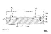
図6は、本発明の第2の実施形態の射出成形金型の主要部の模式的な断面図である。
[Second Embodiment]
An injection molding die according to the second embodiment of the present invention will be described.
FIG. 6 is a schematic cross-sectional view of a main part of an injection molding die according to the second embodiment of the present invention.
図1に示すように、本実施形態の射出成形金型11は、第1の実施形態と同様の成形品54(図2参照)を製造する。
射出成形金型11は、第1の実施形態の射出成形金型1における第1スライドコア1A、第2スライドコア1Bに代えて、第1スライドコア11A、第2スライドコア11Bを備える。第1スライドコア11Aは、第1スライドコア1Aの第1樹脂流路部P1に代えて、第1樹脂流路部P11を備える。第2スライドコア11Bは、第2スライドコア1Bの第2樹脂流路部P2に代えて、第2樹脂流路部P12を備える。
以下、第1の実施形態と異なる点を中心に説明する。
As shown in FIG. 1, the injection mold 11 of this embodiment produces a molded product 54 (see FIG. 2) similar to that of the first embodiment.
The injection molding die 11 includes a
Hereinafter, the points different from the first embodiment will be mainly described.
図3に示すように、第1樹脂流路部P11および第2樹脂流路部P12は、中心軸線OAを通り、YZ平面に平行な平面を対称面として面対称な形状を有する。以下では、第1樹脂流路部P11の形状を中心に説明する。 As shown in FIG. 3, the first resin flow path portion P11 and the second resin flow path portion P12 have plane-symmetric shapes with respect to a plane that passes through the central axis OA and is parallel to the YZ plane. Below, it demonstrates centering around the shape of the 1st resin flow path part P11.
第1樹脂流路部P11は、第1樹脂流路部P1における第2ランナー溝2Cに代えて、第2ランナー溝12Cを備える。
図6に示すように、第2ランナー溝12Cは、入口ランナー溝2Aおよびゲート溝13Cを備える。図6は、図3におけるB−B断面図である。
第2ランナー溝12Cは、第1の実施形態における第2ランナー溝2Cと溝の深さのみが異なる。第2ランナー溝12Cのパーティング面1cからの深さは、基準面mと交差するZ方向の中心ではt1、Z方向の両端部ではそれぞれt2(ただし、t1<t2<rB、t2<rD)である。Z方向の中心から両端部までの深さは、基準面mから離れるにつれて、t1からt2に向かって漸次増大する。
The first resin flow path portion P11 includes a
As shown in FIG. 6, the
The
このような構成により、射出成形金型11が閉じられた時に第1スライドコア11Aおよび第2スライドコア11Bの各パーティング面1cが当接すると、互いにY方向に対向する各第2ランナー溝12Cは、図6に実線および二点鎖線で示すように、両凹レンズの断面のような流路断面を形成する。これにより、第1の実施形態における第2ランナーR2Cに代えて、各第2ランナー溝12Cで囲まれた第2ランナーR12C(下流ランナー)が形成される。
With such a configuration, when the parting surfaces 1c of the
射出成形金型11によれば、第2ランナーR12Cにおける流路断面の抵抗がZ方向において変化している点が、射出成形金型1と異なる。
第2ランナーR12Cでは、基準面mの近傍の流路断面が最小なので、流路抵抗が最大である。第2ランナーR12Cの流路抵抗は、基準面mからZ方向に離れるにつれて低下し、Z方向の両端部で最小になる。
これにより、第2ランナーR12Cにおける第1充填完了時までの樹脂MCの流速が、基準面mから遠ざかるにつれて速くなる。これにより、端部流路における樹脂MCの第2ゲートへの到達時間を短縮することができる。このため、到達時間のバランスをとるために、中央流路を長くする必要がないので、射出成形金型11をX方向に大型化させることなく、射出樹脂Mの到達時間を均等化できる。
The injection mold 11 differs from the
In the second runner R 12C , since the flow passage cross section near the reference plane m is the smallest, the flow passage resistance is the maximum. The flow path resistance of the second runner R 12C decreases with increasing distance from the reference plane m in the Z direction, and becomes minimum at both ends in the Z direction.
As a result, the flow velocity of the resin MC in the second runner R 12C until the completion of the first filling increases as the distance from the reference surface m increases. As a result, the time required for the resin MC to reach the second gate in the end channel can be shortened. For this reason, it is not necessary to lengthen the central flow path in order to balance the arrival times, so that the arrival times of the injection resin M can be equalized without increasing the size of the injection mold 11 in the X direction.
本実施形態の射出成形金型11によれば、第1の実施形態と同様、射出樹脂を複数のゲートに均等に分流することができ、小型化が可能である。
特に、本実施形態では、第1ランナーR2Bの湾曲量をあまり大きくすることができない場合にも、第2ランナーR12CのZ方向の流路断面の抵抗の大きさを変えることで、より大きな湾曲を形成したのと同等の作用が得られる。このため、射出成形金型11は、第1の実施形態の射出成形金型1に比べてさらなる小型化が可能である。
According to the injection molding die 11 of the present embodiment, as in the first embodiment, the injection resin can be evenly distributed to a plurality of gates, and the size can be reduced.
In particular, in the present embodiment, even when the bending amount of the first runner R 2B cannot be made too large, it is possible to obtain a larger value by changing the magnitude of the resistance of the flow passage cross section of the second runner R 12C in the Z direction. An effect equivalent to that of forming a curve is obtained. Therefore, the injection mold 11 can be further downsized as compared with the
[第3の実施形態]
本発明の第3の実施形態の射出成形金型について説明する。
図7は、本発明の第3の実施形態の射出成形金型の主要部を示す模式的な正面図である。
[Third Embodiment]
An injection molding die according to the third embodiment of the present invention will be described.
FIG. 7 is a schematic front view showing a main part of an injection molding die according to the third embodiment of the present invention.
図7に主要部を示す本実施形態の射出成形金型21は、第1の実施形態と同様の成形品54(図2参照)を製造する。
射出成形金型21は、第1の実施形態の射出成形金型1における第1スライドコア1Aに代えて、第1スライドコア21Aを備える。図示は省略するが射出成形金型21は、第1の実施形態における第2スライドコア1Bに代えて、第1スライドコア21Aと同様の構成を有する第2スライドコアを備える。
第1スライドコア21Aは、第1スライドコア1Aの第1樹脂流路部P1に代えて、第1樹脂流路部P21を備える。図示は省略するが、第1スライドコア21Aは、第2樹脂流路部をさらに備える。第2樹脂流路部は、中心軸線OAを通り、YZ平面に平行な平面を対称面として面対称な形状を有する。
以下、第1の実施形態と異なる点を中心に説明する。
The injection-molding die 21 of the present embodiment, the main part of which is shown in FIG. 7, manufactures a molded product 54 (see FIG. 2) similar to that of the first embodiment.
The injection molding die 21 includes a
The
Hereinafter, the points different from the first embodiment will be mainly described.
第1樹脂流路部P21は、第1樹脂流路部P1における第2ランナー溝2Cに代えて、第2ランナー溝22Cを備える。
第2ランナー溝22Cは、第1ランナー溝2Bと、第3ランナー溝2Dとに、連通する複数の半円溝22cからなる。各半円溝22cはX方向に延ばされている。ただし、各半円溝22cの少なくとも一部は、ZX平面において、X方向と斜交する方向に延ばされていてもよい。
各半円溝22cの溝半径は、一定値rC(ただし、rC<rB、rC<rD)である。ただし、各半円溝22cの溝半径は、Z方向において変化されてもよい。例えば、各半円溝22cの溝半径は、基準面mから離れるほど大きくなってもよい。
半円溝22cの個数は、各ゲートGA、GBの個数より多ければ特に限定されない。半円溝22cの個数は、各ゲートGA、GBの2倍以上であることがより好ましい。
半円溝22cのZ方向における配置間隔は、図7に示す例では等間隔である。ただし、半円溝22cのZ方向における単位長さ当たりの配列密度は、Z方向において変化していてもよい。例えば、半円溝22cの配列密度は、基準面mから離れるほど高くなっていてもよい。特に、半円溝22cは、基準面m上には形成されないことがより好ましい。
The first resin flow path portion P21 includes a
The
The groove radius of each
The number of the
In the example shown in FIG. 7, the
このような構成により、射出成形金型21が閉じられた時に第1スライドコア21Aおよび図示略の第2スライドコアの各パーティング面1cが当接すると、第2ランナー溝22Cにおいて、互いにY方向に対向する各半円溝22cは、流路断面が円形の第2ランナーRi(ただし、i=1,2,…,n、nは5以上の整数)(下流ランナー、第2ランナー部)を形成する。
With this configuration, when the parting surfaces 1c of the
第1の実施形態では、第2ランナーR2Cが、Z方向において流路が平板状に連続していたのに対して、各第2ランナーRiは、それぞれ円形断面を有することと、Z方向において互いに連通していない点が異なる。各第2ランナーRiに流れる射出樹脂Mは、第1の実施形態と同様、第3ランナーR2Dに流入した後、各ゲートGA、GBに分流される。
各第2ランナーRiの内径は、2×rC(<2×rD)なので、各第2ランナーRiの流路断面の抵抗は、第1ランナーR2Bの流路断面の抵抗よりも大きい。
各第2ランナーRiの個数、配置ピッチ、rCの大きさを適宜変更することによって、第2ランナーR22C全体として流路抵抗を、第1の実施形態における第2ランナーR2Cと同等にすることが可能である。
これにより、第1の実施形態と同様、射出樹脂Mの開口2bから各ゲートGA、GBへの到達時間が均等化される。
In the first embodiment, the flow path of the second runner R 2C is continuous in the Z direction, whereas each of the second runners Ri has a circular cross section, and in the Z direction, The difference is that they are not in communication with each other. The injection resin M flowing in each second runner Ri flows into the third runner R 2D and then is split into each gate GA and GB, as in the first embodiment.
Since the inner diameter of each second runner Ri is 2×rC (<2×rD), the resistance of the flow passage cross section of each second runner Ri is larger than the resistance of the flow passage cross section of the first runner R 2B .
By appropriately changing the number of second runners Ri, the arrangement pitch, and the size of rC, the flow passage resistance of the second runner R 22C as a whole is made equal to that of the second runner R 2C in the first embodiment. Is possible.
As a result, as in the first embodiment, the arrival times of the injection resin M from the
本実施形態の射出成形金型11によれば、第1の実施形態と同様、射出樹脂を複数のゲートに均等に分流することができ、小型化が可能である。
特に、第2ランナーRiの個数、配置ピッチ、rCの大きさを適宜変更することによって、到達時間を調整できるので、第1スライドコア11Aの製作、修正が容易になる。
以上では、rCが一定の場合の例で説明したが、各第2ランナーRiのrCの大きさは、各第2ランナーRiのZ方向における配置位置によって変更されてもよい。この場合、第2ランナーRiの個数、配置ピッチに加えて、第2ランナーRiのそれぞれのrCの大きさを適宜変更することによって、到達時間の均等化がさらに容易となる。特に、各第2ランナーRiの流路断面の大きさを、第2ランナーR22CのZ方向における中央部から両端部に向かって大きくすれば、上記第2の実施形態と同様にして、第2ランナーR22CのX方向の配置スペースを低減することもできる。
According to the injection molding die 11 of the present embodiment, as in the first embodiment, the injection resin can be evenly distributed to a plurality of gates, and the size can be reduced.
In particular, since the arrival time can be adjusted by appropriately changing the number of second runners Ri, the arrangement pitch, and the size of rC, it is easy to manufacture and modify the
Although the example in which rC is constant has been described above, the size of rC of each second runner Ri may be changed depending on the arrangement position of each second runner Ri in the Z direction. In this case, the arrival times can be more easily equalized by appropriately changing the size of each of the second runners Ri, in addition to the number and arrangement pitch of the second runners Ri. In particular, if the size of the flow passage cross section of each second runner Ri is increased from the central portion of the second runner R 22C in the Z direction toward both end portions, the second runner Ri is provided in the same manner as in the second embodiment. It is also possible to reduce the arrangement space of the runner R 22C in the X direction.
[第4の実施形態]
本発明の第4の実施形態の射出成形金型について説明する。
図8は、本発明の第4の実施形態の射出成形金型の主要部の一例を示す模式的な正面図である。図9は、図8におけるC−C断面図である。
[Fourth Embodiment]
An injection molding die according to the fourth embodiment of the present invention will be described.
FIG. 8 is a schematic front view showing an example of a main part of an injection molding die according to the fourth embodiment of the present invention. FIG. 9 is a sectional view taken along line CC of FIG.
図8、9に主要部を示す本実施形態の射出成形金型31は、第1の実施形態と同様の成形品54(図2参照)を製造する。
射出成形金型31は、第1の実施形態の射出成形金型1における第1スライドコア1Aおよび第2スライドコア1Bに代えて、第1スライドコア31Aおよび第2スライドコア31B(図9参照)を備える。
図8に示すように、第1スライドコア31Aは、第1スライドコア1Aの第1樹脂流路部P1に代えて、第1樹脂流路部P31を備える。図示は省略するが、第1スライドコア31Aは、第2樹脂流路部をさらに備える。第2樹脂流路部は、中心軸線OAを通り、YZ平面に平行な平面を対称面として面対称な形状を有する。
以下、第1の実施形態と異なる点を中心に説明する。
The injection molding die 31 of the present embodiment, the main part of which is shown in FIGS. 8 and 9, manufactures a molded product 54 (see FIG. 2) similar to that of the first embodiment.
The injection molding die 31 has a
As shown in FIG. 8, the
Hereinafter, the points different from the first embodiment will be mainly described.
第1樹脂流路部P31は、第1樹脂流路部P1における入口ランナー溝2A、第1ランナー溝2B、第2ランナー溝2Cに代えて、入口ランナー溝32A、第1ランナー溝32B、第2ランナー溝32Cを備える。
入口ランナー溝32Aは、注入口2aと、開口32bとの間に延びる半円溝である。ただし、開口32bは、後述する第1ランナー溝32Bにおける注入口2a寄りの端部に開口している。これにより、入口ランナー溝32Aの流路長は、入口ランナー溝2Aよりも短い。
The first resin flow path portion P31 is replaced with the
The
第1ランナー溝32Bは、第3ランナー溝2Dが延びるZ方向と交差する方向に直線状延びる半円溝である。第1ランナー溝32Bの溝半径は、第1ランナー溝2Bと同様、一定値rBである。
第1ランナー溝32Bは第3ランナー溝2DのZ方向の全体にわたって、X方向に面する直線状に形成されている。第1ランナー溝32Bの長手方向の端部において第1端面1aに近い方の第1端部E1は、第3ランナーR2Dの長手方向の端部において第1端面1aに近い方の端部に対面している。同様に、第1ランナー溝32Bの長手方向において第1端部E1と反対側の第2端部E2は、第3ランナーR2Dの長手方向の端部において第2端面1bに近い方の端部に対面している。
これにより、第1ランナー溝32Bと第3ランナー溝2DとのX方向における間隔は、第1端部E1で最大、第2端部E2で最小である。
第1ランナー溝32BのZ軸に対する傾斜量は、後述する第2ランナー溝32CにおけるX方向の長さをZ方向に変化させる目的で設定される。
The
The
Accordingly, the distance between the
The inclination amount of the
図9に示すように、第2ランナー溝32Cは、第1ランナー溝32Bにおいて第3ランナー溝2Dに面する側面に連通する凹部である。第2ランナー溝2Cにおけるパーティング面1cからの深さは第1の実施形態と同様、tCである。
図9に示すように、第2ランナー溝32Cは、第1ランナー溝32Bの延在方向の略全長にわたって、第1ランナー溝32Bと連通している。第2ランナー溝32CのX方向における幅は、第1ランナー溝32Bの傾斜量に応じてZ方向に変化している。
As shown in FIG. 9, the
As shown in FIG. 9, the
このような構成により、図9に示すように、射出成形金型31が閉じられた時に第1スライドコア31Aおよび第2スライドコア31Bの各パーティング面1cが当接すると、互いにY方向に対向する各第1ランナー溝32B、各第2ランナー溝32C、および各第3ランナー溝2Dは、それぞれ、第1ランナーR2B(下流ランナー、第1円管状流路、第1ランナー部)、第2ランナーR2C(下流ランナー、第2ランナー部、板状流路)、および第1の実施形態と同様の第3ランナーR2Dを形成する。図9には図示されていないが、互いにY方向に対向する各入口ランナー溝32Aは、入口ランナーR32A(図8参照、上流ランナー)を形成する。
With such a configuration, as shown in FIG. 9, when the parting surfaces 1c of the
第1ランナーR32Bは、延在方向Y方向に互いに対向する第1ランナーR2B同士の組合せによって形成された流路である。第1ランナーR2Bは、2×rBの第1内径を有する第1円管状流路である。第1ランナーR2Bの延在方向の中心部(中間部)には、各開口2bが開口している。第1ランナーR2Bは、第2ランナーR2Cおよび第3ランナーR2Dを間に挟んで各ゲートGA、GBに面し、各ゲートGA、GBの並びに沿って延びている。
The first runner R 32B is a flow path formed by a combination of the first runners R 2B facing each other in the extending direction Y. The first runner R 2B is a first circular tubular flow path having a first inner diameter of 2×rB. Each
第2ランナーR32Cは、第1ランナーR32Bの経路に応じて、第1ランナーR32Bと第3ランナーR2Dとの間のX方向の流路長が変化している以外は、第1の実施形態における第2ランナーR2Cと同様の板状流路である。
図8に示すように、最も第1端部E1寄りのゲートGA(第3ゲートと称する)から、最も第2端部E2寄りのゲートGA(第4ゲートと称する)向かって、各ゲートGA、GBに対する対面方向(X方向)における第2ランナーR32Cの長さは、漸次減少している。例えば、各ゲートGA、GBに対面する部位の第2ランナーR32Cの長さは、第3ゲートから第4ゲートに向かって、それぞれ、L11、L12、L13、L14、L15(ただし、L11>L12>L13>L14>L15)である。
これにより、開口32bから各ゲートGA、GBに向かう第1ランナーR32Bおよび第2ランナーR32Cにおける流路の長さは、第3ゲートから第4ゲートに向かうにつれて長くなっている。例えば、射出樹脂Mが開口32bから第3ゲートに向かう流路の長さは、およそ(2×rB+L11+2×rD)である。これに対して、射出樹脂Mが開口32bから第4ゲートに向かう流路の長さは、(2×rB+L14+2×rD)より長く(2×rB+L15+2×rD)以下である。これにより、第4ゲートに向かう流路の方が格段に長い。
しかし、第1の実施形態と同様、下流ライナーの各流路が、低抵抗であって流速が高速になる第1ランナーR32Bと、高抵抗であって流速が低速になる第2ランナーR32Cとの組合せからなることによって、開口32bから各ゲートへの到達時間を均等化できる。
長さL11、L12、L13、L14、L15は、開口32bから各ゲートGA、GBまでの射出樹脂Mの到達時間が均等になる長さに設定される。各長さは、例えば、射出樹脂Mの流動シミュレーションなどによって決めることができる。
The second runner R 32C is the first runner R 32B except that the flow path length in the X direction between the first runner R 32B and the third runner R 2D is changed according to the route of the first runner R 32B . It is a plate-like flow path similar to the second runner R 2C in the embodiment.
As shown in FIG. 8, from the gate GA closest to the first end E1 (referred to as a third gate) to the gate GA closest to the second end E2 (referred to as a fourth gate), each gate GA, The length of the second runner R 32C in the facing direction (X direction) with respect to GB gradually decreases. For example, the length of the second runner R 32C facing the gates GA, GB is L11, L12, L13, L14, L15 (where L11>L12) from the third gate to the fourth gate, respectively. >L13>L14>L15).
As a result, the length of the flow path in the first runner R 32B and the second runner R 32C from the opening 32b toward the gates GA and GB becomes longer from the third gate toward the fourth gate. For example, the length of the flow path of the injection resin M from the opening 32b toward the third gate is approximately (2×rB+L11+2×rD). On the other hand, the length of the flow path of the injection resin M from the opening 32b toward the fourth gate is longer than (2×rB+L14+2×rD) and equal to or less than (2×rB+L15+2×rD). As a result, the flow path toward the fourth gate is significantly longer.
However, as in the first embodiment, each flow path of the downstream liner has a first runner R 32B having a low resistance and a high flow velocity, and a second runner R 32C having a high resistance and a low flow velocity. The combination of and makes it possible to equalize the arrival time from the
The lengths L11, L12, L13, L14, and L15 are set to lengths such that the arrival times of the injection resin M from the
射出成形金型31によれば、第1ランナーR32Bにおける開口32bが、第1端部E1に形成されていることに対応して、第2ランナーR32CのX方向の長さをZ方向において、第1端部E1から第2端部E2に向かって漸次低減している。これにより、開口2bが、第1ランナーR2Bの中央に位置する第1の実施形態の場合と同様に、射出樹脂Mの到達時間を均等化できる。
According to the injection molding die 31, the
本実施形態の射出成形金型31によれば、第1の実施形態と同様、射出樹脂を複数のゲートに均等に分流することができ、小型化が可能である。
特に、本実施形態では、開口32bを、注入口2aに近い第1ランナーR32Bの第1端部E1に形成するので、入口ランナーR32Aの長さを入口ランナーR2Aの長さよりも低減できる。これにより、射出樹脂Mの使用量がより低減される。
According to the injection molding die 31 of the present embodiment, as in the first embodiment, the injection resin can be evenly distributed to the plurality of gates, and the size can be reduced.
Particularly, in the present embodiment, the
[第5の実施形態]
本発明の第5の実施形態の射出成形金型について説明する。
図10は、本発明の第5の実施形態の射出成形金型の主要部の一例を示す模式的な正面図である。
[Fifth Embodiment]
An injection molding die according to the fifth embodiment of the present invention will be described.
FIG. 10: is a typical front view which shows an example of the principal part of the injection mold of the 5th Embodiment of this invention.
図10に示すように、本実施形態の射出成形金型41は、第1の実施形態と同様の成形品54(図2参照)を製造する。
射出成形金型41は、第1の実施形態の射出成形金型1における第1スライドコア1Aに代えて、第1スライドコア41Aを備える。図示は省略するが射出成形金型41は、第1の実施形態における第2スライドコア1Bに代えて、第1スライドコア41Aと同様の構成を有する第2スライドコアを備える。
第1スライドコア41Aは、第1スライドコア1Aの第1樹脂流路部P1に代えて、第1樹脂流路部P41を備える。図示は省略するが、第1スライドコア41Aは、第2樹脂流路部をさらに備える。第2樹脂流路部は、中心軸線OAを通り、YZ平面に平行な平面を対称面として面対称な形状を有する。
以下、第1の実施形態と異なる点を中心に説明する。
As shown in FIG. 10, the injection molding die 41 of the present embodiment manufactures a molded product 54 (see FIG. 2) similar to that of the first embodiment.
The injection molding die 41 includes a
The
Hereinafter, the points different from the first embodiment will be mainly described.
第1樹脂流路部P41は、第1樹脂流路部P1における第2ランナー溝2C、第3ランナー溝2Dに代えて、第2ランナー溝42Cを備える。第2ランナー溝42Cは、第1溝部42aと、第2溝部42bと、を備える。
第1溝部42aは、第2ランナー溝2Cと同様の凹部である。ただし、X方向における長さは、第2ランナー溝2Cと同じでもよいし、異なっていてもよい。第1溝部42aにおいて、第1ランナー溝2Bと反対側のX方向の端部42cは、中心軸線OAに平行に延びている。
The first resin flow path portion P41 includes a second runner groove 42C instead of the second runner groove 2C and the
The
第2溝部42bは、端部42cから端部42cが面する各ゲートGA、GBに向かってZ方向に縮幅する3つの集束溝T1、T2、T3からなる。
集束溝T1は、端部42cにおいて、基準面mから幅±W1/2の範囲を通過する射出樹脂Mを、基準面m上のゲートGA(第1ゲート溝と称する)に導く平面視等脚台形状の凹部である。集束溝T1の縮幅したX方向の端部は、第1ゲート溝の開口と同程度の幅とされ、第1ゲート溝に連通している。
集束溝T2は、集束溝T1のZ方向の両端部にそれぞれ隣り合う平面視台形状の凹部である。各集束溝T2の端部42cにおける幅はW2である。各集束溝T2の縮幅したX方向の端部は、ゲート溝3Bの開口と同程度の幅とされ、ゲート溝3Bに連通している。
集束溝T3は、集束溝T2とZ方向に隣り合い、集束溝T2よりもZ方向において外側の端部42cに接続する平面視台形状の凹部である。各集束溝T3の端部42cにおける幅はW3である。各集束溝T3の縮幅したX方向の端部は、Z方向の両端部に配置されたゲート溝3A(第2ゲート溝と称する)の開口と同程度の幅とされ、各第2ゲート溝に連通している。
The
The focusing groove T1 is an isosceles top view that guides the injection resin M that passes through the range of ±W1/2 from the reference surface m to the gate GA (referred to as a first gate groove) on the reference surface m at the
The focusing grooves T2 are trapezoidal recesses that are adjacent to both ends of the focusing groove T1 in the Z direction and are trapezoidal in plan view. The width of the
The focusing groove T3 is a trapezoidal recess that is adjacent to the focusing groove T2 in the Z direction and is connected to the
集束溝T1、T2、T3の深さは一定でもよいし、それぞれが深さtCから対向する各ゲート溝の深さまで漸次変化していてもよい。
集束溝T1、T2、T3の幅W1、W2、W3は、各ゲートGA、GBにおける射出樹脂Mの到達時間が均等になるように設定される。例えば、端部42cにおいて、射出樹脂Mの到達時間が均等になる場合には、W1、W2、W3は互いに等しくなるように設定される。例えば、端部42cにおいて射出樹脂Mの到達時間にばらつきが生じる場合には、到達時間を平均化できる幅に設定される。
図10に示す例では、集束溝T1、T2、T3が端部42c上に隙間なく配置された場合の例が描かれている。しかし、例えば、端部42c上において、集束溝T1、T2の間、集束溝T2、T3の間に、X方向において閉塞された隙間が形成されていてもよい。
The depths of the focusing grooves T1, T2, and T3 may be constant, or each may gradually change from the depth tC to the depth of each of the facing gate grooves.
The widths W1, W2 and W3 of the focusing grooves T1, T2 and T3 are set so that the arrival times of the injection resin M at the gates GA and GB are equal. For example, when the arrival time of the injection resin M is equal at the
The example shown in FIG. 10 illustrates an example in which the focusing grooves T1, T2, and T3 are arranged on the
このような構成により、射出成形金型41が閉じられた時に第1スライドコア21Aおよび図示略の第2スライドコアの各パーティング面1cが当接すると、Y方向に互いに対向する第2ランナー溝42Cは、第2ランナーR42C(下流ランナー、第2ランナー部)を形成する。
第2ランナーR42Cは、本体ランナーRaと、分岐ランナーRb1、Rb2、Rb3とからなる。本体ランナーRaは、第2ランナー溝2Cと略同様な板状流路からなる。分岐ランナーRb1、Rb2、Rb3は、各集束溝T1、T2、T3同士によって形成されている。各分岐ランナーRb1、Rb2、Rb3は、本体ランナーRaの端部42cを通過する射出樹脂Mを、各ゲートGA、GBに分岐する。
With this configuration, when the parting surfaces 1c of the
The second runner R 42C includes a main body runner Ra and branch runners Rb1, Rb2, Rb3. The main body runner Ra is composed of a plate-like flow path substantially similar to the second runner groove 2C. The branch runners Rb1, Rb2, Rb3 are formed by the focusing grooves T1, T2, T3. Each branch runner Rb1, Rb2, Rb3 branches the injection resin M passing through the
射出成形金型41によれば本体ランナーRaは、第1の実施形態における第2ランナーR2Cと略同様に構成される。このため、本実施形態の下流ランナーは、第1の実施形態における第3ランナーR2Dに代えて、分岐ランナーRb1、Rb2、Rb3が設けられたのと略同様の構成を有する。本実施形態は、第3ランナーR2Dを有しない場合の一例になっている。 According to the injection molding die 41, the main body runner Ra is configured substantially the same as the second runner R 2C in the first embodiment. Therefore, the downstream runner of the present embodiment has substantially the same configuration as the branch runners Rb1, Rb2, Rb3 provided in place of the third runner R 2D of the first embodiment. The present embodiment is an example of the case where the third runner R 2D is not provided.
本実施形態では、本体ランナーRaによって、端部42cにおける射出樹脂Mの到達時間が第1の実施形態と同様に均等化または略均等化された射出樹脂Mが、分岐ランナーRb1、Rb2、Rb3を通して各ゲートGA、GBに到達する。このため、射出樹脂Mは、分岐ランナーRb1、Rb2、Rb3の本体ランナーRa側の開口幅の範囲の射出樹脂Mが各ゲートGA、GBに分流される。これにより、本体ランナーRa内の射出樹脂Mが円滑に各ゲートGA、GAに分流される。
In this embodiment, the arrival time of the injection resin M at the
本実施形態の射出成形金型41によれば、第1の実施形態と同様、射出樹脂を複数のゲートに均等に分流することができ、小型化が可能である。
特に、本実施形態では、分岐ランナーRb1、Rb2、Rb3の本体ランナーRa側の開口幅の広さを適宜設定することによって、射出樹脂Mの到達時間、流入量などを調整することが可能になる。
According to the injection molding die 41 of the present embodiment, as in the first embodiment, the injection resin can be evenly distributed to the plurality of gates, and the size can be reduced.
In particular, in this embodiment, it is possible to adjust the arrival time, the inflow amount, etc. of the injection resin M by appropriately setting the width of the opening width of the branch runners Rb1, Rb2, Rb3 on the main body runner Ra side. ..
[第6の実施形態]
本発明の第6の実施形態の射出成形金型について説明する。
図11は、本発明の第6の実施形態の射出成形金型の主要部の一例を示す模式的な正面図である。
[Sixth Embodiment]
An injection molding die according to the sixth embodiment of the present invention will be described.
FIG. 11: is a typical front view which shows an example of the principal part of the injection mold of the 6th Embodiment of this invention.
図11に示すように、本実施形態の射出成形金型51は、複数の成形品64(二点鎖線参照)を製造する多数個取りの金型である。
成形品64の外形は、成形品54と同様、特に限定されない。以下では、成形品64が2方向のスライドで形成可能な形状の例で説明する。
射出成形金型51は、第1の実施形態の射出成形金型1における第1スライドコア1Aに代えて、第1スライドコア51Aを備える。図示は省略するが射出成形金型51は、第1の実施形態における第2スライドコア1Bに代えて、第1スライドコア51Aと同様の構成を有する第2スライドコアを備える。
第1スライドコア51Aは、第1スライドコア1Aの第1樹脂流路部P1および第2樹脂流路部P2に代えて、樹脂流路部P51を備える。
以下、第1の実施形態と異なる点を中心に説明する。
As shown in FIG. 11, the
The outer shape of the molded
The injection molding die 51 includes a
The
Hereinafter, the points different from the first embodiment will be mainly described.
樹脂流路部P51は、第1樹脂流路部P1における円筒部成形面4a、突起部成形面4b、フランジ部成形面4c、ゲート溝3A、3Bに代えて、成形面56A、56B、56C、56D、56E(以下、「成形面56A〜E」と略記する場合がある)、ゲート溝55、を備える。
The resin flow path portion P51 has
成形面56A、56B、56C、56D、56Eは、いずれも、成形品64の外形を形成する。成形面56A〜Eは、いずれも成形品64の外形をY方向に二分した形状を有する。
成形面56A〜Eは、第1端面1aに近い方からこの順に、Z方向に互いに離間して配置されている。成形面56A〜Eは、第3ランナー溝2Dに面して配置されている。
The molding surfaces 56A, 56B, 56C, 56D and 56E all form the outer shape of the molded
The molding surfaces 56A to 56E are arranged apart from each other in the Z direction in this order from the side closer to the
ゲート溝55は、成形面56A〜Eのそれぞれと、X方向に対面する第3ランナー溝2Dとを互いに連通させる複数の凹部である以外は、第1の実施形態におけるゲート溝3Aと同様の半円溝である。
各ゲート溝55は、第3ランナー溝2DをZ方向に流れる射出樹脂Mを突起部成形面4bに向かって分流させる。
The
Each
このような構成により、射出成形金型51が閉じられた時に第1スライドコア41Aおよび図示略の第2スライドコアの各パーティング面1cが当接すると、Y方向に互いに対向する各成形面56A〜E同士によって、成形空間SA、SB、SC、SD、SEが形成される。
樹脂流路としては、第1の実施形態におけると同様の、入口ランナーR2A、第1ランナーR2B、第2ランナーR2C、および第3ランナーR2Dと、複数のゲートGCと、が形成される。
ゲートGCは、Y方向に互いに対向する各ゲート溝55同士によってそれぞれ形成される。
With such a configuration, when the parting surfaces 1c of the
As the resin flow path, an inlet runner R 2A , a first runner R 2B , a second runner R 2C , a third runner R 2D, and a plurality of gates GC, which are similar to those in the first embodiment, are formed. It
The gate GC is formed by the
射出成形金型51によれば、注入口2aから注入された射出樹脂Mは、入口ランナーR2A、第1ランナーR2B、第2ランナーR2C、および第3ランナーR2Dを、第1の実施形態と同様に流れた後、各ゲートGCに分流される。各ゲートGCを流れる射出樹脂Mは、成形空間SA、SB、SC、SD、SEに充填される。これにより、5つの成形品64が製造される。
このように本実施形態の射出成形金型51では、第1の実施形態と同様に射出樹脂を複数のゲートに均等に分流することができ、小型化可能である。本実施形態は、ゲートの分流先がそれぞれ互いに独立した成形品64を製造する成形面56A〜Eである場合の例になっている。
According to the injection molding die 51, the injection resin M injected from the
As described above, in the injection molding die 51 of the present embodiment, the injection resin can be evenly distributed to the plurality of gates as in the first embodiment, and the size can be reduced. The present embodiment is an example in which the flow dividing destinations of the gate are the molding surfaces 56A to 56E for manufacturing the molded
なお、上記第1〜3、第5、第6の実施形態の説明では、上流ランナーが第1ランナー部の中心に開口する場合の例で説明した。しかし、第1ランナー部における上流ランナーの開口の位置は、第1ランナー部の中間部であればよく、第1ランナー部の長さ方向の厳密な中央部には限定されない。この場合、第1ランナー部および第2ランナー部の平面視形状は、開口を通る平面に関して非対称であってもよい。 In the description of the first to third, fifth, and sixth embodiments, the case where the upstream runner opens at the center of the first runner portion has been described. However, the position of the opening of the upstream runner in the first runner portion may be the middle portion of the first runner portion, and is not limited to the exact center portion in the length direction of the first runner portion. In this case, the plan view shapes of the first runner portion and the second runner portion may be asymmetric with respect to the plane passing through the opening.
上記第4の実施の形態の説明では、入口ランナーR32A(上流ランナー)が第1ランナーR32B(第1ランナー部)に垂直に開口する場合で説明した。しかし、上流ランナーと第1ランナー部の接続は略水平(直線的)に接続されていても何ら問題はない。 In the above description of the fourth embodiment, the case where the inlet runner R 32A (upstream runner) opens vertically to the first runner R 32B (first runner portion) has been described. However, there is no problem even if the upstream runner and the first runner are connected substantially horizontally (linearly).
上記第1〜4、第6の実施形態の説明では、下流ランナーが第3ランナー部を有する場合の例で説明した。しかし、第3ランナー部は省略されてもよい。
例えば、第1の実施形態において、第2ランナーR2CにおけるX方向の長さによっては、第1ランナーR2Bの充填完了時以降の樹脂圧によって、樹脂MCの層流化が進むので、樹脂MCの先端面がより均等に均される。この場合、第2ランナーR2Cの充填が完了する前に、樹脂MCの先端面がZ方向に延びる直線状に平坦化されるので、第3ランナーR2Dが省略されても、各ゲートGA、GBにまでの射出樹脂Mの到達時間が均等化される。
In the above description of the first to fourth and sixth embodiments, the example in which the downstream runner has the third runner portion has been described. However, the third runner portion may be omitted.
For example, in the first embodiment, depending on the length of the second runner R 2C in the X direction, the resin pressure after the completion of the filling of the first runner R 2B causes the resin MC to be laminarized, so that the resin MC The tip surface of the is evenly leveled. In this case, since the front end surface of the resin MC is flattened into a straight line extending in the Z direction before the filling of the second runner R 2C is completed, even if the third runner R 2D is omitted, each gate GA, The arrival time of the injection resin M to GB is equalized.
上記第2の実施形態の説明では、各第2ランナーRiが直線状の場合の例で説明した。しかし、各第2ランナーRiの一部は、Z方向に振幅を有する波形に警醒されてもよい。この場合、第1ランナーR2Bの湾曲量を増大させなくても、各第2ランナーRiの長さに差を設けることができるので、小型化しやすい。例えば、各第2ランナーRiの流路断面、Z方向の流路幅を変えても、同様の作用が得られる。 In the above description of the second embodiment, an example in which each second runner Ri has a linear shape has been described. However, a part of each second runner Ri may be awakened to a waveform having an amplitude in the Z direction. In this case, since it is possible to provide a difference in the length of each second runner Ri without increasing the bending amount of the first runner R 2B , it is easy to reduce the size. For example, the same effect can be obtained by changing the flow passage cross section of each second runner Ri and the flow passage width in the Z direction.
上記第6の実施形態の説明では、射出成形金型51が、互いに同形の複数の成形品64を製造する場合の例で説明した。しかし、成形面56A〜Eの形状を適宜変更すれば、互いに異なる形状を有する複数の成形品の製造も可能である。
In the above description of the sixth embodiment, an example in which the injection molding die 51 manufactures a plurality of molded
以上、本発明の好ましい各実施形態を説明したが、本発明はこれらの各実施形態に限定されることはない。本発明の趣旨を逸脱しない範囲で、構成の付加、省略、置換、およびその他の変更が可能である。
また、本発明は前述した説明によって限定されることはなく、添付の特許請求の範囲によってのみ限定される。
Although the preferred embodiments of the present invention have been described above, the present invention is not limited to these embodiments. Additions, omissions, substitutions, and other changes can be made to the configuration without departing from the spirit of the present invention.
Also, the invention is not limited by the above description, but only by the appended claims.
1、11、21、31、41、51 射出成形金型
1A、11A、21A、31A、41A、51A 第1スライドコア
1B、11B、31B 第2スライドコア
1c パーティング面
1C 中子
1d、54d 外周面
2a 注入口
2b、32b 開口
2A、32A 入口ランナー溝
2B、32B 第1ランナー溝
2C、12C、32C、42C 第2ランナー溝
2D 第3ランナー溝
3A、3B、13C、22C、55 ゲート溝
4a 円筒部成形面(成形面)
4b 突起部成形面(成形面)
4c フランジ部成形面(成形面)
54、64 成形品
54a 筒状部
54b 突起部
54c フランジ部
56A、56B、56C、56D、56E 成形面
m 基準面
F1、F2 樹脂流路
GA、GB、GC ゲート
M 射出樹脂
O、OA、OB、OC 中心軸線
P1、P11、P21、P31、P41 第1樹脂流路部
P2 第2樹脂流路部
P51 樹脂流路部
R2A、R32A 入口ランナー(上流ランナー)
R2B、R32B 第1ランナー(下流ランナー、第1ランナー部)
R2C、R12C、R22C、R32C、R42C、Ri 第2ランナー
R2D 第3ランナー
S、SA、SB、SC、SD、SE 成形空間
SL1、SL2 スリット
1, 11, 21, 31, 31, 41, 51
4b Projection surface (molding surface)
4c Flange molding surface (molding surface)
54, 64 Molded
R 2B , R 32B 1st runner (downstream runner, 1st runner part)
R 2C , R 12C , R 22C , R 32C , R 42C , Ri 2nd runner R 2D 3rd runner S, SA, SB, SC, SD, SE Molding space SL1, SL2 slit
Claims (8)
前記射出樹脂に表面形状を転写する成形面と、
前記成形面において開口する複数のゲートと、
前記上流ランナーおよび前記複数のゲートにそれぞれ連通し、前記注入口に注入された前記射出樹脂を前記複数のゲートのそれぞれに分流する下流ランナーと、
を備え、
前記下流ランナーは、
前記注入口に注入された前記射出樹脂が流入する開口と、第1内径を有する第1円管状流路と、を有しており、前記開口は前記第1円管状流路に開口しており、前記第1円管状流路は前記複数のゲートに面し前記複数のゲートの並びに沿って延びている第1ランナー部と、
前記第1ランナー部と前記複数のゲートのそれぞれとに連通しており、前記第1ランナー部よりも高抵抗の流路断面を有することによって前記開口から前記複数のゲートのそれぞれへの到達時間を均等化する第2ランナー部と、
を含む、
射出成形金型。 An upstream runner having an injection port through which injection resin is injected,
A molding surface for transferring the surface shape to the injection resin,
A plurality of gates opening in the molding surface,
A downstream runner that communicates with each of the upstream runner and the plurality of gates and divides the injection resin injected into the injection port into each of the plurality of gates,
Equipped with
The downstream runner is
It has an opening through which the injection resin injected into the injection port flows, and a first circular tubular flow channel having a first inner diameter, and the opening is open to the first circular tubular flow channel. A first runner portion that faces the plurality of gates and extends along an array of the plurality of gates;
The first runner portion is in communication with each of the plurality of gates, and has a flow passage cross section having a higher resistance than that of the first runner portion, so that the arrival time from the opening to each of the plurality of gates is increased. A second runner part that equalizes the
including,
Injection mold.
請求項1に記載の射出成形金型。 The second runner portion includes a plate-shaped channel having a slit that opens to the first runner portion, and the size of the slit and the channel width in the thickness direction of the plate-shaped channel are the first inner diameter. Less than,
The injection mold according to claim 1.
前記第2ランナー部と前記複数のゲートのそれぞれとに連通し、前記第2ランナー部よりも低抵抗の流路断面を有する第2円管状流路を有する第3ランナー部をさらに備える、
請求項1に記載の射出成形金型。 The downstream runner is
Further comprising a third runner part communicating with the second runner part and each of the plurality of gates and having a second circular tubular flow path having a flow path cross section having a resistance lower than that of the second runner part,
The injection mold according to claim 1.
前記第1円管状流路は、前記延在方向において前記中間部から離れるにつれて、前記複数のゲートに対する対面方向において、前記第1円管状流路は前記複数のゲートに近づく凹状に湾曲している、
請求項1に記載の射出成形金型。 The opening is formed in an intermediate portion in the extending direction of the first circular tubular flow path,
The first circular tubular flow path is curved in a concave shape approaching the plurality of gates in a facing direction with respect to the plurality of gates, as the first circular tubular flow path is separated from the intermediate portion in the extending direction. ,
The injection mold according to claim 1.
前記複数のゲートに対する対面方向における前記第2ランナー部の長さが、前記延在方向において前記中間部から離れるにつれて短くなっている、
請求項1に記載の射出成形金型。 The opening is formed in an intermediate portion in the extending direction of the first circular tubular flow path,
The length of the second runner portion in the facing direction with respect to the plurality of gates becomes shorter as the distance from the intermediate portion in the extending direction increases,
The injection mold according to claim 1.
前記大きさおよび前記流路幅が、前記延在方向において前記中間部から離れるにつれて大きくなっている、
請求項2に記載の射出成形金型。 The opening is formed in an intermediate portion in the extending direction of the first circular tubular flow path,
The size and the flow passage width are increased with increasing distance from the intermediate portion in the extending direction,
The injection mold according to claim 2.
前記第1円管状流路は、前記第1円管状流路と前記複数のゲートの並びと間の距離が、前記第1端部から前記第1端部と反対側の第2端部に向かって減少するように配置されており、
前記第2ランナー部の長さは、前記延在方向において前記第1端部から離れるにつれて短くなっている、
請求項1に記載の射出成形金型。 The opening is formed at a first end portion in the extending direction of the first circular tubular flow path,
In the first circular tubular flow channel, the distance between the first circular tubular flow channel and the array of the plurality of gates is from the first end portion toward the second end portion opposite to the first end portion. Are arranged to decrease,
The length of the second runner portion becomes shorter as it goes away from the first end portion in the extending direction,
The injection mold according to claim 1.
前記射出樹脂に表面形状を転写する成形面と、
前記成形面において開口する複数のゲートと、
前記上流ランナーおよび前記複数のゲートにそれぞれ連通し、前記注入口に注入された前記射出樹脂を前記複数のゲートのそれぞれに分流する下流ランナーと、
を備え、
前記下流ランナーは、
前記注入口に注入された前記射出樹脂が流入する開口と、第1内径を有する第1円管状流路と、を有しており、前記開口は前記第1円管状流路に開口しており、前記第1円管状流路は前記複数のゲートに面し前記複数のゲートの並びに沿って延びている第1ランナー部と、
前記第1ランナー部と前記複数のゲートのそれぞれとに連通しており、前記第1ランナー部よりも高抵抗の流路断面を有し、前記第1ランナーから前記複数のゲートに向かうそれぞれの最短距離が前記開口から前記複数のゲートまでのそれぞれの最短距離によって異なる第2ランナー部と、
を含む、
射出成形金型。 An upstream runner having an injection port through which injection resin is injected,
A molding surface for transferring the surface shape to the injection resin,
A plurality of gates opening in the molding surface,
A downstream runner that communicates with each of the upstream runner and the plurality of gates and divides the injection resin injected into the injection port into each of the plurality of gates,
Equipped with
The downstream runner is
It has an opening through which the injection resin injected into the injection port flows, and a first circular tubular flow channel having a first inner diameter, and the opening is open to the first circular tubular flow channel. A first runner portion that faces the plurality of gates and extends along an array of the plurality of gates;
Each of the first runner portion and each of the plurality of gates communicates with each other, has a flow passage cross section having a higher resistance than the first runner portion, and has the shortest distance from the first runner to each of the plurality of gates. A second runner portion whose distance varies depending on the shortest distance from the opening to the plurality of gates,
including,
Injection mold.
Priority Applications (1)
| Application Number | Priority Date | Filing Date | Title |
|---|---|---|---|
| JP2019014673A JP2020121479A (en) | 2019-01-30 | 2019-01-30 | Injection mold |
Applications Claiming Priority (1)
| Application Number | Priority Date | Filing Date | Title |
|---|---|---|---|
| JP2019014673A JP2020121479A (en) | 2019-01-30 | 2019-01-30 | Injection mold |
Publications (1)
| Publication Number | Publication Date |
|---|---|
| JP2020121479A true JP2020121479A (en) | 2020-08-13 |
Family
ID=71991879
Family Applications (1)
| Application Number | Title | Priority Date | Filing Date |
|---|---|---|---|
| JP2019014673A Pending JP2020121479A (en) | 2019-01-30 | 2019-01-30 | Injection mold |
Country Status (1)
| Country | Link |
|---|---|
| JP (1) | JP2020121479A (en) |
Cited By (4)
| Publication number | Priority date | Publication date | Assignee | Title |
|---|---|---|---|---|
| KR20220021578A (en) * | 2020-08-14 | 2022-02-22 | 이명숙 | Die cast mold for manufacturing intake manifold of engine |
| US11541079B2 (en) | 2017-06-13 | 2023-01-03 | Houn Simon Hsia | Compositions and methods for enhancing cancer immunotherapy |
| US11896624B2 (en) | 2017-06-13 | 2024-02-13 | Houn Simon Hsia | Compositions for enhancing hyperthermia therapy |
| US12029765B2 (en) | 2017-06-13 | 2024-07-09 | Houn Simon Hsia | Compositions and methods for treating cancer |
Citations (3)
| Publication number | Priority date | Publication date | Assignee | Title |
|---|---|---|---|---|
| JP2002503164A (en) * | 1997-06-09 | 2002-01-29 | ザ グッドイヤー タイヤ アンド ラバー カンパニー | Grating gate for injection molding of rubber compounds |
| US20110130216A1 (en) * | 2009-12-01 | 2011-06-02 | Taylor Made Golf Company, Inc. | Golf ball constructs and related systems |
| JP2011240683A (en) * | 2010-05-21 | 2011-12-01 | Suzuki Motor Corp | Metal mold for injection molding |
-
2019
- 2019-01-30 JP JP2019014673A patent/JP2020121479A/en active Pending
Patent Citations (3)
| Publication number | Priority date | Publication date | Assignee | Title |
|---|---|---|---|---|
| JP2002503164A (en) * | 1997-06-09 | 2002-01-29 | ザ グッドイヤー タイヤ アンド ラバー カンパニー | Grating gate for injection molding of rubber compounds |
| US20110130216A1 (en) * | 2009-12-01 | 2011-06-02 | Taylor Made Golf Company, Inc. | Golf ball constructs and related systems |
| JP2011240683A (en) * | 2010-05-21 | 2011-12-01 | Suzuki Motor Corp | Metal mold for injection molding |
Cited By (5)
| Publication number | Priority date | Publication date | Assignee | Title |
|---|---|---|---|---|
| US11541079B2 (en) | 2017-06-13 | 2023-01-03 | Houn Simon Hsia | Compositions and methods for enhancing cancer immunotherapy |
| US11896624B2 (en) | 2017-06-13 | 2024-02-13 | Houn Simon Hsia | Compositions for enhancing hyperthermia therapy |
| US12029765B2 (en) | 2017-06-13 | 2024-07-09 | Houn Simon Hsia | Compositions and methods for treating cancer |
| KR20220021578A (en) * | 2020-08-14 | 2022-02-22 | 이명숙 | Die cast mold for manufacturing intake manifold of engine |
| KR102405213B1 (en) | 2020-08-14 | 2022-06-07 | 이명숙 | Die cast mold for manufacturing intake manifold of engine |
Similar Documents
| Publication | Publication Date | Title |
|---|---|---|
| JP2020121479A (en) | Injection mold | |
| EP1023152A4 (en) | Method and apparatus for balancing the filling of injection molds | |
| CN103722694B (en) | Needle bushing for the hot flow path of injection molding | |
| US12458212B2 (en) | Method for molding thin-walled spiral tube for use with endoscope | |
| JP2020121476A (en) | Injection mold | |
| JP6389821B2 (en) | Injection molding method and injection mold | |
| JP2003039495A (en) | Mold for injection-molding | |
| JP2002192561A (en) | Mold for molding | |
| JP5960862B2 (en) | Mold apparatus and method for manufacturing mold apparatus | |
| CN114746242A (en) | Mold for injection molding | |
| US20090315215A1 (en) | Molding mold and manufacturing method of molded product | |
| CN112936760B (en) | Mold pouring system for high-precision miniature power transmission ring process bushing forming | |
| CN114254461B (en) | Rheological design method of straight manifold hanger mold and its balanced flow channel | |
| JP7582644B2 (en) | Molding dies | |
| JP4936490B1 (en) | Injection mold | |
| JP2001341166A (en) | Injection mold equipment | |
| CN102717488A (en) | Mold runner structure | |
| CN105034277B (en) | Multicore lock pin injection mold | |
| JP2015101090A (en) | Mold for forming lens | |
| CN212241918U (en) | Data cable port injection molding mold | |
| JP6520494B2 (en) | Method of forming thick resin molded article and method of manufacturing thick resin molded article | |
| KR100798373B1 (en) | Injection Molding Filling Device | |
| CN119348069A (en) | A lens barrel mold | |
| CN209289656U (en) | An injection mold with multi-cavity valve chamber arrangement | |
| JP2001353755A (en) | Injection mold |
Legal Events
| Date | Code | Title | Description |
|---|---|---|---|
| A621 | Written request for application examination |
Free format text: JAPANESE INTERMEDIATE CODE: A621 Effective date: 20210712 |
|
| A977 | Report on retrieval |
Free format text: JAPANESE INTERMEDIATE CODE: A971007 Effective date: 20220427 |
|
| A131 | Notification of reasons for refusal |
Free format text: JAPANESE INTERMEDIATE CODE: A131 Effective date: 20220510 |
|
| A02 | Decision of refusal |
Free format text: JAPANESE INTERMEDIATE CODE: A02 Effective date: 20221108 |