JP2020121702A - Fixing device for electric cables for vehicles - Google Patents

Fixing device for electric cables for vehicles Download PDF

Info

Publication number
JP2020121702A
JP2020121702A JP2019016424A JP2019016424A JP2020121702A JP 2020121702 A JP2020121702 A JP 2020121702A JP 2019016424 A JP2019016424 A JP 2019016424A JP 2019016424 A JP2019016424 A JP 2019016424A JP 2020121702 A JP2020121702 A JP 2020121702A
Authority
JP
Japan
Prior art keywords
electric cable
vehicle
electric
relay protector
cover member
Prior art date
Legal status (The legal status is an assumption and is not a legal conclusion. Google has not performed a legal analysis and makes no representation as to the accuracy of the status listed.)
Pending
Application number
JP2019016424A
Other languages
Japanese (ja)
Inventor
僚介 柴田
Ryosuke Shibata
僚介 柴田
貴雄 櫛間
Takao Kushima
貴雄 櫛間
拓弥 村田
Takuya Murata
拓弥 村田
祐司 西
Yuji Nishi
祐司 西
Current Assignee (The listed assignees may be inaccurate. Google has not performed a legal analysis and makes no representation or warranty as to the accuracy of the list.)
Sumitomo Wiring Systems Ltd
Toyota Motor Corp
Original Assignee
Sumitomo Wiring Systems Ltd
Toyota Motor Corp
Priority date (The priority date is an assumption and is not a legal conclusion. Google has not performed a legal analysis and makes no representation as to the accuracy of the date listed.)
Filing date
Publication date
Application filed by Sumitomo Wiring Systems Ltd, Toyota Motor Corp filed Critical Sumitomo Wiring Systems Ltd
Priority to JP2019016424A priority Critical patent/JP2020121702A/en
Priority to CN201911371450.0A priority patent/CN111509631A/en
Publication of JP2020121702A publication Critical patent/JP2020121702A/en
Pending legal-status Critical Current

Links

Images

Classifications

    • H—ELECTRICITY
    • H02—GENERATION; CONVERSION OR DISTRIBUTION OF ELECTRIC POWER
    • H02G—INSTALLATION OF ELECTRIC CABLES OR LINES, OR OF COMBINED OPTICAL AND ELECTRIC CABLES OR LINES
    • H02G3/00—Installations of electric cables or lines or protective tubing therefor in or on buildings, equivalent structures or vehicles
    • H02G3/02—Details
    • H02G3/04—Protective tubing or conduits, e.g. cable ladders or cable troughs
    • B—PERFORMING OPERATIONS; TRANSPORTING
    • B60—VEHICLES IN GENERAL
    • B60R—VEHICLES, VEHICLE FITTINGS, OR VEHICLE PARTS, NOT OTHERWISE PROVIDED FOR
    • B60R16/00—Electric or fluid circuits specially adapted for vehicles and not otherwise provided for; Arrangement of elements of electric or fluid circuits specially adapted for vehicles and not otherwise provided for
    • B60R16/02—Electric or fluid circuits specially adapted for vehicles and not otherwise provided for; Arrangement of elements of electric or fluid circuits specially adapted for vehicles and not otherwise provided for electric constitutive elements
    • B60R16/0207—Wire harnesses
    • B60R16/0215—Protecting, fastening and routing means therefor

Landscapes

  • Engineering & Computer Science (AREA)
  • Mechanical Engineering (AREA)
  • Architecture (AREA)
  • Civil Engineering (AREA)
  • Structural Engineering (AREA)
  • Details Of Indoor Wiring (AREA)
  • Installation Of Indoor Wiring (AREA)

Abstract

【課題】振動を吸収して車両用電気ケーブルに対するダメージを低減するとともに、車両用電気ケーブルに対する保持力の低下を抑制できる車両用電気ケーブルの固定装置を提供する。【解決手段】車両用電気ケーブル90の固定装置である中継プロテクタ80は、3本の車両用電気ケーブル90を第2方向に並べて挿通させた状態で挟持する相対向する支持部材50及びカバー部材60を備える。支持部材50において、内側の第1部材10は弾性部材(例えば、エチレン・プロピレン・ジエン・ゴム)であり、外側の第3部材30は金属(例えば冷間圧延鋼板)である。カバー部材60において、内側の第2部材20は弾性部材であり、外側の第4部材40は金属である。第1部材10の内側には、車両用電気ケーブル90を第2方向の両側から挟むことによりその変形を抑制する第1突部10aが設けられている。【選択図】図5PROBLEM TO BE SOLVED: To provide a fixing device for an electric cable for a vehicle, which can absorb vibration to reduce damage to the electric cable for the vehicle and suppress a decrease in holding force for the electric cable for the vehicle. SOLUTION: A relay protector 80, which is a fixing device for an electric cable 90 for a vehicle, has three opposing support members 50 and a cover member 60 for sandwiching the electric cables 90 for the vehicle in a state of being inserted side by side in a second direction. To prepare for. In the support member 50, the inner first member 10 is an elastic member (for example, ethylene, propylene, diene, rubber), and the outer third member 30 is a metal (for example, cold rolled steel plate). In the cover member 60, the inner second member 20 is an elastic member, and the outer fourth member 40 is a metal. Inside the first member 10, a first protrusion 10a that suppresses deformation by sandwiching the vehicle electric cable 90 from both sides in the second direction is provided. [Selection diagram] FIG. 5

Description

本発明は、車両用電気ケーブルを保持して固定する車両用電気ケーブルの固定装置に関する。 The present invention relates to a vehicular electric cable fixing device that holds and fixes a vehicular electric cable.

車両用電気ケーブルを保持して固定する車両用電気ケーブルの固定装置が知られている。例えば、特許文献1に記載のものがそれである。特許文献1に記載の車両用電気ケーブルの固定装置では、被固定部材である車両用電気ケーブルは筒形状の金属パイプの内部に収容され、その金属パイプがクランプ具により位置固定の部材に固定されている。 A fixing device for a vehicle electric cable that holds and fixes a vehicle electric cable is known. For example, the one described in Patent Document 1 is that. In the vehicular electric cable fixing device described in Patent Document 1, the vehicular electric cable that is the member to be fixed is housed inside a cylindrical metal pipe, and the metal pipe is fixed to a position fixing member by a clamp tool. ing.

特開2013−67292号公報JP, 2013-67292, A

上述の特許文献1に記載の車両用電気ケーブルの固定装置では、車両用電気ケーブルを収容する金属パイプが必要であるため、コスト削減のために固定装置が車両用電気ケーブルを直接保持することが考えられる。例えば、車両用電気ケーブルを相対向する弾性部材で挟持して保持することが考えられるが、この場合には車両用電気ケーブルに対する振動は吸収される一方、車両用電気ケーブルがそれを挟持する弾性部材により変形させられてしまい車両用電気ケーブルに対する保持力(押圧力)が低下してしまうおそれがある。 The fixing device for an electric cable for a vehicle described in Patent Document 1 described above requires a metal pipe for accommodating the electric cable for a vehicle. Therefore, the fixing device can directly hold the electric cable for the vehicle for cost reduction. Conceivable. For example, it is conceivable to hold the vehicle electric cable by sandwiching it with elastic members facing each other. In this case, the vibration for the vehicle electric cable is absorbed, while the vehicle electric cable is held elastically. The member may be deformed and the holding force (pressing force) with respect to the vehicle electric cable may be reduced.

本発明は、以上の事情を背景として為されたものであり、その目的とするところは、振動を吸収して車両用電気ケーブルに対するダメージを低減するとともに、車両用電気ケーブルに対する保持力の低下を抑制できる車両用電気ケーブルの固定装置を提供することにある。 The present invention has been made in view of the above circumstances, and an object of the present invention is to absorb vibration and reduce damage to a vehicle electric cable, and at the same time, to reduce a holding force for the vehicle electric cable. An object is to provide a fixing device for an electric cable for a vehicle that can be suppressed.

本発明の要旨とするところは、複数本の車両用電気ケーブルを並列方向に並べて挿通させた状態で挟持する相対向する支持部材及びカバー部材を備える車両用電気ケーブルの固定装置であって、前記支持部材及び前記カバー部材の内側はそれぞれ弾性部材であり、前記支持部材及び前記カバー部材の外側はそれぞれ金属であり、前記支持部材及び前記カバー部材の少なくとも一方の前記内側には、前記複数本の車両用電気ケーブルを前記並列方向における両側から挟む相対向する仕切部が設けられ、前記相対向する仕切部は前記複数本の車両用電気ケーブルの変形を抑制することにある。 The gist of the present invention is a fixing device for an electric cable for a vehicle, comprising a supporting member and a cover member that face each other and sandwich a plurality of electric cables for the vehicle side by side in a parallel direction and inserted. The insides of the support member and the cover member are elastic members, the outsides of the support member and the cover member are metal, and the inside of at least one of the support member and the cover member is the plurality of The partition parts which face each other which sandwich the vehicle electric cable from both sides in the parallel direction are provided, and the partition parts which face each other suppress deformation of the plurality of vehicle electrical cables.

本発明によれば、前記支持部材及び前記カバー部材の内側はそれぞれ弾性部材であり、前記支持部材及び前記カバー部材の外側はそれぞれ金属であり、前記支持部材及び前記カバー部材の少なくとも一方の前記内側には、前記複数本の車両用電気ケーブルを前記並列方向における両側から挟む相対向する仕切部が設けられ、前記相対向する仕切部は前記複数本の車両用電気ケーブルの変形を抑制する。 According to the present invention, the insides of the support member and the cover member are elastic members, and the outsides of the support member and the cover member are metal, and the inside of at least one of the support member and the cover member is Are provided with opposing partitioning portions sandwiching the plurality of vehicle electrical cables from both sides in the parallel direction, and the opposing partitioning portions suppress deformation of the plurality of vehicle electrical cables.

支持部材及びカバー部材の外側の金属が、それぞれ支持部材及びカバー部材の内側の弾性部材を内側に向けて押さえているため、支持部材及びカバー部材の内側の弾性部材による車両用電気ケーブルに対する保持力の低下が抑制される。また、支持部材及びカバー部材の少なくとも一方の内側に弾性部材によって設けられた隣接する仕切部の間に形成されたそれぞれの溝部に複数の車両用電気ケーブルがそれぞれ挿通され、車両用電気ケーブルを並列方向における両側から挟む相対向する仕切部によって車両用電気ケーブルの変形が抑制される。車用用電気ケーブルの変形が抑制されるため、仕切部が設けられず車両用電気ケーブルの変形が抑制されていない場合に比較して、相対向する支持部材及びカバー部材のそれぞれの内側の弾性部材による車両用電気ケーブルに対する保持力の低下が抑制される。支持部材及びカバー部材のそれぞれの内側の弾性部材は、車両用電気ケーブルの振動を吸収する。したがって、車両用電気ケーブルに対して振動が発生した場合でも支持部材及びカバー部材のそれぞれの内側の弾性部材によってその振動が吸収されて車両用電気ケーブルへのダメージが低減されるとともに、車両用電気ケーブルの変形が抑制されて支持部材及びカバー部材の内側の弾性部材による車両用電気ケーブルに対する保持力の低下が抑制される。 The metal on the outer side of the support member and the cover member presses the elastic members on the inner side of the support member and the cover member, respectively, so that the elastic force on the inner side of the support member and the cover member holds the electric cable for the vehicle. Is suppressed. Further, a plurality of vehicle electric cables are respectively inserted into the respective groove portions formed between the adjacent partition portions provided by the elastic member on the inner side of at least one of the support member and the cover member, and the vehicle electric cables are arranged in parallel. Deformation of the electric cable for a vehicle is suppressed by the partitioning portions that face each other and that are sandwiched from both sides in the direction. Since the deformation of the vehicle electric cable is suppressed, the elasticity of the inner side of each of the supporting member and the cover member facing each other is compared to the case where the partition portion is not provided and the deformation of the vehicle electric cable is not suppressed. The reduction in the holding force of the member with respect to the vehicle electric cable is suppressed. The elastic member inside each of the support member and the cover member absorbs the vibration of the vehicle electric cable. Therefore, even when vibration occurs in the vehicle electric cable, the vibration is absorbed by the elastic members inside the support member and the cover member, and damage to the vehicle electric cable is reduced, and at the same time, the vehicle electric cable is reduced. The deformation of the cable is suppressed, and the reduction of the holding force for the vehicle electric cable by the elastic members inside the support member and the cover member is suppressed.

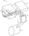
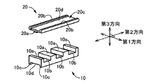
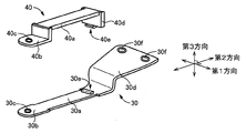
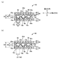
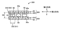
本発明の実施例に係る車両用電気ケーブルの固定装置である中継プロテクタの適用例を説明する図である。It is a figure explaining the example of application of the relay protector which is a fixing device of the electric cable for vehicles concerning the example of the present invention. 図1に示す中継プロテクタの斜視図である。It is a perspective view of the relay protector shown in FIG. 図2に示す中継プロテクタを構成する第1部材及び第2部材の斜視図である。It is a perspective view of the 1st member and the 2nd member which comprise the relay protector shown in FIG. 図2に示す中継プロテクタを構成する第3部材及び第4部材の斜視図である。It is a perspective view of the 3rd member and the 4th member which comprise the relay protector shown in FIG. 図2に示す中継プロテクタ及び車両用電気ケーブルの状態を説明する模式図であって、(a)は車両用電気ケーブルが中継プロテクタの支持部材とカバー部材とで挟持される前の状態(組み立て前の状態)であり、(b)は車両用電気ケーブルが中継プロテクタの支持部材とカバー部材とで挟持された状態(組み立て後の状態)である。It is a schematic diagram explaining the state of the relay protector and the electric cable for vehicles shown in FIG. 2, (a) is a state before the electric cable for vehicles is pinched by the support member and cover member of a relay protector (before assembly). (B) is a state in which the vehicle electric cable is sandwiched between the support member and the cover member of the relay protector (state after assembly). 比較例に係る中継プロテクタ及び車両用電気ケーブルの状態を説明する模式図であって、車両用電気ケーブルが中継プロテクタの支持部材とカバー部材とで挟持された状態(組み立て後の状態)である。It is a schematic diagram explaining the state of the relay protector and the electric cable for vehicles which concerns on a comparative example, and is a state (state after an assembly) in which the electric cable for vehicles was pinched by the support member and cover member of a relay protector.

以下、本発明の実施例について図面を参照しつつ詳細に説明する。なお、以下の実施例において図は理解を容易とするために適宜簡略化或いは変形されており、各部の寸法比および形状等は必ずしも正確に描かれていない。 Hereinafter, embodiments of the present invention will be described in detail with reference to the drawings. In the following examples, the drawings are appropriately simplified or modified for easy understanding, and the dimensional ratios and shapes of the respective parts are not necessarily drawn accurately.

図1は、本発明の実施例に係る車両用電気ケーブル90の固定装置である中継プロテクタ80の適用例を説明する図である。 FIG. 1 is a diagram illustrating an application example of a relay protector 80 that is a fixing device for a vehicle electric cable 90 according to an embodiment of the present invention.

図1に示されているのは、電気自動車100のエンジンルーム内の概略構成である。エンジンルーム内では、不図示のトランスアクスル、インバータ110、電動機130、及び充電器150が互いに締結されている。電気自動車100では、充電器150に充電された直流電力がインバータ110により交流電力に変換され、その変換された交流電力により電動機130が回転駆動される。この電動機130の駆動力が電気自動車100の駆動輪に伝達される。 FIG. 1 shows a schematic configuration in the engine room of the electric vehicle 100. In the engine room, a transaxle (not shown), the inverter 110, the electric motor 130, and the charger 150 are fastened together. In electric vehicle 100, the DC power charged in charger 150 is converted into AC power by inverter 110, and electric motor 130 is rotationally driven by the converted AC power. The driving force of the electric motor 130 is transmitted to the driving wheels of the electric vehicle 100.

インバータ110から電動機130への電力供給は、複数本(本実施例では3本)の車両用電気ケーブル90(以下、「電気ケーブル90」と記す。)を介して行われる。例えば、3本の電気ケーブル90は、U相、V相、及びW相の三相の交流電力の供給を行うものである。3本の電気ケーブル90の一端側は、インバータ側コネクタ120に接続され、それらの他端側は、電動機側コネクタ140に接続されている。インバータ側コネクタ120には、インバータ110内のケーブルが接続され、電動機側コネクタ140には、電動機130内のケーブルが接続されている。これにより、インバータ110から出力された交流電力が、インバータ側コネクタ120、複数本の電気ケーブル90、及び電動機側コネクタ140を介して電動機130に供給される。 Electric power is supplied from the inverter 110 to the electric motor 130 via a plurality (three in this embodiment) of vehicle electric cables 90 (hereinafter, referred to as “electric cables 90”). For example, the three electric cables 90 supply three-phase AC power of U-phase, V-phase, and W-phase. One end sides of the three electric cables 90 are connected to the inverter side connector 120, and the other end sides thereof are connected to the electric motor side connector 140. The cable inside the inverter 110 is connected to the inverter side connector 120, and the cable inside the electric motor 130 is connected to the electric motor side connector 140. As a result, the AC power output from the inverter 110 is supplied to the electric motor 130 via the inverter-side connector 120, the plurality of electric cables 90, and the electric-motor-side connector 140.

3本の電気ケーブル90は、例えばそれぞれ金属線を撚り合せた電線の外周を絶縁性樹脂が用いられて被覆したものである。その両端がインバータ側コネクタ120と電動機側コネクタ140とによって拘束される比較的電線径が太い電気ケーブル90は、たわむことによる周辺部品への接触等の干渉を抑制するために、電気ケーブル90の中間部(すなわち、電気ケーブル90の一端側と他端側との間の部分)が中継プロテクタ80によって保持される。なお、中継プロテクタ80は、本発明における「固定装置」に相当する。 Each of the three electric cables 90 is, for example, a wire formed by twisting metal wires and the outer circumference of the electric wire covered with an insulating resin. The electric cable 90 having a relatively large electric wire diameter whose both ends are bound by the inverter-side connector 120 and the electric motor-side connector 140 has an intermediate portion of the electric cable 90 in order to suppress interference such as contact with peripheral components due to bending. The portion (that is, the portion between the one end side and the other end side of the electric cable 90) is held by the relay protector 80. The relay protector 80 corresponds to the "fixing device" in the present invention.

図2は、図1に示す中継プロテクタ80の斜視図である。図3は、図2に示す中継プロテクタ80を構成する第1部材10及び第2部材20の斜視図である。図4は、図2に示す中継プロテクタ80を構成する第3部材30及び第4部材40の斜視図である。なお、図2、図3、図4、後述の図5、及び後述の図6のそれぞれにおいて示されている第1(幅)方向、第2(長手)方向、及び第3(厚み)方向は、図が異なってもそれぞれ同じ方向である。第1方向及び第2方向は互いに垂直な方向であり、第3方向は第1方向及び第2方向のいずれに対しても垂直な方向である。 FIG. 2 is a perspective view of the relay protector 80 shown in FIG. FIG. 3 is a perspective view of the first member 10 and the second member 20 constituting the relay protector 80 shown in FIG. FIG. 4 is a perspective view of the third member 30 and the fourth member 40 that form the relay protector 80 shown in FIG. Note that the first (width) direction, the second (longitudinal) direction, and the third (thickness) direction shown in FIGS. 2, 3, 4 and FIGS. , The directions are the same even if the figures are different. The first direction and the second direction are directions perpendicular to each other, and the third direction is a direction perpendicular to both the first direction and the second direction.

図2に示すように、中継プロテクタ80は、第1部材10、第2部材20、第3部材30、及び第4部材40を備える。中継プロテクタ80において、第1部材10及び第3部材30が支持部材50を構成し、第2部材20及び第4部材40がカバー部材60を構成する。支持部材50及びカバー部材60は、相対向して電気ケーブル90を挿通させた状態で電気ケーブル90の中間部を挟持する。ここで、支持部材50及びカバー部材60において、電気ケーブル90を挟持した状態における電気ケーブル90側を内側とし、その内側とは反対側を外側ということとする。第1部材10は支持部材50の内側の部材であり、第3部材30は支持部材50の外側の部材である。第2部材20はカバー部材60の内側の部材であり、第4部材40はカバー部材60の外側の部材である。なお、第1部材10及び第3部材30は、それぞれ本発明における「支持部材の内側」及び「支持部材の外側」に相当し、第2部材20及び第4部材40は、それぞれ本発明における「カバー部材の内側」及び「カバー部材の外側」に相当する。 As shown in FIG. 2, the relay protector 80 includes a first member 10, a second member 20, a third member 30, and a fourth member 40. In the relay protector 80, the first member 10 and the third member 30 form the support member 50, and the second member 20 and the fourth member 40 form the cover member 60. The support member 50 and the cover member 60 sandwich the middle portion of the electric cable 90 in a state where the electric cable 90 is inserted so as to face each other. Here, in the support member 50 and the cover member 60, the electric cable 90 side with the electric cable 90 being sandwiched is defined as the inner side, and the side opposite to the inner side is defined as the outer side. The first member 10 is a member inside the support member 50, and the third member 30 is a member outside the support member 50. The second member 20 is a member inside the cover member 60, and the fourth member 40 is a member outside the cover member 60. The first member 10 and the third member 30 correspond to the “inside of the support member” and the “outside of the support member”, respectively, in the present invention, and the second member 20 and the fourth member 40 are respectively “in the present invention”. It corresponds to “the inside of the cover member” and “the outside of the cover member”.

図3に示すように、第1部材10は、全体として第2方向に長手状の部材である。第1部材10は、弾性部材(例えばエチレン・プロピレン・ジエン・ゴムEPDM等のゴム部材)である。なお、弾性部材である第1部材10は、後述する鋼板等の金属製である第3部材30よりも弾性率が小さい。第1部材10の第3方向における内側には、第1方向に伸びる複数の第1突部10aが電気ケーブル90の半径(=直径D0/2)よりも大きく直径D0よりも小さい高さで設けられている(図5参照)。隣接する第1突部10aの間には電気ケーブル90を確実に収容できる溝幅で第1方向に貫通する第1溝部10bが形成され、第1溝部10bは第3方向における内側方向に開口部を有している。第1部材10の第3方向における外側には、第1方向の両端部にそれぞれ第2方向に伸びる第2突部10cが設けられている。この両端部に設けられた第2突部10cの間には第2方向に貫通する第2溝部10dが形成され、第2溝部10dは第3方向における外側方向に開口部を有している。 As shown in FIG. 3, the first member 10 is a member elongated in the second direction as a whole. The first member 10 is an elastic member (for example, a rubber member such as ethylene/propylene/diene/rubber EPDM). The first member 10 that is an elastic member has a smaller elastic modulus than the third member 30 that is made of metal such as a steel plate described below. Inside the first member 10 in the third direction, a plurality of first protrusions 10a extending in the first direction are provided at a height larger than the radius (=diameter D0/2) of the electric cable 90 and smaller than the diameter D0. (See FIG. 5). A first groove portion 10b penetrating in the first direction is formed between adjacent first protrusions 10a with a groove width capable of reliably accommodating the electric cable 90, and the first groove portion 10b has an opening inward in the third direction. have. On the outside of the first member 10 in the third direction, second projecting portions 10c extending in the second direction are provided at both ends in the first direction. A second groove 10d penetrating in the second direction is formed between the second protrusions 10c provided at both ends, and the second groove 10d has an opening in the outer direction in the third direction.

図3に示すように、第2部材20は、全体として第2方向に長手状の部材である。第2部材20は、弾性部材(例えばエチレン・プロピレン・ジエン・ゴムEPDM等のゴム部材)である。なお、弾性部材である第2部材20は、後述する鋼板等の金属製である第4部材40よりも弾性率が小さい。第2部材20の第3方向における内側には、第2方向の両端部にそれぞれ第3方向の内側に突出する第1突部20a(図3では、一端部側の第1突部20aのみが図示されている)が設けられている。第2部材20の第3方向における外側には、第1方向の両端部にそれぞれ第2方向に伸びる第2突部20bが設けられている。この両端部に設けられた第2突部20bの間には第2方向に貫通する溝部20cが形成され、溝部20cは第3方向における外側方向に開口部を有している。第2部材20において、溝部20cの底面を構成して第2方向に伸びている部分が平坦部20dである。 As shown in FIG. 3, the second member 20 is a member elongated in the second direction as a whole. The second member 20 is an elastic member (for example, a rubber member such as ethylene/propylene/diene/rubber EPDM). The second member 20 that is an elastic member has a smaller elastic modulus than the fourth member 40 that is made of metal such as a steel plate described below. Inside the second member 20 in the third direction, the first protrusions 20a protruding inward in the third direction at both ends in the second direction (in FIG. 3, only the first protrusion 20a on the one end side are provided). (Shown). On the outer side of the second member 20 in the third direction, second projecting portions 20b extending in the second direction are provided at both ends in the first direction. A groove 20c penetrating in the second direction is formed between the second protrusions 20b provided at both ends, and the groove 20c has an opening in the outer direction in the third direction. In the second member 20, the flat portion 20d is a portion that constitutes the bottom surface of the groove portion 20c and extends in the second direction.

図4に、第3部材30の斜視図が示されている。第3部材30は、金属製(例えば冷間圧延鋼板等の鋼板)である。例えば、第3部材30は金属板を加工して形成される。第3部材30の第2方向における中央部には、第1部材10の第2溝部10dに対応して嵌込み可能な押さえ部30aが設けられている。押さえ部30aの第2方向の一端側には第1端部30bが設けられ、他端側には第2端部30dが設けられている。押さえ部30aとの接続部分における第1端部30bの第1方向の両端は、押さえ部30aの両端よりも第1方向にそれぞれ伸びている。押さえ部30aとの接続部分における第2端部30dの第1方向の両端は、押さえ部30aの両端よりも第1方向にそれぞれ伸びている。 FIG. 4 shows a perspective view of the third member 30. The third member 30 is made of metal (for example, a steel plate such as a cold rolled steel plate). For example, the third member 30 is formed by processing a metal plate. At the central portion of the third member 30 in the second direction, a pressing portion 30a that can be fitted is provided corresponding to the second groove portion 10d of the first member 10. A first end portion 30b is provided on one end side of the pressing portion 30a in the second direction, and a second end portion 30d is provided on the other end side thereof. Both ends in the first direction of the first end portion 30b at the connecting portion with the holding portion 30a extend in the first direction more than both ends of the holding portion 30a. Both ends of the second end portion 30d in the first direction at the connecting portion with the holding portion 30a extend in the first direction more than both ends of the holding portion 30a.

第1端部30bには、第3方向に貫通する貫通穴30cが1箇所設けられている。第2端部30dの第2方向における中間部において、第2端部30dは第3方向における内側方向に折り曲げられた部分を有する。第2端部30dは、押さえ部30aとの接続部分から第2方向の外方(押さえ部30aとの接続部分とは反対の方向)へ伸びるのに従って第1方向に幅広となっている。第2端部30dにおける折り曲げられた部分よりも第2方向の外方に伸びている部分には、第3方向に貫通するボルト穴30fが2箇所設けられている。このボルト穴30fは、複数本の電気ケーブル90を保持した中継プロテクタ80を非回転部材、例えばトランスアクスルのケースに固定して取り付けるためのボルトを通す穴である。押さえ部30aの第2端部30d側には、被係止部30eが設けられている。 The first end portion 30b is provided with one through hole 30c penetrating in the third direction. In the middle part of the second end 30d in the second direction, the second end 30d has a portion that is bent inward in the third direction. The second end portion 30d becomes wider in the first direction as it extends outward in the second direction from the connection portion with the pressing portion 30a (the direction opposite to the connection portion with the pressing portion 30a). Two bolt holes 30f penetrating in the third direction are provided in a portion of the second end portion 30d extending outward in the second direction from the bent portion. The bolt hole 30f is a hole through which a bolt for fixing the relay protector 80 holding a plurality of electric cables 90 to a non-rotating member such as a transaxle case is inserted. A locked portion 30e is provided on the second end portion 30d side of the pressing portion 30a.

図4に、第4部材40の斜視図が示されている。第4部材40は、金属製(例えば冷間圧延鋼板等の鋼板)である。例えば、第4部材40は金属板を加工して形成される。 FIG. 4 shows a perspective view of the fourth member 40. The fourth member 40 is made of metal (for example, a steel plate such as a cold rolled steel plate). For example, the fourth member 40 is formed by processing a metal plate.

第4部材40には、第2部材20の溝部20cに対応して嵌込み可能な押さえ部40aが設けられている。押さえ部40aの一端側には、第1端部40bが設けられ、他端側には第2端部40dが設けられている。 The fourth member 40 is provided with a holding portion 40a that can be fitted in corresponding to the groove portion 20c of the second member 20. A first end portion 40b is provided on one end side of the pressing portion 40a, and a second end portion 40d is provided on the other end side.

第1端部40bは、押さえ部40aとの接続部分から第3方向における内側方向に折り曲げられた部分及びさらにその折り曲げられた先端から第2方向における外方(押さえ部40aとの接続部分とは反対の方向)へ折り曲げられた部分である。第2端部40dは、押さえ部40aとの接続部分から第3方向における内側方向に折り曲げられた部分及びさらにその折り曲げられた先端に係止部40eが設けられた部分である。後述するように中継プロテクタ80が組み立てられた場合には、第4部材40の係止部40eは第3部材30の被係止部30eに係止可能な構成となっている。押さえ部40aとの接続部分における第1端部40bの第1方向の両端は、押さえ部40aの両端よりも第1方向にそれぞれ伸びている。押さえ部40aとの接続部分における第2端部40dの第1方向の両端は、押さえ部40aの両端よりも第1方向にそれぞれ伸びている。 The first end portion 40b is a portion that is bent inward in the third direction from the connection portion with the holding portion 40a and further outward from the bent tip in the second direction (the connection portion with the holding portion 40a is It is the part that is bent in the opposite direction). The second end portion 40d is a portion that is bent inward in the third direction from a portion that is connected to the holding portion 40a, and a portion that is provided with a locking portion 40e at the bent tip. When the relay protector 80 is assembled as described below, the locking portion 40e of the fourth member 40 is configured to be locked by the locked portion 30e of the third member 30. Both ends of the first end portion 40b in the first direction at the connecting portion with the holding portion 40a extend in the first direction more than both ends of the holding portion 40a. Both ends of the second end portion 40d in the first direction at the connecting portion with the holding portion 40a extend in the first direction more than both ends of the holding portion 40a.

第1端部40bの第2方向における外方へ折り曲げられた部分には、第3方向に貫通する貫通穴40cが1箇所設けられている。後述するように中継プロテクタ80が組み立てられた場合には、第4部材40の貫通穴40cと第3部材30の貫通穴30cとは、第1方向及び第2方向における位置が同じになる。 One through hole 40c penetrating in the third direction is provided in the portion of the first end portion 40b that is bent outward in the second direction. When the relay protector 80 is assembled as described later, the through hole 40c of the fourth member 40 and the through hole 30c of the third member 30 have the same position in the first direction and the second direction.

ここから、中継プロテクタ80の組み立て方法について説明する。まず、第3部材30の押さえ部30aに対して第1部材10の第2溝部10dを嵌め込み、第1部材10に対向させて第2部材20を配置する。さらに、第4部材40の係止部40eを第3部材30の被係止部30eに係止させつつ、第2部材20の溝部20cに対して押さえ部40aを嵌め込み、第4部材40の第1端部40bと第3部材30の第1端部30bとが重なるようにする。第3部材30の貫通穴30cと第4部材40の貫通穴40cとは第1方向及び第2方向における位置が同じであるため、これら貫通穴30c及び貫通穴40cをリベットで固定する。これにより、図2に示す中継プロテクタ80が組み立てられる。なお、実際には、相対向する第1部材10の第1溝部10bと第2部材20の平坦部20dとで囲まれたそれぞれの部分において、3本の電気ケーブル90が第2方向に並べて挿通された状態でそれぞれ挟持されて保持される。なお、第2方向は、本発明における「並列方向」に相当する。 From here, a method of assembling the relay protector 80 will be described. First, the second groove portion 10d of the first member 10 is fitted into the pressing portion 30a of the third member 30, and the second member 20 is arranged so as to face the first member 10. Further, while the locking portion 40e of the fourth member 40 is locked to the locked portion 30e of the third member 30, the pressing portion 40a is fitted into the groove portion 20c of the second member 20, and the fourth member 40 The 1st end 40b and the 1st end 30b of the 3rd member 30 are made to overlap. Since the through hole 30c of the third member 30 and the through hole 40c of the fourth member 40 have the same position in the first direction and the second direction, the through hole 30c and the through hole 40c are fixed with rivets. As a result, the relay protector 80 shown in FIG. 2 is assembled. Note that, in reality, three electric cables 90 are inserted side by side in the second direction at respective portions surrounded by the first groove portion 10b of the first member 10 and the flat portion 20d of the second member 20 which face each other. Each of them is clamped and held in the pressed state. The second direction corresponds to the "parallel direction" in the present invention.

組み立て後の状態において、第1部材10の第1方向への移動は、押さえ部30aの第1部材10の第2溝部10dへの嵌め込みにより制限され、第1部材10の第2方向への移動は、第1端部30b及び第2端部30dの押さえ部30aとの接続部分における第1方向に伸びている部分がそれぞれ第1部材10の第2突部10cを第2方向で挟んでいるため制限される。組み立て後の状態において、第2部材20の第1方向への移動は、押さえ部40aの第2部材20の溝部20cへの嵌め込みにより制限され、第2部材20の第2方向への移動は、第1端部40b及び第2端部40dの押さえ部40aとの接続部分における第1方向に伸びている部分がそれぞれ第2部材20の第2突部20bを第2方向で挟んでいるため制限される。 In the assembled state, the movement of the first member 10 in the first direction is limited by the fitting of the pressing portion 30a into the second groove 10d of the first member 10, and the movement of the first member 10 in the second direction. In the connecting portions of the first end portion 30b and the second end portion 30d with the holding portion 30a, the portions extending in the first direction sandwich the second protrusion 10c of the first member 10 in the second direction. Therefore, it is limited. In the state after assembly, the movement of the second member 20 in the first direction is limited by the fitting of the pressing portion 40a into the groove portion 20c of the second member 20, and the movement of the second member 20 in the second direction is Limitation because the portions of the first end portion 40b and the second end portion 40d that connect to the holding portion 40a extend in the first direction sandwich the second protrusion 20b of the second member 20 in the second direction. To be done.

図5は、図2に示す中継プロテクタ80及び電気ケーブル90の状態を説明する模式図であって、(a)は電気ケーブル90が中継プロテクタ80の支持部材50とカバー部材60とで挟持される前の状態(組み立て前の状態)であり、(b)は電気ケーブル90が中継プロテクタ80の支持部材50とカバー部材60とで挟持された状態(組み立て後の状態)である。図5は、図2に示す第1方向から見た電気ケーブル90及び中継プロテクタ80の断面図である。 FIG. 5 is a schematic diagram for explaining the states of the relay protector 80 and the electric cable 90 shown in FIG. 2. In FIG. 5A, the electric cable 90 is sandwiched between the support member 50 and the cover member 60 of the relay protector 80. It is a previous state (state before assembly), and (b) is a state in which the electric cable 90 is sandwiched between the support member 50 and the cover member 60 of the relay protector 80 (state after assembly). FIG. 5 is a cross-sectional view of the electric cable 90 and the relay protector 80 as seen from the first direction shown in FIG.

図5(a)に示すように、電気ケーブル90が中継プロテクタ80の支持部材50とカバー部材60とで挟持される前の状態では、断面が直径D0[mm]の円形の3本の電気ケーブル90が第1部材10における溝幅W[mm](>D0)の第1溝部10bにそれぞれ嵌め入れられている。電気ケーブル90の直径D0は、第3方向における第1部材10の第1突部10aの高さH1[mm]と第2部材20の第1突部20aの高さH2[mm]との合計値よりも大きい。そのため、第2方向における両端部での第1突部10aと第1突部20aとの間には隙間がある。第1突部10aの高さH1は、電気ケーブル90の直径D0よりも小さく、半径(=D0/2)よりも大きい。第3方向において、第1部材10の外側には第3部材30の押さえ部30aがあり、第2部材20の外側には第4部材40の押さえ部40aがある。 As shown in FIG. 5A, in the state before the electric cable 90 is sandwiched between the support member 50 and the cover member 60 of the relay protector 80, three electric cables having a circular cross section with a diameter D0 [mm] are provided. 90 are respectively fitted in the first groove portions 10b having the groove width W [mm] (>D0) in the first member 10. The diameter D0 of the electric cable 90 is the sum of the height H1 [mm] of the first protrusion 10a of the first member 10 and the height H2 [mm] of the first protrusion 20a of the second member 20 in the third direction. Greater than value. Therefore, there is a gap between the first protrusion 10a and the first protrusion 20a at both ends in the second direction. The height H1 of the first protrusion 10a is smaller than the diameter D0 of the electric cable 90 and larger than the radius (=D0/2). In the third direction, the holding portion 30a of the third member 30 is located outside the first member 10, and the holding portion 40a of the fourth member 40 is located outside the second member 20.

図5(b)に示すように、電気ケーブル90が中継プロテクタ80の支持部材50とカバー部材60とで挟持された状態では、第3方向における第1溝部10bの底面と平坦部20dとの間の隙間の距離G1[mm]は、金属である押さえ部30a及び押さえ部40aによる第3方向における隙間の距離G0[mm]に応じて変化する。隙間の距離G1が、第1突部10aの高さH1と第1突部20aの高さH2との合計値よりも小さい場合には、第2方向の両端部における第1突部10a及び第1突部20aは、押さえ部30a及び押さえ部40aにより第3方向に押しつぶされた状態となっている。隙間の距離G1の大きさに応じて、第1部材10及び第2部材20が電気ケーブル90を挟持する押圧力が変化する。 As shown in FIG. 5B, when the electric cable 90 is sandwiched between the support member 50 and the cover member 60 of the relay protector 80, between the bottom surface of the first groove portion 10b and the flat portion 20d in the third direction. The distance G1 [mm] of the gap changes according to the distance G0 [mm] of the gap in the third direction by the metal pressing part 30a and the pressing part 40a. When the gap distance G1 is smaller than the sum of the height H1 of the first protrusion 10a and the height H2 of the first protrusion 20a, the first protrusion 10a and the first protrusion 10a at both ends in the second direction The first protrusion 20a is in a state of being crushed in the third direction by the holding portion 30a and the holding portion 40a. The pressing force with which the first member 10 and the second member 20 clamp the electric cable 90 changes according to the size of the gap distance G1.

図5(b)に示すように、電気ケーブル90は、第1部材10及び第2部材20により押圧されることで変形する。電気ケーブル90の断面は円形から楕円形に変形し、第2方向の長径(長軸の長さ)D1[mm]が直径D0よりも大きくなり、第3方向の短径(短軸の長さ)D2[mm]が直径D0よりも小さくなる。電気ケーブル90の断面について第2方向の長径D1が大きくなることが電気ケーブル90の第2方向における両側に配設された第1突部10aによって抑制されるため、第2方向の長径D1は第1溝部10bの溝幅Wに制限される。言い換えると、第1部材10には、電気ケーブル90のそれぞれを第2方向における両側から挟むことにより電気ケーブル90の変形を抑制する相対向する第1突部10aが設けられている。なお、第1部材10の内側に設けられた第1突部10aは、本発明における「仕切部」に相当する。 As shown in FIG. 5B, the electric cable 90 is deformed by being pressed by the first member 10 and the second member 20. The cross section of the electric cable 90 is changed from a circular shape to an elliptical shape, the major axis (length of the major axis) D1 [mm] in the second direction becomes larger than the diameter D0, and the minor axis (length of the minor axis) in the third direction. ) D2 [mm] becomes smaller than the diameter D0. The increase in the major axis D1 in the second direction with respect to the cross section of the electric cable 90 is suppressed by the first protrusions 10a arranged on both sides of the electric cable 90 in the second direction. It is limited to the groove width W of the one groove portion 10b. In other words, the first member 10 is provided with the first protrusions 10a that face each other and that suppress the deformation of the electric cable 90 by sandwiching the electric cable 90 from both sides in the second direction. The first protrusion 10a provided inside the first member 10 corresponds to the "partitioning portion" in the present invention.

電気ケーブル90の断面について第2方向の長径D1が大きくなることが抑制されるため、電気ケーブル90の断面について第3方向の短径D2が小さくなることが抑制され、第3方向の短径D2は隙間の距離G1よりも大きくされる。このため、電気ケーブル90は、第3方向において弾性部材である第2部材20の平坦部20dに食い込む。これにより、電気ケーブル90は、第3方向において弾性部材である第1部材10の第1溝部10bの底面と第2部材20の平坦部20dとにより押圧された状態で挟持されて保持される。なお、第3方向において、弾性部材である第1部材10は金属である第3部材30の押さえ部30aにより押さえられており、弾性部材である第2部材20は金属である第4部材40の押さえ部40aにより押さえられている。そのため、弾性部材である第1部材10及び第2部材20がそれぞれ外側に向かって変形することが押さえ部30a及び押さえ部40aにより抑制され、押さえ部30a及び押さえ部40aが無い場合に比較して、電気ケーブル90に対する保持力(押圧力)が低下することが抑制される。 Since the major axis D1 in the second direction in the cross section of the electric cable 90 is suppressed from increasing, the minor axis D2 in the third direction in the cross section of the electric cable 90 is suppressed from decreasing, and the minor axis D2 in the third direction is suppressed. Is larger than the gap distance G1. Therefore, the electric cable 90 bites into the flat portion 20d of the second member 20 that is the elastic member in the third direction. As a result, the electric cable 90 is clamped and held in the third direction while being pressed by the bottom surface of the first groove portion 10b of the first member 10 which is an elastic member and the flat portion 20d of the second member 20. In the third direction, the first member 10, which is an elastic member, is pressed by the pressing portion 30a of the third member 30, which is a metal, and the second member 20, which is an elastic member, of the fourth member 40, which is a metal. It is held by the holding portion 40a. Therefore, the first member 10 and the second member 20, which are elastic members, are prevented from being deformed outward, respectively, by the holding portion 30a and the holding portion 40a, and compared with the case where the holding portion 30a and the holding portion 40a are not provided. The reduction of the holding force (pressing force) on the electric cable 90 is suppressed.

図5(b)では、理解を容易とするために意図的に電気ケーブル90の断面が楕円形に変形して第2部材20の平坦部20dにのみ食い込むように示して説明されている。しかし、実際には、第1部材10の第1突部10a(すなわち第1溝部10bの側壁)及び第1溝部10bの底面の弾性率と第2部材20の平坦部20dの弾性率とに応じて、電気ケーブル90の断面は厳密には完全な楕円形には変形せず、また第2部材20の平坦部20dの他、第1部材10の第1突部10a及び第1溝部10bの底面にも食い込み得る。 In FIG. 5B, for easy understanding, the cross section of the electric cable 90 is intentionally deformed into an elliptical shape so as to bite only into the flat portion 20 d of the second member 20. However, in reality, depending on the elastic modulus of the first protrusion 10a of the first member 10 (that is, the side wall of the first groove portion 10b) and the bottom surface of the first groove portion 10b and the elastic modulus of the flat portion 20d of the second member 20, Strictly speaking, the cross section of the electric cable 90 does not deform into a perfect elliptical shape, and the flat surface 20d of the second member 20 as well as the bottom surfaces of the first protrusion 10a and the first groove portion 10b of the first member 10 are formed. You can also cut into.

図6は、比較例に係る中継プロテクタ280及び電気ケーブル90の状態を説明する模式図であって、電気ケーブル90が中継プロテクタ280の支持部材250とカバー部材260とで挟持された状態(組み立て後の状態)である。 FIG. 6 is a schematic diagram illustrating the states of the relay protector 280 and the electric cable 90 according to the comparative example, in which the electric cable 90 is sandwiched between the support member 250 and the cover member 260 of the relay protector 280 (after assembly). State).

比較例に係る中継プロテクタ280の構成は、本実施例に係る中継プロテクタ80の構成と略同じであるが、中継プロテクタ80では電気ケーブル90の変形を抑制する第1突部10aがあったのに対し、中継プロテクタ280では第1突部10aがない点が異なる。そのため、中継プロテクタ280が中継プロテクタ80と共通する部分には同一の符号を付して説明を適宜省略する。 The configuration of the relay protector 280 according to the comparative example is substantially the same as the configuration of the relay protector 80 according to the present embodiment, but the relay protector 80 has the first protrusion 10a that suppresses the deformation of the electric cable 90. On the other hand, the relay protector 280 is different in that the first protrusion 10a is not provided. Therefore, the parts in which the relay protector 280 and the relay protector 80 are common are given the same reference numerals, and the description thereof will be appropriately omitted.

中継プロテクタ280は、第1部材210、第2部材220、第3部材30、及び第4部材40を備える。中継プロテクタ280において、第1部材210及び第3部材30が支持部材250を構成し、第2部材220及び第4部材40がカバー部材260を構成する。第1部材210の構成は、前述の第1部材10の構成と略同じであるが、第1部材210では第1突部10aが無い。第2部材220の構成は、前述の第2部材20の構成と略同じであるが、第2部材220では第1突部20aが無い。 The relay protector 280 includes a first member 210, a second member 220, a third member 30, and a fourth member 40. In the relay protector 280, the first member 210 and the third member 30 form the support member 250, and the second member 220 and the fourth member 40 form the cover member 260. The configuration of the first member 210 is substantially the same as the configuration of the first member 10 described above, but the first member 210 does not have the first protrusion 10a. The configuration of the second member 220 is substantially the same as the configuration of the second member 20 described above, but the second member 220 does not have the first protrusion 20a.

図6に示すように、電気ケーブル90が中継プロテクタ280の支持部材250とカバー部材260とで挟持された状態において、前述の図5(b)との比較のため、第3方向における第1部材210と第2部材220との間の隙間の距離G1は図5(b)と同じである。電気ケーブル90は、第1部材210及び第2部材220により押圧された状態で挟持されて保持される。しかし、時間の経過とともに電気ケーブル90が弾性部材である第1部材210及び第2部材220から押圧力を受け続けることにより電気ケーブル90の絶縁性樹脂が塑性変形し、電気ケーブル90の断面は、第2方向の長径D3[mm]が前述の長径D1よりも大きく、第3方向の短径D4[mm]が前述の短径D2よりも小さな楕円形になる。 As shown in FIG. 6, in a state where the electric cable 90 is sandwiched between the support member 250 and the cover member 260 of the relay protector 280, the first member in the third direction is compared for comparison with FIG. 5B described above. The gap distance G1 between 210 and the second member 220 is the same as in FIG. 5(b). The electric cable 90 is sandwiched and held while being pressed by the first member 210 and the second member 220. However, as the electric cable 90 continues to receive a pressing force from the first member 210 and the second member 220, which are elastic members, over time, the insulating resin of the electric cable 90 plastically deforms, and the cross section of the electric cable 90 becomes The major axis D3 [mm] in the second direction is larger than the major axis D1 and the minor axis D4 [mm] in the third direction is smaller than the minor axis D2.

これは、第1突部10aが無いために、電気ケーブル90の断面について第2方向の長径D3が溝幅Wよりも大きくなることが抑制されず、そのため電気ケーブル90の断面について第3方向の短径D4が小さくなることが抑制されないからである。電気自動車100のようにインバータ110から電動機130へ供給される交流電力が大きい場合には、供給電力による電気ケーブル90内の電線の発熱量を抑制するために電気ケーブル90内の電線が太くされる。このように電線が太くされるほど、すなわち電気ケーブル90の直径D0が大きくされるほど、電気ケーブル90が押さえられた場合に電気ケーブル90の断面が楕円形に変形しやすくなって電気ケーブル90の第3方向における径が小さくなり、絶縁性樹脂の厚みが減少する。これにより、弾性部材である第1部材210と第2部材220とによる中継プロテクタ280の電気ケーブル90に対する保持力(押圧力)が前述した中継プロテクタ80の場合よりも低下してしまう。 This is because it is not possible to prevent the major axis D3 in the second direction in the cross section of the electric cable 90 from becoming larger than the groove width W because the first protrusion 10a is not provided, and therefore, in the cross section of the electric cable 90 in the third direction. This is because the reduction of the minor axis D4 is not suppressed. When the AC power supplied from the inverter 110 to the electric motor 130 is large as in the electric vehicle 100, the electric wire in the electric cable 90 is thickened in order to suppress the heat generation amount of the electric wire in the electric cable 90 due to the supplied electric power. Thus, the thicker the electric wire, that is, the larger the diameter D0 of the electric cable 90, the more easily the electric cable 90 is deformed into an elliptical cross section when the electric cable 90 is pressed. The diameter in the three directions is reduced, and the thickness of the insulating resin is reduced. As a result, the holding force (pressing force) of the relay protector 280 against the electric cable 90 by the first member 210 and the second member 220, which are elastic members, becomes lower than that of the relay protector 80 described above.

なお、図6においても、図5(b)と同様に理解を容易とするために意図的に電気ケーブル90の断面が楕円形に変形するように示して説明されているが、電気ケーブル90の断面は厳密には完全な楕円形には変形しない。 Note that, in FIG. 6 as well, the cross section of the electric cable 90 is intentionally deformed into an elliptical shape for ease of understanding in the same manner as in FIG. Strictly speaking, the cross section does not deform into a perfect ellipse.

本実施例の中継プロテクタ80によれば、支持部材50における内側の第1部材10及びカバー部材60における内側の第2部材20はそれぞれ弾性部材であり、支持部材50における外側の第3部材30及びカバー部材60における外側の第4部材40はそれぞれ金属である。支持部材50の内側の第1部材10には、電気ケーブル90を第2方向における両側から挟むことにより電気ケーブル90の変形を抑制する相対向する第1突部10aが設けられている。 According to the relay protector 80 of the present embodiment, the inner first member 10 of the support member 50 and the inner second member 20 of the cover member 60 are elastic members, and the outer third member 30 of the support member 50 and The outer fourth member 40 of the cover member 60 is made of metal. The first member 10 on the inner side of the support member 50 is provided with the first protrusions 10 a that face each other and that suppress the deformation of the electric cable 90 by sandwiching the electric cable 90 from both sides in the second direction.

支持部材50において外側の金属である第3部材30が内側の弾性部材である第1部材10を内側に向けて押さえており、カバー部材60において外側の金属である第4部材40が内側の弾性部材である第2部材20を内側に向けて押さえているため、第1部材10及び第2部材20による電気ケーブル90に対する保持力の低下が抑制される。 In the support member 50, the third member 30, which is the outer metal, holds the first member 10, which is the inner elastic member, toward the inner side, and in the cover member 60, the fourth member 40, which is the outer metal, has the inner elasticity. Since the second member 20, which is a member, is pressed inward, a decrease in the holding force of the first member 10 and the second member 20 with respect to the electric cable 90 is suppressed.

また、弾性部材である第1部材10に設けられた隣接する第1突部10aの間に形成されたそれぞれの第1溝部10bに3本の電気ケーブル90がそれぞれ挿通され、電気ケーブル90を第2方向における両側から挟む相対向する第1突部10aによって電気ケーブル90の変形(断面の円形から楕円形への変形)が抑制される。電気ケーブル90の変形が抑制されるため、第1突部10aが設けられず電気ケーブル90の変形が抑制されていない場合に比較して、相対向する弾性部材である第1部材10及び第2部材20による電気ケーブル90に対する保持力の低下が抑制される。弾性部材である第1部材10及び第2部材20は、電気ケーブル90の振動を吸収する。したがって、電気ケーブル90に対して振動が発生した場合でも弾性部材である第1部材10及び第2部材20によってその振動が吸収されて電気ケーブル90へのダメージが低減されるとともに、電気ケーブル90の変形が抑制されて第1部材10及び第2部材20による電気ケーブル90に対する保持力の低下が抑制される。 Further, the three electric cables 90 are respectively inserted into the respective first groove portions 10b formed between the adjacent first protrusions 10a provided on the first member 10 which is an elastic member, and the electric cables 90 are connected to each other. Deformation of the electric cable 90 (deformation from a circular cross section to an ellipse) is suppressed by the first protrusions 10 a that face each other and are sandwiched from both sides in the two directions. Since the deformation of the electric cable 90 is suppressed, the first member 10 and the second member, which are elastic members facing each other, are compared to the case where the deformation of the electric cable 90 is not suppressed because the first protrusion 10a is not provided. The reduction in the holding force of the member 20 with respect to the electric cable 90 is suppressed. The first member 10 and the second member 20, which are elastic members, absorb the vibration of the electric cable 90. Therefore, even when vibration is generated in the electric cable 90, the vibration is absorbed by the first member 10 and the second member 20 which are elastic members, and the damage to the electric cable 90 is reduced, and the electric cable 90 The deformation is suppressed, and the reduction in the holding force of the first member 10 and the second member 20 with respect to the electric cable 90 is suppressed.

本実施例の中継プロテクタ80によれば、第3部材30の押さえ部30a及び第4部材40の押さえ部40aによる第3方向における隙間の距離G0[mm]が調整されることで、第3方向における第1溝部10bの底面と平坦部20dとの間の隙間の距離G1が簡便に変更できる。この隙間の距離G1の大きさの変更により、第1部材10及び第2部材20が電気ケーブル90を挟持する押圧力が調整可能である。 According to the relay protector 80 of the present embodiment, by adjusting the distance G0 [mm] of the gap in the third direction by the holding portion 30a of the third member 30 and the holding portion 40a of the fourth member 40, the third direction. The gap distance G1 between the bottom surface of the first groove portion 10b and the flat portion 20d can be easily changed. By changing the size of the gap distance G1, the pressing force with which the first member 10 and the second member 20 clamp the electric cable 90 can be adjusted.

以上、本発明の実施例を図面に基づいて詳細に説明したが、本発明はその他の態様においても適用される。 Although the embodiments of the present invention have been described in detail with reference to the drawings, the present invention can be applied to other aspects.

前述の実施例では、仕切部として機能するのは第1部材10に設けられた第1突部10aであったが、これに限らない。例えば、第2部材20の平坦部20dの第3方向における内側に仕切部として機能する突部が設けられても良い。また、第1部材10に仕切部として機能する第1突部10aが設けられるとともに、第2部材20の平坦部20dの第3方向における内側にも仕切部として機能する突部が設けられても良い。すなわち、支持部材50の内側にある第1部材10及びカバー部材60の内側にある第2部材20の少なくとも一方の第3方向における内側に、電気ケーブル90を第2方向における両側から挟むことにより電気ケーブル90の変形を抑制する相対向する仕切部として機能する突部が設けられれば良い。 In the above-described embodiment, it is the first protrusion 10a provided on the first member 10 that functions as the partition portion, but the present invention is not limited to this. For example, a protrusion functioning as a partition may be provided inside the flat portion 20d of the second member 20 in the third direction. Further, the first member 10 may be provided with the first protrusion 10a that functions as a partition, and the protrusion that functions as the partition may be provided inside the flat portion 20d of the second member 20 in the third direction. good. That is, by sandwiching the electric cable 90 from both sides in the second direction to the inside of the first member 10 inside the support member 50 and the second member 20 inside the cover member 60 in the third direction, electricity is generated. It suffices if projections that function as partitioning sections that oppose each other and that suppress deformation of the cable 90 are provided.

前述の実施例では、第1部材10における第1溝部10bの溝幅Wは、挟持される前の電気ケーブル90の断面の直径D0よりも大きかったが、これに限らない。電気ケーブル90の絶縁性樹脂の塑性変形を考慮して第1溝部10bに電気ケーブル90を嵌め入れることが可能であれば、第1溝部10bの溝幅Wは電気ケーブル90の断面の直径D0と同じでも良いし、第1溝部10bの溝幅Wが電気ケーブル90の断面の直径D0よりも少し小さくても良い。 In the above-described embodiment, the groove width W of the first groove portion 10b of the first member 10 was larger than the diameter D0 of the cross section of the electric cable 90 before being clamped, but it is not limited to this. If the electric cable 90 can be fitted into the first groove portion 10b in consideration of the plastic deformation of the insulating resin of the electric cable 90, the groove width W of the first groove portion 10b is equal to the diameter D0 of the cross section of the electric cable 90. The width W of the first groove portion 10b may be the same or may be slightly smaller than the diameter D0 of the cross section of the electric cable 90.

前述の実施例では、第1方向及び第2方向は互いに垂直な方向であったが、これに限らない。第1方向及び第2方向は互いに交差する方向であれば良い。 Although the first direction and the second direction are perpendicular to each other in the above-described embodiment, the present invention is not limited to this. The first direction and the second direction may be directions that intersect with each other.

前述の実施例では、第3部材30の貫通穴30c及び第4部材40の貫通穴40cはリベットで固定されていたが、これに限らない。例えば、ボルト、溶接、接着剤など他の固定方法でも良い。 In the above-described embodiment, the through hole 30c of the third member 30 and the through hole 40c of the fourth member 40 are fixed with rivets, but the invention is not limited to this. For example, other fixing methods such as bolts, welding, and adhesive may be used.

前述の実施例では、本発明に係る中継プロテクタ80は電気自動車100に適用されたが、これに限らない。例えば、本発明は、内燃機関であるエンジンと電動機との両方を備えたハイブリッド車両に適用されても良い。 Although the relay protector 80 according to the present invention is applied to the electric vehicle 100 in the above-described embodiment, the present invention is not limited to this. For example, the present invention may be applied to a hybrid vehicle that includes both an engine that is an internal combustion engine and an electric motor.

なお、上述したのはあくまでも本発明の実施例であり、本発明はその趣旨を逸脱しない範囲において当業者の知識に基づいて種々の変更、改良を加えた態様で実施することができる。 It should be noted that what has been described above is merely an embodiment of the present invention, and the present invention can be implemented in various modified and improved modes based on the knowledge of those skilled in the art without departing from the spirit of the present invention.

10:第1部材(支持部材の内側)
10a:第1突部(仕切部)
20:第2部材(カバー部材の内側)
30:第3部材(支持部材の外側)
40:第4部材(カバー部材の外側)
50:支持部材
60:カバー部材
80:中継プロテクタ(固定装置)
90:車両用電気ケーブル
10: First member (inside the support member)
10a: first protrusion (partition)
20: Second member (inside the cover member)
30: Third member (outside the support member)
40: Fourth member (outside the cover member)
50: Support member 60: Cover member 80: Relay protector (fixing device)
90: Electric cable for vehicle

Claims (1)

複数本の車両用電気ケーブルを並列方向に並べて挿通させた状態で挟持する相対向する支持部材及びカバー部材を備える車両用電気ケーブルの固定装置であって、
前記支持部材及び前記カバー部材の内側はそれぞれ弾性部材であり、前記支持部材及び前記カバー部材の外側はそれぞれ金属であり、
前記支持部材及び前記カバー部材の少なくとも一方の前記内側には、前記複数本の車両用電気ケーブルを前記並列方向における両側から挟む相対向する仕切部が設けられ、前記相対向する仕切部は前記複数本の車両用電気ケーブルの変形を抑制する
ことを特徴とする車両用電気ケーブルの固定装置。
A fixing device for a vehicle electric cable, comprising: a support member and a cover member that face each other and sandwich a plurality of electric cables for a vehicle arranged in a parallel direction and inserted.
Inner sides of the support member and the cover member are elastic members, and outer sides of the support member and the cover member are metal, respectively.
Inside at least one of the support member and the cover member, facing partition parts that sandwich the plurality of vehicle electric cables from both sides in the parallel direction are provided, and the facing partition parts are the plurality of partition parts. A fixing device for an electric cable for a vehicle, which suppresses deformation of a book electric cable for a vehicle.
JP2019016424A 2019-01-31 2019-01-31 Fixing device for electric cables for vehicles Pending JP2020121702A (en)

Priority Applications (2)

Application Number Priority Date Filing Date Title
JP2019016424A JP2020121702A (en) 2019-01-31 2019-01-31 Fixing device for electric cables for vehicles
CN201911371450.0A CN111509631A (en) 2019-01-31 2019-12-27 Fixtures for cables for vehicles

Applications Claiming Priority (1)

Application Number Priority Date Filing Date Title
JP2019016424A JP2020121702A (en) 2019-01-31 2019-01-31 Fixing device for electric cables for vehicles

Publications (1)

Publication Number Publication Date
JP2020121702A true JP2020121702A (en) 2020-08-13

Family

ID=71874030

Family Applications (1)

Application Number Title Priority Date Filing Date
JP2019016424A Pending JP2020121702A (en) 2019-01-31 2019-01-31 Fixing device for electric cables for vehicles

Country Status (2)

Country Link
JP (1) JP2020121702A (en)
CN (1) CN111509631A (en)

Citations (3)

* Cited by examiner, † Cited by third party
Publication number Priority date Publication date Assignee Title
JPS59101081U (en) * 1982-12-27 1984-07-07 ダイハツ工業株式会社 Clamp for piping/wiring
JPH0350917U (en) * 1989-09-26 1991-05-17
JP2012100470A (en) * 2010-11-04 2012-05-24 Hitachi Cable Ltd Cable clamp

Family Cites Families (6)

* Cited by examiner, † Cited by third party
Publication number Priority date Publication date Assignee Title
CN201708492U (en) * 2009-12-25 2011-01-12 上海捷能汽车技术有限公司 High voltage cables protection device
JP6139109B2 (en) * 2012-11-15 2017-05-31 矢崎総業株式会社 Wire holding structure
JP2016046943A (en) * 2014-08-25 2016-04-04 住友電装株式会社 Protector
JP2017004886A (en) * 2015-06-15 2017-01-05 住友電装株式会社 Protector and wire harness
JP6681026B2 (en) * 2016-11-18 2020-04-15 住友電装株式会社 Protector and wire harness
CN208433717U (en) * 2018-08-02 2019-01-25 任丘市星宇汽车配件有限公司 Plug-type Fast Installation line code

Patent Citations (3)

* Cited by examiner, † Cited by third party
Publication number Priority date Publication date Assignee Title
JPS59101081U (en) * 1982-12-27 1984-07-07 ダイハツ工業株式会社 Clamp for piping/wiring
JPH0350917U (en) * 1989-09-26 1991-05-17
JP2012100470A (en) * 2010-11-04 2012-05-24 Hitachi Cable Ltd Cable clamp

Also Published As

Publication number Publication date
CN111509631A (en) 2020-08-07

Similar Documents

Publication Publication Date Title
US20090108688A1 (en) Connecting structure for connecting electrical apparatus and feeder terminal portion, and vehicle
JP5410543B2 (en) Inverter terminal block
WO2008007806A1 (en) Motor module
EP2136448B1 (en) Fixing tool of wire harness
JP7004178B2 (en) Clamps and wire harnesses with clamps
JP2013247818A (en) Wire harness routing structure
WO2022009964A1 (en) Connector
JP2016088269A (en) Mounting structure for vehicle wire harness
JP6025335B2 (en) Wire connection structure and wire connection method
JP6547178B2 (en) Noise absorber mounting structure
CN111509631A (en) Fixtures for cables for vehicles
JP7226135B2 (en) Vehicle cable mounting structure
JP6398305B2 (en) Bracket for vehicle
US12476498B2 (en) Stator for rotary electric machine
JP2007014090A (en) High-voltage harness wiring structure for electric vehicles
JP2006349087A (en) Seal structure of cable insertion part
JP2005229753A (en) Motor module
JP7509098B2 (en) Charging connector
JP2012100470A (en) Cable clamp
JP7272133B2 (en) Vehicle cable mounting structure
JP2013090452A (en) Protector for polyphase cable
JP7140029B2 (en) In-vehicle structure of power converter
KR101241172B1 (en) Structure for connecting high tension cable
WO2026037636A1 (en) Cover for an electric drivetrain system
JP2026067626A (en) electric vehicle drive unit

Legal Events

Date Code Title Description
A621 Written request for application examination

Free format text: JAPANESE INTERMEDIATE CODE: A621

Effective date: 20210312

A977 Report on retrieval

Free format text: JAPANESE INTERMEDIATE CODE: A971007

Effective date: 20220209

A131 Notification of reasons for refusal

Free format text: JAPANESE INTERMEDIATE CODE: A131

Effective date: 20220222

A02 Decision of refusal

Free format text: JAPANESE INTERMEDIATE CODE: A02

Effective date: 20220823