JP2020122437A - Compressor, and device and refrigerator having the same - Google Patents
Compressor, and device and refrigerator having the same Download PDFInfo
- Publication number
- JP2020122437A JP2020122437A JP2019014997A JP2019014997A JP2020122437A JP 2020122437 A JP2020122437 A JP 2020122437A JP 2019014997 A JP2019014997 A JP 2019014997A JP 2019014997 A JP2019014997 A JP 2019014997A JP 2020122437 A JP2020122437 A JP 2020122437A
- Authority
- JP
- Japan
- Prior art keywords
- fastener
- vibration
- compressor
- vibration isolator
- diameter
- Prior art date
- Legal status (The legal status is an assumption and is not a legal conclusion. Google has not performed a legal analysis and makes no representation as to the accuracy of the status listed.)
- Pending
Links
Images

Landscapes
- Vibration Prevention Devices (AREA)
- Compressor (AREA)
Abstract
【課題】低速後負荷運転時に特に発生する騒音を低減する。【解決手段】内部に振動源を含み、環状の被取付部11を有する密閉容器と、被取付部11に取付けられた弾性を有する防振材3と、締結具4とを備え、防振材3は、締結具4の外径に等しい又はやや小さい径の狭空隙31を有し、狭空隙31は締結具4の外径R1よりやや小さい径であり、締結具4が狭空隙31に挿通されると、防振材3のうち狭空隙31を囲む部分が外径側に弾性変形する圧縮機。【選択図】図4PROBLEM TO BE SOLVED: To reduce noise particularly generated during low-speed afterload operation. SOLUTION: The vibration-proof material is provided with a closed container containing a vibration source inside and having an annular attached portion 11, an elastic anti-vibration material 3 attached to the attached portion 11, and a fastener 4. Reference numeral 3 has a narrow gap 31 having a diameter equal to or slightly smaller than the outer diameter of the fastener 4, the narrow gap 31 having a diameter slightly smaller than the outer diameter R1 of the fastener 4, and the fastener 4 is inserted into the narrow gap 31. Then, the portion of the anti-vibration material 3 that surrounds the narrow gap 31 is elastically deformed to the outer diameter side. [Selection diagram] FIG. 4
Description
本発明は、圧縮機及びこれを有する機器及び冷蔵庫に関する。 The present invention relates to a compressor, a device including the compressor, and a refrigerator.
近年、冷蔵庫では、主に冷凍温度帯の冷気を生成する蒸発器と冷蔵温度帯の冷気を生成する蒸発器とを搭載することが提案されている。これにより冷蔵温度帯の冷気を生成する蒸発器では、比較的高温(すなわち高密度)の冷媒がサイクルを流れて圧縮機に吸い込まれる。したがってピストンによって圧縮する際の負荷が大きく、振動源になりやすい。また同様に近年、圧縮機の低速化が進行している。すなわちピストンの運動における慣性が低下してきており、高負荷である冷媒の圧縮過程と低負荷である冷媒の吸込み過程とで負荷変動が大きく、これによりピストンの速度脈動が大きくなってきている。これらが合わさった結果、従来では想定されていなかった振動源(騒音源)が現れる(目立つ)ようになってきている。 In recent years, it has been proposed that a refrigerator mainly includes an evaporator that generates cold air in the freezing temperature range and an evaporator that generates cold air in the refrigeration temperature range. As a result, in the evaporator that produces cold air in the refrigeration temperature range, a relatively high temperature (that is, high density) refrigerant flows through the cycle and is sucked into the compressor. Therefore, the load when compressed by the piston is large, and it easily becomes a vibration source. Similarly, in recent years, the speed of the compressor has been reduced. That is, the inertia in the movement of the piston is decreasing, and the load fluctuation is large during the compression process of the refrigerant having a high load and the suction process of the refrigerant having a low load, which increases the speed pulsation of the piston. As a result of the combination of these, a vibration source (noise source) that has not been assumed in the past appears (is conspicuous).
さて、圧縮機を床面等に固定する技術に関して、特許文献1は、ボルト65を囲うようにマウントゴム63より硬いカラー部材70を配置し、ボルト65のねじ部65Aの径よりも僅かに大きい径に形成されて当該ボルト65のねじ部65Aが遊嵌される構成を開示する(0008,0016、図3)。
Now, regarding the technique of fixing the compressor to the floor surface or the like, in
本発明者らによれば、近年のピストンの高負荷化や低慣性化が進行すると、特許文献1のマウントゴム63に相当する領域から騒音が発生することが見いだされた。検討の結果、特許文献1のようにカラー部材70とボルト65とが遊嵌されていると騒音が発生することが判明した。特許文献1は、圧縮機が運転すると脚片部62が振動するため、この振動が補強板72等に伝達しないよう、マウントゴム63を設けているものの、カラー部材70とボルト65のいずれかが振動すると両者が接触して騒音が発生する。
According to the present inventors, it has been found that noise is generated from a region corresponding to the mount rubber 63 of
上記事情に鑑みてなされた本発明は、
内部に振動源を含み、環状の被取付部を有する密閉容器と、
該被取付部に取付けられた弾性を有する防振材と、
締結具と、を備え、
前記防振材は、前記締結具の外径に等しい又はやや小さい径の狭空隙を有する圧縮機。
The present invention made in view of the above circumstances,
A closed container including a vibration source inside and an annular attached portion,
An elastic vibration-proof material attached to the attached portion;
And a fastener,
The said vibration isolator is a compressor which has a narrow space|gap whose diameter is equal to or slightly smaller than the outer diameter of the said fastener.
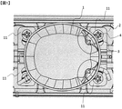
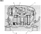
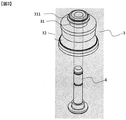
図1は本実施例の圧縮機を底板に取付けた際の上面図、図2は本実施例の圧縮機の縦断面図、図3は本実施例の防振材3と締結具4の分解斜視図、図4は本実施例の防振材3周囲の拡大断面図である。
圧縮機は、例えば冷蔵庫の機械室の底板2上に設置され、底板2近くで概ね底板2と平行に延在する有孔で面状の被取付部11を有する密閉容器1、被取付部11に設けられた防振材3、防振材3の被取付部11からの脱離を抑制する締結具4を有している。密閉容器1内には、振動源としてのモータ、モータの駆動に従って往復動する振動源としてのピストン5、ピストン5が摺動するシリンダ6を有している。防振材3と締結具4とは、本実施例では4つ配されている。なお、図2では締結具4を図示していない。
FIG. 1 is a top view of the compressor of this embodiment mounted on a bottom plate, FIG. 2 is a vertical cross-sectional view of the compressor of this embodiment, and FIG. 3 is an exploded view of the
The compressor is installed on, for example, a
防振材3は、例えばゴム等の弾性部材で形成されて圧縮機の重量を支持する部材である。防振材3は、密閉容器1側に配された、締結具4の外径R1に等しい又はやや小さい内径R1’の空隙である狭空隙31と、底板2側に配された、締結具4の外径よりも大きい内径R2の空隙である広空隙32と、を囲む中空筒状部材である。「やや小さい」とは、締結具4が狭空隙31に挿通された場合に防振材3の狭空隙31を囲む部分が締結具4によって押されて弾性変形するものの破損せずに締結具4の挿通が可能であることをいうことができる。
The
狭空隙31を囲む部分と広空隙32を囲む部分との間には、長さ(R2−R1)に亘って延在して狭空隙31を囲む部分と広空隙32を囲む部分とを接続する接続部33が配されている。防振材3は、狭空隙31を囲む部分、広空隙32を囲む部分、及び接続部33が一体成形されている。
狭空隙31を囲む部分のうち広空隙32を囲む部分から離れた部分には、外径方向に出っ張った凸部311が設けられている。
Between the portion surrounding the
A
まず圧縮機は、被取付部11が防振材3の広空隙32を囲む部分上に載置されることで、底板2との間に防振材3を挟んで設置される。そして、被取付部11の孔内に、狭空隙31を囲む部分が配され、被取付部11の孔上側に凸部311が位置し、かつ孔下側に接続部33が位置することで、被取付部11が上下に変位することを抑制できる。これにより、圧縮機の運転に伴う振動(密閉容器1、すなわち被取付部11が振動する。)や輸送時の振動によって被取付部11が防振材3から脱離することを抑制できる。なお、被取付部11の孔は狭空隙31外径寸法R3に略等しい径である。
First, the compressor is installed with the vibration-damping
本実施例では、防振材3内の空隙に締結具4を挿通することでさらに両部材の脱離を抑制している。狭空隙31に締結具4が挿通すると、狭空隙31を囲む部分は好ましくは締結具4によって外径側に膨らんで弾性変形し、被取付部11と締結具4との間に支持される。これにより締結具4と狭空隙31との密着性が向上し、強固な取付にするとともに、防振材3と締結具4との間に隙間が生じることを抑制できる。すなわち、被取付部11の振動が防振材3を振動させたとき、防振材3と締結具4との間に隙間が生じていると両者が接触して騒音が発生してしまうが、本実施例に依ればこれを抑制できる。
In this embodiment, the
防振材3のうち、広空隙32を囲む部分は、締結具4より大径の空隙、好ましくは締結具4の直径の1.1倍以上、1.5倍以上、又は2.0倍以上である。これにより、締結具4との接触の虞を低減させることができる。すなわち、被取付部11近傍である狭空隙31を囲む部分によって、防振材3と締結具4との固定を行い、その他の領域では接触そのものをしにくい構成とすることで騒音の発生の虞を低減している。
A portion of the
締結具4は、例えば金属で形成されることができ、底板2及び防振材3の孔に挿通されるボルト等にすることができる。挿通後、フランジ41を配して底板2とフランジ41との間に防振材3が位置するようにすることで、防振材3が締結具4から脱離する虞を低減させることができる。
The
本実施例の圧縮機は、冷蔵庫等の各種冷凍機器、機器に設けることができる。 The compressor of this embodiment can be provided in various refrigerating machines such as refrigerators.
1 圧縮機
2 底板
3 防振材
4 締結具
5 ピストン(振動源)
6 シリンダ
1
6 cylinders
Claims (6)
該被取付部に取付けられた弾性を有する防振材と、
締結具と、を備え、
前記防振材は、前記締結具の外径に等しい又はやや小さい径の狭空隙を有する圧縮機。 A closed container including a vibration source inside and an annular attached portion,
An elastic vibration-proof material attached to the attached portion;
And a fastener,
The said vibration isolator is a compressor which has a narrow space|gap whose diameter is equal to or slightly smaller than the outer diameter of the said fastener.
前記締結具が前記狭空隙に挿通されると、前記防振材のうち前記狭空隙を囲む部分が外径側に弾性変形する請求項1に記載の圧縮機。 The narrow gap is a diameter slightly smaller than the outer diameter of the fastener,
The compressor according to claim 1, wherein when the fastener is inserted into the narrow space, a portion of the vibration isolator surrounding the narrow space elastically deforms toward an outer diameter side.
前記締結具は、前記底板及び前記防振材に挿通され、
前記防振材は、
前記底板と前記締結具に配されたフランジとに挟まれる位置に設けられ、
前記被取付部を前記締結具の延在方向両側で挟む形状である冷蔵庫。 A refrigerator in which the compressor according to any one of claims 1 to 4 is installed on a bottom plate of a machine room,
The fastener is inserted through the bottom plate and the vibration isolator,
The vibration damping material is
Provided at a position sandwiched between the bottom plate and the flange arranged on the fastener,
A refrigerator having a shape in which the attached portion is sandwiched on both sides in the extending direction of the fastener.
Priority Applications (1)
| Application Number | Priority Date | Filing Date | Title |
|---|---|---|---|
| JP2019014997A JP2020122437A (en) | 2019-01-31 | 2019-01-31 | Compressor, and device and refrigerator having the same |
Applications Claiming Priority (1)
| Application Number | Priority Date | Filing Date | Title |
|---|---|---|---|
| JP2019014997A JP2020122437A (en) | 2019-01-31 | 2019-01-31 | Compressor, and device and refrigerator having the same |
Publications (1)
| Publication Number | Publication Date |
|---|---|
| JP2020122437A true JP2020122437A (en) | 2020-08-13 |
Family
ID=71993476
Family Applications (1)
| Application Number | Title | Priority Date | Filing Date |
|---|---|---|---|
| JP2019014997A Pending JP2020122437A (en) | 2019-01-31 | 2019-01-31 | Compressor, and device and refrigerator having the same |
Country Status (1)
| Country | Link |
|---|---|
| JP (1) | JP2020122437A (en) |
Cited By (1)
| Publication number | Priority date | Publication date | Assignee | Title |
|---|---|---|---|---|
| WO2023071321A1 (en) * | 2021-10-29 | 2023-05-04 | 广东美的制冷设备有限公司 | Damping assembly and vibration device provided with same |
Citations (4)
| Publication number | Priority date | Publication date | Assignee | Title |
|---|---|---|---|---|
| JPS61116143A (en) * | 1984-11-12 | 1986-06-03 | Toshiba Corp | Supporting device for compressor |
| JPH0381582A (en) * | 1989-08-24 | 1991-04-05 | Mitsubishi Electric Corp | Vibration-proof device for compressor |
| JP2002031056A (en) * | 2000-07-19 | 2002-01-31 | Fujitsu General Ltd | Compressor support device |
| JP2018135773A (en) * | 2017-02-21 | 2018-08-30 | 東芝ライフスタイル株式会社 | refrigerator |
-
2019
- 2019-01-31 JP JP2019014997A patent/JP2020122437A/en active Pending
Patent Citations (4)
| Publication number | Priority date | Publication date | Assignee | Title |
|---|---|---|---|---|
| JPS61116143A (en) * | 1984-11-12 | 1986-06-03 | Toshiba Corp | Supporting device for compressor |
| JPH0381582A (en) * | 1989-08-24 | 1991-04-05 | Mitsubishi Electric Corp | Vibration-proof device for compressor |
| JP2002031056A (en) * | 2000-07-19 | 2002-01-31 | Fujitsu General Ltd | Compressor support device |
| JP2018135773A (en) * | 2017-02-21 | 2018-08-30 | 東芝ライフスタイル株式会社 | refrigerator |
Cited By (1)
| Publication number | Priority date | Publication date | Assignee | Title |
|---|---|---|---|---|
| WO2023071321A1 (en) * | 2021-10-29 | 2023-05-04 | 广东美的制冷设备有限公司 | Damping assembly and vibration device provided with same |
Similar Documents
| Publication | Publication Date | Title |
|---|---|---|
| JP6677948B2 (en) | Hermetic compressor and refrigeration equipment | |
| JP6143314B1 (en) | Hermetic refrigerant compressor and refrigeration system | |
| US6422833B1 (en) | Resonance reducing device for a hermetic compressor | |
| KR20070069773A (en) | Compressor shaking device | |
| JP2015135093A (en) | Electric compressor and method for manufacturing electric compressor | |
| EP2129912B1 (en) | Mount for compressor shell | |
| JP2020122437A (en) | Compressor, and device and refrigerator having the same | |
| US6382932B2 (en) | Hermetic compressor | |
| JP2017044282A (en) | Support device of compressor | |
| EP4202222B1 (en) | A compressor comprising a vibration damping member | |
| KR101897852B1 (en) | Reciprocating compressor | |
| KR20030049536A (en) | Vibration damping apparatus for compressor | |
| CN206637752U (en) | Outdoor unit of air conditioner | |
| KR20160055529A (en) | Reciprocating compressor and refrigerator including the same | |
| CN100529396C (en) | Refrigerant compressor housing | |
| JP2016109399A (en) | Heat source unit of freezer | |
| JP4774837B2 (en) | Refrigerant compressor | |
| CN206771807U (en) | Compressor and there is its refrigeration plant | |
| US10961996B2 (en) | Closed compressor and refrigeration device | |
| KR20130071030A (en) | Refrigerator having vibration proof device for compressor | |
| KR100621042B1 (en) | Compressor Support of Refrigerator | |
| JP2001133079A (en) | Refrigerating device | |
| JP2018062930A (en) | Electric compressor | |
| KR100622256B1 (en) | Motor Stator Support of Compressor | |
| CN109798237A (en) | refrigerator |
Legal Events
| Date | Code | Title | Description |
|---|---|---|---|
| A521 | Request for written amendment filed |
Free format text: JAPANESE INTERMEDIATE CODE: A523 Effective date: 20190201 |
|
| A621 | Written request for application examination |
Free format text: JAPANESE INTERMEDIATE CODE: A621 Effective date: 20210205 |
|
| RD02 | Notification of acceptance of power of attorney |
Free format text: JAPANESE INTERMEDIATE CODE: A7422 Effective date: 20210308 |
|
| RD04 | Notification of resignation of power of attorney |
Free format text: JAPANESE INTERMEDIATE CODE: A7424 Effective date: 20210323 |
|
| A521 | Request for written amendment filed |
Free format text: JAPANESE INTERMEDIATE CODE: A523 Effective date: 20210210 |
|
| A131 | Notification of reasons for refusal |
Free format text: JAPANESE INTERMEDIATE CODE: A131 Effective date: 20210928 |
|
| A02 | Decision of refusal |
Free format text: JAPANESE INTERMEDIATE CODE: A02 Effective date: 20220322 |