JP2020171936A - Rolling system operator support device and cold tandem rolling system comprising same - Google Patents
Rolling system operator support device and cold tandem rolling system comprising same Download PDFInfo
- Publication number
- JP2020171936A JP2020171936A JP2019074645A JP2019074645A JP2020171936A JP 2020171936 A JP2020171936 A JP 2020171936A JP 2019074645 A JP2019074645 A JP 2019074645A JP 2019074645 A JP2019074645 A JP 2019074645A JP 2020171936 A JP2020171936 A JP 2020171936A
- Authority
- JP
- Japan
- Prior art keywords
- center
- rolled material
- measuring device
- amount
- centering device
- Prior art date
- Legal status (The legal status is an assumption and is not a legal conclusion. Google has not performed a legal analysis and makes no representation as to the accuracy of the status listed.)
- Granted
Links
- 238000005096 rolling process Methods 0.000 title claims abstract description 107
- 239000000463 material Substances 0.000 claims abstract description 104
- 238000011144 upstream manufacturing Methods 0.000 claims abstract description 22
- 238000012545 processing Methods 0.000 description 28
- 238000000034 method Methods 0.000 description 8
- 238000010586 diagram Methods 0.000 description 4
- 230000006870 function Effects 0.000 description 3
- 230000007246 mechanism Effects 0.000 description 3
- 230000008569 process Effects 0.000 description 3
- 230000009118 appropriate response Effects 0.000 description 2
- 238000012937 correction Methods 0.000 description 2
- 238000013024 troubleshooting Methods 0.000 description 2
- 241000699670 Mus sp. Species 0.000 description 1
- 230000009471 action Effects 0.000 description 1
- 238000005097 cold rolling Methods 0.000 description 1
- 238000004891 communication Methods 0.000 description 1
- 230000007423 decrease Effects 0.000 description 1
- 238000001514 detection method Methods 0.000 description 1
- 230000000694 effects Effects 0.000 description 1
- 230000005489 elastic deformation Effects 0.000 description 1
- 238000005401 electroluminescence Methods 0.000 description 1
- 239000004973 liquid crystal related substance Substances 0.000 description 1
- 238000012544 monitoring process Methods 0.000 description 1
- 230000002035 prolonged effect Effects 0.000 description 1
Images
Landscapes
- Control Of Metal Rolling (AREA)
Abstract
Description
本発明は、圧延システムのオペレータ支援装置および該装置を備える冷間タンデム圧延システムに関する。 The present invention relates to an operator assisting device for a rolling system and a cold tandem rolling system including the device.
冷間タンデム圧延において、圧延材(ストリップ)の蛇行を修正する技術として、例えば、特許文献1は、タンデム式冷間圧延機の第1スタンド入口におけるストリップの蛇行修正方法において、第1スタンドとその上流の蛇行修正装置間の距離L(m)と、第1スタンドと蛇行修正装置間に付与されるストリップ張力σ(kgf/mm2)を、σ×L≧20を満足するよう配置することを特徴とするストリップの蛇行修正方法を開示する。
As a technique for correcting meandering of a rolled material (strip) in cold tandem rolling, for example,
圧延材にキャンバ(横曲がり)が存在した状態で圧延されたり、圧延材が幅方向にずれたまま溶接され、くの字型になった状態で圧延されたりすると、圧延材が蛇行するので、オフセンタを修正する必要がある。圧延材のオフセンタは、センタリング装置によって修正される。圧延材の蛇行の大小は、圧延材のオフセンタ量の大小と相関しているので、圧延材の蛇行の程度は、圧延材のオフセンタ量で判断できる。しかし、圧延材のオフセンタが修正されても、オフセンタ量が大きかった箇所が原因で圧延蛇行トラブル(例えば、圧延材が引きちぎれる)が発生する場合があることが分かった。以後、圧延母材(圧延前の圧延材)のオフセンタを“オフセンタ”と記載し、圧延後の圧延材のオフセンタおよび幅方向に非対象な状況を“蛇行”と記載する。 If the rolled material is rolled with a camber (horizontal bend), or if the rolled material is welded with a deviation in the width direction and rolled in a dogleg shape, the rolled material meanders. Off-center needs to be modified. The off-center of the rolled material is corrected by the centering device. Since the magnitude of the meandering of the rolled material correlates with the magnitude of the off-center amount of the rolled material, the degree of meandering of the rolled material can be determined by the off-center amount of the rolled material. However, it has been found that even if the off-center of the rolled material is corrected, a rolling meandering trouble (for example, the rolled material is torn off) may occur due to a portion where the amount of off-center is large. Hereinafter, the off-center of the rolled base material (rolled material before rolling) will be referred to as "off-center", and the off-center of the rolled material after rolling and the non-symmetrical situation in the width direction will be described as "meandering".
本発明の目的は、オフセンタ量が大きかった箇所が原因で発生する圧延トラブルを事前に回避することができる、圧延システムのオペレータ支援装置および該装置を備える冷間タンデム圧延システムを提供することである。 An object of the present invention is to provide an operator assisting device for a rolling system and a cold tandem rolling system including the device, which can avoid rolling troubles caused by a portion having a large off-center amount in advance. ..
本発明の第1局面に係る圧延システムのオペレータ支援装置は、張力を付与されながら送られてくる圧延材を冷間圧延する冷間タンデム圧延機と、前記冷間タンデム圧延機の上流に配置され、前記圧延材の蛇行を防止するために前記圧延材のオフセンタを修正する第1のセンタリング装置と、前記第1のセンタリング装置の下流に配置され、前記第1のセンタリング装置でオフセンタが修正された前記圧延材のオフセンタ量を測定する第1のオフセンタ測定装置と、前記第1のセンタリング装置の上流に配置され、前記圧延材の蛇行を防止するために前記圧延材のオフセンタを修正する第2のセンタリング装置と、前記第2のセンタリング装置の下流に配置され、前記第2のセンタリング装置でオフセンタが修正された前記圧延材のオフセンタ量を測定する第2のオフセンタ測定装置と、を備える圧延システムのオペレータ支援装置であって、前記第1のオフセンタ測定装置が配置されている第1の箇所よりも前記圧延材に付与されている張力が小さくなっており、かつ、前記第1のセンタリング装置よりも上流にあり、かつ、前記第2のオフセンタ測定装置よりも下流にある第2の箇所に配置され、前記圧延材のオフセンタ量を測定する第3のオフセンタ測定装置と、前記第3のオフセンタ測定装置が測定したオフセンタ量を可視化したデータをリアルタイムで出力する出力部と、を備える。 The operator support device for the rolling system according to the first aspect of the present invention is arranged in a cold tandem rolling mill that cold-rolls the rolled material sent while applying tension, and upstream of the cold tandem rolling mill. A first centering device that corrects the off-center of the rolled material in order to prevent the rolling material from meandering, and a first centering device that is arranged downstream of the first centering device, and the off-center is corrected by the first centering device. A first off-center measuring device for measuring the off-center amount of the rolled material and a second off-center measuring device for the rolled material, which is arranged upstream of the first centering device and modifies the off-center of the rolled material in order to prevent meandering of the rolled material. A rolling system including a centering device and a second off-center measuring device which is arranged downstream of the second centering device and measures the amount of off-center of the rolled material whose off-center has been corrected by the second centering device. In the operator assist device, the tension applied to the rolled material is smaller than that of the first location where the first off-center measuring device is arranged, and the tension applied to the rolled material is smaller than that of the first centering device. A third off-center measuring device and a third off-center measuring device, which are located upstream and downstream of the second off-center measuring device and measure the amount of off-center of the rolled material. It is provided with an output unit that outputs data that visualizes the amount of off-center measured by.
本発明者らは、以下の知見に基づいて、本発明を創作した。圧延材のうち、オフセンタ量が大きかった部分の中には、圧延材の弾性変形によりオフセンタ量が強制的に小さくされている部分(以下、弾性変形部分)があり、弾性変形部分が圧延されたときに、圧延トラブルが発生する可能性があることが分かった。 The present inventors created the present invention based on the following findings. Among the parts of the rolled material where the off-center amount was large, there was a part where the off-center amount was forcibly reduced by the elastic deformation of the rolled material (hereinafter referred to as the elastically deformed part), and the elastically deformed part was rolled. It turns out that sometimes rolling troubles can occur.
弾性変形部分は、オフセンタの修正により、オフセンタ量が小さくされているが(オフセンタの潜在化)、弾性変形部分は、変形を元に戻したとき、オフセンタ量が大きくなる(オフセンタの顕在化)。センタリング装置から離れ、かつ、圧延材に作用する張力が小さいと、弾性変形部分は、変形が元に戻り、オフセンタ量が大きくなる。 The amount of off-center is reduced in the elastically deformed portion by modifying the off-center (latent off-center), but the amount of off-center is increased in the elastically deformed portion when the deformation is restored (actualization of off-center). When the tension acting on the rolled material is small and the distance from the centering device is small, the elastically deformed portion returns to its original deformation and the off-center amount becomes large.
従って、センタリング装置によってオフセンタが修正された圧延材が、冷間タンデム圧延機に到達する前に、センタリング装置から離れており、かつ、圧延材に付加されている張力が小さい箇所で圧延材のオフセンタ量を測定すればよいことになる。その箇所では、弾性変形部分のオフセンタが顕在化(オフセンタが可視化)しているので、オペレータは、弾性変形部分が冷間タンデム圧延機に到達する前に弾性変形部分を発見できる。 Therefore, the rolled material whose off-center has been corrected by the centering device is separated from the centering device and the tension applied to the rolled material is small before reaching the cold tandem rolling mill. All you have to do is measure the amount. At that location, the off-center of the elastically deformed portion is actualized (the off-center is visualized), so that the operator can find the elastically deformed portion before the elastically deformed portion reaches the cold tandem rolling mill.
本発明の第1局面に係る圧延システムのオペレータ支援装置では、第2の箇所をオフセンタが顕在化する箇所とし、第2の箇所に第3のオフセンタ測定装置を配置し、圧延材のオフセンタ量を測定する。出力部は、第3のオフセンタ測定装置が測定したオフセンタ量を可視化したデータをリアルタイムで出力する。オペレータは、このデータを見ることにより、弾性変形部分が冷間タンデム圧延機に到達する前に、弾性変形部分を発見することができるので、圧延トラブル防止のための対策をとることができる。 In the operator support device of the rolling system according to the first aspect of the present invention, the second point is a place where the off-center becomes apparent, and the third off-center measuring device is arranged at the second place to measure the amount of off-center of the rolled material. Measure. The output unit outputs data that visualizes the amount of off-center measured by the third off-center measuring device in real time. By looking at this data, the operator can find the elastically deformed portion before it reaches the cold tandem rolling mill, and can take measures to prevent rolling troubles.
以上により、本発明の第1局面に係る圧延システムのオペレータ支援装置によれば、オフセンタ量が大きかった箇所が原因で発生する圧延トラブルを事前に回避することができる。 As described above, according to the operator assist device of the rolling system according to the first aspect of the present invention, it is possible to avoid rolling troubles caused by a portion having a large off-center amount in advance.
上記構成において、前記第2の箇所は、前記冷間タンデム圧延機の1番目の圧延スタンドより25m以上上流にあり、かつ、前記第2のセンタリング装置より25m以上下流において、前記圧延材に付与されている張力が3.0kgf/mm2以下となる箇所である。 In the above configuration, the second portion is applied to the rolled material 25 m or more upstream from the first rolling stand of the cold tandem rolling mill and 25 m or more downstream from the second centering device. This is a place where the tension is 3.0 kgf / mm 2 or less.
この構成は、第2の箇所の具体例である。これは、本発明者らの圧延システムを基にして決めている。第2の箇所は、第1条件と第2条件とを満足する。第1条件は、冷間タンデム圧延機の1番目の圧延スタンドより25m以上上流に第2の箇所がある。これにより、オペレータが弾性変形部分の存在を知ったとき、この部分が1番目の圧延スタンドに到達する前に、適切な対応をとるために必要な時間を確保することができる。 This configuration is a specific example of the second part. This is determined based on the rolling system of the present inventors. The second part satisfies the first condition and the second condition. The first condition is that there is a second portion 25 m or more upstream from the first rolling stand of the cold tandem rolling mill. As a result, when the operator becomes aware of the existence of the elastically deformed portion, it is possible to secure the time required to take an appropriate response before this portion reaches the first rolling stand.
第2条件は、第2のセンタリング装置より25m以上下流であり、圧延材に付与されている張力が3.0kgf/mm2以下となる箇所である。潜在化しているオフセンタが顕在化するためには、センタリング装置から十分に離れており、かつ、圧延材に付与されている張力が小さくなければならないからである。 The second condition is a location 25 m or more downstream from the second centering device and the tension applied to the rolled material is 3.0 kgf / mm 2 or less. This is because, in order for the latent off-center to become apparent, it must be sufficiently separated from the centering device and the tension applied to the rolled material must be small.
上記構成において、前記第3のオフセンタ測定装置が測定したオフセンタ量の絶対値が、所定の第1のしきい値を超えたとき、報知する第1の報知部をさらに備える。 In the above configuration, a first notification unit for notifying when the absolute value of the off-center amount measured by the third off-center measuring device exceeds a predetermined first threshold value is further provided.
この報知により、オペレータは、圧延材の弾性変形箇所が原因で発生する圧延トラブルを事前に回避するための処置をすることができる。 With this notification, the operator can take measures in advance to avoid rolling troubles caused by elastically deformed portions of the rolled material.
上記構成において、前記第3のオフセンタ測定装置が測定したオフセンタ量を示すグラフの傾きの絶対値が、所定の第2のしきい値を超えたとき、報知する第2の報知部をさらに備える。 In the above configuration, a second notification unit for notifying when the absolute value of the slope of the graph showing the off-center amount measured by the third off-center measuring device exceeds a predetermined second threshold value is further provided.
この報知により、オペレータは、圧延材の弾性変形箇所が原因で発生する圧延トラブルを事前に回避するための処置をすることができる。 With this notification, the operator can take measures in advance to avoid rolling troubles caused by elastically deformed portions of the rolled material.
本発明の第2局面に係る冷間タンデム圧延システムは、張力を付与されながら送られてくる圧延材を冷間圧延する冷間タンデム圧延機と、前記冷間タンデム圧延機の上流に配置され、前記圧延材の蛇行を防止するために前記圧延材のオフセンタを修正する第1のセンタリング装置と、前記第1のセンタリング装置の下流に配置され、前記第1のセンタリング装置でオフセンタが修正された前記圧延材のオフセンタ量を測定する第1のオフセンタ測定装置と、前記第1のセンタリング装置の上流に配置され、前記圧延材の蛇行を防止するために前記圧延材のオフセンタを修正する第2のセンタリング装置と、前記第2のセンタリング装置の下流に配置され、前記第2のセンタリング装置でオフセンタが修正された前記圧延材のオフセンタ量を測定する第2のオフセンタ測定装置と、オペレータ支援装置と、を備え、前記オペレータ支援装置は、前記第1のオフセンタ測定装置が配置されている第1の箇所よりも前記圧延材に付与されている張力が小さくなっており、かつ、前記第1のセンタリング装置よりも上流にあり、かつ、前記第2のオフセンタ測定装置よりも下流にある第2の箇所に配置され、前記圧延材のオフセンタ量を測定する第3のオフセンタ測定装置と、前記第3のオフセンタ測定装置が測定したオフセンタ量を可視化したデータをリアルタイムで出力する出力部と、を備える。 The cold tandem rolling system according to the second aspect of the present invention is arranged in a cold tandem rolling mill that cold-rolls the rolled material sent while applying tension, and upstream of the cold tandem rolling mill. A first centering device that corrects the off-center of the rolled material in order to prevent meandering of the rolled material, and a first centering device that is arranged downstream of the first centering device and whose off-center is corrected by the first centering device. A first off-center measuring device for measuring the off-center amount of the rolled material and a second centering which is arranged upstream of the first centering device and corrects the off-center of the rolled material in order to prevent the rolled material from meandering. An apparatus, a second off-center measuring apparatus arranged downstream of the second centering apparatus, a second off-center measuring apparatus for measuring the off-center amount of the rolled material whose off-center has been corrected by the second centering apparatus, and an operator assisting apparatus. In addition, the operator assisting device has a smaller tension applied to the rolled material than the first location where the first off-center measuring device is arranged, and the tension applied to the rolled material is smaller than that of the first centering device. A third off-center measuring device for measuring the amount of off-center of the rolled material, and a third off-center measuring device, which are located upstream and downstream of the second off-center measuring device. It includes an output unit that outputs data that visualizes the amount of off-center measured by the apparatus in real time.
本発明の第2局面に係る冷間タンデム圧延システムは、本発明の第1局面に係る圧延システムのオペレータ支援装置を冷間タンデム圧延システムの観点から規定しており、本発明の第1局面に係る圧延システムのオペレータ支援装置と同様の作用効果を有する。 The cold tandem rolling system according to the second aspect of the present invention defines the operator support device of the rolling system according to the first aspect of the present invention from the viewpoint of the cold tandem rolling system, and the first aspect of the present invention It has the same effect as the operator assist device of the rolling system.
本発明によれば、オフセンタ量が大きかった箇所が原因で発生する圧延トラブルを事前に回避することができる。 According to the present invention, it is possible to avoid rolling troubles caused by a portion having a large amount of off-center in advance.
以下、図面に基づいて本発明の実施形態を詳細に説明する。各図において、同一符号を付した構成は、同一の構成であることを示し、その構成について、既に説明している内容については、その説明を省略する。本明細書において、総称する場合にはハイフンを省略した参照符号で示し(例えば、グラフG)、個別の構成を指す場合にはハイフンを付した参照符号で示す(例えば、グラフG−1)。 Hereinafter, embodiments of the present invention will be described in detail with reference to the drawings. In each figure, the configurations with the same reference numerals indicate that they are the same configuration, and the description of the configurations already described will be omitted. In the present specification, when they are generically referred to, they are indicated by reference numerals without hyphens (for example, graph G), and when they refer to individual configurations, they are indicated by reference numerals with hyphens (for example, graph G-1).
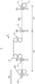
図1は、実施形態に係る圧延システム1の一部を示す模式図である。圧延システム1は、冷間タンデム圧延システムの一例であり、圧延対象である圧延材WKを自動的に所定の目標の厚み(板厚)となるように冷間圧延するシステムである。圧延システム1は、センタリング装置10と、オフセンタ測定装置11と、オフセンタ測定装置12と、ブライドルロール13と、センタリング装置14と、オフセンタ測定装置15と、圧延機16と、を備える。
FIG. 1 is a schematic view showing a part of the
圧延材WKは、張力を付与されながら矢印A方向に送られる。圧延システム1の上流から順に、センタリング装置10、オフセンタ測定装置11、オフセンタ測定装置12、ブライドルロール13、センタリング装置14、オフセンタ測定装置15、圧延機16が配置されている。
The rolled material WK is fed in the direction of arrow A while being tensioned. The centering
センタリング装置10は、第2のセンタリング装置の一例であり、この装置の上流から張力を付与されながら送られてくる圧延材WKに対して、オフセンタ測定装置11で計測した圧延材WKのオフセンタ量を基にオフセンタが小さくなるように、センタリング装置10の幅方向の傾きを調整しながら圧延材WKのオフセンタを修正する。センタリング装置10の上流には、図示はされていないが、圧延材WKに張力を付与する装置(例えば、ブライドルロール)が配置されている。
The centering
オフセンタ測定装置11は、第2のオフセンタ測定装置の一例であり、センタリング装置10の下流に配置され、センタリング装置10でオフセンタが修正された直後の圧延材WKのオフセンタ量V1を測定する。詳しく説明する。オフセンタ測定装置11は、圧延材WKの下方から光を出射する光源部と、圧延材WKの上方に配置され、光源部が出射した光を用いて、圧延材WKの左右側面の位置を検知する検知部(例えばリニアセンサ)と、を備え、検知した左右側面の位置に基づいて、オフセンタ量V1を計測する。
The off-
オフセンタ測定装置12は、第3のオフセンタ測定装置の一例であり、オフセンタ測定装置11が配置されている箇所P1より下流の箇所P2(第2の箇所)に配置されている。オフセンタ測定装置12は、箇所P2で圧延材WKのオフセンタ量V2を測定する。オフセンタ測定装置12がオフセンタ量を測定する仕組みは、オフセンタ測定装置11と同じである。
The off-
箇所P2は、圧延材WKに付与されている張力が箇所P1と同じ(ほぼ同じ)であるが、オフセンタ測定装置15が配置されている箇所P3(第1の箇所)よりも圧延材WKに付与されている張力は小さい。箇所P2は、センタリング装置10から十分に離れており、かつ、圧延材WKに付与されている張力が小さい箇所でなければならない。
At the location P2, the tension applied to the rolled material WK is the same (almost the same) as the location P1, but the tension applied to the rolled material WK is higher than that at the location P3 (first location) where the off-
オフセンタ測定装置12とセンタリング装置10との距離D1は、例えば、約45mである。オフセンタ測定装置12と圧延機16との距離D2は、例えば、約85mである。箇所P2(第2の箇所)において、圧延材WKに付与されている張力は、例えば、3.0kgf/mm2以下である。これらについての理由は、後で説明する。
The distance D1 between the off-
オフセンタ測定装置12の下流には、ブライドルロール13が配置されている。センタリング装置10から下流に向かうに従って、圧延材WKに付与されている張力が小さくなるので、ブライドルロール13によって、圧延材WKに張力が付与される。
A bridle roll 13 is arranged downstream of the off-
ブライドルロール13の下流には、センタリング装置14が配置されている。センタリング装置14は、第1のセンタリング装置の一例であり、この装置の上流から張力を付与されながら送られてくる圧延材WKのオフセンタを修正する。センタリング装置14がオフセンタを修正する仕組みは、センタリング装置10と同じである。
A centering device 14 is arranged downstream of the bridle roll 13. The centering device 14 is an example of the first centering device, and corrects the off-center of the rolled material WK sent from the upstream of this device while being tensioned. The mechanism by which the centering device 14 corrects the off-center is the same as that of the centering
オフセンタ測定装置15は、第1のオフセンタ測定装置の一例であり、センタリング装置14の下流に配置され、センタリング装置14でオフセンタが修正された直後の圧延材WKのオフセンタ量V3を測定する。オフセンタ測定装置15がオフセンタ量を測定する仕組みは、オフセンタ測定装置11と同じである。
The off-
オフセンタ測定装置15の下流には、圧延機16が配置されている。圧延材WKは、センタリング装置14でオフセンタが修正されて、圧延機16に送られる。圧延機16は、冷間タンデム圧延機の一例であり、複数(例えば5つ)の圧延スタンドを配置することで、圧延材WKを連続的に圧延する。図1では、複数の圧延スタンドのうち、圧延材WKを最初に圧延する圧延スタンド161(No.1スタンド)が示されている。
A rolling
出側張力差測定装置162は、圧延スタンド161の下流に配置されており、圧延スタンド161で圧延された直後の圧延材WKの出側張力差V4を測定する。詳しく説明する。出側張力差測定装置162は、圧延材WKのうち、ワークサイドの側の部分の張力を測定する第1の張力測定器と、ドライブサイド側の部分の張力を測定する第2の張力測定器と、を備え、第1の張力測定器で測定された張力と第2の張力測定器で測定された張力の差とが、出側張力差V4となる。後で説明するように、圧延材WKのオフセンタが潜在化した弾性変形部分が圧延されると、出側張力差V4が大きくなる。これは、圧延材WKにスラスト力(幅方向の力)が作用していることを示す。
The output side tension
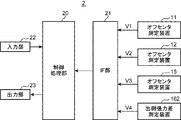
図2は、実施形態に係るオペレータ支援装置2のブロック図である。オペレータ支援装置2は、圧延システム1のオペレータを支援する。オペレータ支援装置2は、制御処理部20と、IF部21と、オフセンタ測定装置11,12,15と、出側張力差測定装置162と、入力部22と、出力部23と、を備える。
FIG. 2 is a block diagram of the
制御処理部20は、オペレータ支援装置2の全体を統括し、オペレータ支援装置2の動作に必要な制御および処理をする。制御処理部20は、CPU(Central Processing Unit)、RAM(Random Access Memory)、ROM(Read Only Memory)、および、HDD(Hard Disk Drive)等のハードウェア、制御処理を実行するためのプログラムおよびデータ等によって実現される。
The
IF部21は、制御処理部20に接続され、制御処理部20の制御に従って、例えば、外部の機器との間でデータを入出力する回路である。詳しく説明する。IF部21は、オフセンタ測定装置11が測定したオフセンタ量V1、オフセンタ測定装置12が測定したオフセンタ量V2、オフセンタ測定装置15が測定したオフセンタ量V3、出側張力差測定装置162が測定した出側張力差V4が、それぞれ、リアルタイムに入力し、これらを制御処理部20へ送る。
The
IF部21は、例えば、シリアル通信方式であるRS−232Cのインターフェース回路、Bluetooth(登録商標)規格を用いたインターフェース回路、USB(Universal Serial Bus)規格を用いたインターフェース回路等である。
The
入力部22は、制御処理部20に接続され、オペレータが、各種の情報、データ、命令等を入力するための装置である。入力部22は、所定の機能を割り付けられた複数の入力スイッチ、キーボード、マウス、タッチパネル等によって実現される。
The
出力部23は、制御処理部20に接続され、制御処理部20の制御に従って、入力部22から入力されたコマンド、データ、オフセンタ量V1,V2,V3、出側張力差V4を出力する装置である。出力部23は、表示装置、プリンタ等によって実現される。表示装置は、例えば、液晶ディスプレイ、有機ELディスプレイ(organic electroluminescence display)である。
The
出力部23は、オフセンタ測定装置11が測定したオフセンタ量V1、オフセンタ測定装置12が測定したオフセンタ量V2、オフセンタ測定装置15が測定したオフセンタ量V3、出側張力差測定装置162が測定した出側張力差V4を示すグラフGをリアルタイムで出力する。グラフGは、これらの量を可視化したデータの例である。グラフGについて、詳しく説明する。
The
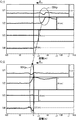
図3は、グラフGの2つの例(グラフG−1,G−2)を示す図である。グラフG−1は、ある時刻t1でのグラフGである。グラフG−2は、時刻t1より遅いある時刻t2でのグラフGである。グラフGは、4段のグラフにより構成される。1段目のグラフは、オフセンタ測定装置11が測定したオフセンタ量V1を示す。2段目のグラフは、オフセンタ測定装置12が測定したオフセンタ量V2を示す。3段目のグラフは、オフセンタ測定装置15が測定したオフセンタ量V3を示す。4段目のグラフは、出側張力差測定装置162が測定した出側張力差V4を示す。
FIG. 3 is a diagram showing two examples of graph G (graphs G-1 and G-2). Graph G-1 is a graph G at a certain time t1. Graph G-2 is a graph G at a certain time t2, which is later than the time t1. The graph G is composed of a four-stage graph. The graph in the first row shows the off-center amount V1 measured by the off-
グラフGの縦軸は、それぞれ、オフセンタ量V1、オフセンタ量V2、オフセンタ量V3、出側張力差V4を示す。 The vertical axis of the graph G shows the off-center amount V1, the off-center amount V2, the off-center amount V3, and the output tension difference V4, respectively.
グラフGの横軸は、圧延スタンド161を基準(0m)にした距離を示す。マイナスの距離は、圧延スタンド161より上流を示す。プラスの距離は、圧延スタンド161より下流を示す。オフセンタ測定装置11は、圧延スタンド161から距離d1の位置にある。オフセンタ測定装置12は、圧延スタンド161から距離d2の位置にある。オフセンタ測定装置15は、圧延スタンド161から距離d3の位置にある。出側張力差測定装置162は、圧延スタンド161の直後の位置にある。
The horizontal axis of the graph G indicates the distance with respect to the rolling
グラフG−1を参照して、楕円は、圧延材WKの弾性変形部分WKpを示す。この部分WKpは、圧延スタンド161から−50mの距離の位置にある。オフセンタ量V1は、センタリング装置10でオフセンタが修正された直後の圧延材WKのオフセンタ量なので、弾性変形部分WKpのオフセンタ量は小さい(オフセンタの潜在化)。
With reference to graph G-1, the ellipse indicates the elastically deformed portion WKp of the rolled material WK. This partial WKp is located at a distance of −50 m from the rolling
これに対して、オフセンタ量V2は、センタリング装置10から離れており、かつ、圧延材WKに付加されている張力が小さい箇所P2で測定される。オフセンタ量V2のグラフにおいて、弾性変形部分WKpの傾きの絶対値が大きくなっている。これは、弾性変形部分WKpの変形が元に戻ったからである(オフセンタの顕在化)。
On the other hand, the off-center amount V2 is measured at a position P2 away from the centering
グラフG2を参照して、圧延材WKは、時刻t1から時刻t2の期間に約50m進んでいる。圧延材WKは、ブライドルロール13で張力が付与され、センタリング装置14でオフセンタが修正される。従って、弾性変形部分WKpはオフセンタ量V3がほぼゼロにされて(オフセンタが潜在化)、圧延スタンド161に送られる。
With reference to the graph G2, the rolled material WK advances about 50 m in the period from time t1 to time t2. Tension is applied to the rolled material WK by the bridle roll 13, and the off-center is corrected by the centering device 14. Therefore, the elastically deformed portion WKp is sent to the rolling
グラフG2において、弾性変形部分WKpは、圧延スタンド161で圧延された直後の位置にある。弾性変形部分WKpの出側張力差V4が大きくなっている。これは、圧延材WKのオフセンタを潜在化した弾性変形部分WKpが圧延されることでスラスト力(幅方向の力)が作用していることを示す。
In the graph G2, the elastically deformed portion WKp is in the position immediately after being rolled by the rolling
弾性変形部分WKpか否かは、オフセンタ量V2の絶対値が大きい部分、または、オフセンタ量V2の絶対値が大きくなくても、オフセンタ量V2を示すグラフの傾きの絶対値が大きい部分である。オペレータは、オフセンタ量V2のグラフを監視することにより、弾性変形部分WKpが圧延される前に、弾性変形部分WKpの存在を知ることができる。これにより、オペレータは、適切な対応が可能となる(例えば、圧延速度を減速したり、レベリング処理をしたり、圧延システム1を停止したりする)。圧延速度を減速するのは、圧延トラブルを最小化するためである。圧延速度が高速のままで圧延トラブルが発生すると、破断した圧延材WKが圧延スタンド161のワークロールと衝突し何重にも手繰れ、その処置が長引くことがある。例えば、圧延速度が高速の場合、トラブル処置に要する時間が8〜12時間であり、圧延速度が低速の場合、トラブル処置時間が10〜15分である。
Whether or not it is the elastically deformed portion WKp is a portion where the absolute value of the off-center amount V2 is large, or a portion where the absolute value of the slope of the graph showing the off-center amount V2 is large even if the absolute value of the off-center amount V2 is not large. By monitoring the graph of the off-center amount V2, the operator can know the existence of the elastically deformed portion WKp before the elastically deformed portion WKp is rolled. This allows the operator to take appropriate action (eg, slow down the rolling speed, perform the leveling process, stop the rolling system 1). The reason for reducing the rolling speed is to minimize rolling troubles. If a rolling trouble occurs while the rolling speed remains high, the broken rolled material WK may collide with the work roll of the rolling
弾性変形部分WKpか否かの判断は、自動ですることもできる。この場合、制御処理部20は、オフセンタ量V2のしきい値Th1(所定の第1のしきい値)、および、オフセンタ量V2を示すグラフの傾きのしきい値Th2(所定の第2のしきい値)を予め記憶しており、オフセンタ量V2の絶対値がしきい値Th1を超えているか否か、オフセンタ量V2を示すグラフの傾きの絶対値がしきい値Th2を超えているか否かを監視する。制御処理部20は、オフセンタ量V2の絶対値がしきい値Th1を超えたとき、または、オフセンタ量V2を示すグラフの傾きの絶対値がしきい値Th2を超えたとき、出力部23に報知させる。これにより、オペレータは、弾性変形部分WKpの存在を知ることができる。
Judgment as to whether or not the elastically deformed portion WKp can be performed automatically. In this case, the
なお、オフセンタ量V1,V3を用いても、オフセンタ量V2と同じ方法で、弾性変形部分WKpか否かの判断をすることができる。 Even if the off-center amounts V1 and V3 are used, it is possible to determine whether or not the elastically deformed portion WKp is present in the same manner as the off-center amount V2.
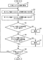
実施形態に係るオペレータ支援装置2の動作を説明する。図4は、これを説明するフローチャートである。図1、図2および図4を参照して、圧延システム1の動作が開始する(S1)。オフセンタ測定装置11はオフセンタ量V1を測定し、オフセンタ測定装置12はオフセンタ量V2を測定し、オフセンタ測定装置15はオフセンタ量V3を測定し、出側張力差測定装置162は出側張力差V4を測定する。
The operation of the
制御処理部20は、IF部21を用いて、測定されたオフセンタ量V1,V2,V3、出側張力差V4を受信する(S2)。制御処理部20は、オフセンタ量V1,V2,V3、出側張力差V4を示すグラフG(例えば、図3に示すグラフG)を生成し、出力部23は、グラフGを出力する(S3)。
The
制御処理部20は、オフセンタ量V2の絶対値がしきい値Th1(第1のしきい値)を超えてるか否かを判定する(S4)。制御処理部20は、オフセンタ量V2の絶対値がしきい値Th1を超えていると判定したとき(S4でYes)、出力部23は、報知する(S5)。これは、オフセンタ量V2の絶対値がしきい値Th1を超えてることをオペレータに示す報知である。
The
制御処理部20は、オフセンタ量V2の絶対値がしきい値Th1以下と判定したとき(S4でNo)、オフセンタ量V2のグラフについて、この傾きの絶対値がしきい値Th2(第2のしきい値)を超えてるか否かを判定する(S6)。制御処理部20は、グラフの傾きの絶対値がしきい値Th2を超えてると判定したとき(S6でYes)、出力部23は、報知する(S7)。これは、オフセンタ量V2を示すグラフの傾きの絶対値がしきい値Th2を超えてることをオペレータに示す報知である。
When the
制御処理部20は、グラフの傾きの絶対値がしきい値Th2以下と判定したとき(S6でNo)、または、処理S5の後、または、処理S7の後、圧延システム1が動作中か否かを判断する(S8)。制御処理部20は、圧延システム1が動作中と判断したとき(S8でYes)、処理S2に戻る。制御処理部20は、圧延システム1の動作が停止していると判断したとき(S8でNo)、オペレータ支援装置2の動作を終了させる。
Whether or not the rolling
処理S5において、出力部23は、第1の報知部の機能を有する。処理S7において、出力部23は、第2の報知部の機能を有する。第1の報知部は、オフセンタ測定装置12が測定したオフセンタ量V2の絶対値が、しきい値Th1(第1しきい値)を超えたとき、報知する。第2の報知部は、オフセンタ測定装置12が測定したオフセンタ量V2を示すグラフの傾きの絶対値が、しきい値Th2(第2しきい値)を超えたとき、報知する。これにより、オペレータは、オフセンタ量が大きかった箇所(弾性変形部分WKp)が原因で発生する圧延トラブルを事前に回避するための処置をすることができる。なお、報知は、画像でもよく、音声でもよい。音声の場合は、出力部23に備えられるスピーカ(不図示)が第1の報知部および第2の報知部となる。
In the process S5, the
図1を参照して、距離D1および距離D2の具体例を説明する。これらは、本発明者らの圧延システムを基にして決めている。潜在化しているオフセンタが顕在化するためには、箇所P2は、センタリング装置10から十分に離れており、かつ、圧延材WKに付与されている張力が小さい箇所でなければならない。距離D1は、この観点から決まる。例えば、距離D1は、25m以上であり、箇所P2で圧延材WKに付加されている張力は、3.0kgf/mm2以下である。
Specific examples of the distance D1 and the distance D2 will be described with reference to FIG. These are determined based on the rolling system of the present inventors. In order for the latent off-center to become apparent, the portion P2 must be sufficiently distant from the centering
距離D2は、オペレータが弾性変形部分WKpの存在を知ったとき、この部分が圧延スタンド161に到達する前に、適切な対応をとるために必要な時間を確保する観点から決まる。例えば、距離D2は、25m以上である。
The distance D2 is determined from the viewpoint of ensuring the time required to take an appropriate response before the operator reaches the rolling
1 圧延システム(冷間タンデム圧延システム)
10 センタリング装置(第2のセンタリング装置)
11 オフセンタ測定装置(第2のオフセンタ測定装置)
12 オフセンタ測定装置(第3のオフセンタ測定装置)
13 ブライドルロール
14 センタリング装置(第1のセンタリング装置)
15 オフセンタ測定装置(第1のオフセンタ測定装置)
16 圧延機(冷間タンデム圧延機)
161 圧延スタンド
162 出側張力差測定装置
2 オペレータ支援装置
23 出力部(第1の報知部、第2の報知部)
D1 オフセンタ測定装置12とセンタリング装置10との距離
D2 オフセンタ測定装置12と圧延機16との距離
P1 箇所
P2 箇所(第2の箇所)
P3 箇所(第1の箇所)
V1 オフセンタ測定装置11が測定したオフセンタ量
V2 オフセンタ測定装置12が測定したオフセンタ量
V3 オフセンタ測定装置15が測定したオフセンタ量
V4 出側張力差
WK 圧延材
1 Rolling system (cold tandem rolling system)
10 Centering device (second centering device)
11 Off-center measuring device (second off-center measuring device)
12 Off-center measuring device (third off-center measuring device)
13 Bridle roll 14 Centering device (first centering device)
15 Off-center measuring device (first off-center measuring device)
16 Rolling machine (cold tandem rolling machine)
161 Rolling stand 162 Out-side tension
D1 Distance between off-
P3 location (first location)
V1 Off-center amount measured by off-
Claims (5)
前記冷間タンデム圧延機の上流に配置され、前記圧延材の蛇行を防止するために前記圧延材のオフセンタを修正する第1のセンタリング装置と、
前記第1のセンタリング装置の下流に配置され、前記第1のセンタリング装置でオフセンタが修正された前記圧延材のオフセンタ量を測定する第1のオフセンタ測定装置と、
前記第1のセンタリング装置の上流に配置され、前記圧延材の蛇行を防止するために前記圧延材のオフセンタを修正する第2のセンタリング装置と、
前記第2のセンタリング装置の下流に配置され、前記第2のセンタリング装置でオフセンタが修正された前記圧延材のオフセンタ量を測定する第2のオフセンタ測定装置と、を備える圧延システムのオペレータ支援装置であって、
前記第1のオフセンタ測定装置が配置されている第1の箇所よりも前記圧延材に付与されている張力が小さくなっており、かつ、前記第1のセンタリング装置よりも上流にあり、かつ、前記第2のオフセンタ測定装置よりも下流にある第2の箇所に配置され、前記圧延材のオフセンタ量を測定する第3のオフセンタ測定装置と、
前記第3のオフセンタ測定装置が測定したオフセンタ量を可視化したデータをリアルタイムで出力する出力部と、を備える、圧延システムのオペレータ支援装置。 A cold tandem rolling mill that cold-rolls the rolled material sent while applying tension, and
A first centering device located upstream of the cold tandem rolling mill that modifies the off-center of the rolled material to prevent meandering of the rolled material.
A first off-center measuring device, which is arranged downstream of the first centering device and measures the off-center amount of the rolled material whose off-center has been corrected by the first centering device,
A second centering device located upstream of the first centering device and modifying the off-center of the rolled material to prevent meandering of the rolled material.
An operator assisting device for a rolling system including a second off-center measuring device arranged downstream of the second centering device and measuring the off-center amount of the rolled material whose off-center has been corrected by the second centering device. There,
The tension applied to the rolled material is smaller than that of the first place where the first off-center measuring device is arranged, and it is upstream of the first centering device and said. A third off-center measuring device, which is arranged at a second location downstream of the second off-center measuring device and measures the amount of off-center of the rolled material,
An operator assisting device for a rolling system, comprising an output unit that outputs data that visualizes the amount of off-center measured by the third off-center measuring device in real time.
前記冷間タンデム圧延機の上流に配置され、前記圧延材の蛇行を防止するために前記圧延材のオフセンタを修正する第1のセンタリング装置と、
前記第1のセンタリング装置の下流に配置され、前記第1のセンタリング装置でオフセンタが修正された前記圧延材のオフセンタ量を測定する第1のオフセンタ測定装置と、
前記第1のセンタリング装置の上流に配置され、前記圧延材の蛇行を防止するために前記圧延材のオフセンタを修正する第2のセンタリング装置と、
前記第2のセンタリング装置の下流に配置され、前記第2のセンタリング装置でオフセンタが修正された前記圧延材のオフセンタ量を測定する第2のオフセンタ測定装置と、
オペレータ支援装置と、を備え、
前記オペレータ支援装置は、
前記第1のオフセンタ測定装置が配置されている第1の箇所よりも前記圧延材に付与されている張力が小さくなっており、かつ、前記第1のセンタリング装置よりも上流にあり、かつ、前記第2のオフセンタ測定装置よりも下流にある第2の箇所に配置され、前記圧延材のオフセンタ量を測定する第3のオフセンタ測定装置と、
前記第3のオフセンタ測定装置が測定したオフセンタ量を可視化したデータをリアルタイムで出力する出力部と、を備える、冷間タンデム圧延システム。 A cold tandem rolling mill that cold-rolls the rolled material sent while applying tension, and
A first centering device located upstream of the cold tandem rolling mill that modifies the off-center of the rolled material to prevent meandering of the rolled material.
A first off-center measuring device, which is arranged downstream of the first centering device and measures the off-center amount of the rolled material whose off-center has been corrected by the first centering device,
A second centering device located upstream of the first centering device and modifying the off-center of the rolled material to prevent meandering of the rolled material.
A second off-center measuring device, which is arranged downstream of the second centering device and measures the off-center amount of the rolled material whose off-center has been corrected by the second centering device,
Equipped with an operator support device,
The operator assist device
The tension applied to the rolled material is smaller than that of the first place where the first off-center measuring device is arranged, and it is upstream of the first centering device and said. A third off-center measuring device, which is arranged at a second location downstream of the second off-center measuring device and measures the amount of off-center of the rolled material,
A cold tandem rolling system including an output unit that outputs data that visualizes the amount of off-center measured by the third off-center measuring device in real time.
Priority Applications (1)
| Application Number | Priority Date | Filing Date | Title |
|---|---|---|---|
| JP2019074645A JP7191761B2 (en) | 2019-04-10 | 2019-04-10 | OPERATOR SUPPORT DEVICE FOR ROLLING SYSTEM AND COLD TANDEM ROLLING SYSTEM INCLUDING SAME |
Applications Claiming Priority (1)
| Application Number | Priority Date | Filing Date | Title |
|---|---|---|---|
| JP2019074645A JP7191761B2 (en) | 2019-04-10 | 2019-04-10 | OPERATOR SUPPORT DEVICE FOR ROLLING SYSTEM AND COLD TANDEM ROLLING SYSTEM INCLUDING SAME |
Publications (2)
| Publication Number | Publication Date |
|---|---|
| JP2020171936A true JP2020171936A (en) | 2020-10-22 |
| JP7191761B2 JP7191761B2 (en) | 2022-12-19 |
Family
ID=72830427
Family Applications (1)
| Application Number | Title | Priority Date | Filing Date |
|---|---|---|---|
| JP2019074645A Active JP7191761B2 (en) | 2019-04-10 | 2019-04-10 | OPERATOR SUPPORT DEVICE FOR ROLLING SYSTEM AND COLD TANDEM ROLLING SYSTEM INCLUDING SAME |
Country Status (1)
| Country | Link |
|---|---|
| JP (1) | JP7191761B2 (en) |
Citations (3)
| Publication number | Priority date | Publication date | Assignee | Title |
|---|---|---|---|---|
| JPS63313608A (en) * | 1987-06-16 | 1988-12-21 | Hitachi Ltd | Centering device for warped strip |
| JPH01313103A (en) * | 1988-06-10 | 1989-12-18 | Hitachi Ltd | Centering device for strip material |
| JP2012121032A (en) * | 2010-12-06 | 2012-06-28 | Jfe Steel Corp | Method for controlling position of movable roll of looper |
-
2019
- 2019-04-10 JP JP2019074645A patent/JP7191761B2/en active Active
Patent Citations (3)
| Publication number | Priority date | Publication date | Assignee | Title |
|---|---|---|---|---|
| JPS63313608A (en) * | 1987-06-16 | 1988-12-21 | Hitachi Ltd | Centering device for warped strip |
| JPH01313103A (en) * | 1988-06-10 | 1989-12-18 | Hitachi Ltd | Centering device for strip material |
| JP2012121032A (en) * | 2010-12-06 | 2012-06-28 | Jfe Steel Corp | Method for controlling position of movable roll of looper |
Also Published As
| Publication number | Publication date |
|---|---|
| JP7191761B2 (en) | 2022-12-19 |
Similar Documents
| Publication | Publication Date | Title |
|---|---|---|
| US11052441B2 (en) | Meandering control device for rolling line | |
| JP4792548B1 (en) | Hot rolling equipment and hot rolling method | |
| JP6784253B2 (en) | Shape control device for cluster rolling mill | |
| CN103316927B (en) | Rolling control device and control method for rolling | |
| JP7080795B2 (en) | Meander detection device for rolling mills and meander detection method for rolling mills | |
| JP4227497B2 (en) | Feed forward thickness control apparatus and control method for rolling mill | |
| JP6688727B2 (en) | Meandering prediction system, meandering prediction method, and rolling mill operator support method | |
| JP7191761B2 (en) | OPERATOR SUPPORT DEVICE FOR ROLLING SYSTEM AND COLD TANDEM ROLLING SYSTEM INCLUDING SAME | |
| US7854155B2 (en) | Method and rolling mill for improving the running-out of a rolled metal strip whose trailing end is moving at rolling speed | |
| JP2018043255A (en) | Meandering prediction system and meandering prediction method | |
| JP2014223972A (en) | Meandering suppression and control method | |
| JP2018108599A (en) | Plate thickness control device of rolling machine and method thereof and rolling machine | |
| JP6663872B2 (en) | Rolling mill control device, rolling mill control method, and rolling mill control program | |
| JP5910541B2 (en) | Cold rolling equipment and cold rolling method | |
| JP3255242B2 (en) | Method and apparatus for controlling sheet thickness in calendar | |
| KR20170117398A (en) | Plate width control device of rolled material | |
| JP6569655B2 (en) | Reduction leveling control device and reduction leveling control method | |
| JP2004243376A (en) | Strip meander control apparatus and meander control method in tandem rolling mill | |
| CN119016520A (en) | A method, device, medium and electronic equipment for controlling the profile of cold-rolled raw materials | |
| KR101798728B1 (en) | Apparatus and method for correcting sheet material | |
| CN116806174B (en) | Tail end extrusion inhibition device | |
| JP7191765B2 (en) | Rolling mill meandering suppression method | |
| JPH115112A (en) | Plate rolling method | |
| CN103846287A (en) | Rolling control device and rolling control method | |
| JP6943271B2 (en) | Welding point tracking correction method and welding point tracking correction device |
Legal Events
| Date | Code | Title | Description |
|---|---|---|---|
| A621 | Written request for application examination |
Free format text: JAPANESE INTERMEDIATE CODE: A621 Effective date: 20211026 |
|
| A977 | Report on retrieval |
Free format text: JAPANESE INTERMEDIATE CODE: A971007 Effective date: 20220928 |
|
| A131 | Notification of reasons for refusal |
Free format text: JAPANESE INTERMEDIATE CODE: A131 Effective date: 20221011 |
|
| A521 | Request for written amendment filed |
Free format text: JAPANESE INTERMEDIATE CODE: A523 Effective date: 20221104 |
|
| TRDD | Decision of grant or rejection written | ||
| A01 | Written decision to grant a patent or to grant a registration (utility model) |
Free format text: JAPANESE INTERMEDIATE CODE: A01 Effective date: 20221206 |
|
| A61 | First payment of annual fees (during grant procedure) |
Free format text: JAPANESE INTERMEDIATE CODE: A61 Effective date: 20221207 |
|
| R150 | Certificate of patent or registration of utility model |
Ref document number: 7191761 Country of ref document: JP Free format text: JAPANESE INTERMEDIATE CODE: R150 |