JP2020174902A - Secant line information acquisition device and tablet printing device - Google Patents
Secant line information acquisition device and tablet printing device Download PDFInfo
- Publication number
- JP2020174902A JP2020174902A JP2019079038A JP2019079038A JP2020174902A JP 2020174902 A JP2020174902 A JP 2020174902A JP 2019079038 A JP2019079038 A JP 2019079038A JP 2019079038 A JP2019079038 A JP 2019079038A JP 2020174902 A JP2020174902 A JP 2020174902A
- Authority
- JP
- Japan
- Prior art keywords
- tablet
- score line
- back surfaces
- information acquisition
- line information
- Prior art date
- Legal status (The legal status is an assumption and is not a legal conclusion. Google has not performed a legal analysis and makes no representation as to the accuracy of the status listed.)
- Pending
Links
Images


Landscapes
- Medical Preparation Storing Or Oral Administration Devices (AREA)
Abstract
Description
本発明は、割線情報取得装置および錠剤印刷装置に関し、より詳しくは、表裏面の一方のみに割線を有する錠剤の割線情報を取得する割線情報取得装置、および、これを備える錠剤印刷装置に関する。 The present invention relates to a score line information acquisition device and a tablet printing device, and more particularly to a score line information acquisition device for acquiring score line information of a tablet having a score line on only one of the front and back surfaces, and a tablet printing device including the score line information acquisition device.
溝状の割線を一方面にのみ有する片面割線錠に対して文字や記号等を印刷する場合、割線を有する割線面だけでなく、割線を有しない非割線面に対しても、割線を避けるように印刷することが従来から行われている。 When printing characters, symbols, etc. on a single-sided secant lock that has a groove-shaped secant on only one side, avoid the secant not only on the secant surface with the secant but also on the non-secant surface without the secant. It has been conventionally used to print on.
例えば、特許文献1に開示された印刷装置は、搬送ベルトに錠剤を吸着して搬送する搬送部と、搬送部により搬送される錠剤の上面および下面をそれぞれ撮像および印刷する複数の撮像部および印刷部とを備えており、撮像部が錠剤の割線面を撮像して得られた割線データに基づいて、非割線面に対して割線に対応する部位を避けた状態で印刷を行うことができる。 For example, the printing apparatus disclosed in Patent Document 1 includes a transport unit that sucks and transports tablets on a transport belt, and a plurality of image pickup units and prints that image and print the upper and lower surfaces of the tablets transported by the transport unit, respectively. It is provided with a portion, and based on the score line data obtained by imaging the score line surface of the tablet by the imaging unit, printing can be performed with the non-split line surface avoiding the portion corresponding to the score line.
ところが、上記従来の印刷装置は、錠剤の上面および下面の撮像が、搬送部の異なる搬送位置で異なる撮像部により行われるため、撮像部の相互間でアライメントのずれが生じた場合や、複数の撮像部間を搬送中に錠剤の向きが変化した場合に、割線面における割線の位置および方向を、非割線面において把握することが困難になる。したがって、錠剤の表裏面で印刷の向きを正確に合わせることができないおそれがあった。 However, in the above-mentioned conventional printing apparatus, since the upper surface and the lower surface of the tablet are imaged by different imaging units at different transport positions of the transport unit, alignment deviation occurs between the imaging units, or a plurality of image pickup units are used. When the orientation of the tablet changes during transportation between the imaging units, it becomes difficult to grasp the position and direction of the score line on the score line surface on the non-split line surface. Therefore, there is a risk that the printing orientation cannot be accurately aligned on the front and back surfaces of the tablet.
そこで、本発明は、錠剤の表裏面における割線情報を正確に取得することができる割線情報取得装置の提供を目的とし、更に、錠剤の表裏面で印刷の向きを精度良く合わせることができる錠剤印刷装置の提供を目的とする。 Therefore, an object of the present invention is to provide a dividing line information acquisition device capable of accurately acquiring dividing line information on the front and back surfaces of a tablet, and further, tablet printing capable of accurately aligning the printing direction on the front and back surfaces of a tablet. The purpose is to provide the device.
本発明の前記目的は、表裏面の一方のみに割線を有する錠剤の割線情報を取得する割線情報取得装置であって、錠剤を表裏面が露出した状態で搬送する搬送装置と、前記搬送装置により搬送される錠剤の表裏面を撮像する撮像装置と、前記撮像装置の撮像データに基づいて錠剤の割線情報を演算する演算装置とを備え、前記撮像装置は、搬送中の錠剤の表裏面に対応してそれぞれ配置された一対の反射体と、一対の前記反射体を介して錠剤の表裏面を同時に撮像するカメラ部とを備え、前記演算装置は、割線を有する割線面が錠剤の表裏面のいずれであるかを判別し、割線面の画像データから抽出した割線に基づいて、非割線面における割線情報を取得する割線情報取得装置により達成される。 The object of the present invention is a wire dividing information acquisition device for acquiring tablet line dividing information having a dividing line on only one of the front and back surfaces, the transport device for transporting the tablet with the front and back surfaces exposed, and the transport device. The imaging device includes an imaging device that images the front and back surfaces of the tablet to be transported, and an arithmetic device that calculates the allocation line information of the tablet based on the imaging data of the imaging device, and the imaging device corresponds to the front and back surfaces of the tablet being transported. A pair of reflectors and a camera unit that simultaneously images the front and back surfaces of the tablet via the pair of reflectors are provided, and the arithmetic apparatus has a split line surface having a split line on the front and back surfaces of the tablet. This is achieved by a split line information acquisition device that determines which one is used and acquires split line information on the non-break line plane based on the split line extracted from the image data of the split line surface.
この割線情報取得装置において、前記搬送装置は、一対のプーリと、一対の前記プーリ間に互いに間隔をあけて巻き掛けられた無端帯状の複数の搬送ベルトとを備えることが好ましく、複数の前記搬送ベルトは、対向する側面の間で錠剤を挟持することが好ましい。 In this secant information acquisition device, the transport device preferably includes a pair of pulleys and a plurality of endless strip-shaped transport belts wound between the pair of pulleys at intervals, and the plurality of transports. The belt preferably holds the tablet between the opposing sides.
前記カメラ部は、撮像軸が前記錠剤の表裏面の間を搬送方向と直交方向に貫通するように配置されていることが好ましい。 It is preferable that the camera unit is arranged so that the imaging axis penetrates between the front and back surfaces of the tablet in a direction orthogonal to the transport direction.
また、本発明の前記目的は、上述した割線情報取得装置と、前記割線情報取得装置が取得した割線情報に基づいて錠剤の表裏面に印刷を行う錠剤印刷装置により達成される。 Further, the object of the present invention is achieved by the above-mentioned dividing line information acquisition device and a tablet printing device that prints on the front and back surfaces of a tablet based on the dividing line information acquired by the dividing line information acquisition device.
本発明によれば、錠剤の表裏面における割線情報を正確に取得することができる割線情報取得装置を提供することができ、更に、錠剤の表裏面で印刷の向きを精度良く合わせることができる錠剤印刷装置を提供することができる。 According to the present invention, it is possible to provide a dividing line information acquisition device capable of accurately acquiring dividing line information on the front and back surfaces of a tablet, and further, a tablet capable of accurately aligning the printing direction on the front and back surfaces of the tablet. A printing device can be provided.
以下、本発明の実施の形態について、添付図面を参照して説明する。図1は、 本発明の一実施形態に係る錠剤印刷装置の概略正面図であり、図2は、図1に示す錠剤印刷装置の要部平面図である。図1および図2に示すように、錠剤印刷装置1は、表裏面の一方のみに割線を有する錠剤の割線情報を取得する割線情報取得装置2と、割線情報取得装置2が取得した割線情報に基づいて錠剤の表裏面に印刷を行う印刷装置3とを備えている。
Hereinafter, embodiments of the present invention will be described with reference to the accompanying drawings. FIG. 1 is a schematic front view of the tablet printing device according to the embodiment of the present invention, and FIG. 2 is a plan view of a main part of the tablet printing device shown in FIG. As shown in FIGS. 1 and 2, the tablet printing device 1 uses the score line
割線情報取得装置2は、錠剤を表裏面が露出した状態で搬送する搬送装置10と、搬送装置10により搬送される錠剤の表裏面を撮像する撮像装置20と、撮像装置20の撮像データに基づいて錠剤の割線情報を演算する演算装置100とを主な構成要素として備えている。
The allocation line
搬送装置10は、第1のプーリ11および第2のプーリ12と、第1のプーリ11および第2のプーリ12に巻き掛けられた無端帯状の2つの搬送ベルト13,14とを備えており、第1のプーリ11を駆動モータ(図示せず)により矢示方向に回転駆動して、搬送ベルト13,14を走行させることができる。図2に示すように、搬送ベルト13,14は、直線部が互いに平行になるように配置されており、両者の間には錠剤を挟持するための隙間が形成されている。搬送ベルト13,14は、本実施形態ではシリコンゴム等の軟質材料からなる平ベルトとしているが、Vベルトや歯付きベルト等であってもよい。
The
図3は、図1の第1のプーリ11を矢示A方向に見た側面図である。搬送ベルト13,14は、第1のプーリ11の回転軸11aに沿って配置されており、それぞれの間の隙間Gには、隙間調整部材15が介在されている。隙間調整部材15は、不図示のブラケットに自由回転可能に支持された一対のギャップアップローラからなり、回転軸11aと略同じ高さに配置されて、通過する搬送ベルト13,14の隙間Gを押し広げる。第1のプーリ11の軸方向両側には、フランジ状の保持部11b,11bがそれぞれ形成されており、各搬送ベルト13,14の外側側面は、保持部11b,11bに保持される。
FIG. 3 is a side view of the
図4は、図1の第2のプーリ12の要部を矢示B方向に見た断面図である。第2のプーリ12は、第1のプーリ11と同様の構成を備えており、軸方向両側に、搬送ベルト13,14の外側側面をそれぞれ保持するフランジ状の保持部12b,12bが設けられている。また、第2のプーリ12は、搬送ベルト13,14がそれぞれ巻き掛けられる2つの支持部12c,12cを有しており、これら支持部12c,12cの間には、搬送ベルト13,14間に挟持した錠剤Fを収容するための空間部12dが形成されている。搬送ベルト13,14が錠剤Fと接触する側面は、本実施形態では平坦状に形成しているが、凹凸を有する形状であってもよい。
FIG. 4 is a cross-sectional view of a main part of the
図1に示すように、搬送装置10は、第1のプーリ11と第2のプーリ12との間に配置されて、搬送ベルト13,14を案内する2つのガイド装置110,120を更に備えている。図5は、図1のガイド装置110を矢示A方向に見た側面図である。図5に示すように、ガイド装置110は、2つの搬送ベルト13,14にそれぞれ対応して設けられたブロック状の2つのガイド部材111を備えている。2つのガイド部材111は、互いに隙間をあけて配置されており、それぞれの対向面の上部に切欠状の溝部111aが形成されている。
As shown in FIG. 1, the
ガイド装置110は、各ガイド部材111と摺動可能に配置された第1の摺動ベルト112および第2の摺動ベルト113とを更に備えている。第1の摺動ベルト112および第2の摺動ベルト113は、無端帯状に形成されており、溝部111aの底面および側面に沿ってそれぞれ摺動するように、複数のプーリ112a,113aに巻回されている。第1の摺動ベルト112および第2の摺動ベルト113は、搬送ベルト13,14の下面および外側面にそれぞれ当接し、搬送ベルト13,14の搬送方向と同じ方向に走行するように駆動される。ガイド装置120の構成についても、ガイド装置110と同様であり、2つのガイド部材121と、各ガイド部材121と摺動可能に配置された第1の摺動ベルト122および第2の摺動ベルト123とを備えている。
The
図1に示すように、搬送装置10には、供給装置30から錠剤が供給される。供給装置30は、錠剤が投入されるホッパー31と、ホッパー31から供給される錠剤を定量供給する直進フィーダ等からなる定量供給ユニット32と、定量供給ユニット32から供給された錠剤を一列に整列させるボウルフィーダやターンテーブル等からなる整列ユニット33と、整列ユニット33で整列された錠剤を上方からコンベアベルト34aの吸着孔を介して真空吸着して搬送装置10に搬送する吸着コンベア34とを備えている。
As shown in FIG. 1, tablets are supplied to the
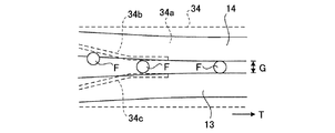
図6に平面図で示すように、吸着コンベア34により上方から保持されて搬送される錠剤Fは、一対のセンタリングガイド34b,34cにより、コンベアベルト34aの表面(下面)に沿って移動して位置調整が行われ、搬送ベルト13,14の隙間Gに上方から案内される。この隙間Gは、隙間調整部材15(図1参照)により、搬送方向Tに向けて徐々に狭まるため、吸着コンベア34に吸着された錠剤Fは、搬送に伴い搬送ベルト13,14間に挟持されて、搬送装置10に順次引き渡される。
As shown in the plan view of FIG. 6, the tablet F held and conveyed from above by the
図1および図2に示すように、撮像装置20は、搬送ベルト13,14間に挟持されて搬送される錠剤の表裏面に対応してそれぞれ配置された一対の反射体21,22と、一対の反射体21,22を介して錠剤の表裏面を撮像するカメラ部23と、カメラ部23により撮像される錠剤を照明する光源部24,25とを備えている。一対の反射体21,22、カメラ部23および光源部24,25は、不図示のブラケットに支持されている。
As shown in FIGS. 1 and 2, the
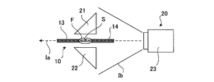
図7は、図1に示す撮像装置20を矢示B方向に見た側面図であり、光源部24,25の図示は省略している。一対の反射体21,22はプリズムからなり、光源部から照射されて錠剤Fの表裏面で反射した照明光が、一対の反射体21,22でそれぞれ反射してカメラ部23で受光される。カメラ部23は、撮像軸Iaが、錠剤Fの表裏面の間を、搬送面に沿って搬送方向(図7の貫通方向)と直交方向に貫通するように配置されており、錠剤Fの表裏面を同時に撮像できるように、撮像範囲Ibが設定されている。一対の反射体21,22は、プリズム以外に鏡や反射板などであってもよい。
FIG. 7 is a side view of the
カメラ部23で撮像された撮像データは、演算装置100に入力される。演算装置100は、入力された撮像データに基づき、錠剤Fの表裏面における割線の有無、割線を有する面(割線面)の割線の位置および方向、割線を有しない面(非割線面)における割線に対応する位置および方向等の、割線に関する割線情報を演算する。
The imaged data captured by the
図1に示すように、印刷装置3は、インクジェット印刷装置からなる第1の印刷部4および第2の印刷部5を備えている。第1の印刷部4および第2の印刷部5は、第2のプーリ12よりも搬送方向上流側と搬送方向下流側のそれぞれにおいて、搬送ベルト13,14の上方に配置されており、演算装置100が演算した割線情報に基づいて、搬送中の錠剤Fの表裏面にそれぞれ印刷する。第1の印刷部4および第2の印刷部5の搬送方向下流側には、それぞれが印刷した後の印字検査等を行う印字検査装置6,7が配置されている。印刷装置3は、インクジェット印刷装置以外に、例えばレーザ印刷装置であってもよい。この場合、所定の錠剤搬送位置の上下にレーザ印刷装置をそれぞれ配置することで、錠剤の表裏面への印刷を同じ位置で同時に行うことができる。
As shown in FIG. 1, the
搬送装置10の搬送方向下流側には、排出装置50が配置されている。排出装置50は、搬送装置10から引き渡された錠剤を搬送する排出コンベア51と、排出コンベア51により搬送される錠剤の良品を選別する選別装置52と、錠剤の良品がダンパ53を介して案内される良品コンベア54と、良品コンベア54により搬送される錠剤の良品が排出される排出シュート55とを備えている。排出コンベア51の上方には、錠剤の側面を検査するための側面検査装置8が設けられている。
A
選別装置52は、印字検査装置6,7および側面検査装置8の検出に基づいて、搬送される錠剤が良品か否かを選別し、良品と選別した錠剤を、エア噴射により良品コンベア54に供給する。ダンパ53は、選別装置52から供給された錠剤を系外ボックス56に供給するように、切り替え可能である。排出装置50は、選別装置52を通過した錠剤の不良品を不良品ボックス58に排出する不良品排出シュート57を更に備えている。
The sorting
上記の構成を備える錠剤印刷装置1によれば、表裏面の一方のみに割線を有する錠剤Fを供給装置30のホッパー31に予め投入しておき、供給装置30から割線情報取得装置2に供給された錠剤Fが、搬送装置10による搬送中に撮像装置20により撮像されて、演算装置100により割線情報の取得が行われる。印刷装置3は、取得された割線情報に基づいて錠剤Fの表裏面に印刷を行い、検査後に排出装置50に引き渡されて、錠剤Fの良品のみが回収される。搬送装置10は、搬送ベルト13,14により搬送中の錠剤Fの挟持位置を一定に維持するため、錠剤の挟持位置以外の露出領域を広範囲に確保することができる。したがって、錠剤Fの表裏面に対する撮像や印刷を容易に行うことができる。
According to the tablet printing device 1 having the above configuration, the tablet F having a score line on only one of the front and back surfaces is charged into the
図8は、撮像装置20による錠剤Fの撮像データの一例を示している。錠剤Fの表裏面の画像は、割線情報取得装置2により同じ搬送位置において同時に取得されるため、錠剤Fの表裏面の画像を切り出して重ね合わせることにより、錠剤Fの割線面に形成された割線Sの位置および方向に関する割線情報を、錠剤Fの非割線面に精度良く反映させることができる。したがって、錠剤Fの非割線面における割線情報(図8に二点鎖線で示すように、割線面の割線Sに対応する位置および方向に関する情報)を、単一のカメラ部23によって正確に取得することができる。
FIG. 8 shows an example of imaging data of tablet F by the
印刷装置3は、割線情報取得装置2が取得した割線情報に基づいて錠剤Fの表裏面に印刷を行うことにより、錠剤Fの表裏両面で印刷の向きを精度良く合わせることができる。したがって、例えば、錠剤Fの割線面に対して文字や記号等を割線に沿って印刷できる一方、錠剤Fの非割線面に対しては、割線面の割線に対応する位置を避けて印刷を行うことができる。
By printing on the front and back surfaces of the tablet F based on the score line information acquired by the score line
本実施形態の割線情報取得装置2が備える搬送装置10は、複数の搬送ベルト13,14の側面間で錠剤Fを挟持して、錠剤Fを搬送するように構成されているが、錠剤Fを表裏面が露出した状態で搬送可能な構成であれば、その構成は特に限定されるものではない。例えば、錠剤を起立させた状態で、錠剤の側面を搬送ローラやベルトコンベア等の搬送面に吸着保持し、搬送方向両側に配置した一対の反射体を介して錠剤を撮像するように構成することもできる。
The
1 錠剤印刷装置
2 割線情報取得装置
3 印刷装置
10 搬送装置
11 第1のプーリ
12 第2のプーリ
13,14 搬送ベルト
20 撮像装置
100 演算装置
F 錠剤
1
Claims (4)
錠剤を表裏面が露出した状態で搬送する搬送装置と、
前記搬送装置により搬送される錠剤の表裏面を撮像する撮像装置と、
前記撮像装置の撮像データに基づいて錠剤の割線情報を演算する演算装置とを備え、
前記撮像装置は、搬送中の錠剤の表裏面に対応してそれぞれ配置された一対の反射体と、一対の前記反射体を介して錠剤の表裏面を同時に撮像するカメラ部とを備え、
前記演算装置は、割線を有する割線面が錠剤の表裏面のいずれであるかを判別し、割線面の画像データから抽出した割線に基づいて、非割線面における割線情報を取得する割線情報取得装置。 It is a score line information acquisition device that acquires score line information of tablets having a score line on only one of the front and back surfaces.
A transport device that transports tablets with the front and back exposed
An imaging device that captures the front and back surfaces of tablets transported by the transport device, and
It is provided with an arithmetic unit that calculates the score line information of the tablet based on the imaging data of the imaging apparatus.
The imaging device includes a pair of reflectors arranged corresponding to the front and back surfaces of the tablet being transported, and a camera unit that simultaneously images the front and back surfaces of the tablet via the pair of reflectors.
The arithmetic unit determines which of the front and back surfaces of the tablet is the score line having the score line, and acquires the score line information on the non-secant line surface based on the score line extracted from the image data of the score line surface. ..
複数の前記搬送ベルトは、対向する側面の間で錠剤を挟持する請求項1に記載の割線情報取得装置。 The transport device includes a pair of pulleys and a plurality of endless strip-shaped transport belts wound between the pair of pulleys at intervals.
The score line information acquisition device according to claim 1, wherein the plurality of transport belts sandwich a tablet between opposite side surfaces.
前記割線情報取得装置が取得した割線情報に基づいて錠剤の表裏面に印刷を行う印刷装置とを備える錠剤印刷装置。 The secant information acquisition device according to any one of claims 1 to 3 and
A tablet printing device including a printing device that prints on the front and back surfaces of a tablet based on the dividing line information acquired by the dividing line information acquisition device.
Priority Applications (1)
| Application Number | Priority Date | Filing Date | Title |
|---|---|---|---|
| JP2019079038A JP2020174902A (en) | 2019-04-18 | 2019-04-18 | Secant line information acquisition device and tablet printing device |
Applications Claiming Priority (1)
| Application Number | Priority Date | Filing Date | Title |
|---|---|---|---|
| JP2019079038A JP2020174902A (en) | 2019-04-18 | 2019-04-18 | Secant line information acquisition device and tablet printing device |
Publications (1)
| Publication Number | Publication Date |
|---|---|
| JP2020174902A true JP2020174902A (en) | 2020-10-29 |
Family
ID=72936932
Family Applications (1)
| Application Number | Title | Priority Date | Filing Date |
|---|---|---|---|
| JP2019079038A Pending JP2020174902A (en) | 2019-04-18 | 2019-04-18 | Secant line information acquisition device and tablet printing device |
Country Status (1)
| Country | Link |
|---|---|
| JP (1) | JP2020174902A (en) |
Citations (7)
| Publication number | Priority date | Publication date | Assignee | Title |
|---|---|---|---|---|
| JP2004537868A (en) * | 2001-08-09 | 2004-12-16 | インテグレイテッド ダイナミックス エンジニアリング インコーポレーテッド | Edge gripping pre-aligner |
| JP2014095574A (en) * | 2012-11-08 | 2014-05-22 | Denso Corp | Appearance inspection device |
| WO2016092673A1 (en) * | 2014-12-11 | 2016-06-16 | 富士機械製造株式会社 | Component-mounting machine |
| JP2017158947A (en) * | 2016-03-11 | 2017-09-14 | フロイント産業株式会社 | Tablet printing device, tablet printing method, and medicine management system |
| JP2017225784A (en) * | 2016-06-25 | 2017-12-28 | フロイント産業株式会社 | Tablet mark printing method, tablet mark printer, and tablet |
| WO2018100980A1 (en) * | 2016-11-30 | 2018-06-07 | クオリカプス株式会社 | Pharmaceutical preparation conveying device and pharmaceutical preparation printing device |
| JP2018183671A (en) * | 2018-08-29 | 2018-11-22 | 株式会社Screenホールディングス | Tablet printing method |
-
2019
- 2019-04-18 JP JP2019079038A patent/JP2020174902A/en active Pending
Patent Citations (7)
| Publication number | Priority date | Publication date | Assignee | Title |
|---|---|---|---|---|
| JP2004537868A (en) * | 2001-08-09 | 2004-12-16 | インテグレイテッド ダイナミックス エンジニアリング インコーポレーテッド | Edge gripping pre-aligner |
| JP2014095574A (en) * | 2012-11-08 | 2014-05-22 | Denso Corp | Appearance inspection device |
| WO2016092673A1 (en) * | 2014-12-11 | 2016-06-16 | 富士機械製造株式会社 | Component-mounting machine |
| JP2017158947A (en) * | 2016-03-11 | 2017-09-14 | フロイント産業株式会社 | Tablet printing device, tablet printing method, and medicine management system |
| JP2017225784A (en) * | 2016-06-25 | 2017-12-28 | フロイント産業株式会社 | Tablet mark printing method, tablet mark printer, and tablet |
| WO2018100980A1 (en) * | 2016-11-30 | 2018-06-07 | クオリカプス株式会社 | Pharmaceutical preparation conveying device and pharmaceutical preparation printing device |
| JP2018183671A (en) * | 2018-08-29 | 2018-11-22 | 株式会社Screenホールディングス | Tablet printing method |
Similar Documents
| Publication | Publication Date | Title |
|---|---|---|
| US11008170B2 (en) | Pharmaceutical formulation transporting device and pharmaceutical formulation printing device | |
| JP2009002692A (en) | Inspected object conveying device and appearance inspection device | |
| JP2009208963A (en) | Conveyor reversing device, and inspection device using the same | |
| JP2001327929A (en) | Device for inspecting work | |
| JP2012046280A (en) | Container conveying apparatus | |
| JP5879576B2 (en) | Container transfer device | |
| JP6282468B2 (en) | Transport device | |
| JP2018117949A (en) | Tablet printing apparatus | |
| JP4310616B2 (en) | Appearance inspection machine for flat tablets | |
| JP7115905B2 (en) | Small article processing system | |
| JP7323344B2 (en) | Secant information acquisition device and tablet printing device | |
| JP2020174902A (en) | Secant line information acquisition device and tablet printing device | |
| JP3553832B2 (en) | Transfer device, inspection device and alignment supply device | |
| JP4275875B2 (en) | Parts inspection device | |
| CN118190803A (en) | Inspection device and inspection method for annular substrate | |
| JP2019058221A (en) | Tablet printing device | |
| KR101158680B1 (en) | Vision inspection apparatus for flat type frame | |
| JP3770996B2 (en) | Inspection device for bag making product and inspection method for bag making product | |
| JP2021087971A (en) | Laser processing device | |
| JP7607405B2 (en) | Apparatus and method for inspecting film laminate | |
| JP2017119565A (en) | Conveying device and inspection device | |
| CA3039887C (en) | Pharmaceutical formulation transporting device and pharmaceutical formulation printing device | |
| JP4056810B2 (en) | Container inspection device and container inspection system using this device | |
| JP2020081219A (en) | Tablet printing equipment | |
| JP2904446B2 (en) | Inspection equipment for circular articles |
Legal Events
| Date | Code | Title | Description |
|---|---|---|---|
| A621 | Written request for application examination |
Free format text: JAPANESE INTERMEDIATE CODE: A621 Effective date: 20220323 |
|
| A131 | Notification of reasons for refusal |
Free format text: JAPANESE INTERMEDIATE CODE: A131 Effective date: 20221223 |
|
| A977 | Report on retrieval |
Free format text: JAPANESE INTERMEDIATE CODE: A971007 Effective date: 20221227 |
|
| A02 | Decision of refusal |
Free format text: JAPANESE INTERMEDIATE CODE: A02 Effective date: 20230310 |