JP2020200031A - Railway vehicle - Google Patents

Railway vehicle Download PDF

Info

Publication number
JP2020200031A
JP2020200031A JP2020098237A JP2020098237A JP2020200031A JP 2020200031 A JP2020200031 A JP 2020200031A JP 2020098237 A JP2020098237 A JP 2020098237A JP 2020098237 A JP2020098237 A JP 2020098237A JP 2020200031 A JP2020200031 A JP 2020200031A
Authority
JP
Japan
Prior art keywords
panel
ceiling
overhanging portion
rail direction
panels
Prior art date
Legal status (The legal status is an assumption and is not a legal conclusion. Google has not performed a legal analysis and makes no representation as to the accuracy of the status listed.)
Granted
Application number
JP2020098237A
Other languages
Japanese (ja)
Other versions
JP7413152B2 (en
Inventor
剛司 大西
Goji Onishi
剛司 大西
亮二 小畑
Ryoji Obata
亮二 小畑
佑介 玉川
Yusuke Tamagawa
佑介 玉川
勝太 中村
Shota Nakamura
勝太 中村
優太 眞野
Yuta Mano
優太 眞野
Current Assignee (The listed assignees may be inaccurate. Google has not performed a legal analysis and makes no representation or warranty as to the accuracy of the list.)
Nippon Sharyo Ltd
Original Assignee
Nippon Sharyo Ltd
Priority date (The priority date is an assumption and is not a legal conclusion. Google has not performed a legal analysis and makes no representation as to the accuracy of the date listed.)
Filing date
Publication date
Application filed by Nippon Sharyo Ltd filed Critical Nippon Sharyo Ltd
Publication of JP2020200031A publication Critical patent/JP2020200031A/en
Application granted granted Critical
Publication of JP7413152B2 publication Critical patent/JP7413152B2/en
Active legal-status Critical Current
Anticipated expiration legal-status Critical

Links

Images

Landscapes

  • Bridges Or Land Bridges (AREA)

Abstract

【課題】天井パネルの着脱時に張出部を突出部に干渉し難くできる鉄道車両を提供すること。【解決手段】鉄道車両は、レール方向に並んで天井の少なくとも一部を形成する複数の天井パネルと、複数の天井パネルの間からそれぞれ下方へ突出する複数の突出部と、を備え、天井パネルは、レール方向の端縁が突出部とレール方向に対向するパネル本体と、パネル本体の端縁のうち枕木方向の片側のみからレール方向に張り出して突出部の枕木方向の片側に位置する張出部と、を備えている。【選択図】図2PROBLEM TO BE SOLVED: To provide a railroad vehicle capable of making it difficult for an overhanging portion to interfere with a protruding portion when attaching / detaching a ceiling panel. SOLUTION: A railroad vehicle includes a plurality of ceiling panels lining up in a rail direction to form at least a part of a ceiling, and a plurality of protrusions protruding downward from between the plurality of ceiling panels. Is a panel body whose end edge in the rail direction faces the projecting portion in the rail direction, and an overhang located on one side of the edge of the panel body in the railroad direction, protruding in the rail direction from only one side in the sleeper direction. It has a department and. [Selection diagram] Fig. 2

Description

本発明は、天井パネルの着脱時に張出部を突出部に干渉し難くできる鉄道車両に関するものである。 The present invention relates to a railway vehicle capable of making it difficult for the overhanging portion to interfere with the protruding portion when the ceiling panel is attached or detached.

レール方向に並ぶ複数の天井パネルにより天井の一部が形成され、吊手などを吊る吊手棒を支持する吊手棒受けなどの複数の突出部が、複数の天井パネルの間からそれぞれ下方へ突出する鉄道車両がある。特許文献1には、天井パネルのパネル本体のレール方向の両端縁において、それぞれ枕木方向の両側から張出部をレール方向に張り出させ、その張出部を突出部の枕木方向の両側に位置させる鉄道車両が開示されている。 A part of the ceiling is formed by a plurality of ceiling panels arranged in the rail direction, and a plurality of protrusions such as a hanger bar holder for supporting a hanger bar for hanging a hanger or the like are projected downward from between the plurality of ceiling panels. There is a protruding railroad car. In Patent Document 1, at both end edges of the panel body of the ceiling panel in the rail direction, overhangs are projected from both sides in the sleeper direction in the rail direction, and the overhangs are located on both sides of the protrusion in the railroad direction. The railroad vehicle to be operated is disclosed.

特開2005−350033号公報JP-A-2005-35533

しかしながら、上記従来の技術では、天井パネルの着脱時に張出部が突出部に干渉し易いという問題点がある。 However, the above-mentioned conventional technique has a problem that the overhanging portion easily interferes with the protruding portion when the ceiling panel is attached or detached.

本発明は上述した問題点を解決するためになされたものであり、天井パネルの着脱時に張出部を突出部に干渉し難くできる鉄道車両を提供することを目的とする。 The present invention has been made to solve the above-mentioned problems, and an object of the present invention is to provide a railway vehicle capable of making it difficult for the overhanging portion to interfere with the protruding portion when the ceiling panel is attached or detached.

この目的を達成するために本発明の鉄道車両は、レール方向に並んで天井の少なくとも一部を形成する複数の天井パネルと、複数の前記天井パネルの間からそれぞれ下方へ突出する複数の突出部と、を備え、前記天井パネルは、レール方向の端縁が前記突出部とレール方向に対向するパネル本体と、前記パネル本体の前記端縁のうち枕木方向の片側のみからレール方向に張り出して前記突出部の枕木方向の片側に位置する張出部と、を備えている。 In order to achieve this object, the railroad vehicle of the present invention has a plurality of ceiling panels lining up in the rail direction to form at least a part of the ceiling, and a plurality of protrusions protruding downward from between the plurality of ceiling panels. The ceiling panel is provided with a panel body whose end edge in the rail direction faces the projecting portion in the rail direction, and the ceiling panel projecting in the rail direction from only one side of the end edge of the panel body in the sleeper direction. It is provided with an overhanging portion located on one side of the protruding portion in the direction of the sleepers.

また、本発明の鉄道車両は、レール方向に並んで天井の少なくとも一部を形成する複数の天井パネルと、複数の前記天井パネルの間からそれぞれ下方へ突出する複数の突出部と、を備え、前記天井パネルは、レール方向の端縁が前記突出部とレール方向に対向するパネル本体と、前記パネル本体のレール方向片側の前記端縁のみからレール方向に張り出すと共に、前記突出部の枕木方向の両側にそれぞれ位置する一対の張出部と、を備えている。 Further, the railroad vehicle of the present invention includes a plurality of ceiling panels lining up in the rail direction to form at least a part of the ceiling, and a plurality of projecting portions protruding downward from between the plurality of ceiling panels. The ceiling panel projects in the rail direction from only the panel body whose rail-direction edge faces the projecting portion in the rail direction and the end edge on one side of the panel body in the rail direction, and the projecting portion in the railroad tie direction. It is provided with a pair of overhangs located on both sides of the rail.

請求項1記載の鉄道車両によれば、パネル本体の端縁のうち枕木方向の片側のみからレール方向に張出部が張り出し、その張出部が突出部の枕木方向の片側に位置する。そのため、天井パネルの着脱時に、片側の張出部が突出部に干渉しないように気を付けながら、張出部を突出部から離したり近づけたりして天井パネルを動かすことができる。これにより、パネル本体の端縁のうち枕木方向の両側から張出部が張り出している場合と比べて、天井パネルの着脱時に張出部を突出部に干渉し難くできる。 According to the railway vehicle according to claim 1, an overhanging portion projects in the rail direction from only one side of the edge of the panel body in the sleeper direction, and the overhanging portion is located on one side of the protruding portion in the sleeper direction. Therefore, when the ceiling panel is attached or detached, the ceiling panel can be moved by moving the overhanging portion away from or closer to the protruding portion while being careful not to interfere with the protruding portion on one side. As a result, it is possible to make it less likely that the overhanging portion interferes with the protruding portion when the ceiling panel is attached or detached, as compared with the case where the overhanging portion of the edge of the panel body projects from both sides in the sleeper direction.

請求項2記載の鉄道車両によれば、張出部は、パネル本体のレール方向の一方の端縁から張り出す第1張出部と、パネル本体のレール方向の他方の端縁から張り出す第2張出部と、を備えている。この第1張出部と第2張出部とが枕木方向に突出部を挟んで対向する。これにより、請求項1の効果に加え、パネル本体の端縁の枕木方向の両側から張出部が張り出す場合と同様に、突出部の略全周を2枚の天井パネルで囲みながら、天井パネルの着脱時に張出部を突出部に干渉し難くできる。 According to the railway vehicle according to claim 2, the overhanging portion is a first overhanging portion that projects from one end edge of the panel body in the rail direction and a first overhanging portion that projects from the other end edge of the panel body in the rail direction. It has two overhangs. The first overhanging portion and the second overhanging portion face each other with the protruding portion in the sleeper direction. As a result, in addition to the effect of claim 1, the ceiling is surrounded by two ceiling panels on substantially the entire circumference of the protruding portion, as in the case where the protruding portions project from both sides of the edge of the panel body in the sleeper direction. It is possible to prevent the overhanging portion from interfering with the protruding portion when the panel is attached or detached.

請求項3記載の鉄道車両によれば、張出部は、パネル本体のレール方向の一方の端縁から張り出す第1張出部と、パネル本体のレール方向の他方の端縁から張り出す第2張出部と、を備えている。1枚の天井パネルにそれぞれ設けられる第1張出部および第2張出部が枕木方向の同一側に位置する。これにより、天井パネルをレール方向に傾けなくても、天井パネルを枕木方向や下方へスライドして天井パネルを着脱できる。その結果、請求項1又は2に効果に加え、天井パネルの着脱時に張出部を突出部に更に干渉し難くできる。 According to the railway vehicle according to claim 3, the overhanging portion is a first overhanging portion that projects from one end edge of the panel body in the rail direction and a first overhanging portion that projects from the other end edge of the panel body in the rail direction. It has two overhangs. The first overhang and the second overhang provided on one ceiling panel are located on the same side in the sleeper direction. As a result, the ceiling panel can be attached and detached by sliding the ceiling panel toward the sleepers or downward without tilting the ceiling panel toward the rail. As a result, in addition to the effect of claim 1 or 2, the overhanging portion can be made less likely to interfere with the protruding portion when the ceiling panel is attached or detached.

請求項4記載の鉄道車両によれば、複数の天井パネルは、突出部に対して枕木方向の第1側に第1張出部および第2張出部が位置する第1パネルと、突出部に対して枕木方向のうち第1側とは反対の第2側に第1張出部および第2張出部が位置する第2パネルと、を備えている。パネル本体の端縁の間から下方へ向かうにつれて第1側へ突出部が傾斜している。そのため、第1パネルを下方へスライドするとき、第1パネルの張出部が突出部に干渉し易くなる一方で、第2パネルを下方へスライドするとき、第2パネルの張出部を突出部に干渉し難くできる。即ち、第1パネルよりも第2パネルを着脱し易くできる。 According to the railway vehicle according to claim 4, the plurality of ceiling panels include a first panel in which the first overhanging portion and the second overhanging portion are located on the first side in the sleeper direction with respect to the protruding portion, and the protruding portion. It is provided with a second panel in which the first overhanging portion and the second overhanging portion are located on the second side opposite to the first side in the direction of the sleepers. The protrusion is inclined toward the first side as it goes downward from between the edges of the panel body. Therefore, when the first panel is slid downward, the overhanging portion of the first panel easily interferes with the protruding portion, while when the second panel is slid downward, the overhanging portion of the second panel is projected. Can be less likely to interfere with. That is, the second panel can be attached and detached more easily than the first panel.

天井のレール方向の両端間において、レール方向に隣り合う突出部同士の間隔が最大となる最大部が少なくとも1か所あるので、最大部に配置される天井パネルのパネル本体が長くなって、その天井パネルを着脱し難くなる。上述した通り第1パネルよりも第2パネルを着脱し易いので、天井のレール方向の両端間において、最大部に配置される第2パネルの数が、最大部に配置される第1パネルの数以上になるように、第1パネルと第2パネルとをレール方向に交互に配置することで、請求項3の効果に加え、複数の天井パネルの着脱作業を容易にできる。 Since there is at least one maximum portion between both ends of the ceiling in the rail direction that maximizes the distance between the protrusions adjacent to each other in the rail direction, the panel body of the ceiling panel arranged at the maximum portion becomes long. It becomes difficult to attach and detach the ceiling panel. As described above, since the second panel is easier to attach and detach than the first panel, the number of the second panels arranged in the maximum portion between both ends in the rail direction of the ceiling is the number of the first panels arranged in the maximum portion. By arranging the first panel and the second panel alternately in the rail direction as described above, in addition to the effect of claim 3, it is possible to easily attach / detach a plurality of ceiling panels.

請求項5記載の鉄道車両によれば、複数の天井パネルは、突出部に対して枕木方向の第1側に第1張出部および第2張出部が位置する第1パネルと、突出部に対して枕木方向のうち第1側とは反対の第2側に第1張出部および第2張出部が位置する第2パネルと、を備えている。パネル本体の端縁の間から下方へ向かうにつれて第1側へ突出部が傾斜している。そのため、第1パネルを下方へスライドするとき、第1パネルの張出部が突出部に干渉し易くなる一方で、第2パネルを下方へスライドするとき、第2パネルの張出部を突出部に干渉し難くできる。即ち、第1パネルよりも第2パネルを着脱し易くできる。 According to the railway vehicle according to claim 5, the plurality of ceiling panels include a first panel in which the first overhanging portion and the second overhanging portion are located on the first side in the sleeper direction with respect to the protruding portion, and the protruding portion. It is provided with a second panel in which the first overhanging portion and the second overhanging portion are located on the second side opposite to the first side in the direction of the sleepers. The protrusion is inclined toward the first side as it goes downward from between the edges of the panel body. Therefore, when the first panel is slid downward, the overhanging portion of the first panel easily interferes with the protruding portion, while when the second panel is slid downward, the overhanging portion of the second panel is projected. Can be less likely to interfere with. That is, the second panel can be attached and detached more easily than the first panel.

天井のレール方向の両端間において、レール方向に隣り合う突出部同士の間隔が少なくとも一部異なり、その間隔に応じて天井パネルのパネル本体が長くなる程、その天井パネルを着脱し難くなる。天井のレール方向の両端間において、そのレール方向の一端から奇数番目における間隔の合計と、偶数番目における間隔の合計とを比較して、その合計が小さい方に比較的着脱し難い第1パネルを配置し、合計が大きい方に比較的着脱し易い第2パネルを配置することで、請求項3又は4の効果に加え、複数の天井パネルの着脱作業を容易にできる。 The distance between the protrusions adjacent to each other in the rail direction is at least partially different between both ends in the rail direction of the ceiling, and the longer the panel body of the ceiling panel is according to the distance, the more difficult it becomes to attach and detach the ceiling panel. Between both ends of the ceiling in the rail direction, the total distance from one end in the rail direction to the odd number is compared with the total distance in the even number, and the smaller total is the first panel that is relatively difficult to attach and detach. By arranging the second panel, which is relatively easy to attach / detach to the one having the larger total, in addition to the effect of claim 3 or 4, it is possible to easily attach / detach a plurality of ceiling panels.

請求項6記載の鉄道車両によれば、パネル本体のレール方向片側の端縁のみから一対の張出部がレール方向にそれぞれ張り出し、その一対の張出部が突出部の枕木方向の両側にそれぞれ位置する。そのため、天井パネルを取り外すには、一対の張出部がある端縁を支点にしながら一対の張出部がない端縁を下方に移動させて、天井パネルを傾けた後、一対の張出部がある端縁を突出部から離すように天井パネルをスライドや回転させる。天井パネルを取り付けるには、この逆の工程を行う。これにより、一対の張出部がパネル本体のレール方向の両端縁から張り出している場合と比べて、天井パネルの着脱時に一対の張出部を突出部に干渉し難くできる。 According to the railway vehicle according to claim 6, a pair of overhangs project in the rail direction from only one end edge of the panel body in the rail direction, and the pair of overhangs project on both sides of the projecting portion in the sleeper direction. To position. Therefore, in order to remove the ceiling panel, the edge with the pair of overhangs is used as a fulcrum, the edge without the pair of overhangs is moved downward, the ceiling panel is tilted, and then the pair of overhangs is removed. Slide or rotate the ceiling panel so that some edges are separated from the protrusions. To install the ceiling panel, reverse the process. As a result, the pair of overhanging portions can be less likely to interfere with the protruding portions when the ceiling panel is attached or detached, as compared with the case where the pair of overhanging portions project from both end edges in the rail direction of the panel body.

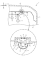
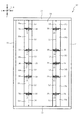
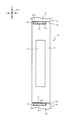
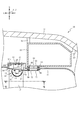
第1実施形態における鉄道車両の断面図である。It is sectional drawing of the railroad vehicle in 1st Embodiment. 図1のII−II線における鉄道車両の断面図である。It is sectional drawing of the railroad vehicle in line II-II of FIG. 複数の天井パネルを並べた鉄道車両の天井の模式図であるIt is a schematic diagram of the ceiling of a railroad vehicle in which a plurality of ceiling panels are arranged. 第2実施形態における鉄道車両の断面図である。It is sectional drawing of the railroad vehicle in 2nd Embodiment. 第3実施形態における鉄道車両の断面図である。It is sectional drawing of the railroad vehicle in 3rd Embodiment. 第4実施形態における鉄道車両の断面図である。It is sectional drawing of the railroad vehicle in 4th Embodiment. 図6のVII−VII線における鉄道車両の断面図である。It is sectional drawing of the railroad vehicle in the VII-VII line of FIG.

以下、好ましい実施形態について、添付図面を参照して説明する。まず、図1及び図2を参照して第1実施形態における鉄道車両10について説明する。図1は鉄道車両10のレール方向に垂直な断面図である。図2は図1のII−II線における鉄道車両10の断面図であり、1枚の外側パネル30が拡大して示されている。なお、図1では、左右略対称に形成される鉄道車両10の左側を省略し、鉄道車両10の下部を省略し、屋根構体12と天井板14との間に設置される各部材の図示を省略している。また、説明の便宜上、各図面における矢印U方向を鉄道車両10の上方向とし、同様に、矢印D方向を下方向、矢印L方向を左方向、矢印R方向を右方向、矢印F方向を前方向、矢印B方向を後方向とする。 Hereinafter, preferred embodiments will be described with reference to the accompanying drawings. First, the railway vehicle 10 according to the first embodiment will be described with reference to FIGS. 1 and 2. FIG. 1 is a cross-sectional view of the railroad vehicle 10 perpendicular to the rail direction. FIG. 2 is a cross-sectional view of the railroad vehicle 10 on the line II-II of FIG. 1, and one outer panel 30 is enlarged and shown. In FIG. 1, the left side of the railroad vehicle 10 formed substantially symmetrically is omitted, the lower part of the railroad car 10 is omitted, and each member installed between the roof structure 12 and the ceiling plate 14 is illustrated. It is omitted. Further, for convenience of explanation, the arrow U direction in each drawing is the upward direction of the railway vehicle 10, similarly, the arrow D direction is the downward direction, the arrow L direction is the left direction, the arrow R direction is the right direction, and the arrow F direction is the front direction. The direction and the direction of arrow B are the backward directions.

図1に示すように、鉄道車両10は、台枠(図示せず)と、台枠の枕木方向(左右方向)の両側に立設される側構体11と、側構体11の上部に設置される屋根構体12と、台枠のレール方向(前後方向)の両側に立設される妻構体13と、を備えている。屋根構体12は、図示しない支持部材によって客室の天井板14を吊り下げ支持する。鉄道車両10は、左右略対称に形成されているので、特に指示がない限り鉄道車両10の右側を説明し、左側の説明を省略する。 As shown in FIG. 1, the railroad vehicle 10 is installed on the underframe (not shown), the side structures 11 erected on both sides of the underframe in the sleeper direction (left-right direction), and the upper part of the side structures 11. The roof structure 12 and the wife structure 13 erected on both sides of the underframe in the rail direction (front-rear direction) are provided. The roof structure 12 suspends and supports the ceiling plate 14 of the guest room by a support member (not shown). Since the railway vehicle 10 is formed substantially symmetrically to the left and right, the right side of the railway vehicle 10 will be described and the description on the left side will be omitted unless otherwise specified.

天井板14は、客室の天井の大部分を形成する部位である。天井板14には、上方(屋根構体12側)へ凹んだ溝部14aがレール方向に連続して形成されている。溝部14aは、天井板14の左右両側にそれぞれ設けられている。 The ceiling plate 14 is a portion that forms most of the ceiling of the guest room. Grooves 14a recessed upward (on the roof structure 12 side) are continuously formed in the ceiling plate 14 in the rail direction. Grooves 14a are provided on both the left and right sides of the ceiling plate 14, respectively.

この溝部14aの溝底には、レール方向に間隔をあけて複数の吊手棒受け(突出部)15が取り付けられている。さらに、その複数の吊手棒受け15の間に複数の照明器具22が配置され、その照明器具22が支持部材20を介して溝部14aの溝底に取り付けられている。 A plurality of suspension rod receivers (protruding portions) 15 are attached to the groove bottom of the groove portion 14a at intervals in the rail direction. Further, a plurality of lighting fixtures 22 are arranged between the plurality of hanging handle bar receivers 15, and the lighting fixtures 22 are attached to the groove bottom of the groove portion 14a via the support member 20.

吊手棒受け15は、前後両面がレール方向に略垂直な板状の金属部材であり、幅が上端から下端へ向かうにつれて小さくなる。吊手棒受け15は、上端からレール方向に張り出すフランジ15aが溝部14aの溝底にボルト15bによって取り付けられている。吊手棒受け15は、フランジ15aから吊手棒受け15の下端へ向かうにつれて枕木方向の車両中央側(第1側)に湾曲(傾斜)する。 The hanger bar holder 15 is a plate-shaped metal member whose front and rear surfaces are substantially perpendicular to the rail direction, and its width decreases from the upper end to the lower end. In the hanging bar holder 15, a flange 15a projecting from the upper end in the rail direction is attached to the groove bottom of the groove portion 14a by a bolt 15b. The hanger bar receiver 15 curves (inclines) toward the vehicle center side (first side) in the sleeper direction toward the lower end of the hanger bar receiver 15 from the flange 15a.

レール方向に並んだ複数の吊手棒受け15の下端には、レール方向に長い吊手棒16が支持されている。左右対称に配置された吊手棒16には、枕木方向に長い複数の吊手棒17がレール方向に間隔をあけて架け渡される。この吊手棒16,17には、立っている乗客が掴む吊手18,19がそれぞれ吊り下げられる。 At the lower ends of the plurality of hanging hand rod receivers 15 arranged in the rail direction, a hanging hand rod 16 long in the rail direction is supported. A plurality of suspension rods 17 long in the sleeper direction are bridged to the suspension rods 16 symmetrically arranged at intervals in the rail direction. Hangers 18 and 19 gripped by standing passengers are hung from the hanger rods 16 and 17, respectively.

照明器具22は、客室内部を照らす照明本体23と、その照明本体23を覆う半透明の半円筒状のカバー24と、を備えている。照明本体23は、ボルト25により支持部材20に取り付けられる。そして、この支持部材20がボルト21により溝部14aの溝底に取り付けられることで、枕木方向の車両中央側へ若干傾いた状態で照明器具22が天井板14に固定される。なお、この照明器具22の直下に吊手棒16が位置して客室が暗くならないように、吊手棒受け15を湾曲させて吊手棒16と照明器具22とを枕木方向に離している。 The lighting fixture 22 includes a lighting main body 23 that illuminates the inside of the guest room, and a semi-transparent semi-cylindrical cover 24 that covers the lighting main body 23. The lighting body 23 is attached to the support member 20 by bolts 25. Then, by attaching the support member 20 to the groove bottom of the groove portion 14a by the bolt 21, the luminaire 22 is fixed to the ceiling plate 14 in a state of being slightly tilted toward the center of the vehicle in the direction of the sleepers. The hanging bar 16 and the lighting device 22 are separated from each other in the direction of the sleepers by bending the hanging bar receiver 15 so that the hanging bar 16 is located directly under the lighting fixture 22 and the guest room is not darkened.

図1及び図2に示すように、複数の吊手棒受け15の間には、天井の一部を形成する複数の天井パネルとしての外側パネル(第2パネル)30及び内側パネル(第1パネル)35が交互にレール方向に並んでいる。外側パネル30及び内側パネル35は、照明本体23の天井板14側に重ねられ、ボルト25によって照明本体23と共に支持部材20に取り付けられる。 As shown in FIGS. 1 and 2, the outer panel (second panel) 30 and the inner panel (first panel) as a plurality of ceiling panels forming a part of the ceiling are sandwiched between the plurality of hanging hand rod receivers 15. ) 35 are alternately arranged in the rail direction. The outer panel 30 and the inner panel 35 are overlapped on the ceiling plate 14 side of the lighting main body 23, and are attached to the support member 20 together with the lighting main body 23 by bolts 25.

支持部材20を介して天井板14に固定された外側パネル30及び内側パネル35によって溝部14aが覆われ、客室内の乗客から吊手棒受け15のフランジ15aやボルト15b、支持部材20、ボルト21を見難くできるので、客室内からの見た目を良くできる。また、外側パネル30及び内側パネル35を天井板14に固定するためのボルト25がカバー24に覆われるので、客室内からの見た目をより良くできる。 The groove 14a is covered by the outer panel 30 and the inner panel 35 fixed to the ceiling plate 14 via the support member 20, and the flange 15a and bolts 15b of the hanging bar holder 15, the support member 20, and the bolt 21 are received from passengers in the cabin. Since it can be difficult to see, you can improve the appearance from inside the guest room. Further, since the bolt 25 for fixing the outer panel 30 and the inner panel 35 to the ceiling plate 14 is covered with the cover 24, the appearance from the inside of the guest room can be improved.

外側パネル30は、パネル本体31と、パネル本体31の前方側の端縁31aから前方に張り出す外前張出部(第1張出部)33と、パネル本体31の後方側の端縁31bから後方に張り出す外後張出部(第2張出部)34と、を備えている。内側パネル35は、パネル本体36と、パネル本体36の前方側の端縁36aから前方に張り出す内前張出部(第1張出部)38と、パネル本体36の後方側の端縁36bから後方に張り出す内後張出部(第2張出部)39と、を備えている。 The outer panel 30 has a panel main body 31, an outer front overhanging portion (first overhanging portion) 33 protruding forward from the front end edge 31a of the panel main body 31, and a rear end edge 31b of the panel main body 31. It is provided with an outer rear overhanging portion (second overhanging portion) 34 that projects rearward from the surface. The inner panel 35 has a panel main body 36, an inner front overhanging portion (first overhanging portion) 38 protruding forward from the front end edge 36a of the panel main body 36, and a rear end edge 36b of the panel main body 36. It is provided with an inner rear overhanging portion (second overhanging portion) 39, which overhangs rearward from the above.

パネル本体31の端縁31aとパネル本体36の端縁36bとの間、パネル本体31の端縁31bとパネル本体36の端縁36aとの間からそれぞれ吊手棒受け15が下方へ突出し、端縁31a,31b,36a,36bが吊手棒受け15とレール方向に対向している。端縁31a,31b,36a,36bは、枕木方向に直線状に形成され、吊手棒受け15よりも枕木方向両側へ張り出している。端縁31a,31b,36a,36bと吊手棒受け15とのレール方向の隙間は、それぞれ枕木方向の全長に亘って略同一であり、吊手棒受け15の厚さ(レール方向寸法)よりも小さい。これにより、端縁31a,31b,36a,36bと吊手棒受け15との隙間を通して溝部14a側を客室から見難くできる。 The hanging hand rod holder 15 projects downward from between the edge 31a of the panel body 31 and the edge 36b of the panel body 36, and between the edge 31b of the panel body 31 and the edge 36a of the panel body 36, respectively, and ends. The edges 31a, 31b, 36a, 36b face the hanging bar holder 15 in the rail direction. The edge edges 31a, 31b, 36a, 36b are formed linearly in the sleeper direction and project from the hanging bar holder 15 to both sides in the sleeper direction. The gaps in the rail direction between the end edges 31a, 31b, 36a, 36b and the hanger bar holder 15 are substantially the same over the entire length in the sleeper direction, and are based on the thickness (rail direction dimension) of the hanger bar holder 15. Is also small. As a result, the groove portion 14a side can be made difficult to see from the passenger compartment through the gap between the end edges 31a, 31b, 36a, 36b and the hanging bar holder 15.

外前張出部33及び外後張出部34は、パネル本体31と一体成形されている。外前張出部33は、端縁31aのうち枕木方向の車両外側(右側、第2側)のみから張り出して、吊手棒受け15に対して枕木方向の車両外側に位置する。外後張出部34は、端縁31bのうち枕木方向の車両外側のみから張り出して、吊手棒受け15に対して枕木方向の車両外側に位置する。 The outer front overhang 33 and the outer back overhang 34 are integrally molded with the panel body 31. The outer front overhanging portion 33 projects from only the outside of the vehicle in the sleeper direction (right side, second side) of the end edge 31a, and is located on the outside of the vehicle in the sleeper direction with respect to the hanging bar holder 15. The outer rear overhanging portion 34 projects from only the outside of the vehicle in the direction of the sleepers among the edge 31b, and is located on the outside of the vehicle in the direction of the sleepers with respect to the hanging bar holder 15.

内前張出部38及び内後張出部39は、パネル本体36と一体成形されている。内前張出部38は、端縁36aのうち枕木方向の車両中央側(左側、第1側)のみから張り出して、吊手棒受け15に対して枕木方向の車両中央側に位置する。内後張出部39は、端縁36bのうち枕木方向の車両中央側のみから張り出して、吊手棒受け15に対して枕木方向の車両中央側に位置する。 The inner front overhang 38 and the inner back overhang 39 are integrally molded with the panel body 36. The inner front overhanging portion 38 projects from only the vehicle center side (left side, first side) in the sleeper direction of the edge 36a, and is located on the vehicle center side in the sleeper direction with respect to the hanging bar holder 15. The inner rear overhanging portion 39 projects from only the vehicle center side in the sleeper direction of the edge 36b, and is located on the vehicle center side in the sleeper direction with respect to the hanging bar holder 15.

このような外側パネル30や内側パネル35は金属製であり、すぐ近くに吊手棒受け15があるため、外側パネル30や内側パネル35の着脱時に、端縁31a,31b,36a,36bや各張出部33,34,38,39の角などが吊手棒受け15に当たると、吊手棒受け15が傷つくことがある。そこで、外側パネル30や内側パネル35を吊手棒受け15に当たらないように、外側パネル30や内側パネル35を着脱することが望まれている。 Since the outer panel 30 and the inner panel 35 are made of metal and there is a hanging bar holder 15 in the immediate vicinity, the end edges 31a, 31b, 36a, 36b and each of them are used when the outer panel 30 and the inner panel 35 are attached and detached. If the corners of the overhanging portions 33, 34, 38, 39 hit the hanging bar holder 15, the hanging bar holder 15 may be damaged. Therefore, it is desired to attach / detach the outer panel 30 and the inner panel 35 so that the outer panel 30 and the inner panel 35 do not hit the hanging bar holder 15.

複数の張出部33,34,38,39は、それぞれ端縁31a,31b,36a,36bのうち枕木方向の片側のみから張り出しているので、外側パネル30や内側パネル35の着脱時に、片側の張出部33,34,38,39が吊手棒受け15に干渉しないように気を付けながら、張出部33,34,38,39を吊手棒受け15から離したり近づけたりして外側パネル30や内側パネル35を動かすことができる。これにより、レール方向の両端縁においてそれぞれ枕木方向の両側から張出部が張り出す従来の天井パネルと比べて、外側パネル30や内側パネル35の着脱時に張出部33,34,38,39を吊手棒受け15に干渉し難くできる。 Since the plurality of overhanging portions 33, 34, 38, 39 project from only one side of the end edges 31a, 31b, 36a, 36b in the direction of the sleepers, when the outer panel 30 or the inner panel 35 is attached or detached, one side thereof While taking care that the overhanging portions 33, 34, 38, 39 do not interfere with the hanging hand rod receiver 15, move the overhanging portions 33, 34, 38, 39 away from or closer to the hanging hand rod receiver 15 to the outside. The panel 30 and the inner panel 35 can be moved. As a result, as compared with the conventional ceiling panel in which the overhanging portions project from both sides in the sleeper direction at both end edges in the rail direction, the overhanging portions 33, 34, 38, 39 are formed when the outer panel 30 and the inner panel 35 are attached / detached. It can be made less likely to interfere with the hanging hand rod receiver 15.

特に、1枚の外側パネル30にそれぞれ設けられる外前張出部33及び外後張出部34がいずれも枕木方向の車両外側に位置し、1枚の内側パネル35にそれぞれ設けられる内前張出部38及び内後張出部39がいずれも枕木方向の車両中央側に位置している。そのため、外側パネル30や内側パネル35をレール方向に傾けなくても、外側パネル30や内側パネル35を枕木方向や下方へスライドして外側パネル30や内側パネル35を着脱できる。その結果、外側パネル30や内側パネル35の着脱時に張出部33,34,38,39を吊手棒受け15に更に干渉し難くできる。 In particular, the outer front overhang 33 and the outer rear overhang 34 provided on one outer panel 30 are both located on the outside of the vehicle in the direction of the sleepers, and the inner front overhangs 35 provided on each inner panel 35. Both the protruding portion 38 and the inner rear protruding portion 39 are located on the vehicle center side in the direction of the sleepers. Therefore, the outer panel 30 and the inner panel 35 can be attached and detached by sliding the outer panel 30 and the inner panel 35 toward the sleepers and downward without tilting the outer panel 30 and the inner panel 35 toward the rail. As a result, when the outer panel 30 and the inner panel 35 are attached / detached, the overhanging portions 33, 34, 38, 39 can be made less likely to interfere with the hanging hand rod receiver 15.

なお、吊手棒受け15は、端縁31a,31b,36a,36b間から下方へ向かうにつれて枕木方向の車両中央側へ湾曲(傾斜)している。そのため、内側パネル35を下方へスライドすると、内側パネル35の内前張出部38及び内後張出部39が吊手棒受け15に干渉し易くなる。そのため、内側パネル35の着脱時には、内側パネル35を枕木方向へスライドし、内側パネル35を吊手棒受け15から十分に離してから、内側パネル35をレール方向に傾けたり下方へスライドさせたりすることが好ましい。 The hanging bar holder 15 is curved (inclined) toward the center of the vehicle in the direction of the sleepers as it goes downward from between the end edges 31a, 31b, 36a, and 36b. Therefore, when the inner panel 35 is slid downward, the inner front overhanging portion 38 and the inner back overhanging portion 39 of the inner panel 35 are likely to interfere with the hanging hand rod receiver 15. Therefore, when attaching / detaching the inner panel 35, the inner panel 35 is slid toward the sleepers, the inner panel 35 is sufficiently separated from the hanging bar holder 15, and then the inner panel 35 is tilted toward the rail or slid downward. Is preferable.

一方、吊手棒受け15が湾曲する方向とは反対側に、外側パネル30の外前張出部33及び外後張出部34が位置するので、外側パネル30を下方へスライドするとき、外前張出部33及び外後張出部34を吊手棒受け15に干渉し難くできる。即ち、内側パネル35よりも外側パネル30を着脱し易くできる。 On the other hand, since the outer front overhanging portion 33 and the outer back overhanging portion 34 of the outer panel 30 are located on the side opposite to the bending direction of the hanging hand rod receiver 15, when the outer panel 30 is slid downward, the outer panel 30 is outside. The front overhanging portion 33 and the outer rear overhanging portion 34 can be prevented from interfering with the hanging hand rod receiver 15. That is, the outer panel 30 can be attached and detached more easily than the inner panel 35.

外側パネル30と内側パネル35とをレール方向に隣り合わせた状態において、外前張出部33と内後張出部39とは、枕木方向に吊手棒受け15を挟んで対向する。同様に、外後張出部34と内前張出部38とは、枕木方向に吊手棒受け15を挟んで対向する。これにより、レール方向の両端縁においてそれぞれ枕木方向の両側から張出部が張り出す従来の天井パネルと同様に、吊手棒受け15の略全周を外側パネル30と内側パネル35とで囲みながら、外側パネル30や内側パネル35の着脱時に張出部33,34,38,39を吊手棒受け15に干渉し難くできる。 In a state where the outer panel 30 and the inner panel 35 are adjacent to each other in the rail direction, the outer front overhanging portion 33 and the inner back overhanging portion 39 face each other with the hanging bar holder 15 in the sleeper direction. Similarly, the outer rear overhanging portion 34 and the inner front overhanging portion 38 face each other with the hanging hand rod receiver 15 in the direction of the sleepers. As a result, as in the case of the conventional ceiling panel in which the overhanging portions project from both sides in the sleeper direction at both end edges in the rail direction, the outer panel 30 and the inner panel 35 surround substantially the entire circumference of the hanging bar holder 15. When the outer panel 30 and the inner panel 35 are attached / detached, the overhanging portions 33, 34, 38, 39 can be prevented from interfering with the hanging hand rod receiver 15.

張出部33,34,38,39と吊手棒受け15との枕木方向の隙間は、吊手棒受け15の厚さより小さい。これにより、張出部33,34,38,39と吊手棒受け15との隙間を通して溝部14a側を客室から見難くできる。また、張出部33,34,38,39と端縁31a,31b,36a,36bとのレール方向の隙間は、吊手棒受け15の厚さより小さい。これにより、張出部33,34,38,39と端縁31a,31b,36a,36bとの隙間を通して溝部14a側を客室から見難くできる。 The gap between the overhanging portions 33, 34, 38, 39 and the hanging bar holder 15 in the sleeper direction is smaller than the thickness of the hanging bar holder 15. As a result, the groove portion 14a side can be made difficult to see from the passenger compartment through the gap between the overhanging portions 33, 34, 38, 39 and the hanging bar holder 15. Further, the gap between the overhanging portions 33, 34, 38, 39 and the end edges 31a, 31b, 36a, 36b in the rail direction is smaller than the thickness of the hanging bar holder 15. As a result, the groove portion 14a side can be made difficult to see from the guest room through the gap between the overhanging portions 33, 34, 38, 39 and the edge portions 31a, 31b, 36a, 36b.

外前張出部33と端縁36bとの隙間、及び、吊手棒受け15と端縁36bとの隙間は、枕木方向の全長に亘ってレール方向寸法が略同一である。これにより、吊手棒受け15のうち端縁36bと対向する面と同一平面上に、外前張出部33のレール方向の先端縁が位置するので、端縁36b周辺の見栄えを良くできる。同様に、吊手棒受け15のうち端縁31a,31b,36aと対向する面と同一平面上に、張出部34,38,39の先端縁が位置するので、端縁31a,31b,36a周辺の見栄えを良くできる。 The gap between the outer front overhang portion 33 and the end edge 36b and the gap between the hanging bar holder 15 and the end edge 36b have substantially the same rail direction dimensions over the entire length in the sleeper direction. As a result, the tip edge of the outer front overhanging portion 33 in the rail direction is located on the same plane as the surface of the hanging hand rod receiver 15 facing the end edge 36b, so that the appearance around the end edge 36b can be improved. Similarly, since the tip edges of the overhanging portions 34, 38, 39 are located on the same plane as the surface of the hanging hand rod receiver 15 facing the end edges 31a, 31b, 36a, the end edges 31a, 31b, 36a You can improve the appearance of the surrounding area.

次に図3を参照して客室のレール方向の両端間における天井の全体構成について説明する。図3は、複数の外側パネル30及び内側パネル35を並べた鉄道車両の天井の模式図である。なお、図3の説明では、複数の外側パネル30や内側パネル35を天井の後端から順に、外側パネル30a,30b,30c、内側パネル35a,35b,35cとして説明する。 Next, the overall configuration of the ceiling between both ends in the rail direction of the guest room will be described with reference to FIG. FIG. 3 is a schematic view of the ceiling of a railroad vehicle in which a plurality of outer panels 30 and inner panels 35 are arranged side by side. In the description of FIG. 3, a plurality of outer panels 30 and inner panels 35 will be described as outer panels 30a, 30b, 30c and inner panels 35a, 35b, 35c in order from the rear end of the ceiling.

図3に示すように、1両の鉄道車両10のレール方向の両端にはそれぞれ妻構体13があり、この妻構体13が客室の天井のレール方向の両端である。以下、特に指定がない限り、天井のレール方向の両端間(1両の鉄道車両10)について説明する。 As shown in FIG. 3, there are wife structures 13 at both ends of one railroad vehicle 10 in the rail direction, and the wife structures 13 are both ends of the ceiling of the passenger compartment in the rail direction. Hereinafter, unless otherwise specified, the space between both ends of the ceiling in the rail direction (one railroad vehicle 10) will be described.

左右両側にそれぞれ1列ずつ5つの吊手棒受け15がレール方向に並んでいる。レール方向に隣り合う吊手棒受け15同士の間隔には、最も長い間隔L1と、間隔L1よりも短い間隔L2と、間隔L2よりも短い間隔L3とがある。吊手棒受け15同士の間隔は、天井のレール方向の後端から順に間隔L1、間隔L3、間隔L3、間隔L2となっている。 Five hanging handle holders 15 are arranged in a row on each of the left and right sides in the rail direction. The intervals between the hanging bar receivers 15 adjacent to each other in the rail direction include the longest interval L1, the interval L2 shorter than the interval L1, and the interval L3 shorter than the interval L2. The intervals between the hanging bar receivers 15 are, in order from the rear end in the rail direction of the ceiling, the interval L1, the interval L3, the interval L3, and the interval L2.

天井のレール方向の前端からレール方向に間隔L4だけ離れた位置に、その前端に最も近い吊手棒受け15がある。また、天井のレール方向の後端から、その後端に最も近い吊手棒受け15までのレール方向の間隔L5は、間隔L4よりも短い。 At a position separated from the front end of the ceiling in the rail direction by an interval L4 in the rail direction, there is a hanging bar holder 15 closest to the front end. Further, the distance L5 in the rail direction from the rear end in the rail direction of the ceiling to the hanger bar receiver 15 closest to the rear end is shorter than the distance L4.

これらの間隔L1,L2,L3,L4,L5に応じた長さのパネル本体31,36(図2参照)を有する外側パネル30及び内側パネル35が交互にレール方向に並んで配置される。詳しくは、天井のレール方向の後端から順に、間隔L5の位置に内側パネル35aが、間隔L1の位置に外側パネル30aが、間隔L3の位置に内側パネル35bが、間隔L3の位置に外側パネル30bが、間隔L2の位置に内側パネル35cが、間隔L4の位置に外側パネル30cがそれぞれ配置される。 The outer panels 30 and the inner panels 35 having panel bodies 31 and 36 (see FIG. 2) having lengths corresponding to these intervals L1, L2, L3, L4, and L5 are alternately arranged side by side in the rail direction. Specifically, in order from the rear end in the rail direction of the ceiling, the inner panel 35a is located at the interval L5, the outer panel 30a is located at the interval L1, the inner panel 35b is located at the interval L3, and the outer panel is located at the interval L3. The inner panel 35c is arranged at the position of the interval L2, and the outer panel 30c is arranged at the position of the interval L4.

天井のレール方向の後端に沿った内側パネル35aの端縁36b(図2参照)からは内後張出部39が張り出していない。また、天井のレール方向の前端に沿った外側パネル30cの端縁31a(図2参照)からは外前張出部33が張り出していない。これにより、両方の端縁31a,31b,36a,36bからそれぞれ張出部33,34,38,39が張り出している外側パネル30a,30bや内側パネル35b,35cと比べて、内側パネル35aや外側パネル30cを着脱し易くできる。 The inner rear overhang 39 does not project from the edge 36b (see FIG. 2) of the inner panel 35a along the rear end in the rail direction of the ceiling. Further, the outer front projecting portion 33 does not project from the edge 31a (see FIG. 2) of the outer panel 30c along the front end in the rail direction of the ceiling. As a result, the inner panel 35a and the outer side are compared with the outer panels 30a and 30b and the inner panels 35b and 35c in which the overhanging portions 33, 34, 38 and 39 project from both end edges 31a, 31b, 36a and 36b, respectively. The panel 30c can be easily attached and detached.

外側パネル30a,30b,30cや内側パネル35a,35b,35cは、自身が配置される部分の間隔L1,L2,L3,L4,L5が長い程長くなる。そして外側パネル30a,30b,30cや内側パネル35a,35b,35cが長い程、着脱時に外側パネル30a,30b,30cや内側パネル35a,35b,35cを取り扱い難くなって着脱し難くなる。特に、2つの張出部33,34,38,39を有する外側パネル30a,30bや内側パネル35b,35cが長い程、その張出部33,34,38,39の両方を確認しながらの着脱作業が難しくなる。 The outer panels 30a, 30b, 30c and the inner panels 35a, 35b, 35c become longer as the distances L1, L2, L3, L4, L5 of the portions where they are arranged become longer. The longer the outer panels 30a, 30b, 30c and the inner panels 35a, 35b, 35c are, the more difficult it is to handle the outer panels 30a, 30b, 30c and the inner panels 35a, 35b, 35c at the time of attachment / detachment. In particular, the longer the outer panels 30a, 30b and the inner panels 35b, 35c having the two overhangs 33, 34, 38, 39, the longer the attachment / detachment while checking both the overhangs 33, 34, 38, 39. Work becomes difficult.

上述した通り、吊手棒受け15の湾曲方向に対する張出部33,34,38,39の位置関係によって内側パネル35a,35b,35cよりも外側パネル30a,30b,30cを着脱し易い。そのため、レール方向に隣り合う吊手棒受け15同士の間隔が最大である間隔L1の部分(最大部)に外側パネル30aを配置することで、最大の間隔L1におけるパネル本体31が長くなっても外側パネル30aの着脱作業を容易にできる。 As described above, the outer panels 30a, 30b, 30c are easier to attach and detach than the inner panels 35a, 35b, 35c depending on the positional relationship of the overhanging portions 33, 34, 38, 39 with respect to the bending direction of the hanging bar holder 15. Therefore, by arranging the outer panel 30a in the portion (maximum portion) of the interval L1 where the interval between the hanging hand rod receivers 15 adjacent to each other in the rail direction is maximum, even if the panel body 31 at the maximum interval L1 becomes long. The work of attaching and detaching the outer panel 30a can be easily performed.

一方、比較的着脱し難い内側パネル35b,35cを、間隔L1よりも短い間隔L2,L3の部分に配置できるので、内側パネル35b,35cの着脱作業を容易にできる。これらの結果、レール方向に隣り合う吊手棒受け15の間に配置される複数の外側パネル30a,30bや内側パネル35b,35cの着脱作業を容易にできる。 On the other hand, since the inner panels 35b and 35c, which are relatively difficult to attach and detach, can be arranged at the portions of the intervals L2 and L3 shorter than the interval L1, the inner panels 35b and 35c can be easily attached and detached. As a result, it is possible to easily attach / detach the plurality of outer panels 30a and 30b and the inner panels 35b and 35c arranged between the hanging hand rod receivers 15 adjacent to each other in the rail direction.

さらに、レール方向に隣り合う吊手棒受け15同士の間隔L1,L2,L3に関して、レール方向の後端から奇数番目における間隔L1及び間隔L3の合計と、レール方向の後端から偶数番目における間隔L3及び間隔L2の合計とを比較すると、奇数番目の合計の方が大きい。この合計が大きい方に配置される複数の外側パネル30又は内側パネル35の長さの合計が大きくなって、長さの合計が大きい複数の外側パネル30又は内側パネル35を着脱し難くなる。そこで、合計が小さい方(偶数番目)に比較的着脱し難い内側パネル35b,35cを配置し、合計が大きい方(奇数番目)に比較的着脱し易い外側パネル30a,30bを配置することで、複数の内側パネル35b,35c及び外側パネル30a,30bの着脱作業を容易にできる。 Further, with respect to the distances L1, L2, and L3 between the suspension rod receivers 15 adjacent to each other in the rail direction, the sum of the distances L1 and the distance L3 at the odd-numbered positions from the rear end in the rail direction and the distances at the even-numbered positions from the rear end in the rail direction. Comparing the sum of L3 and the interval L2, the odd-numbered sum is larger. The total length of the plurality of outer panels 30 or inner panels 35 arranged on the larger side becomes larger, and it becomes difficult to attach / detach the plurality of outer panels 30 or inner panels 35 having a larger total length. Therefore, by arranging the inner panels 35b and 35c that are relatively difficult to attach and detach to the smaller total (even number) and the outer panels 30a and 30b that are relatively easy to attach and detach to the larger total (odd number). The work of attaching and detaching the plurality of inner panels 35b and 35c and the outer panels 30a and 30b can be easily performed.

また、天井のレール方向の後端から吊手棒受け15までの間隔L5よりも、天井のレール方向の前端から吊手棒受け15までの間隔L4が大きい。そして、比較的着脱し易い外側パネル30cが間隔L4の部分に配置され、比較的着脱し難い内側パネル35aが間隔L5の部分に配置されている。これにより、天井のレール方向の両端にそれぞれ配置される外側パネル30cや内側パネル35aの着脱作業を容易にできる。 Further, the distance L4 from the front end of the ceiling in the rail direction to the hanging hand rod receiver 15 is larger than the distance L5 from the rear end of the ceiling in the rail direction to the hanging hand rod receiver 15. The outer panel 30c, which is relatively easy to attach / detach, is arranged at the interval L4, and the inner panel 35a, which is relatively difficult to attach / detach, is arranged at the interval L5. As a result, the outer panel 30c and the inner panel 35a, which are arranged at both ends in the rail direction of the ceiling, can be easily attached and detached.

次に図4を参照して第2実施形態について説明する。第1実施形態では、外側パネル30と内側パネル35とが交互に配置される場合について説明した。これに対して第2実施形態では、同様の天井パネル40がレール方向に並ぶ場合について説明する。なお、第1実施形態と同一の部分については、同一の符号を付して以下の説明を省略する。 Next, the second embodiment will be described with reference to FIG. In the first embodiment, the case where the outer panel 30 and the inner panel 35 are alternately arranged has been described. On the other hand, in the second embodiment, a case where similar ceiling panels 40 are arranged in the rail direction will be described. The same parts as those in the first embodiment are designated by the same reference numerals, and the following description will be omitted.

図4は第2実施形態における鉄道車両の断面図であり、1枚の天井パネル40が拡大して示されている。図4に示すように、第2実施形態における鉄道車両の天井パネル40は、天井の一部を形成するものである。天井パネル40は、パネル本体41と、パネル本体41の前方側の端縁41aから前方に張り出す内張出部(第1張出部)43と、パネル本体41の後方側の端縁41bから後方に張り出す外張出部(第2張出部)44と、を備えている。 FIG. 4 is a cross-sectional view of a railroad vehicle according to the second embodiment, and one ceiling panel 40 is enlarged and shown. As shown in FIG. 4, the ceiling panel 40 of the railway vehicle in the second embodiment forms a part of the ceiling. The ceiling panel 40 is formed from the panel main body 41, the inner overhanging portion (first overhanging portion) 43 projecting forward from the front edge 41a of the panel main body 41, and the rear edge 41b of the panel main body 41. It is provided with an outer overhanging portion (second overhanging portion) 44 that overhangs rearward.

レール方向に隣り合うパネル本体41の端縁41a,41b間から吊手棒受け15が下方へ突出し、端縁41a,41bが吊手棒受け15とレール方向に対向している。端縁41a,41bは、枕木方向に直線状に形成され、吊手棒受け15よりも枕木方向両側へ張り出している。 The hanging hand rod receiver 15 projects downward from between the edge 41a and 41b of the panel main body 41 adjacent to each other in the rail direction, and the end edges 41a and 41b face the hanging hand rod holder 15 in the rail direction. The edge edges 41a and 41b are formed linearly in the direction of the sleepers, and project from the hanging bar holder 15 to both sides in the direction of the sleepers.

内張出部43及び外張出部44は、パネル本体41と一体成形されている。内張出部43は、端縁41aのうち枕木方向の車両中央側(左側)のみから張り出して、吊手棒受け15の車両中央側に位置する。外張出部44は、端縁41bのうち枕木方向の車両外側(右側)のみから張り出して、吊手棒受け15の車両外側に位置する。これらのように、内張出部43及び外張出部44がそれぞれ端縁41a,41bのうち枕木方向の片側のみから張り出しているので、第1実施形態と同様に、天井パネル40の着脱時に内張出部43及び外張出部44を吊手棒受け15に干渉し難くできる。 The inner overhanging portion 43 and the outer overhanging portion 44 are integrally molded with the panel main body 41. The lining portion 43 projects from only the vehicle center side (left side) in the sleeper direction of the end edge 41a, and is located on the vehicle center side of the hanger bar receiver 15. The outer overhanging portion 44 projects from only the outer side (right side) of the vehicle in the direction of the sleepers of the end edge 41b, and is located on the outer side of the vehicle of the hanging bar receiver 15. As described above, since the inner overhanging portion 43 and the outer overhanging portion 44 project from only one side of the end edges 41a and 41b in the sleeper direction, respectively, as in the first embodiment, when the ceiling panel 40 is attached / detached. The inner overhanging portion 43 and the outer overhanging portion 44 can be made less likely to interfere with the hanging hand rod receiver 15.

レール方向に対向する端縁41a,41bからそれぞれ互いに向かって張り出す内張出部43と外張出部44とは、枕木方向に吊手棒受け15を挟んで対向する。これにより、吊手棒受け15の略全周を2枚の天井パネル40で囲むことができる。 The inner overhanging portion 43 and the outer overhanging portion 44, which project from the end edges 41a and 41b facing each other in the rail direction, face each other with the hanging hand rod receiver 15 in the sleeper direction. As a result, substantially the entire circumference of the hanging bar receiver 15 can be surrounded by the two ceiling panels 40.

1枚の天井パネル40の車両中央側に内張出部43が設けられ、車両外側に外張出部44が設けられているので、パネル本体41の長さは異なるが、同様の形状の天井パネル40をレール方向に並べることができる。これにより、天井パネル40の部品点数を省略できると共に、天井パネル40の取り付け位置を間違え難くできる。 Since the inner overhanging portion 43 is provided on the vehicle center side of one ceiling panel 40 and the outer overhanging portion 44 is provided on the outer side of the vehicle, the length of the panel main body 41 is different, but the ceiling has the same shape. The panels 40 can be arranged in the rail direction. As a result, the number of parts of the ceiling panel 40 can be omitted, and the mounting position of the ceiling panel 40 can be prevented from being mistaken.

吊手棒受け15が端縁41a,41b間から下方へ向かうにつれて枕木方向の車両中央側へ湾曲(傾斜)しているので、天井パネル40を取り外すときに、天井板14に固定された状態から外張出部44を下方へ移動させても、外張出部44を吊手棒受け15に干渉し難くできる。そこで、天井パネル40を取り外すときには、まず、内張出部43側を支点にして外張出部44を下方へ移動させることで天井パネル40をレール方向に傾ける。そして、天井パネル40をある程度傾けた状態で、天井パネル40をレール方向にスライドしたり回転させたりして、内張出部43が吊手棒受け15に干渉しないようにする。天井パネル40を取り付けるときには、この逆の作業をする。このように、1枚の天井パネル40の枕木方向の異なる側にそれぞれ内張出部43及び外張出部44があっても、天井パネル40を容易に着脱できる。 Since the hanging bar holder 15 is curved (tilted) toward the center of the vehicle in the direction of the sleepers as it goes downward from between the end edges 41a and 41b, when the ceiling panel 40 is removed, it is fixed to the ceiling plate 14. Even if the outer overhanging portion 44 is moved downward, the outer overhanging portion 44 can be less likely to interfere with the hanging hand rod receiver 15. Therefore, when removing the ceiling panel 40, first, the ceiling panel 40 is tilted toward the rail by moving the outer overhanging portion 44 downward with the inner overhanging portion 43 side as a fulcrum. Then, with the ceiling panel 40 tilted to some extent, the ceiling panel 40 is slid or rotated in the rail direction so that the lining portion 43 does not interfere with the hanging bar holder 15. When installing the ceiling panel 40, the reverse operation is performed. In this way, the ceiling panel 40 can be easily attached and detached even if the inner overhanging portion 43 and the outer overhanging portion 44 are located on different sides of the ceiling panel 40 in the sleeper direction, respectively.

次に図5を参照して第3実施形態について説明する。第1,2実施形態では、パネル本体31,36,41の端縁31a,31b,36a,36b,41a,41bのうち枕木方向の片側のみから各張出部33,34,38,39,43,44が張り出す場合について説明した。これに対して第3実施形態では、パネル本体51のレール方向片側の端縁51bのみから内張出部53及び外張出部54が張り出す場合について説明する。なお、第1実施形態と同一の部分については、同一の符号を付して以下の説明を省略する。 Next, the third embodiment will be described with reference to FIG. In the first and second embodiments, the overhanging portions 33, 34, 38, 39, 43 from only one side in the sleeper direction among the edge edges 31a, 31b, 36a, 36b, 41a, 41b of the panel bodies 31, 36, 41. , 44 overhangs have been described. On the other hand, in the third embodiment, the case where the inner overhanging portion 53 and the outer overhanging portion 54 project from only the end edge 51b on one side in the rail direction of the panel main body 51 will be described. The same parts as those in the first embodiment are designated by the same reference numerals, and the following description will be omitted.

図5は第3実施形態における鉄道車両の断面図であり、1枚の天井パネル50が拡大して示されている。図5に示すように、第3実施形態における鉄道車両の天井パネル50は、天井の一部を形成するものである。天井パネル50は、パネル本体51と、パネル本体51の後方側の端縁51bからそれぞれ後方に張り出す内張出部53及び外張出部54(一対の張出部)と、を備えている。一方、パネル本体51の前方側の端縁51aからは、内張出部53や外張出部54が張り出していない。 FIG. 5 is a cross-sectional view of a railroad vehicle according to a third embodiment, and one ceiling panel 50 is enlarged and shown. As shown in FIG. 5, the ceiling panel 50 of the railway vehicle in the third embodiment forms a part of the ceiling. The ceiling panel 50 includes a panel main body 51, and an inner overhang 53 and an outer overhang 54 (a pair of overhangs) that project rearward from the rear edge 51b of the panel body 51, respectively. .. On the other hand, the inner overhanging portion 53 and the outer overhanging portion 54 do not project from the front edge 51a of the panel main body 51.

レール方向に隣り合うパネル本体51の端縁51a,51b間から吊手棒受け15が下方へ突出し、端縁51a,51bが吊手棒受け15とレール方向に対向している。端縁51a,51bは、枕木方向に直線状に形成され、吊手棒受け15よりも枕木方向両側へ張り出している。レール方向に隣り合う吊手棒受け15間の距離と、その間に配置される1枚のパネル本体51の端縁51a,51b間の長さとが略同一である。より詳細には、吊手棒受け15間の距離よりもパネル本体51の長さが若干短い。 The hanging hand rod receiver 15 projects downward from between the end edges 51a and 51b of the panel main bodies 51 adjacent to each other in the rail direction, and the end edges 51a and 51b face the hanging hand rod holder 15 in the rail direction. The edge edges 51a and 51b are formed linearly in the direction of the sleepers, and project from the hanging bar holder 15 to both sides in the direction of the sleepers. The distance between the hanging hand rod receivers 15 adjacent to each other in the rail direction and the length between the end edges 51a and 51b of one panel main body 51 arranged between them are substantially the same. More specifically, the length of the panel body 51 is slightly shorter than the distance between the hanging bar receivers 15.

内張出部53及び外張出部54は、パネル本体51と一体成形されている。内張出部53は、端縁51bのうち枕木方向の車両中央側(左側)から張り出して、吊手棒受け15の車両中央側に位置する。外張出部54は、端縁51bのうち枕木方向の車両外側(右側)から張り出して、吊手棒受け15の車両外側に位置する。吊手棒受け15の枕木方向の両側にそれぞれ位置する内張出部53及び外張出部54と、レール方向に隣り合うパネル本体51の端縁51a,51bとによって吊手棒受け15の略全周が囲まれる。 The inner overhanging portion 53 and the outer overhanging portion 54 are integrally molded with the panel main body 51. The lining portion 53 projects from the vehicle center side (left side) in the sleeper direction of the end edge 51b, and is located on the vehicle center side of the hanger bar receiver 15. The outer overhanging portion 54 projects from the outer side (right side) of the vehicle in the direction of the sleepers of the end edge 51b, and is located on the outer side of the vehicle of the hanging bar receiver 15. Abbreviation for the hanging hand rod holder 15 by the inner overhanging portion 53 and the outer overhanging portion 54 located on both sides of the hanging hand rod holder 15 in the sleeper direction and the edge edges 51a and 51b of the panel body 51 adjacent to each other in the rail direction. The whole circumference is surrounded.

1枚の天井パネル50を天井板14(図1参照)から取り外すには、まずボルト25を外して天井板14に対する天井パネル50の固定を解除する。次いで、内張出部53及び外張出部54がある端縁51bを支点にしながら、端縁51aを下方に移動させて天井パネル50を傾ける。端縁51aには内張出部53及び外張出部54がないので、端縁51aを下方に移動させるときに端縁51a近傍が吊手棒受け15に当たらない。 To remove one ceiling panel 50 from the ceiling plate 14 (see FIG. 1), first remove the bolt 25 to release the fixing of the ceiling panel 50 to the ceiling plate 14. Next, the ceiling panel 50 is tilted by moving the edge 51a downward while using the edge 51b where the inner overhang 53 and the outer overhang 54 are located as a fulcrum. Since the edge 51a does not have an inner overhang 53 and an outer overhang 54, the vicinity of the edge 51a does not hit the hanging bar holder 15 when the edge 51a is moved downward.

吊手棒受け15は下端へ向かうにつれて枕木方向の車両中央側に湾曲しており、吊手棒受け15の下端同士を繋ぐ吊手棒16が天井パネル50の下方にない(図1参照)。そのため、吊手棒受け15の下端よりも下方まで端縁51aを移動させて天井パネル50を大きく傾けることができる。この状態では、端縁51aまわりに吊手棒受け15がないので、天井パネル50をスライドや回転させても端縁51aが吊手棒受け15に当たらない。 The hanging bar holder 15 is curved toward the center of the vehicle in the direction of the sleepers toward the lower end, and the hanging bar 16 connecting the lower ends of the hanging bar holder 15 is not below the ceiling panel 50 (see FIG. 1). Therefore, the end edge 51a can be moved below the lower end of the hanging bar holder 15 to greatly tilt the ceiling panel 50. In this state, since there is no hanging bar holder 15 around the edge 51a, the edge 51a does not hit the hanging bar holder 15 even if the ceiling panel 50 is slid or rotated.

よって、天井パネル50を大きく傾けた後、端縁51bが吊手棒受け15から離れるように天井パネル50をスライドや回転させ、内張出部53と外張出部54との間から吊手棒受け15を出すことで、一対の吊手棒受け15間から天井パネル50を取り出すことができる。天井パネル50を取り付けるには、この逆の工程を行う。このように本実施形態では、内張出部53と外張出部54が端縁51a,51bの両方から張り出している場合と比べて、天井パネル50の着脱時に内張出部53及び外張出部54を吊手棒受け15に干渉し難くできる。 Therefore, after the ceiling panel 50 is greatly tilted, the ceiling panel 50 is slid or rotated so that the end edge 51b is separated from the hanging bar holder 15, and the hanging hand is placed between the inner overhanging portion 53 and the outer overhanging portion 54. By pulling out the rod holder 15, the ceiling panel 50 can be taken out from between the pair of hanging hand rod holders 15. To attach the ceiling panel 50, the reverse process is performed. As described above, in the present embodiment, as compared with the case where the inner overhanging portion 53 and the outer overhanging portion 54 project from both the end edges 51a and 51b, the inner overhanging portion 53 and the outer overhanging portion 53 and the outer overhanging portion when the ceiling panel 50 is attached / detached The protrusion 54 can be made less likely to interfere with the hanging bar receiver 15.

なお、吊手棒受け15の下端同士を繋ぐ吊手棒16が天井パネル50の下方にある場合でも、端縁51aが吊手棒16に近づくように天井パネル50を大きく傾ける程、レール方向に隣り合う吊手棒受け15間における天井パネル50のレール方向のスライド量を大きくできる。天井パネル50を傾けた後、端縁51bが手棒受け15から離れるように天井パネル50をレール方向にスライドさせ、内張出部53と外張出部54との間から吊手棒受け15を出すことができれば、吊手棒受け15間から天井パネル50を枕木方向へスライドさせて取り出すことができる。 Even when the hanging bar 16 connecting the lower ends of the hanging bar receiver 15 is below the ceiling panel 50, the more the ceiling panel 50 is tilted so that the end edge 51a approaches the hanging bar 16, the more in the rail direction. The amount of slide of the ceiling panel 50 in the rail direction between the adjacent hanging bar receivers 15 can be increased. After tilting the ceiling panel 50, the ceiling panel 50 is slid in the rail direction so that the end edge 51b is separated from the hand bar holder 15, and the hanging hand bar holder 15 is inserted between the inner overhanging portion 53 and the outer overhanging portion 54. If it can be taken out, the ceiling panel 50 can be slid in the direction of the sleepers and taken out from between the hanging bar holders 15.

また、1枚の天井パネル50のレール方向片側の端縁51bに内張出部53及び外張出部54が設けられているので、第2実施形態と同様に、パネル本体51の長さは異なるが、同様の形状の天井パネル50をレール方向に並べることができる。これにより、天井パネル50の部品点数を省略できると共に、天井パネル50の取り付け位置を間違え難くできる。 Further, since the inner overhanging portion 53 and the outer overhanging portion 54 are provided on the end edge 51b on one side of the ceiling panel 50 in the rail direction, the length of the panel main body 51 is the same as in the second embodiment. Although different, ceiling panels 50 having the same shape can be arranged in the rail direction. As a result, the number of parts of the ceiling panel 50 can be omitted, and the mounting position of the ceiling panel 50 can be prevented from being mistaken.

次に図6,7を参照して第4実施形態について説明する。第1実施形態では、照明器具22の周囲の天井を形成する外側パネル30及び内側パネル35について説明した。これに対して第4実施形態では、照明器具22の周囲の天井を形成すると共に、空調風を客室側に吹き出すための吹出口72が設けられた外側パネル70及び内側パネル75について説明する。なお、第1実施形態と同一の部分については、同一の符号を付して以下の説明を省略する。第4実施形態における吊手棒受けは、フランジ15aから下方へ直線状に延びている点以外は第1実施形態の吊手棒受け15と同一に構成されているので、第4実施形態における吊手棒受けに第1実施形態と同一の符号を付している。 Next, the fourth embodiment will be described with reference to FIGS. 6 and 7. In the first embodiment, the outer panel 30 and the inner panel 35 forming the ceiling around the luminaire 22 have been described. On the other hand, in the fourth embodiment, the outer panel 70 and the inner panel 75, which form the ceiling around the lighting fixture 22 and are provided with the air outlet 72 for blowing the conditioned air to the guest room side, will be described. The same parts as those in the first embodiment are designated by the same reference numerals, and the following description will be omitted. Since the hanger bar receiver according to the fourth embodiment has the same configuration as the hanger bar receiver 15 according to the first embodiment except that it extends linearly downward from the flange 15a, the hanger bar receiver according to the fourth embodiment is suspended. The hand stick holder is designated by the same reference numerals as those in the first embodiment.

図6は、第4実施形態における鉄道車両60のレール方向に垂直な断面図である。図7は、図6のVII−VII線における鉄道車両60の断面図であり、1枚の外側パネル70が拡大して示されている。なお、図6では、照明器具22、空調用のダクト61、車両右側の外側パネル70が配置された鉄道車両60の右上の一部を拡大して示している。また図6では、ダクト61や、ダクト61を屋根構体12に固定する固定具63,64を除き、屋根構体12と天井板14との間に設置される各部材の図示を省略している。 FIG. 6 is a cross-sectional view perpendicular to the rail direction of the railway vehicle 60 according to the fourth embodiment. FIG. 7 is a cross-sectional view of a railroad vehicle 60 on the VII-VII line of FIG. 6, in which one outer panel 70 is enlarged and shown. Note that FIG. 6 shows an enlarged part of the upper right part of the railway vehicle 60 in which the lighting fixture 22, the duct 61 for air conditioning, and the outer panel 70 on the right side of the vehicle are arranged. Further, in FIG. 6, except for the duct 61 and the fixtures 63 and 64 for fixing the duct 61 to the roof structure 12, the illustration of each member installed between the roof structure 12 and the ceiling plate 14 is omitted.

図6に示すように、鉄道車両60は、第1実施形態の鉄道車両1に対し、屋根構体12と天井板14との間に配置されるダクト61を更に備えている。ダクト61は、空調装置(図示せず)から送り出される空調風を、レール方向に延びる客室の各部に供給するための風道である。ダクト61は、レール方向に延びる角筒状に形成され、照明器具22よりも車両外側に配置される。 As shown in FIG. 6, the railroad vehicle 60 further includes a duct 61 arranged between the roof structure 12 and the ceiling plate 14 with respect to the railroad car 1 of the first embodiment. The duct 61 is an air passage for supplying the air-conditioning air sent from the air-conditioning device (not shown) to each part of the guest room extending in the rail direction. The duct 61 is formed in a square tube shape extending in the rail direction, and is arranged outside the vehicle with respect to the lighting fixture 22.

ダクト61の枕木方向の両端部が固定具63,64を介して屋根構体12に吊り下げ支持される。なお、図6では固定具63,64が模式的に図示されている。ダクト61の下面には、空調風を下方(客室側)に送り出すための開口部62が設けられる。 Both ends of the duct 61 in the sleeper direction are suspended and supported by the roof structure 12 via fixtures 63 and 64. In FIG. 6, fixtures 63 and 64 are schematically illustrated. On the lower surface of the duct 61, an opening 62 for sending the conditioned air downward (to the guest room side) is provided.

天井板14には、ダクト61の開口部62から下方に送り出された空調風が通る貫通孔66が形成されている。貫通孔66は、開口部62の直下に配置される。貫通孔66と開口部62とは、レール方向の寸法や枕木方向の寸法が同一である。 The ceiling plate 14 is formed with a through hole 66 through which the air-conditioning air sent downward from the opening 62 of the duct 61 passes. The through hole 66 is arranged directly below the opening 62. The through hole 66 and the opening 62 have the same dimensions in the rail direction and in the sleeper direction.

天井板14の上面とダクト61の下面との間には、開口部62及び貫通孔66の全周に亘って緩衝材65が挟まれている。緩衝材65は、所定の柔軟性を有する材料(スポンジやゴム、熱可塑性エラストマ等の弾性材料)によって形成される。緩衝材65は、走行時の振動による天井板14とダクト61との接触を緩和する。また、開口部62から出た空調風を緩衝材65によって貫通孔66へ導くことができ、天井板14とダクト61との間から空調風を逃げ難くできる。 A cushioning material 65 is sandwiched between the upper surface of the ceiling plate 14 and the lower surface of the duct 61 over the entire circumference of the opening 62 and the through hole 66. The cushioning material 65 is formed of a material having a predetermined flexibility (an elastic material such as sponge, rubber, or a thermoplastic elastomer). The cushioning material 65 relaxes the contact between the ceiling plate 14 and the duct 61 due to vibration during traveling. Further, the air conditioning air emitted from the opening 62 can be guided to the through hole 66 by the cushioning material 65, and the air conditioning air can be prevented from escaping from between the ceiling plate 14 and the duct 61.

図6及び図7に示すように、複数の吊手棒受け15の間には、天井の一部を形成する複数の天井パネルとしての外側パネル70及び内側パネル75が交互にレール方向に並んでいる。外側パネル70及び内側パネル75は、照明本体23の天井板14側に重ねられ、ボルト25によって照明本体23と共に支持部材20に取り付けられる。支持部材20を介して天井板14に固定された外側パネル70及び内側パネル75は、天井板14の溝部14a及び貫通孔66を覆う。 As shown in FIGS. 6 and 7, the outer panels 70 and the inner panels 75 as the plurality of ceiling panels forming a part of the ceiling are alternately arranged in the rail direction between the plurality of hanging bar receivers 15. There is. The outer panel 70 and the inner panel 75 are overlapped on the ceiling plate 14 side of the lighting main body 23, and are attached to the support member 20 together with the lighting main body 23 by bolts 25. The outer panel 70 and the inner panel 75 fixed to the ceiling plate 14 via the support member 20 cover the groove portion 14a and the through hole 66 of the ceiling plate 14.

外側パネル70及び内側パネル75を天井板14から外すことで、貫通孔66及び開口部62を通してダクト61の内部のメンテナンス(点検や清掃)が行われる。即ち、外側パネル70及び内側パネル75は、ダクト61の点検蓋を兼ねている。 By removing the outer panel 70 and the inner panel 75 from the ceiling plate 14, maintenance (inspection and cleaning) inside the duct 61 is performed through the through hole 66 and the opening 62. That is, the outer panel 70 and the inner panel 75 also serve as an inspection lid for the duct 61.

外側パネル70は、パネル本体71と、パネル本体71の前方側の端縁71aから前方に張り出す外前張出部(第1張出部)73と、パネル本体71の後方側の端縁71bから後方に張り出す外後張出部(第2張出部)74と、を備えている。外側パネル70の外前張出部73及び外後張出部74は、第1実施形態における外前張出部33及び外後張出部34に対し、枕木方向寸法が大きい点以外は同一に構成されている。 The outer panel 70 has a panel main body 71, an outer front overhang portion (first overhanging portion) 73 projecting forward from the front end edge 71a of the panel main body 71, and a rear end edge 71b of the panel main body 71. It is provided with an outer rear overhanging portion (second overhanging portion) 74 that overhangs rearward from the surface. The outer front overhang 73 and the outer back overhang 74 of the outer panel 70 are the same as the outer front overhang 33 and the outer back overhang 34 in the first embodiment, except that the dimensions in the sleeper direction are large. It is configured.

内側パネル75は、パネル本体76と、パネル本体76の前方側の端縁76aから前方に張り出す内前張出部38と、パネル本体76の後方側の端縁76bから後方に張り出す内後張出部39と、を備えている。パネル本体71の端縁71aとパネル本体76の端縁76bとが、吊り手棒受け15を間に挟んで互いにレール方向に対向する。パネル本体71の端縁71bとパネル本体76の端縁76aとが、吊り手棒受け15を間に挟んで互いにレール方向に対向する。 The inner panel 75 includes a panel main body 76, an inner front overhanging portion 38 projecting forward from the front end edge 76a of the panel main body 76, and an inner rear projecting rearward from the rear end edge 76b of the panel main body 76. It is provided with an overhanging portion 39. The edge 71a of the panel body 71 and the edge 76b of the panel body 76 face each other in the rail direction with the hanging strap holder 15 in between. The edge 71b of the panel body 71 and the edge 76a of the panel body 76 face each other in the rail direction with the hanging strap holder 15 in between.

各張出部38,39,73,74はそれぞれ端縁71a,71b,76a,76bのうち枕木方向の片側のみから張り出している。そのため、第1実施形態と同様に本実施形態でも、外側パネル70や内側パネル75の着脱時に各張出部38,39,73,74を吊手棒受け15に干渉し難くできる。 The overhanging portions 38, 39, 73, 74 project from only one side of the edge 71a, 71b, 76a, 76b in the sleeper direction, respectively. Therefore, as in the first embodiment, in the present embodiment as well, when the outer panel 70 and the inner panel 75 are attached and detached, the overhanging portions 38, 39, 73, and 74 can be less likely to interfere with the hanging hand rod receiver 15.

パネル本体71,76は、照明器具22の周囲の天井を形成すると共に、枕木方向の車両外側に延びて貫通孔66を覆う。パネル本体71,76のうち貫通孔66を覆った部分(貫通孔66の直下)には、複数の吹出口72が板厚方向に貫通形成される。ダクト61の開口部62から下方に送り出される空調風は、天井板14の貫通孔66を通り、吹出口72から客室側に吹き出される。 The panel bodies 71 and 76 form a ceiling around the luminaire 22, and extend to the outside of the vehicle in the direction of the sleepers to cover the through hole 66. A plurality of outlets 72 are formed through the panel bodies 71 and 76 that cover the through holes 66 (directly below the through holes 66) in the plate thickness direction. The air-conditioning air sent downward from the opening 62 of the duct 61 passes through the through hole 66 of the ceiling plate 14 and is blown out from the air outlet 72 to the passenger compartment side.

複数の吹出口72は、1枚のパネル本体71,76に対し、枕木方向に2列配置されると共に、レール方向に5つ並べられる。なお、枕木方向やレール方向の吹出口72の個数を適宜変更しても良い。吹出口72の開口寸法が貫通孔66の開口寸法よりも十分に小さいので、客室側から吹出口72を通してダクト61内などを見え難くできる。 The plurality of outlets 72 are arranged in two rows in the sleeper direction and five in the rail direction with respect to one panel body 71, 76. The number of outlets 72 in the sleeper direction and the rail direction may be changed as appropriate. Since the opening size of the air outlet 72 is sufficiently smaller than the opening size of the through hole 66, it is possible to make it difficult to see the inside of the duct 61 through the air outlet 72 from the passenger compartment side.

パネル本体71,76の上面と天井板14の下面との間には、貫通孔66の全周に亘って緩衝材68が挟まれている。緩衝材68は、緩衝材65と同様に、所定の柔軟性を有する材料によって形成される。緩衝材68は、走行時の振動による天井板14とパネル本体71,76との接触を緩和する。また、貫通孔66から出た空調風を緩衝材68によって吹出口72へ導くことができ、天井板14とパネル本体71,76との間から空調風を逃げ難くできる。 A cushioning material 68 is sandwiched between the upper surfaces of the panel bodies 71 and 76 and the lower surface of the ceiling plate 14 over the entire circumference of the through hole 66. The cushioning material 68, like the cushioning material 65, is made of a material having a predetermined flexibility. The cushioning material 68 relaxes the contact between the ceiling plate 14 and the panel bodies 71 and 76 due to vibration during traveling. Further, the conditioned air emitted from the through hole 66 can be guided to the outlet 72 by the cushioning material 68, and the conditioned air can be prevented from escaping between the ceiling plate 14 and the panel bodies 71 and 76.

以上、実施形態に基づき本発明を説明したが、本発明は上記実施形態に何ら限定されるものではなく、本発明の趣旨を逸脱しない範囲内で種々の改良変形が可能であることは容易に推察できるものである。側構体11や屋根構体12、妻構体13、天井板14、外側パネル30,70、内側パネル35,75、天井パネル40,50の各部の形状や寸法を適宜変更しても良い。また、妻構体13を先頭構体としても良い。天井のレール方向の端部が妻構体13である場合に限らず、天井のレール方向の端部を内妻仕切としても良い。 Although the present invention has been described above based on the embodiments, the present invention is not limited to the above embodiments, and it is easy to make various improvements and modifications without departing from the spirit of the present invention. It can be inferred. The shapes and dimensions of the side structure 11, the roof structure 12, the wife structure 13, the ceiling plate 14, the outer panels 30, 70, the inner panels 35, 75, and the ceiling panels 40, 50 may be appropriately changed. Further, the wife structure 13 may be used as the leading structure. Not only when the end of the ceiling in the rail direction is the wife structure 13, the end of the ceiling in the rail direction may be used as the inner wife partition.

また、複数の外側パネル30,70及び内側パネル35,75や複数の天井パネル40,50によって天井の全体を形成しても良い。また、複数の外側パネル30,70及び内側パネル35,75や複数の天井パネル40,50が枕木方向の両側に1列ずつ設けられる場合に限らず、複数の外側パネル30,70及び内側パネル35,75や複数の天井パネル40,50を枕木方向の両側に複数列ずつ設けても良い。複数の外側パネル30,70及び内側パネル35,75や複数の天井パネル40,50を天井板14に固定するのではなく、側構体11間に架け渡される梁などに固定しても良い。 Further, the entire ceiling may be formed by a plurality of outer panels 30, 70 and inner panels 35, 75, or a plurality of ceiling panels 40, 50. Further, the plurality of outer panels 30, 70 and inner panels 35, 75 and the plurality of ceiling panels 40, 50 are not limited to the case where one row is provided on each side in the sleeper direction, and the plurality of outer panels 30, 70 and inner panels 35 are provided. , 75 and a plurality of ceiling panels 40, 50 may be provided in a plurality of rows on both sides in the direction of the sleepers. Instead of fixing the plurality of outer panels 30, 70 and inner panels 35, 75 and the plurality of ceiling panels 40, 50 to the ceiling plate 14, they may be fixed to a beam or the like spanned between the side structures 11.

上記第1,4実施形態では、外前張出部33,73及び外後張出部34,74を有する外側パネル30,70と、内前張出部38及び内後張出部39を有する内側パネル35,75と、が交互に並んでいる場合について説明したが、必ずしもこれに限られるものではない。外側パネル30,70と、内前張出部38及び内後張出部39を有しない天井パネルとを交互に並べても良い。また、外前張出部33,73及び外後張出部34,74を有しない天井パネルと、内側パネル35,75とを交互に並べても良い。上記第2実施形態における天井パネル40の内張出部43又は外張出部44のいずれか一方を省略しても良い。また、複数の外側パネル30,70をレール方向に並べたり、複数の内側パネル35,75をレール方向に並べたりしても良い。 In the first and fourth embodiments, the outer panels 30 and 70 having the outer front overhangs 33 and 73 and the outer back overhangs 34 and 74, and the inner front overhang 38 and the inner back overhang 39 are provided. Although the case where the inner panels 35 and 75 are arranged alternately has been described, the present invention is not necessarily limited to this. The outer panels 30 and 70 may be alternately arranged with the ceiling panels having no inner front overhang 38 and inner back overhang 39. Further, ceiling panels having no outer front overhangs 33, 73 and outer rear overhangs 34, 74 and inner panels 35, 75 may be arranged alternately. Either one of the inner overhanging portion 43 and the outer overhanging portion 44 of the ceiling panel 40 in the second embodiment may be omitted. Further, the plurality of outer panels 30, 70 may be arranged in the rail direction, or the plurality of inner panels 35, 75 may be arranged in the rail direction.

上記形態では、天井のレール方向の両端間において、レール方向に隣り合う吊手棒受け15同士の間隔が最大である間隔L1が1か所のみである場合について説明したが、必ずしもこれに限られるものではない。天井のレール方向の両端間において、間隔L1を複数か所に設けても良い。この場合には、間隔L1の部分に配置される外側パネル30の数が、間隔L1の部分に配置される内側パネル35の数以上になるよう、外側パネル30と内側パネル35とをレール方向に交互に配置することが好ましい。これにより、複数の外側パネル30及び内側パネル35の着脱作業を容易にできる。 In the above embodiment, the case where the distance L1 at which the distance between the hanging hand rod receivers 15 adjacent to each other in the rail direction is maximum is only one place between both ends in the rail direction of the ceiling has been described, but it is not necessarily limited to this. It's not a thing. Spacing L1 may be provided at a plurality of locations between both ends of the ceiling in the rail direction. In this case, the outer panel 30 and the inner panel 35 are arranged in the rail direction so that the number of the outer panels 30 arranged in the interval L1 is equal to or greater than the number of the inner panels 35 arranged in the interval L1. It is preferable to arrange them alternately. This makes it possible to easily attach / detach the plurality of outer panels 30 and inner panels 35.

また、天井のレール方向の両端間において、レール方向に隣り合う吊手棒受け15同士の間隔が最小となる最小部が少なくとも1か所ある場合、その最小部に配置される内側パネル35の数が、最小部に配置される外側パネル30の数以上になるよう、外側パネル30と内側パネル35とをレール方向に交互に配置することが好ましい。これにより、複数の外側パネル30及び内側パネル35の着脱作業を容易にできる。 Further, when there is at least one minimum portion between both ends of the ceiling in the rail direction that minimizes the distance between the hanging hand rod receivers 15 adjacent to each other in the rail direction, the number of inner panels 35 arranged in the minimum portion. However, it is preferable that the outer panels 30 and the inner panels 35 are alternately arranged in the rail direction so as to be equal to or more than the number of the outer panels 30 arranged in the minimum portion. This makes it possible to easily attach / detach the plurality of outer panels 30 and inner panels 35.

上記形態では、天井のレール方向の両端間に5つの吊手棒受け15がレール方向に並んで配置され、その吊手棒受け15間に計4枚の外側パネル30及び内側パネル35が交互に並ぶ場合について説明したが、必ずしもこれに限られるものではない。4つ以下や6つ以上の吊手棒受け15をレール方向に並べても良く、その吊手棒受け15の数に合わせて計3枚以下や5枚以上の外側パネル30及び内側パネル35を交互に並べても良い。なお、天井のレール方向の両端間において、吊手棒受け15間に配置される外側パネル30及び内側パネル35の合計数が奇数個である場合、吊手棒受け15の傾斜方向とは反対側に外前張出部33及び外後張出部34が位置する外側パネル30を多く使用することが好ましい。これによって、複数の外側パネル30及び内側パネル35の着脱作業を容易にできる。 In the above embodiment, five hanging bar receivers 15 are arranged side by side in the rail direction between both ends of the ceiling in the rail direction, and a total of four outer panels 30 and inner panels 35 are alternately arranged between the hanging bar receivers 15. The case of lining up has been explained, but it is not necessarily limited to this. Four or less or six or more hanging bar receivers 15 may be arranged in the rail direction, and a total of three or less or five or more outer panels 30 and inner panels 35 are alternately arranged according to the number of the hanging bar receivers 15. You may arrange them in. If the total number of the outer panels 30 and the inner panels 35 arranged between the hanging hand rod receivers 15 is an odd number between both ends in the rail direction of the ceiling, the side opposite to the inclination direction of the hanging hand rod receiver 15. It is preferable to use a large number of outer panels 30 in which the outer front overhang 33 and the outer back overhang 34 are located. This makes it possible to easily attach / detach the plurality of outer panels 30 and inner panels 35.

上記形態では、端縁31a,31b,36a,36b,41a,41b,51a,51b,71a,71b,76a,76b間から下方へ突出する突出部が吊手棒受け15である場合について説明したが、必ずしもこれに限られるものではない。例えば、中吊り広告を支持する支持具を突出部として端縁31a,31b,36a,36b,41a,41b,51a,51b,71a,71b,76a,76b間から下方へ突出させても良い。また、突出部が下方へ向かうにつれて車両中央側へ湾曲する場合に限らず、突出部を下方へ向かうにつれて車両中央側へ直線状に傾斜させても良い。なお、突出部が湾曲している場合、レール方向の両端縁においてそれぞれ枕木方向の両側から張出部が張り出す従来の天井パネルの着脱時に、一端縁を支点にして他端縁を移動させようとしても天井パネルをねじる必要が生じることがあり、天井パネルの着脱がより困難になる。そのため、突出部が湾曲している場合に、外側パネル30,70及び内側パネル35,75や天井パネル40,50を用いることで、外側パネル30,70及び内側パネル35,75や天井パネル40,50の着脱作業をより一層容易にできる。 In the above embodiment, the case where the projecting portion protruding downward from between the edge edges 31a, 31b, 36a, 36b, 41a, 41b, 51a, 51b, 71a, 71b, 76a, 76b is the hanging bar holder 15 has been described. , Not necessarily limited to this. For example, a support for supporting the hanging advertisement may be used as a projecting portion to project downward from between the end edges 31a, 31b, 36a, 36b, 41a, 41b, 51a, 51b, 71a, 71b, 76a, 76b. Further, the case is not limited to the case where the protruding portion is curved toward the center of the vehicle as it goes downward, and the protruding portion may be linearly inclined toward the center of the vehicle as it goes downward. If the projecting portion is curved, move the other end edge with one edge as a fulcrum when attaching or detaching the conventional ceiling panel in which the projecting portions project from both sides in the railroad direction at both ends in the rail direction. Even so, it may be necessary to twist the ceiling panel, which makes it more difficult to attach and detach the ceiling panel. Therefore, when the protrusions are curved, the outer panels 30, 70 and the inner panels 35, 75 and the ceiling panels 40, 50 can be used to use the outer panels 30, 70 and the inner panels 35, 75 and the ceiling panel 40, The attachment / detachment work of 50 can be made even easier.

また、突出部を車両外側へ向かって傾斜(湾曲)させても良い。この場合には、突出部の車両外側に外前張出部33,73及び外後張出部34,74が位置する外側パネル30,70(第2パネル)よりも、突出部の車両中央側に内前張出部38及び内後張出部39が位置する内側パネル35,75(第1パネル)を着脱し易くできる。この場合、天井のレール方向の両端間において、レール方向に隣り合う突出部同士の間隔が最大である間隔L1の部分(最大部)に内側パネル35,75を配置することで、複数の外側パネル30,70及び内側パネル35,75の着脱作業を容易にできる。 Further, the protruding portion may be inclined (curved) toward the outside of the vehicle. In this case, the protrusion is located on the vehicle center side of the protrusions rather than the outer panels 30, 70 (second panel) in which the outer front protrusions 33, 73 and the outer rear protrusions 34, 74 are located on the outer side of the vehicle. The inner panels 35 and 75 (first panel) on which the inner front overhang 38 and the inner back overhang 39 are located can be easily attached and detached. In this case, a plurality of outer panels are arranged by arranging the inner panels 35 and 75 in the portion (maximum portion) of the distance L1 where the distance between the protrusions adjacent to each other in the rail direction is maximum between both ends in the rail direction of the ceiling. The work of attaching and detaching the 30 and 70 and the inner panels 35 and 75 can be easily performed.

また、天井のレール方向の両端間において、レール方向に隣り合う突出部同士の間隔L1,L2,L3に関して、レール方向の後端から奇数番目における間隔の合計と、レール方向の後端から偶数番目における間隔の合計とを比較して、その合計が大きい方に内側パネル35を配置して、合計が小さい方に外側パネル30,70を配置することで、複数の外側パネル30,70及び内側パネル35,75の着脱作業を容易にできる。 Further, regarding the distances L1, L2, and L3 between the protruding portions adjacent to each other in the rail direction between both ends in the rail direction of the ceiling, the total of the distances from the rear end to the odd number in the rail direction and the even number from the rear end in the rail direction. By arranging the inner panels 35 on the side with the larger total and arranging the outer panels 30, 70 on the side with the smaller total, the plurality of outer panels 30, 70 and the inner panels are arranged. The work of attaching and detaching 35 and 75 can be easily performed.

上記第4実施形態では、上記第1実施形態における外側パネル30及び内側パネル35を枕木方向に延長し、吹出口72を設けた外側パネル70及び内側パネル75について説明した。第2,3実施形態における天井パネル40,50を枕木方向に延長し、その延長した天井パネルに吹出口72を設けても良い。また、各天井パネルによって照明器具22の周囲の天井を形成しなくても良い。例えば、吹出口72を設けた点検蓋としての天井パネルをレール方向に並べても良い。さらに、各天井パネルには吹出口72の代わりに、客室内の空気を吸い込む吸込口を設け、吸気用のダクト61を排気用ダクトに置き換えても良い。 In the fourth embodiment, the outer panel 70 and the inner panel 75 in which the outer panel 30 and the inner panel 35 in the first embodiment are extended in the direction of the sleepers and the outlet 72 is provided have been described. The ceiling panels 40 and 50 in the second and third embodiments may be extended in the direction of the sleepers, and the extended ceiling panel may be provided with an outlet 72. Further, it is not necessary to form the ceiling around the luminaire 22 by each ceiling panel. For example, ceiling panels as inspection lids provided with outlets 72 may be arranged in the rail direction. Further, each ceiling panel may be provided with a suction port for sucking air in the cabin instead of the air outlet 72, and the intake duct 61 may be replaced with an exhaust duct.

10,60 鉄道車両
15 吊手棒受け(突出部)
30,30a,30b,30c,70 外側パネル(天井パネル、第2パネル)
31,36,41,51,71,76 パネル本体
31a,31b,36a,36b,41a,41b,51a,51b,71a,71b,76a,76b 端縁
33,73 外前張出部(張出部、第1張出部)
34,74 外後張出部(張出部、第2張出部)
35,35a,35b,35c,75 内側パネル(天井パネル、第1パネル)
38 内前張出部(張出部、第1張出部)
39 内後張出部(張出部、第2張出部)
40,50 天井パネル
43 内張出部(張出部、第1張出部)
44 外張出部(張出部、第2張出部)
53 内張出部(張出部)
54 外張出部(張出部)
L1,L2,L3,L4,L5 間隔
10,60 Railroad vehicle 15 Suspension bar holder (protruding part)
30, 30a, 30b, 30c, 70 Outer panel (ceiling panel, second panel)
31,36,41,51,71,76 Panel body 31a, 31b, 36a, 36b, 41a, 41b, 51a, 51b, 71a, 71b, 76a, 76b Edge edge 33,73 Outer front overhang (overhang) , 1st overhang)
34,74 Outer rear overhang (overhang, second overhang)
35, 35a, 35b, 35c, 75 Inner panel (ceiling panel, first panel)
38 Inner front overhang (overhang, first overhang)
39 Inner rear overhang (overhang, second overhang)
40, 50 Ceiling panel 43 Inner overhang (overhang, first overhang)
44 Outer overhang (overhang, second overhang)
53 Inner overhang (overhang)
54 Outer overhang (overhang)
L1, L2, L3, L4, L5 interval

Claims (6)

レール方向に並んで天井の少なくとも一部を形成する複数の天井パネルと、
複数の前記天井パネルの間からそれぞれ下方へ突出する複数の突出部と、を備え、
前記天井パネルは、レール方向の端縁が前記突出部とレール方向に対向するパネル本体と、
前記パネル本体の前記端縁のうち枕木方向の片側のみからレール方向に張り出して前記突出部の枕木方向の片側に位置する張出部と、を備えていることを特徴とする鉄道車両。
Multiple ceiling panels that line up in the rail direction to form at least part of the ceiling,
A plurality of protrusions, each of which protrudes downward from between the plurality of ceiling panels, are provided.
The ceiling panel includes a panel body whose edge in the rail direction faces the projecting portion in the rail direction.
A railway vehicle characterized by comprising an overhanging portion of the edge of the panel body that projects from only one side in the sleeper direction in the rail direction and is located on one side of the protruding portion in the sleeper direction.
前記張出部は、前記パネル本体のレール方向の一方の前記端縁から張り出す第1張出部と、
前記パネル本体のレール方向の他方の前記端縁から張り出す第2張出部と、を備え、
前記第1張出部と前記第2張出部とは、枕木方向に前記突出部を挟んで対向することを特徴とする請求項1記載の鉄道車両。
The overhanging portion includes a first overhanging portion protruding from one of the end edges in the rail direction of the panel body, and
A second overhanging portion that projects from the other edge of the panel body in the rail direction is provided.
The railway vehicle according to claim 1, wherein the first overhanging portion and the second overhanging portion face each other with the protruding portion in the sleeper direction.
前記張出部は、前記パネル本体のレール方向の一方の前記端縁から張り出す第1張出部と、
前記パネル本体のレール方向の他方の前記端縁から張り出す第2張出部と、を備え、
前記第1張出部および前記第2張出部は、1枚の前記天井パネルの枕木方向の同一側にそれぞれ設けられることを特徴とする請求項1又は2に記載の鉄道車両。
The overhanging portion includes a first overhanging portion protruding from one of the end edges in the rail direction of the panel body, and
A second overhanging portion that projects from the other edge of the panel body in the rail direction is provided.
The railway vehicle according to claim 1 or 2, wherein the first overhanging portion and the second overhanging portion are provided on the same side of one ceiling panel in the sleeper direction, respectively.
前記突出部は、前記端縁の間から下方へ向かうにつれて枕木方向の第1側へ傾斜し、
複数の前記天井パネルは、前記突出部に対して前記第1側に前記第1張出部および前記第2張出部が位置する第1パネルと、
前記突出部に対して枕木方向のうち前記第1側とは反対の第2側に前記第1張出部および前記第2張出部が位置する第2パネルと、を備え、
前記天井のレール方向の両端間において、レール方向に隣り合う前記突出部同士の間隔が最大となる最大部が少なくとも1か所あり、前記最大部に配置される前記第2パネルの数が、前記最大部に配置される前記第1パネルの数以上になるように、前記第1パネルと前記第2パネルとをレール方向に交互に配置することを特徴とする請求項3記載の鉄道車両。
The protrusion is inclined toward the first side in the sleeper direction as it goes downward from between the edges.
The plurality of ceiling panels include a first panel in which the first overhanging portion and the second overhanging portion are located on the first side with respect to the protruding portion.
A second panel in which the first overhanging portion and the second overhanging portion are located is provided on the second side of the sleeper direction opposite to the first side with respect to the protruding portion.
Between both ends of the ceiling in the rail direction, there is at least one maximum portion where the distance between the projecting portions adjacent to each other in the rail direction is maximum, and the number of the second panels arranged in the maximum portion is the said. The railway vehicle according to claim 3, wherein the first panel and the second panel are alternately arranged in the rail direction so as to be equal to or more than the number of the first panels arranged in the maximum portion.
前記突出部は、前記端縁の間から下方へ向かうにつれて枕木方向の第1側へ傾斜し、
複数の前記天井パネルは、前記突出部に対して前記第1側に前記第1張出部および前記第2張出部が位置する第1パネルと、
前記突出部に対して枕木方向のうち前記第1側とは反対の第2側に前記第1張出部および前記第2張出部が位置する第2パネルと、を備え、
前記天井のレール方向の両端間において、レール方向に隣り合う前記突出部同士の間隔が少なくとも一部異なり、前記天井のレール方向の一端から奇数番目における前記間隔の合計と、偶数番目における前記間隔の合計とを比較して、その合計が小さい方に前記第1パネルを配置し、合計が大きい方に前記第2パネルを配置することを特徴とする請求項3又は4に記載の鉄道車両。
The protrusion is inclined toward the first side in the sleeper direction as it goes downward from between the edges.
The plurality of ceiling panels include a first panel in which the first overhanging portion and the second overhanging portion are located on the first side with respect to the protruding portion.
A second panel in which the first overhanging portion and the second overhanging portion are located is provided on the second side of the sleeper direction opposite to the first side with respect to the protruding portion.
The distance between both ends of the ceiling in the rail direction is at least partially different between the protrusions adjacent to each other in the rail direction. The railroad vehicle according to claim 3 or 4, wherein the first panel is arranged on the side where the total is smaller than the total, and the second panel is arranged on the side where the total is larger.
レール方向に並んで天井の少なくとも一部を形成する複数の天井パネルと、
複数の前記天井パネルの間からそれぞれ下方へ突出する複数の突出部と、を備え、
前記天井パネルは、レール方向の端縁が前記突出部とレール方向に対向するパネル本体と、
前記パネル本体のレール方向片側の前記端縁のみからレール方向に張り出すと共に、前記突出部の枕木方向の両側にそれぞれ位置する一対の張出部と、を備えていることを特徴とする鉄道車両。
Multiple ceiling panels that line up in the rail direction to form at least part of the ceiling,
A plurality of protrusions, each of which protrudes downward from between the plurality of ceiling panels, are provided.
The ceiling panel includes a panel body whose edge in the rail direction faces the projecting portion in the rail direction.
A railway vehicle characterized in that it projects in the rail direction only from the end edge on one side of the panel body in the rail direction, and also has a pair of overhangs located on both sides of the protrusion in the sleeper direction. ..
JP2020098237A 2019-06-10 2020-06-05 railway vehicle Active JP7413152B2 (en)

Applications Claiming Priority (2)

Application Number Priority Date Filing Date Title
JP2019107736 2019-06-10

Publications (2)

Publication Number Publication Date
JP2020200031A true JP2020200031A (en) 2020-12-17
JP7413152B2 JP7413152B2 (en) 2024-01-15

Family

ID=73744257

Family Applications (1)

Application Number Title Priority Date Filing Date
JP2020098237A Active JP7413152B2 (en) 2019-06-10 2020-06-05 railway vehicle

Country Status (1)

Country Link
JP (1) JP7413152B2 (en)

Cited By (1)

* Cited by examiner, † Cited by third party
Publication number Priority date Publication date Assignee Title
JP2024094486A (en) * 2022-12-28 2024-07-10 日本車輌製造株式会社 Rail vehicles

Citations (7)

* Cited by examiner, † Cited by third party
Publication number Priority date Publication date Assignee Title
JPH09109881A (en) * 1995-10-20 1997-04-28 Nippon Sharyo Seizo Kaisha Ltd Rolling stock
JP2001097211A (en) * 1999-10-01 2001-04-10 Central Japan Railway Co Ceiling panel of rolling stock
US6416116B1 (en) * 2000-02-03 2002-07-09 New Flyer Industries Limited Interior structure of a mass transit vehicle
JP2005350033A (en) * 2004-06-14 2005-12-22 Kinki Sharyo Co Ltd Mounting structure for railcar suspension rod holder
KR20100101237A (en) * 2009-03-09 2010-09-17 현대로템 주식회사 Air conditioner duct assembly for railway vehicle and air conditioner duct for railway vehicle thereby
JP2014172516A (en) * 2013-03-08 2014-09-22 Kawasaki Heavy Ind Ltd Lighting system for railway vehicle, and railway vehicle
WO2015033424A1 (en) * 2013-09-05 2015-03-12 株式会社日立製作所 Rail vehicle provided with fire-extinguishing equipment

Patent Citations (7)

* Cited by examiner, † Cited by third party
Publication number Priority date Publication date Assignee Title
JPH09109881A (en) * 1995-10-20 1997-04-28 Nippon Sharyo Seizo Kaisha Ltd Rolling stock
JP2001097211A (en) * 1999-10-01 2001-04-10 Central Japan Railway Co Ceiling panel of rolling stock
US6416116B1 (en) * 2000-02-03 2002-07-09 New Flyer Industries Limited Interior structure of a mass transit vehicle
JP2005350033A (en) * 2004-06-14 2005-12-22 Kinki Sharyo Co Ltd Mounting structure for railcar suspension rod holder
KR20100101237A (en) * 2009-03-09 2010-09-17 현대로템 주식회사 Air conditioner duct assembly for railway vehicle and air conditioner duct for railway vehicle thereby
JP2014172516A (en) * 2013-03-08 2014-09-22 Kawasaki Heavy Ind Ltd Lighting system for railway vehicle, and railway vehicle
WO2015033424A1 (en) * 2013-09-05 2015-03-12 株式会社日立製作所 Rail vehicle provided with fire-extinguishing equipment

Cited By (2)

* Cited by examiner, † Cited by third party
Publication number Priority date Publication date Assignee Title
JP2024094486A (en) * 2022-12-28 2024-07-10 日本車輌製造株式会社 Rail vehicles
JP7553540B2 (en) 2022-12-28 2024-09-18 日本車輌製造株式会社 Rail vehicles

Also Published As

Publication number Publication date
JP7413152B2 (en) 2024-01-15

Similar Documents

Publication Publication Date Title
CN203819246U (en) Vehicles with fabric channels
JP2007137405A (en) Rail vehicle
JP5542138B2 (en) Combined system of air conditioning and overhead storage bin
JP4996292B2 (en) Railway vehicle
CN107406232A (en) Lift car
JP3675630B2 (en) Railway vehicle
JP2020200031A (en) Railway vehicle
JP2013126789A (en) Vehicle seat device
JP4215298B2 (en) Air conditioner for vehicles
CN103085724B (en) There is the vehicle decoration panel of clothes hanging structure
JP6069038B2 (en) Railway vehicle lighting system and railway vehicle
JP6890048B2 (en) Railroad vehicle
RU178175U1 (en) VEHICLE WITH SEAT
JP6521599B2 (en) Grab rail apparatus for railway vehicle and railway vehicle provided with the same
JP4850519B2 (en) Rail vehicle floor structure
CN218594338U (en) Quick mounting structure of hidden light source of railway passenger car
JP4071270B1 (en) Ceiling unit for railway vehicles
ES2329703T5 (en) Interior finishing part for rail vehicles with at least one accessory fixing device on the ground and / or in the side area
JP5956702B1 (en) Railcar ceiling structure
CN118220228A (en) Through channel assembly for vehicle and vehicle
JP2016107687A (en) Railway vehicle
JP6542018B2 (en) Seat unit
JP7306459B2 (en) Vehicle air conditioning duct
JP6933947B2 (en) Railroad vehicle structure
KR200222083Y1 (en) A supplement lamp cover for railway vehicle

Legal Events

Date Code Title Description
A621 Written request for application examination

Free format text: JAPANESE INTERMEDIATE CODE: A621

Effective date: 20230413

A977 Report on retrieval

Free format text: JAPANESE INTERMEDIATE CODE: A971007

Effective date: 20231124

TRDD Decision of grant or rejection written
A01 Written decision to grant a patent or to grant a registration (utility model)

Free format text: JAPANESE INTERMEDIATE CODE: A01

Effective date: 20231212

A61 First payment of annual fees (during grant procedure)

Free format text: JAPANESE INTERMEDIATE CODE: A61

Effective date: 20231227

R150 Certificate of patent or registration of utility model

Ref document number: 7413152

Country of ref document: JP

Free format text: JAPANESE INTERMEDIATE CODE: R150