JP2020200090A - Packaging material for pouch container - Google Patents
Packaging material for pouch container Download PDFInfo
- Publication number
- JP2020200090A JP2020200090A JP2019109391A JP2019109391A JP2020200090A JP 2020200090 A JP2020200090 A JP 2020200090A JP 2019109391 A JP2019109391 A JP 2019109391A JP 2019109391 A JP2019109391 A JP 2019109391A JP 2020200090 A JP2020200090 A JP 2020200090A
- Authority
- JP
- Japan
- Prior art keywords
- edge
- sheet
- pair
- pouch container
- seal portion
- Prior art date
- Legal status (The legal status is an assumption and is not a legal conclusion. Google has not performed a legal analysis and makes no representation as to the accuracy of the status listed.)
- Pending
Links
- 239000005022 packaging material Substances 0.000 title abstract description 24
- 238000003860 storage Methods 0.000 claims abstract description 5
- 238000004806 packaging method and process Methods 0.000 claims description 17
- 239000010410 layer Substances 0.000 description 25
- 239000010408 film Substances 0.000 description 23
- -1 polyethylene terephthalate Polymers 0.000 description 9
- 238000007789 sealing Methods 0.000 description 8
- 230000004888 barrier function Effects 0.000 description 7
- 239000000565 sealant Substances 0.000 description 7
- 238000004519 manufacturing process Methods 0.000 description 6
- 238000000034 method Methods 0.000 description 5
- 239000004698 Polyethylene Substances 0.000 description 4
- 239000004743 Polypropylene Substances 0.000 description 3
- 230000004048 modification Effects 0.000 description 3
- 238000012986 modification Methods 0.000 description 3
- 229920000573 polyethylene Polymers 0.000 description 3
- 229920005989 resin Polymers 0.000 description 3
- 239000011347 resin Substances 0.000 description 3
- 229920000219 Ethylene vinyl alcohol Polymers 0.000 description 2
- VYPSYNLAJGMNEJ-UHFFFAOYSA-N Silicium dioxide Chemical compound O=[Si]=O VYPSYNLAJGMNEJ-UHFFFAOYSA-N 0.000 description 2
- 229910052782 aluminium Inorganic materials 0.000 description 2
- XAGFODPZIPBFFR-UHFFFAOYSA-N aluminium Chemical compound [Al] XAGFODPZIPBFFR-UHFFFAOYSA-N 0.000 description 2
- 238000005520 cutting process Methods 0.000 description 2
- 229920006242 ethylene acrylic acid copolymer Polymers 0.000 description 2
- 229920005648 ethylene methacrylic acid copolymer Polymers 0.000 description 2
- 239000005038 ethylene vinyl acetate Substances 0.000 description 2
- 238000003475 lamination Methods 0.000 description 2
- 239000007788 liquid Substances 0.000 description 2
- 229920001684 low density polyethylene Polymers 0.000 description 2
- 239000004702 low-density polyethylene Substances 0.000 description 2
- 229920001200 poly(ethylene-vinyl acetate) Polymers 0.000 description 2
- 229920003229 poly(methyl methacrylate) Polymers 0.000 description 2
- 229920002239 polyacrylonitrile Polymers 0.000 description 2
- 229920001707 polybutylene terephthalate Polymers 0.000 description 2
- 229920000139 polyethylene terephthalate Polymers 0.000 description 2
- 239000005020 polyethylene terephthalate Substances 0.000 description 2
- 239000004926 polymethyl methacrylate Substances 0.000 description 2
- 229920001155 polypropylene Polymers 0.000 description 2
- OEPOKWHJYJXUGD-UHFFFAOYSA-N 2-(3-phenylmethoxyphenyl)-1,3-thiazole-4-carbaldehyde Chemical compound O=CC1=CSC(C=2C=C(OCC=3C=CC=CC=3)C=CC=2)=N1 OEPOKWHJYJXUGD-UHFFFAOYSA-N 0.000 description 1
- 229920000089 Cyclic olefin copolymer Polymers 0.000 description 1
- 229920010126 Linear Low Density Polyethylene (LLDPE) Polymers 0.000 description 1
- 239000004677 Nylon Substances 0.000 description 1
- 229920002292 Nylon 6 Polymers 0.000 description 1
- 229920002302 Nylon 6,6 Polymers 0.000 description 1
- 238000005299 abrasion Methods 0.000 description 1
- 230000009471 action Effects 0.000 description 1
- 239000000853 adhesive Substances 0.000 description 1
- 230000001070 adhesive effect Effects 0.000 description 1
- 239000012790 adhesive layer Substances 0.000 description 1
- 235000013361 beverage Nutrition 0.000 description 1
- 230000008859 change Effects 0.000 description 1
- 239000000470 constituent Substances 0.000 description 1
- 229920001577 copolymer Polymers 0.000 description 1
- 238000000151 deposition Methods 0.000 description 1
- 239000003599 detergent Substances 0.000 description 1
- 239000003814 drug Substances 0.000 description 1
- 238000009820 dry lamination Methods 0.000 description 1
- 230000000694 effects Effects 0.000 description 1
- RTZKZFJDLAIYFH-UHFFFAOYSA-N ether Substances CCOCC RTZKZFJDLAIYFH-UHFFFAOYSA-N 0.000 description 1
- 239000004715 ethylene vinyl alcohol Substances 0.000 description 1
- 239000004744 fabric Substances 0.000 description 1
- 235000013305 food Nutrition 0.000 description 1
- 235000015243 ice cream Nutrition 0.000 description 1
- 229910052809 inorganic oxide Inorganic materials 0.000 description 1
- 235000015110 jellies Nutrition 0.000 description 1
- 239000008274 jelly Substances 0.000 description 1
- 238000005304 joining Methods 0.000 description 1
- 238000010030 laminating Methods 0.000 description 1
- 239000000463 material Substances 0.000 description 1
- 229910052751 metal Inorganic materials 0.000 description 1
- 239000002184 metal Substances 0.000 description 1
- 229920001778 nylon Polymers 0.000 description 1
- TWNQGVIAIRXVLR-UHFFFAOYSA-N oxo(oxoalumanyloxy)alumane Chemical compound O=[Al]O[Al]=O TWNQGVIAIRXVLR-UHFFFAOYSA-N 0.000 description 1
- 229920000515 polycarbonate Polymers 0.000 description 1
- 239000004417 polycarbonate Substances 0.000 description 1
- 229920000728 polyester Polymers 0.000 description 1
- 239000011112 polyethylene naphthalate Substances 0.000 description 1
- 229920000098 polyolefin Polymers 0.000 description 1
- 239000004800 polyvinyl chloride Substances 0.000 description 1
- 239000002453 shampoo Substances 0.000 description 1
- 239000000377 silicon dioxide Substances 0.000 description 1
- 239000000344 soap Substances 0.000 description 1
- 235000011496 sports drink Nutrition 0.000 description 1
- 238000004544 sputter deposition Methods 0.000 description 1
- 229920003002 synthetic resin Polymers 0.000 description 1
- 239000000057 synthetic resin Substances 0.000 description 1
- 238000009823 thermal lamination Methods 0.000 description 1
- 239000010409 thin film Substances 0.000 description 1
Images



Landscapes
- Bag Frames (AREA)
- Packages (AREA)
Abstract
Description
本発明は、パウチ容器用包材に関する。 The present invention relates to a packaging material for a pouch container.
パウチ容器包装体は、たとえばスポーツドリンク等の飲料、アイスクリームやゼリー等の食品、シャンプー、リンス、ボディーソープ、洗剤、柔軟剤等の日用品、あるいは医薬品等の内容物を包装するのに適した容器包装体として広く使用されている。特許文献1には、従来のパウチ容器包装体の一例が開示されている。同文献に開示されたパウチ容器包装体は、前後2面の壁面フィルム(前方シート及び後方シート)と、上面フィルム(天ガセットシート)及び底面フィルム(底ガセットシート)と、を備える。底ガセットシートは、液体等の内容物の自重によって平坦となることにより、パウチ容器用包材が自立することを可能とするものである。天ガセットシートは、パウチ容器の容積を拡大させるために設けられている。
The pouch container package is a container suitable for packaging beverages such as sports drinks, foods such as ice cream and jelly, daily necessities such as shampoo, rinse, body soap, detergent and softener, or contents such as pharmaceuticals. Widely used as a package.
天ガセットシート及び底ガセットシートが設けられることにより、内容物を収容したパウチ容器包装体におけるパウチ容器は、平坦な状態から膨らんだ状態となりやすい。特許文献1に記載されたパウチ容器包装体では、壁面フィルムとそれに対向する上面フィルムとを延長した突出部(斜め上部分)を切り取ることにより、注出口を形成する、又は突出部の上部端縁部にキャップを備えた注出口を熱接着することにより、注出口を形成する。しかしながら、内容物を収納し大きく変形したパウチ容器においては、適切な注出が困難な場合がある。また、このように変形したパウチ容器においては、パウチ容器を傾けて注出口から内容物(例えば、液体等)を注出した後もとの状態に戻す際に液だれしやすい。
By providing the top gusset sheet and the bottom gusset sheet, the pouch container in the pouch container package containing the contents tends to be in an inflated state from a flat state. In the pouch container / packaging body described in
本発明は、上記した事情のもとで考え出されたものであって、容積を拡大しつつ適切に内容物を注出することが可能なパウチ容器包装体を提供することをその課題とする。 The present invention has been conceived under the above circumstances, and an object of the present invention is to provide a pouch container and packaging body capable of appropriately pouring out the contents while expanding the volume. ..
本発明によって提供されるパウチ容器用包材は、前後方向に重なり合う前方シート及び後方シートと、前記前方シート及び前記後方シートの上下方向における天端縁寄りに位置し且つ前記前方シート及び前記後方シートに挟まれた天ガセットシートと、前記前方シート、前記後方シート及び前記天ガセットシートから選択された部分同士が接合されたシール部と、前記前方シート、前記後方シート、前記天ガセットシート及び前記シール部によって規定された収容部と、前記収容部に収容された内容物と、を備え、前記前方シートは、天端縁及び一対の側端縁を有し、前記後方シートは、天端縁及び一対の側端縁と、前記天端縁及び一方の前記側端縁の間に介在する傾斜端縁と、を有し、前記天ガセットシートは、折返し部と、前方天端縁と、前記折返し部及び前記前方天端縁の間に介在する一対の前方側端縁と、後方天端縁と、前記折返し部及び前記後方天端縁との間に介在する一対の後方側端縁と、前記後方天端縁及び一方の前記後方側端縁の間に介在する傾斜端縁と、を有し、前記シール部は、前記前方シートの前記一対の側端縁の一部ずつと前記天ガセットシートの前記前方側端縁とが接合された一対の前方サイドシール部と、前記後方シートの前記一対の側端縁の一部ずつと前記天ガセットシートの前記後方側端縁とが接合された一対の後方サイドシール部と、前記前方シートの前記天端縁と前記天ガセットシートの前記前方天端縁とが接合された前方天シール部と、前記後方シートの前記天端縁と前記天ガセットシートの前記後方天端縁とが接合された後方天シール部と、前記後方シートの前記傾斜端縁と前記天ガセットシートの前記傾斜端縁とが接合された傾斜シール部と、を含み、前記前方天シール部は、前記後方天シール部よりも上下方向における下方に位置し、前記後方シートの前記傾斜端縁と前記天ガセットシートの前記傾斜端縁とに挟まれた状態で前記傾斜シール部によって固定され、且つ前記収容部に通じるスパウトを備える。 The packaging material for a pouch container provided by the present invention is located near the top edge of the front sheet and the rear sheet overlapping in the front-rear direction, and the front sheet and the rear sheet in the vertical direction, and the front sheet and the rear sheet. A heaven gusset sheet sandwiched between the two, a seal portion to which a portion selected from the front sheet, the rear sheet and the heaven gusset sheet is joined, and the front sheet, the rear sheet, the heaven gusset sheet and the seal. The front seat has a crown edge and a pair of side edge edges, and the rear seat has a top edge and a pair of side edge edges, comprising a storage section defined by the section and contents housed in the housing section. The top gusset sheet has a pair of side edge edges and an inclined edge edge interposed between the top edge and one of the side edges, and the top gusset sheet has a folded portion, a front top edge, and the folded edge. A pair of anterior side edges interposed between the portion and the anterior crown edge, a rear crown edge, a pair of rear side edge edges intervening between the folded-back portion and the rear crown edge, and the said. It has a rear crown edge and an inclined edge edge interposed between the rear side edge edges, and the seal portion includes a part of the pair of side edge edges of the front sheet and the ceiling gusset sheet. A pair of front side seal portions to which the front side edge of the above is joined, a part of each of the pair of side edge of the rear sheet, and a pair of the rear side edge of the heaven gusset sheet to be joined. The rear side seal portion, the front top seal portion to which the top edge of the front sheet and the front top edge of the top gusset sheet are joined, and the top edge of the rear sheet and the top gusset sheet. The front including the rear top seal portion to which the rear top edge is joined, and the inclined seal portion to which the inclined end edge of the rear sheet and the inclined end edge of the heaven gusset sheet are joined. The top seal portion is located below the rear top seal portion in the vertical direction, and is sandwiched between the inclined edge of the rear sheet and the inclined edge of the top gusset sheet by the inclined seal portion. It is provided with a spout that is fixed and leads to the accommodating portion.
本発明の好ましい実施の形態においては、前記前方天シール部は、前記スパウト及び前記傾斜シール部よりも下方に位置する。 In a preferred embodiment of the present invention, the front top seal portion is located below the spout and the inclined seal portion.
本発明の好ましい実施の形態においては、前記前方シート及び前記後方シートの上下方向における底端縁寄りに位置し且つ前記前方シート及び前記後方シートに挟まれた底ガセットシートを備える。 In a preferred embodiment of the present invention, the front seat and the rear seat are provided with a bottom gusset seat located near the bottom edge in the vertical direction and sandwiched between the front seat and the rear seat.
本発明の好ましい実施の形態においては、前記一対の前方サイドシール部と、前記一対の後方サイドシール部とは、互いに固定されている。 In a preferred embodiment of the present invention, the pair of front side seal portions and the pair of rear side seal portions are fixed to each other.
本発明によれば、容積を拡大しつつ適切に内容物を注出することが可能なパウチ容器包装体を提供することができる。 According to the present invention, it is possible to provide a pouch container and packaging body capable of appropriately pouring out the contents while expanding the volume.
本発明のその他の特徴及び利点は、添付図面を参照して以下に行う詳細な説明によって、より明らかとなろう。 Other features and advantages of the present invention will become more apparent with the detailed description given below with reference to the accompanying drawings.
以下、本発明の好ましい実施の形態につき、図面を参照して具体的に説明する。 Hereinafter, preferred embodiments of the present invention will be specifically described with reference to the drawings.
図1〜図4は、本発明に係るパウチ容器包装体に用いられるパウチ容器用包材を示している。本実施形態のパウチ容器用包材A1は、前方シート1、後方シート2、天ガセットシート3、底ガセットシート4、シール部5、収容部6及びスパウト7を備えている。なお、以下の説明では、まず、パウチ容器用包材A1の構成要素として前方シート1、後方シート2、天ガセットシート3及び底ガセットシート4を説明する。それぞれの形状や互いの相対的な関係は、平坦に折り畳まれたパウチ容器用包材A1を前提に説明する。後述のパウチ容器B1やパウチ容器包装体C1においては、シール部5による接合拘束が許す範囲で、それぞれの形状や位置関係が変化しうる。
1 to 4 show a pouch container packaging material used for the pouch container packaging body according to the present invention. The packaging material A1 for a pouch container of the present embodiment includes a
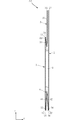
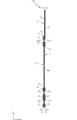
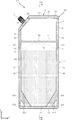
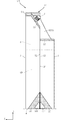
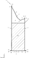
図1は、パウチ容器用包材A1を示す正面図である。図2は、パウチ容器用包材A1を示す要部分解斜視図である。図3は、図1のIII−III線に沿う断面図である。図4は、図1のIV−IV線に沿う断面図である。これらの図において、y方向は、「前後方向」に相当し、z方向は、「上下方向」に相当し、上下方向の上側を「天」側、下側を「底」側と称する。また、x方向を「幅方向」と称する場合がある。また、図1においては、理解の便宜上、シール部5にハッチングを付している。図2は、パウチ容器用包材A1における前方シート1、後方シート2、天ガセットシート3及び底ガセットシート4のそれぞれの形状や相対的な関係を示すものであり、パウチ容器用包材A1の特定の製造手順を示すものではない。
FIG. 1 is a front view showing a packaging material A1 for a pouch container. FIG. 2 is an exploded perspective view of a main part showing the packaging material A1 for a pouch container. FIG. 3 is a cross-sectional view taken along the line III-III of FIG. FIG. 4 is a cross-sectional view taken along the line IV-IV of FIG. In these figures, the y direction corresponds to the "front-back direction", the z direction corresponds to the "vertical direction", the upper side in the vertical direction is referred to as the "top" side, and the lower side is referred to as the "bottom" side. Further, the x direction may be referred to as a "width direction". Further, in FIG. 1, for convenience of understanding, the seal portion 5 is hatched. FIG. 2 shows the shapes and relative relationships of the
前方シート1及び後方シート2は、y方向に重なり合っている。前方シート1及び後方シート2の形状や大きさは特に限定されない。
The
図1及び図2に示すように、前方シート1は、天端縁11、底端縁12及び一対の側端縁13を有する。天端縁11は、z方向の天側に位置する端縁であり、図示された例においては、x方向に沿った直線状である。底端縁12は、z方向の底側に位置する端縁であり、図示された例においては、x方向に沿った直線状である。一対の側端縁13は、z方向において天端縁11と底端縁12との間に位置しており、幅方向であるx方向に離間している。図示された例においては、側端縁13は、z方向に沿った直線状である。
As shown in FIGS. 1 and 2, the
図1及び図2に示すように、後方シート2は、天端縁21、底端縁22、一対の側端縁23及び傾斜端縁24を有する。天端縁21は、z方向の天側に位置する端縁であり、図示された例においては、x方向に沿った直線状である。底端縁22は、z方向の底側に位置する端縁であり、図示された例においては、x方向に沿った直線状である。一対の側端縁23は、z方向において天端縁21と底端縁22との間に位置しており、幅方向であるx方向に離間している。図示された例においては、側端縁23は、z方向に沿った直線状である。また、一方の側端縁23は、他方の側端縁23よりも長さが短い。傾斜端縁24は、天端縁21と一方の側端縁23(短い方の側端縁23)との間に介在しており、x方向及びz方向に対して傾いている。
As shown in FIGS. 1 and 2, the
図示された例においては、底端縁12と底端縁22とが、y方向視において略一致している。また、一対の側端縁13と一対の側端縁23の一部ずつとが、y方向視において略一致している。天端縁11は、天端縁21に対してz方向の下方(底側)に位置している。さらに、天端縁11は、傾斜端縁24に対してz方向の下方(底側)に位置している。
In the illustrated example, the
図1及び図2に示すように、底ガセットシート4は、前方シート1の底端縁12及び後方シート2の底端縁22寄りに位置しており、前方シート1及び後方シート2に挟まれている。底ガセットシート4は、前方部41、後方部42、折返し部43、前方底端縁44、一対の前方側端縁45、後方底端縁46及び一対の後方側端縁47を有する。
As shown in FIGS. 1 and 2, the
前方部41は、前方シート1と対面する部分である。後方部42は、後方シート2と対面する部分である。折返し部43は、前方部41及び後方部42の天端縁同士を繋いでいる。底ガセットシート4は、折返し部43において折られた状態で、前方シート1と後方シート2との間に配置されている。前方底端縁44は、前方部41のz方向の底側に位置する端縁であり、図示された例においては、x方向に沿った直線状である。後方底端縁46は、後方部42のz方向の底側に位置する端縁であり、図示された例においては、x方向に沿った直線状である。図示された例においては、前方底端縁44及び後方底端縁46は、y方向視において底端縁12及び底端縁22と略一致している。
The
一対の前方側端縁45は、z方向において折返し部43と前方底端縁44との間に位置しており、前方部41のx方向に離間した両端縁である。図示された例においては、一対の前方側端縁45のそれぞれは、2つの凹部451を有する。凹部451は、前方側端縁45からx方向内方に凹んだ部位である。凹部451の形状は特に限定されず、たとえば半円形状である。2つの凹部451は、z方向に離間して配置されている。なお、凹部451の個数は特に限定されない。
The pair of front side edge 45s are located between the folded-
一対の後方側端縁47は、z方向において折返し部43と後方底端縁46との間に位置しており、後方部42のx方向に離間した両端縁である。図示された例においては、一対の後方側端縁47のそれぞれは、2つの凹部471を有する。凹部471は、後方側端縁47からx方向内方に凹んだ部位である。凹部471の形状は特に限定されず、たとえば半円形状である。2つの凹部471は、z方向に離間して配置されている。なお、凹部471の個数は特に限定されない。
The pair of rear side edge 47s are located between the folded-
一対の前方側端縁45と一対の後方側端縁47とは、y方向視において略一致している。また、一対の前方側端縁45及び一対の後方側端縁47は、一対の側端縁13の一部ずつ及び一対の側端縁23の一部ずつと、y方向視において略一致している。凹部451と凹部471とは、y方向視において略一致している。
The pair of front side edge 45s and the pair of rear side edge edges 47 substantially coincide with each other in the y-direction view. Further, the pair of
図1及び図2に示すように、天ガセットシート3は、前方シート1の天端縁11及び後方シート2の天端縁21寄りに位置しており、前方シート1及び後方シート2に挟まれている。天ガセットシート3は、前方部31、後方部32、折返し部33、前方天端縁34、一対の前方側端縁35、後方天端縁36、一対の後方側端縁37及び傾斜端縁38を有する。
As shown in FIGS. 1 and 2, the
前方部31は、前方シート1と対面する部分である。後方部32は、後方シート2と対面する部分である。折返し部33は、前方部31及び後方部32の底端縁同士を繋いでいる。天ガセットシート3は、折返し部33において折られた状態で、前方シート1と後方シート2との間に配置されている。前方部31のz方向の長さは、後方部32のz方向の長さよりも短い。言い換えると、後方部32の一部は、前方部31からz方向に延出している。
The
前方天端縁34は、前方部31のz方向の天側に位置する端縁であり、図示された例においては、x方向に沿った直線状である。図示された例においては、前方天端縁34は、y方向視において天端縁11と略一致している。後方天端縁36は、後方部32のz方向の天側に位置する端縁であり、図示された例においては、x方向に沿った直線状である。図示された例においては、後方天端縁36は、y方向視において天端縁21と略一致している。
The front
一対の前方側端縁35は、z方向において折返し部33と前方天端縁34との間に位置しており、前方部31のx方向に離間した両端縁である。図示された例においては、一対の前方側端縁35のそれぞれは、凹部351を有する。凹部351は、前方側端縁35からx方向内方に凹んだ部位である。凹部351の形状は特に限定されず、たとえば半円形状である。なお、凹部351の個数は特に限定されない。
The pair of front side edge 35s are located between the folded-
一対の後方側端縁37は、z方向において折返し部33と後方天端縁36との間に位置しており、後方部32のx方向に離間した両端縁である。また、一方の後方側端縁37は、他方の後方側端縁37よりも長さが短い。傾斜端縁38は、後方天端縁36と一方の後方側端縁37(短い方の後方側端縁37)との間に介在しており、x方向及びz方向に対して傾いている。図示された例においては、後方側端縁37は、y方向視において傾斜端縁24と略重なっている。
The pair of rear side edge 37s are located between the folded-
図示された例においては、一対の後方側端縁37のそれぞれは、凹部371を有する。凹部371は、後方側端縁37からx方向内方に凹んだ部位である。凹部371の形状は特に限定されず、たとえば半円形状である。なお、凹部371の個数は特に限定されない。
In the illustrated example, each of the pair of rear edge 37s has a
一対の前方側端縁35と一対の後方側端縁37とは、y方向視において略一致している。また、一対の前方側端縁35及び一対の後方側端縁37は、一対の側端縁13の一部ずつ及び一対の側端縁23の一部ずつと、y方向視において略一致している。凹部351と凹部371とは、y方向視において略一致している。
The pair of front side edge edges 35 and the pair of rear side edge edges 37 substantially coincide with each other in the y-direction view. Further, the pair of
前方シート1、後方シート2、底ガセットシート4及び天ガセットシート3は、通常、樹脂フィルムから構成される。該樹脂フィルムには、耐衝撃性、耐磨耗性、及び耐熱性等、包装体としての基本的な性能を備えることが要求される。また、後述のシール部5は、通常、ヒートシールにより形成されるので、シートにはヒートシール性も要求される。シートとしては、ベースフィルム層と、ヒートシール性を付与するシーラント層とを有する複層シートが好適であり、高いガスバリア性や遮光性が要求される場合には、ベースフィルム層とシーラント層との間にバリア層を設けることが好適である。なお、ベースフィルム層そのものにバリア性を付与してもよい。この場合は、バリア層をベースフィルム層として用い、バリア層とシーラント層とを有する複層シートとなる。
The
ここで、ベースフィルム層、シーラント層、及びガスバリア層の構成材料を例示する。なお、これら各層の積層は、慣用のラミネート法、例えば、共押出しラミネーション、接着剤によるドライラミネーション、熱接着性層を挟んで熱により接着させる熱ラミネーション等により行うことができる。 Here, the constituent materials of the base film layer, the sealant layer, and the gas barrier layer will be illustrated. Lamination of each of these layers can be performed by a conventional laminating method, for example, coextrusion lamination, dry lamination with an adhesive, thermal lamination in which a heat-adhesive layer is sandwiched and heat-bonded.
ベースフィルム層を構成するフィルムとしては、ポリエステル(ポリエチレンテレフタレート(PET)、ポリエチレンナフタレ−ト(PEN)、ポリブチレンテレフタレート(PBT)、ポリカーボネート(PC)等)、ポリオレフィン(ポリエチレン(PE)、ポリプロピレン(PP)等)、ポリアミド(ナイロン−6、ナイロン−66等)、ポリアクリロニトリル(PAN)、ポリイミド(PI)、ポリ塩化ビニル(PVC)、ポリ塩化ビニリデン(PVDC)、ポリメチルメタクリレート(PMMA)、ポリエーテルスルフォン(PES)等から構成される一層または二層以上の延伸または未延伸フィルムが例示できる。 Examples of the film constituting the base film layer include polyester (polyethylene terephthalate (PET), polyethylene naphthalate (PEN), polybutylene terephthalate (PBT), polycarbonate (PC), etc.), polyolefin (polyethylene (PE), polypropylene ( PP), etc.), Polyethylene (Nylon-6, Nylon-66, etc.), Polyacrylonitrile (PAN), Polyethylene (PI), Polyvinyl Chloride (PVC), Polybutylene Chloride (PVDC), Polymethylmethacrylate (PMMA), Poly Examples thereof include a one-layer or two-layer or more stretched or unstretched film composed of ether sulfone (PES) or the like.
シーラント層を構成するフィルムとしては、低密度ポリエチレン(LDPE)、直鎖状低密度ポリエチレン(LLDPE)、エチレン−プロピレン共重合体(EP)、未延伸ポリプロピレン(CPP)、二軸延伸ナイロン(ON)、エチレン−オレフィン共重合体、エチレン−アクリル酸共重合体(EAA)、エチレン−メタクリル酸共重合体(EMAA)及びエチレン−酢酸ビニル共重合体(EVA)等から構成される一層または二層以上の延伸または未延伸フィルムが例示できる。 Examples of the film constituting the sealant layer include low density polyethylene (LDPE), linear low density polyethylene (LLDPE), ethylene-propylene copolymer (EP), unstretched polypropylene (CPP), and biaxially stretched nylon (ON). , Ethylene-olefin copolymer, ethylene-acrylic acid copolymer (EAA), ethylene-methacrylic acid copolymer (EMAA), ethylene-vinyl acetate copolymer (EVA), etc. Can be exemplified by a stretched or unstretched film of.
ガスバリア層としては、アルミニウム等の金属薄膜、又は塩化ビニリデン(PVDC)、エチレン−ビニルアルコール共重合体(EVOH)等の樹脂フィルム、或いは任意の合成樹脂フィルム(例えば、ベースフィルム層であってもよい)に、アルミニウム、酸化アルミニウムやシリカ等の無機酸化物等を蒸着(又はスパッタリング)したフィルムが例示できる。 The gas barrier layer may be a metal thin film such as aluminum, a resin film such as vinylidene chloride (PVDC) or ethylene-vinyl alcohol copolymer (EVOH), or an arbitrary synthetic resin film (for example, a base film layer). ), An example is a film obtained by depositing (or sputtering) an inorganic oxide such as aluminum, aluminum oxide or silica.
スパウト7は、パウチ容器用包材A1を用いて製造されたパウチ容器包装体において、収容部6に収容された内容物を注出するためのものである。図示された例においては、スパウト7は、後方シート2の傾斜端縁24と天ガセットシート3の後方部32の傾斜端縁38との間に配置されている。
The
シール部5は、前方シート1、後方シート2、底ガセットシート4、天ガセットシート3及びスパウト7から適宜選択された部分同士が接合されたものである。シール部5を形成する手法は限定されず、収容部6を密閉状態とし得る手法であればよく、本実施形態においてはヒートシールが用いられている。図1、図3及び図4に示すように、図示された例においては、シール部5は、一対の前方サイドシール部51、一対の後方サイドシール部52、前方天シール部53、傾斜シール部55、一対のサイドシール部56、前方底シール部57及び後方底シール部58を含む。なお、以降に説明するシール部5をヒートシールによって形成する場合、前方シート1のうち後方シート2、天ガセットシート3及び底ガセットシート4と対面する面、後方シート2のうち前方シート1、天ガセットシート3及び底ガセットシート4と対面する面、天ガセットシート3のうち前方シート1及び後方シート2と対面する面、底ガセットシート4のうち前方シート1及び後方シート2と対面する面が、シーラント層によって構成される。また、シーラント層とは反対側の面が、ベースフィルム層によって構成される。
The seal portion 5 is formed by joining portions appropriately selected from the
一対の前方サイドシール部51は、前方シート1の一対の側端縁13に沿った部分と天ガセットシート3の前方部31の一対の前方側端縁35に沿った部分とが、接合された部分である。一対の後方サイドシール部52は、後方シート2の一対の側端縁23に沿った部分と天ガセットシート3の後方部32の一対の後方側端縁37に沿った部分とが、接合された部分である。なお、図示された例においては、一対の凹部351及び一対の凹部371が形成されていることにより、凹部351及び凹部371を通じて、前方シート1及び後方シート2の一部ずつが接合される。これにより、一対の前方サイドシール部51と一対の後方サイドシール部52とが、部分的に互いに固定された構造となっている。
In the pair of front
一対のサイドシール部56は、前方シート1の一対の側端縁13に沿った部分と後方シート2の一対の側端縁23に沿った部分とのうち、天ガセットシート3及び底ガセットシート4からそれぞれ露出した部分同士が接合された部分である。
The pair of
前方底シール部57は、前方シート1の底端縁12に沿った部分及び一対の側端縁13に沿った部分の一部ずつと、底ガセットシート4の前方部41の前方底端縁44及び一対の前方側端縁45に沿った部分とが、接合された部分である。後方底シール部58は、後方シート2の底端縁22に沿った部分及び一対の側端縁23に沿った部分の一部ずつと、底ガセットシート4の後方部42の後方底端縁46及び一対の後方側端縁47に沿った部分とが、接合された部分である。
The front
なお、図示された例においては、二対の凹部451及び二対の凹部471が形成されていることにより、凹部451及び凹部471を通じて、前方シート1及び後方シート2の一部ずつが接合される。これにより、前方底シール部57と後方底シール部58とが、部分的に互いに固定された構造となっている。また、図示された例においては、前方底シール部57には、一対の未シール部571が設けられている。未シール部571は、ヒートシールが施されていない部位であり、前方シート1と底ガセットシート4の前方部41との間に空気が溜まり得る部位である。未シール部571を設けることにより、前方底シール部57を形成するためのヒートシール工程において、排出しきれなかった空気が意図しない部位に残存し、接合強度を低下させたり、外観を損ねたりすることを抑制することができる。後方底シール部58にも、同様の未シール部(図6の未シール部581)を設けることが好ましい。
In the illustrated example, since the two pairs of
傾斜シール部55は、後方シート2の傾斜端縁24に沿った部分と天ガセットシート3の後方部32の傾斜端縁38に沿った部分とが接合された部位である。また、傾斜シール部55の中央付近においては、後方シート2と天ガセットシート3の後方部32とスパウト7とが接合されている。これにより、スパウト7は、収容部6に通じている。
The
後方シート2の天端縁21に沿った部分と天ガセットシート3の後方部32の後方天端縁36に沿った部分との未接合部分は、後述の収容部6に通じる開口部を構成している。この開口部は、たとえば後述の内容物69を収容部6に充填する工程で利用される。
The unjoined portion between the portion along the
収容部6は、内容物を収容するものであり、図示された例においては、前方シート1、後方シート2、底ガセットシート4及び天ガセットシート3に囲まれた空間である。パウチ容器用包材A1においては、上述の開口部に繋がる部分を除き、シール部5によって密閉されている。
The
パウチ容器用包材A1の製造方法は、何ら限定されず、従来公知の製造方法を適宜採用可能である。たとえば、長尺状の複数の原反シートを長手方向に送りつつ、折返しや重ね合わせ、及びヒートシールや切断を行うことにより、複数のパウチ容器用包材A1を連続的に製造する方法であってもよく、あるいは、1つずつのパウチ容器用包材A1を個別に製造する方法であってもよい。 The manufacturing method of the packaging material A1 for the pouch container is not limited in any way, and a conventionally known manufacturing method can be appropriately adopted. For example, it is a method of continuously manufacturing a plurality of packaging materials A1 for pouch containers by folding, stacking, heat-sealing, and cutting while feeding a plurality of long raw fabric sheets in the longitudinal direction. Alternatively, it may be a method of individually manufacturing the packaging material A1 for each pouch container.
また、パウチ容器用包材A1を用いたパウチ容器包装体の製造においては、たとえば後方シート2の天端縁21と天ガセットシート3の後方天端縁36との間に設けられた開口部から、内容物69を収容部6に充填する。次いで、後方シート2の天端縁21に沿った部分と、天ガセットシート3の後方部32の後方天端縁36に沿った部分とをヒートシールによって接合し、後方天シール部54を形成する。これにより、図5〜図8に示すように、パウチ容器B1と、パウチ容器B1の収容部6に収容された内容物69とを備えるパウチ容器包装体C1が得られる。
Further, in the manufacture of the pouch container package using the pouch container packaging material A1, for example, from the opening provided between the
パウチ容器包装体C1を構成するパウチ容器B1は、シール部5によって収容部6が密閉状態とされている。この密閉された収容部6に内容物69が収容されている。図6及び図7に示すように、底ガセットシート4がz方向の下方に位置する姿勢で、陳列棚等の上面にパウチ容器包装体C1を載置すると、内容物69の自重によって、底ガセットシート4がより平坦な形に広げられる。このように、底ガセットシート4は、パウチ容器包装体C1を自立させることに寄与する。また、図5〜図8に示すように、内容物69が充填されていることにより、前方シート1及び後方シート2は、z方向視において各々が円弧状に膨出し、前方シート1及び後方シート2が楕円形状や円形状に近い形状を呈する。また、図6〜図8に示すように、天ガセットシート3は、前方シート1及び後方シート2が楕円形状や円形状に近い形状を呈することに対応して、前方部31及び後方部32が大きく開かれた形状をなす。このように、天ガセットシート3は、収容部6の容積をより拡大することに寄与する。
In the pouch container B1 constituting the pouch container package C1, the
図6及び図8に示すように、z方向視において後方シート2が円弧形状に膨出した状態となることにより、後方シート2のx方向端部寄りに位置する傾斜シール部55に固定されたスパウト7は、x方向に対して傾いた姿勢となる。すなわち、x方向外方に向かうほどy方向において前方シート1寄りに位置するように傾いている。
As shown in FIGS. 6 and 8, the
次に、パウチ容器包装体C1の作用について説明する。 Next, the operation of the pouch container / packaging body C1 will be described.
本実施形態によれば、パウチ容器包装体C1は、内容物69が充填されていることによって前方シート1及び後方シート2がz方向視において円形状または楕円形状を呈する形状となる。これに伴い、スパウト7は、x方向に対して傾いた姿勢をとる。前方シート1及び後方シート2の形状は、内容物69が収容されている限り、円形状または楕円形状を維持する。このため、スパウト7は、安定して傾いた姿勢をとる。この結果、スパウト7から内容物69を注出する際に、スパウト7の向きが不安定となるおそれが少なく、内容物69をより安定して注出することができる。したがって、パウチ容器包装体C1によれば、天ガセットシート3を備えることによって収容部6の容積を拡大しつつ、内容物を適切に注出することができる。
According to the present embodiment, the pouch container / packaging body C1 has a shape in which the
図8に示すように、スパウト7が斜め方向を向くとともに、パウチ容器B1が全体としてz方向視において円形状または楕円形状を呈することにより、パウチ容器包装体C1の購入者は、円弧形状となった後方シート2に手Hdを沿わせるようにして、パウチ容器包装体C1を把持した状態で、スパウト7から内容物69を安定して適切に注出することが可能である。本実施形態とは異なり、たとえば、スパウト7がx方向に沿った姿勢であると、スパウト7とは反対側に位置する後方サイドシール部52やサイドシール部56を手Hdによって覆うようにパウチ容器包装体C1を把持して注出することが強いられる。この場合、後方サイドシール部52やサイドシール部56によって、購入者の手Hdに痛感が生じるおそれがあり、また、スパウト7の向きも安定しにくい。本実施形態によれば、このような痛感が生じることを回避することが可能であり、また、スパウト7の向きをより安定させることができる。
As shown in FIG. 8, the pouch container B1 has a circular shape or an elliptical shape as a whole in the z-direction while the
また、スパウト7からの注出を断続的に行うと、注出した内容物69の一部が、スパウト7を伝ってパウチ容器B1の外面に付着する場合がある。本実施形態によれば、図7に示すように、天ガセットシート3の前方部31及び後方部32によって緩やかなV字状や凹曲面状の形状部分が構成される。これにより、スパウト7から伝ってきた内容物69を、天ガセットシート3に溜めることが可能であり、パウチ容器B1の前方シート1や後方シート2の外面に内容物69が過大に付着することを抑制することができる。
Further, when the pouring from the
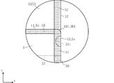
図9は、パウチ容器包装体C1の変形例を示している。なお、同図において、上記実施形態と同一または類似の要素には、上記実施形態と同一の符号を付している。 FIG. 9 shows a modified example of the pouch container package C1. In the figure, the same or similar elements as those in the above embodiment are designated by the same reference numerals as those in the above embodiment.
本変形例においては、前方シート1に曲線部101が設けられており、天ガセットシート3の前方部31に曲線部301が設けられている。曲線部101は、天端縁11と側端縁13との間に介在しており、凸曲線形状である。曲線部301は、前方天端縁34と前方側端縁35との間に介在しており、凸曲線形状である。曲線部101と曲線部301とは、略一致している。
In this modification, the
本変形例によれば、上述したパウチ容器包装体C1の作用効果に加えて、前方サイドシール部51と前方天シール部53との接続部分を緩やかな形状とすることができる。前方サイドシール部51と後方サイドシール部52とは、凹部351及び凹部371が設けられていることにより互いの一部ずつが固定されているが、前方サイドシール部51のz方向天側端部分(前方天シール部53のx方向最外方部分)は、後方サイドシール部52から離間可能な状態である。この部分が、曲線部101及び曲線部301によって緩やかな凸曲線形状であることにより、購入者に痛感が生じることを抑制することが可能である。
According to this modification, in addition to the action and effect of the pouch container / packaging body C1 described above, the connecting portion between the front
本発明に係るパウチ容器包装体は、上述した実施形態に限定されるものではない。本発明に係るパウチ容器包装体の各部の具体的な構成は、種々に設計変更自在である。 The pouch container and packaging body according to the present invention is not limited to the above-described embodiment. The specific configuration of each part of the pouch container and package according to the present invention can be freely redesigned.
A1 :パウチ容器用包材
B1 :パウチ容器
C1 :パウチ容器包装体
1 :前方シート
1A :第1原反シート
2 :後方シート
2A :第2原反シート
3 :天ガセットシート
3A :第3原反シート
4 :底ガセットシート
4A :第4原反シート
5 :シール部
6 :収容部
7 :スパウト
11,11A:天端縁
12 :底端縁
13 :側端縁
21 :天端縁
22 :底端縁
23 :側端縁
24 :傾斜端縁
31,31A:前方部
32 :後方部
33 :折返し部
34,34A:前方天端縁
35 :前方側端縁
36 :後方天端縁
37 :後方側端縁
38 :傾斜端縁
41 :前方部
42 :後方部
43 :折返し部
44 :前方底端縁
45 :前方側端縁
46 :後方底端縁
47 :後方側端縁
51 :前方サイドシール部
52 :後方サイドシール部
53 :前方天シール部
54 :後方天シール部
55 :傾斜シール部
56 :サイドシール部
57 :前方底シール部
58 :後方底シール部
69 :内容物
101,301:曲線部
351,371,451,471:凹部
351A,371A,451A:円孔
571,581:未シール部
Ct :カッター
Hd :手
A1: Packaging material for pouch container B1: Pouch container C1: Pouch container Package 1: Front sheet 1A: 1st original sheet 2: Rear sheet 2A: 2nd original sheet 3: Tengusset sheet 3A: 3rd original sheet Sheet 4: Bottom gusset sheet 4A: 4th original sheet 5: Seal part 6: Containment part 7: Spout 11, 11A: Top edge 12: Bottom edge 13: Side edge 21: Top edge 22: Bottom edge Edge 23: Side end edge 24: Inclined end edge 31, 31A: Front part 32: Rear part 33: Folded part 34, 34A: Front top edge 35: Front side edge 36: Rear top edge 37: Rear side end Edge 38: Inclined end edge 41: Front portion 42: Rear portion 43: Folded portion 44: Front bottom edge edge 45: Front side edge edge 46: Rear bottom edge edge 47: Rear side edge edge 51: Front side seal portion 52: Rear side seal portion 53: Front top seal portion 54: Rear top seal portion 55: Inclined seal portion 56: Side seal portion 57: Front bottom seal portion 58: Rear bottom seal portion 69: Contents 101, 301: Curved portion 351, 371,451,471: Recesses 351A, 371A, 451A: Circular holes 571,581: Unsealed part Ct: Cutter Hd: Hand
Claims (4)
前記前方シート及び前記後方シートの上下方向における天端縁寄りに位置し且つ前記前方シート及び前記後方シートに挟まれた天ガセットシートと、
前記前方シート、前記後方シート及び前記天ガセットシートから選択された部分同士が接合されたシール部と、
前記前方シート、前記後方シート、前記天ガセットシート及び前記シール部によって規定された収容部と、
前記収容部に収容された内容物と、を備え、
前記前方シートは、天端縁及び一対の側端縁を有し、
前記後方シートは、天端縁及び一対の側端縁と、前記天端縁及び一方の前記側端縁の間に介在する傾斜端縁と、を有し、
前記天ガセットシートは、折返し部と、前方天端縁と、前記折返し部及び前記前方天端縁の間に介在する一対の前方側端縁と、後方天端縁と、前記折返し部及び前記後方天端縁との間に介在する一対の後方側端縁と、前記後方天端縁及び一方の前記後方側端縁の間に介在する傾斜端縁と、を有し、
前記シール部は、
前記前方シートの前記一対の側端縁の一部ずつと前記天ガセットシートの前記前方側端縁とが接合された一対の前方サイドシール部と、
前記後方シートの前記一対の側端縁の一部ずつと前記天ガセットシートの前記後方側端縁とが接合された一対の後方サイドシール部と、
前記前方シートの前記天端縁と前記天ガセットシートの前記前方天端縁とが接合された前方天シール部と、
前記後方シートの前記天端縁と前記天ガセットシートの前記後方天端縁とが接合された後方天シール部と、
前記後方シートの前記傾斜端縁と前記天ガセットシートの前記傾斜端縁とが接合された傾斜シール部と、を含み、
前記前方天シール部は、前記後方天シール部よりも上下方向における下方に位置し、
前記後方シートの前記傾斜端縁と前記天ガセットシートの前記傾斜端縁とに挟まれた状態で前記傾斜シール部によって固定され、且つ前記収容部に通じるスパウトを備える、
パウチ容器包装体。 The front and rear seats that overlap in the front-rear direction,
A heavenly gusset sheet located near the top edge in the vertical direction of the front seat and the rear seat and sandwiched between the front seat and the rear seat.
A seal portion in which portions selected from the front sheet, the rear sheet, and the heaven gusset sheet are joined to each other.
The front seat, the rear seat, the heaven gusset seat, and the accommodating portion defined by the seal portion,
With the contents housed in the storage part,
The front sheet has a crown edge and a pair of side edge edges.
The rear sheet has a crown edge and a pair of side edge edges, and an inclined edge edge interposed between the crown edge and one of the side edge edges.
The top gusset sheet includes a folded portion, a front crown edge, a pair of front side edge edges interposed between the folded portion and the front crown edge, a rear crown edge, the folded portion and the rear portion. It has a pair of rear side edges intervening between the crest edge and an inclined edge intervening between the rear crest edge and one of the rear side edges.
The seal portion is
A pair of front side seal portions to which a part of the pair of side edge edges of the front sheet and the front side edge edge of the heaven gusset sheet are joined.
A pair of rear side seal portions to which a part of each of the pair of side edge edges of the rear sheet and the rear side edge edge of the ceiling gusset sheet are joined.
A front top seal portion to which the top edge of the front sheet and the front top edge of the top gusset sheet are joined,
A rear top seal portion to which the top edge of the rear sheet and the rear top edge of the top gusset sheet are joined,
Includes an inclined seal portion to which the inclined edge of the rear sheet and the inclined edge of the heaven gusset sheet are joined.
The front top seal portion is located below the rear top seal portion in the vertical direction.
A spout that is fixed by the inclined seal portion and leads to the accommodating portion while being sandwiched between the inclined edge of the rear seat and the inclined edge of the heaven gusset sheet.
Pouch container packaging.
Priority Applications (1)
| Application Number | Priority Date | Filing Date | Title |
|---|---|---|---|
| JP2019109391A JP2020200090A (en) | 2019-06-12 | 2019-06-12 | Packaging material for pouch container |
Applications Claiming Priority (1)
| Application Number | Priority Date | Filing Date | Title |
|---|---|---|---|
| JP2019109391A JP2020200090A (en) | 2019-06-12 | 2019-06-12 | Packaging material for pouch container |
Publications (1)
| Publication Number | Publication Date |
|---|---|
| JP2020200090A true JP2020200090A (en) | 2020-12-17 |
Family
ID=73742382
Family Applications (1)
| Application Number | Title | Priority Date | Filing Date |
|---|---|---|---|
| JP2019109391A Pending JP2020200090A (en) | 2019-06-12 | 2019-06-12 | Packaging material for pouch container |
Country Status (1)
| Country | Link |
|---|---|
| JP (1) | JP2020200090A (en) |
-
2019
- 2019-06-12 JP JP2019109391A patent/JP2020200090A/en active Pending
Similar Documents
| Publication | Publication Date | Title |
|---|---|---|
| JP5473447B2 (en) | Self-supporting multi-chamber packaging bag and manufacturing method thereof | |
| JP5401369B2 (en) | Self-supporting bag, manufacturing method thereof, and self-supporting bag with contents | |
| JP2012025453A (en) | Packaging bag | |
| JP5640218B2 (en) | Pouch container | |
| JP3815866B2 (en) | Plastic pouch | |
| JPH1179195A (en) | Refill pouches | |
| JP2011031971A (en) | Spout-equipped pouch container | |
| JP2002211589A (en) | Self-supporting bag | |
| WO2015087825A1 (en) | Pouch container and method for manufacturing pouch container | |
| JP2011068367A (en) | Multi-chamber packaging bag and method for manufacturing the same | |
| JP7408943B2 (en) | packaging bag | |
| JP2002128093A (en) | Self-supporting bag | |
| JP4913743B2 (en) | Pouch container with spout and method for producing the same | |
| JP4421277B2 (en) | Packaging bag, method for manufacturing the same, and method for welding members | |
| JP6151474B2 (en) | Pouch container and manufacturing method thereof | |
| JP2020200090A (en) | Packaging material for pouch container | |
| JP7383223B2 (en) | packaging bag | |
| JP5002908B2 (en) | Package | |
| JP5323045B2 (en) | Composite container | |
| JP2004168367A (en) | Independence bag | |
| JP4659964B2 (en) | Self-supporting bag | |
| JP2002019790A (en) | Independence bag | |
| JP6712158B2 (en) | Pouch container and manufacturing method thereof | |
| JP6981833B2 (en) | Manufacturing method of packaging material for pouch containers and pouch container packaging | |
| JP2022051391A (en) | Pouch |