JP2020203473A - Method for manufacturing degassing member for mold - Google Patents
Method for manufacturing degassing member for mold Download PDFInfo
- Publication number
- JP2020203473A JP2020203473A JP2019180187A JP2019180187A JP2020203473A JP 2020203473 A JP2020203473 A JP 2020203473A JP 2019180187 A JP2019180187 A JP 2019180187A JP 2019180187 A JP2019180187 A JP 2019180187A JP 2020203473 A JP2020203473 A JP 2020203473A
- Authority
- JP
- Japan
- Prior art keywords
- annular region
- laser beam
- mold
- region
- degassing
- Prior art date
- Legal status (The legal status is an assumption and is not a legal conclusion. Google has not performed a legal analysis and makes no representation as to the accuracy of the status listed.)
- Granted
Links
Images





Landscapes
- Molds, Cores, And Manufacturing Methods Thereof (AREA)
- Moulds For Moulding Plastics Or The Like (AREA)
- Powder Metallurgy (AREA)
Abstract
【課題】容易に多孔質の構造を形成することができるガス抜き部材の製造方法を提供する。
【解決手段】ガス抜き部材140の製造方法は、敷き詰められた金属粉末Mに対してレーザー光Lを照射して固化することによってガス抜き部材140を製造する。ガス抜き部材140の製造方法は、環状の環状領域Rの端部に沿ってレーザー光Lの中心が移動するようにレーザー光を走査して、環状領域Rよりも内側に、レーザー光Lが照射されない非照射領域Rbを形成する。
【選択図】図11PROBLEM TO BE SOLVED: To provide a method for manufacturing a degassing member capable of easily forming a porous structure.
A method for manufacturing a degassing member 140 is to irradiate a spread metal powder M with a laser beam L to solidify the degassing member 140. In the method of manufacturing the degassing member 140, the laser beam is scanned so that the center of the laser beam L moves along the end of the annular region R, and the laser beam L is irradiated inside the annular region R. A non-irradiated region Rb that is not irradiated is formed.
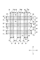
[Selection diagram] FIG. 11
Description
本発明は、ガス抜き部材の製造方法に関する。 The present invention relates to a method for manufacturing a degassing member.
特許文献1記載の金型は、ガスベントを備える。ガスベントによって、キャビティ内のガスをガスベントによって排出している。
The mold described in
しかしながら、特許文献1に記載の金型は、キャビティとガスベントとの接続部分の深さが浅いため、キャビティの外部に排出する気体の量が少なくなる可能性がある。
However, in the mold described in
本発明は上記課題に鑑みてなされたものであり、その目的は材料流通部の外部に排出する気体の排出量を多くすることができるガス抜き部材の製造方法を提供することにある。 The present invention has been made in view of the above problems, and an object of the present invention is to provide a method for manufacturing a degassing member capable of increasing the amount of gas discharged to the outside of a material distribution unit.
本発明に係る金型は、第1金型部材と、第2金型部材と、材料流通部と、ガス抜き部材とを備える。前記材料流通部は、前記第1金型部材と前記第2金型部材との間に形成される。前記材料流通部は、成形品を形成するための材料が流通する。前記ガス抜き部材は、前記材料流通部の内部に残留する気体を前記材料流通部の外部に排出する。前記ガス抜き部材は、第1面と、側面とを有する。前記第1面は、前記材料流通部に対向する。前記側面は、前記第1面に接続する。前記第1面は、流入部を有する。前記流入部は、第1方向に気体が流入可能である。前記流入部には、貫通孔が形成されている。前記第1面または前記側面の少なくとも一方に、前記流入部から流入した気体を第2方向に排出可能である排出部を有する。前記第1方向と前記第2方向とは交差している。 The mold according to the present invention includes a first mold member, a second mold member, a material distribution unit, and a degassing member. The material distribution section is formed between the first mold member and the second mold member. In the material distribution section, materials for forming a molded product are distributed. The degassing member discharges the gas remaining inside the material distribution unit to the outside of the material distribution unit. The degassing member has a first surface and a side surface. The first surface faces the material distribution section. The side surface is connected to the first surface. The first surface has an inflow portion. Gas can flow into the inflow portion in the first direction. A through hole is formed in the inflow portion. At least one of the first surface or the side surface has a discharge portion capable of discharging the gas flowing in from the inflow portion in the second direction. The first direction and the second direction intersect.
ある実施形態において、前記ガス抜き部材は、第2面をさらに有する。前記第2面は、前記側面に接続する。前記第2面は、前記第1面に対向する。 In certain embodiments, the degassing member further comprises a second surface. The second surface is connected to the side surface. The second surface faces the first surface.
ある実施形態において、前記貫通孔は、前記第1面から前記第2面に向かう方向に延びる。 In certain embodiments, the through hole extends in a direction from the first surface to the second surface.
ある実施形態において、前記材料流通部には、前記成形品の材料が充填される。前記流入部は、前記成形品の材料が流入不可である。 In certain embodiments, the material distribution section is filled with the material of the article. The material of the molded product cannot flow into the inflow portion.
ある実施形態において、前記材料流通部には、前記成形品の材料が充填される。前記材料流通部に充填される前記成形品の材料の流れる方向と、前記排出部から気体が流れる方向とのなす角度は、90度以下である。 In certain embodiments, the material distribution section is filled with the material of the article. The angle between the flow direction of the material of the molded product filled in the material distribution section and the flow direction of the gas from the discharge section is 90 degrees or less.
ある実施形態において、前記流入部と前記排出部との間に気体が流通する流通空間が形成される。 In certain embodiments, a flow space through which gas flows is formed between the inflow section and the discharge section.
ある実施形態において、前記金型は、排出経路をさらに備える。前記排出経路は、気体を前記第1金型部材の外部または前記第2金型部材の外部へ排出する。前記排出部は前記排出経路に連絡する。 In certain embodiments, the mold further comprises a discharge path. The discharge path discharges the gas to the outside of the first mold member or the outside of the second mold member. The discharge unit communicates with the discharge route.
ある実施形態において、前記排出経路は、前記第1金型部材と前記第2金型部材との間に形成される。 In certain embodiments, the discharge path is formed between the first mold member and the second mold member.
ある実施形態において、前記成形品の材料は、樹脂および金属の少なくとも一方である。 In certain embodiments, the material of the article is at least one of a resin and a metal.
本発明に係るガス抜き部材は、金型に取り付けられる。前記ガス抜き部材は、第1面と、側面と、第2面とを有する。前記側面は、前記第1面に接続する。前記第2面は、前記側面に接続する。前記第2面は、前記第1面に対向する。前記第1面は、流入部を有する。前記流入部は、第1方向に気体が流入可能である。前記流入部には、貫通孔が形成されている。前記第1面または前記側面の少なくとも一方に、前記流入部から流入した気体を第2方向に排出可能である排出部を有する。前記第1方向と前記第2方向とは交差している。 The degassing member according to the present invention is attached to a mold. The degassing member has a first surface, a side surface, and a second surface. The side surface is connected to the first surface. The second surface is connected to the side surface. The second surface faces the first surface. The first surface has an inflow portion. Gas can flow into the inflow portion in the first direction. A through hole is formed in the inflow portion. At least one of the first surface or the side surface has a discharge portion capable of discharging the gas flowing in from the inflow portion in the second direction. The first direction and the second direction intersect.
ある実施形態において、前記流入部と前記排出部との間に気体が流通する流通空間が形成される。 In certain embodiments, a flow space through which gas flows is formed between the inflow section and the discharge section.
ある実施形態において、前記貫通孔は、前記第1面から前記第2面に向かう方向に延びる。 In certain embodiments, the through hole extends in a direction from the first surface to the second surface.
本発明に係るガス抜き部材の製造方法は、敷き詰められた金属粉末に対してレーザー光を照射して固化することによってガス抜き部材を製造する。前記ガス抜き部材の製造方法は、環状の環状領域の端部に沿って前記レーザー光の中心が移動するように前記レーザー光を走査して、前記環状領域よりも内側に、前記レーザー光が照射されない非照射領域を形成する。 In the method for manufacturing a degassing member according to the present invention, the degassing member is manufactured by irradiating the spread metal powder with a laser beam and solidifying it. In the method for manufacturing the degassing member, the laser light is scanned so that the center of the laser light moves along the end of the annular region, and the laser light is irradiated inside the annular region. Form a non-irradiated area that is not.
ある実施形態において、前記環状領域は、第1辺と、第2辺とを有する。前記第1辺は、所定方向に延びる。前記第2辺は、前記所定方向と交差する交差方向に延びる。前記ガス抜き部材の製造方法は、第1走査工程と、第2走査工程とを包含する。前記第1走査工程において、前記第1辺に沿って前記レーザー光の中心が移動する。前記第2走査工程において、前記第2辺に沿って前記レーザー光の中心が移動する。前記第1辺の長さは、前記レーザー光のスポット径よりも長い。前記第2辺の長さは、前記レーザー光のスポット径よりも長い。 In certain embodiments, the annular region has a first side and a second side. The first side extends in a predetermined direction. The second side extends in an intersecting direction intersecting the predetermined direction. The method for manufacturing the degassing member includes a first scanning step and a second scanning step. In the first scanning step, the center of the laser beam moves along the first side. In the second scanning step, the center of the laser beam moves along the second side. The length of the first side is longer than the spot diameter of the laser beam. The length of the second side is longer than the spot diameter of the laser beam.
ある実施形態において、前記環状領域は複数である。複数の前記環状領域は、第1環状領域と、第2環状領域とを含む。前記第1環状領域は、前記所定方向に延びる。前記第2環状領域は、前記交差方向に延びる。 In certain embodiments, the annular region is plural. The plurality of annular regions include a first annular region and a second annular region. The first annular region extends in the predetermined direction. The second annular region extends in the crossing direction.
ある実施形態において、前記環状領域は複数である。隣接する前記環状領域の間隔は、前記レーザー光のスポット径よりも長い。 In certain embodiments, the annular region is plural. The distance between the adjacent annular regions is longer than the spot diameter of the laser beam.
本発明に係る金型によれば、材料流通部の外部に排出する気体の排出量を多くすることができる。 According to the mold according to the present invention, the amount of gas discharged to the outside of the material distribution unit can be increased.
以下、本発明の実施形態について、図面を参照しながら説明する。なお、図中、同一または相当部分については同一の参照符号を付して説明を繰り返さない。 Hereinafter, embodiments of the present invention will be described with reference to the drawings. In the drawings, the same or corresponding parts are designated by the same reference numerals and the description is not repeated.
[実施形態1]
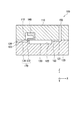
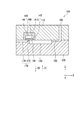
図1および図2を参照して、本発明の実施形態1に係る金型100について説明する。図1は、本発明の実施形態1に係る金型100の模式的な断面図である。図2は、本発明の実施形態1に係る金型100の模式的な分解断面図である。図1において、X軸およびY軸は互いに直交し水平面に平行であり、Z軸は鉛直方向に平行である。
[Embodiment 1]
The
図1および図2に示すように、金型100は、金型部材110と、金型部材120と、キャビティ130と、ガス抜き部材140と、スプール150と、ランナー160と、ベント170とを備える。なお、金型部材110は、「第1金型部材」の一例に相当する。金型部材120は、「第2金型部材」の一例に相当する。キャビティ130は、「材料流通部」の一例に相当する。
As shown in FIGS. 1 and 2, the
金型100は、射出成形用の金型である。
The
金型部材110は、金型部材120の上方に位置する。金型部材110と金型部材120とは、互いに対向する。金型部材110は、例えば、金属製である。図2に示すように、金型部材110には、凹部112が設けられている。本実施形態では、凹部112は、円柱状である。なお、凹部112は、金型部材120に設けられてもよい。
The
金型部材120は、金型部材110の下方に位置する。金型部材120は、例えば、金属製である。図2に示すように、金型部材120には、凹部121と、凹部122と、凹部123と、凹部124とが設けられている。なお、凹部121と、凹部122と、凹部123と、凹部124とは、金型部材110に設けられてもよい。
The
キャビティ130は、金型部材110と金型部材120との間に形成される。具体的には、キャビティ130は、金型部材110の下面と凹部122とによって形成される空間である。キャビティ130は、成形品を形成するための空間である。キャビティ130は、成形品の形状に対応する。本実施形態では、成形品は、断面視において、矩形状を有する。キャビティ130には、成形品の材料が充填される。成形品の材料は、例えば、樹脂である。
The
ガス抜き部材140は、キャビティ130の内部に残留する気体をキャビティ130の外部に排出する。ガス抜き部材140は、凹部112に取り付けられる。例えば、ガス抜き部材140は、凹部112に圧入されることによって、凹部112に取り付けられる。あるいは、ガス抜き部材140は、凹部112に固定具によって、凹部112に取り付けられてもよい。固定具は、例えば、ネジである。ガス抜き部材140の詳細については、図2および図3を参照して後述する。
The degassing
スプール150は、金型部材110に形成されている。スプール150は、Z軸方向に沿って延びる。スプール150は、射出成形機から射出された樹脂が最初に流れ込む通路である。
The
ランナー160は、スプール150に接続している。ランナー160は、X軸方向に沿って延びる。ランナー160は、金型部材110と金型部材120との間に形成される。具体的には、ランナー160は、金型部材110の下面と凹部121とによって形成される空間である。
The
ベント170は、接続経路172と排出経路174とを有する。ベント170は、キャビティ130に残留する気体を金型100の外部に排出する。ベント170は、金型部材110と金型部材120との間に形成される。すなわち、接続経路172と排出経路174とは、金型部材110と金型部材120との間に形成される。具体的には、ベント170は、金型部材110の下面と凹部123および凹部124とによって形成される空間である。
The
接続経路172の+X方向側の端部は、キャビティ130の−X方向側の端部に連絡している。接続経路172の−X方向側の端部は、排出経路174の+X方向側の端部に連絡している。接続経路172の深さ(Z軸方向に沿った長さ)は、例えば、0.01mm以上0.02mm以下である。
The end of the
排出経路174の−X方向側の端部は、金型100の外部に連絡している。排出経路174の深さは、接続経路172の深さよりも深い。排出経路174の深さは、例えば、0.2mmmである。したがって、接続経路172に比べて、排出経路174の方が気体が流れやすい。
The end of the
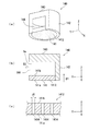
次に、図3(a)〜図3(c)を参照して、ガス抜き部材140についてさらに説明する。図3(a)は、ガス抜き部材140の模式的な斜視図である。図3(b)は、ガス抜き部材140の断面図である。図3(c)は、流入部1412の拡大断面図である。
Next, the degassing
図3(a)に示すように、ガス抜き部材140は、第1面141と、側面142と、第2面143とを有する。
As shown in FIG. 3A, the degassing
第1面141は、例えば、XY平面に平行である。なお、第1面141は、例えば、XY平面に対して傾斜していてもよい。第1面141は、ガス抜き部材140の下面を構成する。第1面141は、−Z方向側から視た平面視において、円の一部を切り欠いた形状を有している。
The
側面142は、第1面141に接続する。側面142は、ガス抜き部材140の側面を構成する。側面142は、湾曲している。なお、側面142は、湾曲していなくもよい。例えば、側面142は、平坦状であってもよい。
The
第2面143は、側面142に接続する。第2面143は、第1面141に対向する。第2面143は、例えば、XY平面に平行である。なお、第2面143は、例えば、XY平面に対して傾斜していてもよい。第2面143は、ガス抜き部材140の上面を構成する。第2面143は、+Z方向側から視た平面視において、円の一部を切り欠いた形状を有している。
The
第1面141は、下面141aと、上面141bとを有する。第1面141は、流入部1412を有する。流入部1412は、第1方向D1に気体が流入可能である。第1方向D1は、Z軸方向に平行である。したがって、流入部1412は、上方向に気体が流入可能である。流入部1412は、多孔質の部材である。したがって、流入部1412には、複数の貫通孔1414が形成されている。
The
複数の貫通孔1414の各々は、流入部1412を貫通する。複数の貫通孔1414の各々は、下面141aから上面141bに貫通する。貫通孔1414は、第1面141から第2面143に向かう方向に延びる。流入部1412は、成形品の材料が流入不可である。本実施形態では、流入部1412は、樹脂が流入不可である。なお、貫通孔1414は、下面141aから上面141bに貫通している限り、どのような形状でも構わない。例えば、球状の孔が不規則に連なることによって、下面141aから上面141bに貫通していてもよい。あるいは、貫通孔1414は、下面141aから上面141bに貫通するスリットであってもよい。
Each of the plurality of through
側面142は、排出部144を有する。排出部144は、開口である。排出部144は、流入部1412から流入した気体を第2方向D2に排出可能である。第2方向D2は、Y軸方向に平行である。したがって、排出部144は、流入部1412から流入した気体を横方向に排出可能である。
The
第1方向D1は、Z軸方向に平行である。第2方向D2は、Y軸方向に平行である。したがって、第1方向D1と第2方向D2とは交差している。 The first direction D1 is parallel to the Z-axis direction. The second direction D2 is parallel to the Y-axis direction. Therefore, the first direction D1 and the second direction D2 intersect.
流入部1412と、排出部144との間に気体が流通する流通空間Saが形成される。流通空間Saは、第1面141の上面と、側面142の内周面と、第2面143の下面とによって規定される空間である。
A distribution space Sa through which gas flows is formed between the
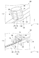
図4(a)および図4(b)を参照して、キャビティ130に残留している気体の排出について説明する。図4(a)は、金型100の模式的な斜視図である。図4(b)は、金型100の模式的な断面図である。なお、図4(a)および図4(b)では、図面の簡略化のため、金型部材110は省略している。また、図4(b)では、理解を容易にするために、断面を示すハッチングは省略している。図4(b)において、方向D3は、キャビティ130に充填される成形品の材料の流れる方向を示す。すなわち、方向D3は、樹脂が流れる方向を示す。また、図4(b)において、方向D4は、排出部144から気体が流れる方向を示す。また、図4(b)において、白抜矢印は、気体の流れる方向を示す。
The discharge of the gas remaining in the
図4(a)および図4(b)に示すように、第1面141は、キャビティ130に対向している。詳しくは、流入部1412は、キャビティ130に対向している。流通空間Saと排出経路174との間には、連絡空間Sbが形成される。連絡空間Sbは、流通空間Saと排出経路174とを連絡する。連絡空間Sbは、ガス抜き部材140と金型部材110とによって規定される空間である。したがって、排出部144は、連絡空間Sbを介して排出経路174に連絡している。
As shown in FIGS. 4 (a) and 4 (b), the
図4(b)に示すように、キャビティ130に樹脂が充填されると、方向D3に向けて樹脂が流れる。方向D3に向けて樹脂が流れると、キャビティ130内に溜まっている気体が方向D3に押し出される。図3(c)を参照して説明したように、流入部1412の複数の貫通孔1414が形成されている。したがって、押し出された気体は、流入部1412の複数の貫通孔1414(図3(c)参照)を通って、第1方向D1(上方)へと流入する。そして、流入部1412から流入した気体は、流通空間Saを流通し、排出部144から第2方向D2へと排出される。排出部144から排出された気体は、連絡空間Sbを通って、排出経路174に流入する。そして、排出経路174に流入した気体は、排出経路174を通って、金型部材110の外部および金型部材120の外部に排出される。このように、キャビティ130内に溜まっている気体は、流入部1412、流通空間Sa、連絡空間Sb、および排出経路174を通って、金型100の外部へと排出される。
As shown in FIG. 4B, when the
また、キャビティ130に充填される成形品の材料の流れる方向D3と、排出部144から気体が流れる方向D4とのなす角度は、90度以下である。本実施形態では、方向D3と方向D4とはY軸方向に沿っている。したがって、方向D3と方向D4とのなす角度は0度である。すなわち、成形品の材料と気体とは、同じ方向に向かって流れている。
Further, the angle formed by the flow direction D3 of the material of the molded product filled in the
以上、図1〜図4を参照して説明したように、ガス抜き部材140は、第1面141と、側面142とを有する。第1面141は、第1方向D1に気体が流入可能である流入部1412を有する。流入部1412には、貫通孔1414が形成されている。側面142は、排出部144を有する。排出部144は、流入部1412から流入した気体を第2方向D2に排出可能である。したがって、貫通孔1414から、材料流通部(キャビティ130)の外部に排出する気体の排出量を多くすることができる。また、第1方向D1と第2方向D2とは交差している。したがって、流入部1412から流入した空気を、排出部144から所望の箇所に排出されるように空気を導くことができる。
As described above with reference to FIGS. 1 to 4, the degassing
また、流入部1412は、成形品の材料が流入不可である。したがって、成形品の材料が流入部1412を介して、キャビティ130の外部に流出することを抑制することができる。
Further, the material of the molded product cannot flow into the
また、キャビティ130に充填される成形品の材料の流れる方向D3と、排出部144から気体が流れる方向D4とのなす角度は、90度以下である。したがって、排出部144から効率良く気体を排出することができる。
Further, the angle formed by the flow direction D3 of the material of the molded product filled in the
また、流入部1412と排出部144との間に気体が流通する流通空間Saが形成される。したがって、流入部1412から流入した空気に大きな圧力がかからない。その結果、排出部144から効率良く気体を排出することができる。
Further, a distribution space Sa through which gas flows is formed between the
また、金型100は、気体を金型部材110の外部または金型部材120の外部へ排出する排出経路174を備える。排出部144は排出経路174に連絡する。したがって、流入部1412から流入した空気を、排出部144から排出し、排出経路174を介して金型部材110の外部または金型部材120の外部へ排出することができる。
Further, the
また、排出経路174は、金型部材110と金型部材120との間に形成される。したがって、金型部材110と金型部材120との少なくとも一方を削ることによって、排出経路174を設けることができる。その結果、金型100の加工が容易となる。
Further, the
[実施形態2]
なお、実施形態1に係る金型100では、排出部144は横向きに気体を排出していたが、排出部144は下向きに気体を排出してもよい。
[Embodiment 2]
In the
図5を参照して、本発明の実施形態2に係る金型100について説明する。図5は、本発明の実施形態2に係る金型100の模式的な断面図である。
The
図5に示すように、ガス抜き部材140は、第1面141と、側面142と、第2面143とを有する。第1面141は、−Z方向側から視た平面視において、円状である。側面142は、ガス抜き部材140の側方の全てを覆う。第2面143は、+Z方向側から視た平面視において、円状である。
As shown in FIG. 5, the degassing
第1面141は、流入部1412と、排出部144とを有する。排出部144は、流入部1412から流入した気体を第2方向D2に排出する。排出部144は、排出経路174と対向する。排出部144は、排出経路174と連絡する。したがって、排出部144から排出された気体は、排出経路174を介して、金型100の外部へ排出される。
The
図5を参照して説明したように、流入部1412と、排出部144とを有する。本実施形態でも、実施形態1と同様に、貫通孔1414から、キャビティ130の外部に排出する気体の排出量を多くすることができる。また、流入部1412から流入した空気を、排出部144から所望の箇所に排出されるように空気を導くことができる。
As described with reference to FIG. 5, it has an
[実施形態3]
なお、実施形態1および実施形態2に係る金型100では、排出部144は、排出経路174に気体を排出していたが、排出部144は、排出経路174とは異なる排出経路174に気体を排出してもよい。
[Embodiment 3]
In the
図6を参照して、本発明の実施形態3に係る金型100について説明する。図6は、本発明の実施形態3に係る金型100の模式的な断面図である。
The
図6に示すように、金型100は、追加排出経路176をさらに有する。追加排出経路176は、金型部材110に形成される。追加排出経路176は、X軸方向に沿って延びる孔である。追加排出経路176の+X方向側の端部は、排出部144に連絡している。排出部144は、流入部1412から流入した気体を第2方向D2に排出する。第2方向D2は、X軸に対して+Z方向側に傾斜している。したがって、排出部144から排出された気体は、追加排出経路176を介して、金型100の外部へ排出される。
As shown in FIG. 6, the
本実施形態でも、実施形態1および実施形態2と同様に、貫通孔1414から、キャビティ130の外部に排出する気体の排出量を多くすることができる。また、流入部1412から流入した空気を、排出部144から所望の箇所に排出されるように空気を導くことができる。
Also in the present embodiment, as in the first and second embodiments, the amount of gas discharged from the through
[実施形態4]
なお、実施形態1〜実施形態3に係る金型100では、排出部144は、開口であったが、排出部144は開口ではなく、排出部144に貫通孔が形成されていてもよい。
[Embodiment 4]
In the
図7を参照して、本発明の実施形態4に係る金型100について説明する。図7は、本発明の実施形態4に係る金型100の模式的な断面図である。
The
図7に示すように、第1面141は、流入部1412と、排出部144とを有する。流入部1412は、第1面141のうち、+X方向側に位置する。排出部144は、第1面141のうち、−X方向側に位置する。排出部144は、流入部1412と同様に貫通孔が設けられている。したがって、排出部144は、貫通孔を介して気体を排出経路174に排出することができる。
As shown in FIG. 7, the
本実施形態でも、実施形態1〜実施形態3と同様に、貫通孔1414から、キャビティ130の外部に排出する気体の排出量を多くすることができる。また、流入部1412から流入した空気を、排出部144から所望の箇所に排出されるように空気を導くことができる。
Also in this embodiment, as in the first to third embodiments, the amount of gas discharged from the through
[実施形態5]
なお、実施形態1〜実施形態4に係る金型100では、ガス抜き部材140は、第2面143を有していたが、ガス抜き部材140は、第2面143を有していなくてもよい。
[Embodiment 5]
In the
図8を参照して、本発明の実施形態5に係る金型100について説明する。図8は、本発明の実施形態5に係る金型100の模式的な断面図である。
The
図8に示すように、ガス抜き部材140は、第1面141と、側面142とを有する。凹部112は、面112aを有する。本実施形態では、面112aと側面142とによって、排出部144が形成される。したがって、排出部144は、流入部1412から流入した気体を排出することができる。
As shown in FIG. 8, the degassing
本実施形態でも、実施形態1〜実施形態4と同様に、貫通孔1414から、キャビティ130の外部に排出する気体の排出量を多くすることができる。また、流入部1412から流入した空気を、排出部144から所望の箇所に排出されるように空気を導くことができる。
Also in this embodiment, as in the first to fourth embodiments, the amount of gas discharged from the through
[実施形態6]
なお、実施形態1〜実施形態5に係る金型100では、ガス抜き部材140は、キャビティ130の内部に残留する気体をキャビティ130の外部に排出していたが、本発明はこれに限定されない。例えば、ガス抜き部材140は、ランナー160に設けられていてもよい。
[Embodiment 6]
In the
図9を参照して、本発明の実施形態6に係る金型100について説明する。図9は、本発明の実施形態6に係る金型100の模式的な断面図である。実施形態1〜実施形態5と重複する部分は、説明を省略する。
The
図9に示すように、金型100は、金型部材110と、金型部材120と、金型部材180と、キャビティ130と、ガス抜き部材140aと、ガス抜き部材140bと、スプール150と、ランナー160aと、ランナー160bと、ベント170aと、ベント170bと、二次スプール190aと、二次スプール190bとを備える。ランナー160aと、ランナー160bとは、「材料流通部」の一例に相当する。
As shown in FIG. 9, the
金型部材180は、金型部材120の下方に位置する。金型部材120は、例えば、金属製である。金型部材180には、凹部182が設けられている。
The
キャビティ130は、金型部材120と金型部材180との間に形成される。具体的には、キャビティ130は、金型部材120の下面と凹部182とによって形成される空間である。
The
ランナー160aおよびランナー160bは、スプール150に接続している。ランナー160aおよびランナー160bは、X軸方向に沿って延びる。具体的には、ランナー160aは、スプール150の端部から−X側方向に延びている。ランナー160bは、スプール150の端部から+X側方向に延びている。したがって、スプール150から供給された樹脂は、ランナー160aとランナー160bとに分岐して流れる。
The
二次スプール190aおよび二次スプール190bは、金型部材120に形成されている。二次スプール190aおよび二次スプール190bは、Z軸方向に沿って延びる。二次スプール190aの一方の端部はランナー160aに接続している。二次スプール190aの他方の端部はキャビティ130に接続している。したがって、ランナー160aに流れた樹脂は、二次スプール190aを介してキャビティ130に流れる。同様に、二次スプール190bの一方の端部はランナー160bに接続している。二次スプール190bの他方の端部はキャビティ130に接続している。したがって、ランナー160bに流れた樹脂は、二次スプール190bを介してキャビティ130に流れる。
The
本実施形態では、ランナー160aにガス抜き部材140aが設けられる。したがって、ランナー160aに残留している気体を効率良く排出することができる。同様に、ランナー160bにガス抜き部材140bが設けられる。したがって、ランナー160bに残留している気体を効率良く排出することができる。
In the present embodiment, the
なお、キャビティ130にもガス抜き部材140を設けてもよい。この場合、金型部材120が、「第1金型部材」の一例に相当し、金型部材180が、「第2金型部材」の一例に相当する。
The
[実施形態7]
図10(a)〜図10(e)を参照して、本発明の実施形態7に係るガス抜き部材140の製造方法について説明する。図10(a)〜図10(e)は、本発明の実施形態7に係るガス抜き部材140の製造方法を示す模式図である。
[Embodiment 7]
A method for manufacturing the
ガス抜き部材140は、例えば、金属3Dプリンター200で製造される。金属3Dプリンター200は、土台210と、リコータ−220とを備える。
The degassing
まず、図10(a)に示すように、リコータ−220が、土台210の上に金属粉末Mをまきながら、平らになるようにならして金属粉末Mを土台210の上に敷き詰める。 First, as shown in FIG. 10A, the recoater-220 spreads the metal powder M on the base 210 while sprinkling the metal powder M on the base 210 so that the metal powder M is flattened.
次に、図10(b)に示すように、金属粉末Mにレーザー光Lを照射して、金属粉末Mを固化(焼結)する。レーザー光Lは、例えば、Ybレーザーである。図10(b)において、照射領域Raは、レーザー光Lが照射される領域を示す。非照射領域Rbは、レーザー光Lが照射されない領域を示す。図10(b)において、金属粉末Mが固化された箇所をハッチングで示している。図10(b)に示すように、非照射領域Rbは、所定の間隔を開けて設けられる。したがって、所定の間隔をあけて、金属粉末Mは固化される。 Next, as shown in FIG. 10B, the metal powder M is irradiated with the laser beam L to solidify (sinter) the metal powder M. The laser beam L is, for example, a Yb laser. In FIG. 10B, the irradiation region Ra indicates a region to which the laser beam L is irradiated. The non-irradiated region Rb indicates a region where the laser beam L is not irradiated. In FIG. 10B, the portion where the metal powder M is solidified is shown by hatching. As shown in FIG. 10B, the non-irradiated regions Rb are provided at predetermined intervals. Therefore, the metal powder M is solidified at predetermined intervals.
次に、図10(c)に示すように、再び、リコータ−220が、土台210の上に金属粉末Mをまきながら、平らになるようにならして金属粉末Mを積層する。
Next, as shown in FIG. 10 (c), the recoater-220 again sprinkles the metal powder M on the
次に、図10(d)に示すように、金属粉末Mにレーザー光Lを照射して、金属粉末Mを固化(焼結)する。図10(d)において、照射領域Raは、図10(b)に示す照射領域Raと同じ位置である。したがって、レーザー光Lを照射する箇所は、図10(b)においてレーザー光Lを照射した箇所と同じ箇所である。 Next, as shown in FIG. 10D, the metal powder M is irradiated with the laser beam L to solidify (sinter) the metal powder M. In FIG. 10D, the irradiation region Ra is at the same position as the irradiation region Ra shown in FIG. 10B. Therefore, the portion irradiated with the laser beam L is the same location as the portion irradiated with the laser beam L in FIG. 10B.
図10(c)に示す工程と、図10(d)に示す工程とを繰り返すことによって、図10(e)に示すように、貫通孔1414を形成することができる。
By repeating the step shown in FIG. 10 (c) and the step shown in FIG. 10 (d), the through
図11〜図13を参照して、本発明の実施形態5に係るガス抜き部材140の製造方法についてさらに説明する。図11〜図13は、本発明の実施形態7に係るガス抜き部材140の製造方法を示す模式図である。
The method for manufacturing the
まず、図11を参照して、レーザー光Lの軌跡について説明する。図11において、軌跡A、軌跡B、軌跡C、軌跡D、軌跡Eおよび軌跡Fは、レーザー光の軌跡を示す。 First, the trajectory of the laser beam L will be described with reference to FIG. In FIG. 11, the locus A, the locus B, the locus C, the locus D, the locus E, and the locus F indicate the loci of the laser light.
図11において、環状領域RX1、環状領域RX2、環状領域RX3を、右斜め上がりハッチングで示している。また、環状領域RY1、環状領域RY2および環状領域RY3と、右斜め下がりハッチングで示している。なお、環状領域RX1、環状領域RX2および環状領域RX3は、「第1環状領域」の一例に相当する。環状領域RY1、環状領域RY2および環状領域RY3は、「第2環状領域」の一例に相当する。本明細書において、環状領域RX1、環状領域RX2、環状領域RX3、環状領域RY1、環状領域RY2および環状領域RY3を、環状領域Rと総称する場合がある。 In FIG. 11, the annular region RX1, the annular region RX2, and the annular region RX3 are shown by hatching diagonally upward to the right. Further, the annular region RY1, the annular region RY2, and the annular region RY3 are shown by hatching diagonally downward to the right. The annular region RX1, the annular region RX2, and the annular region RX3 correspond to an example of the “first annular region”. The annular region RY1, the annular region RY2, and the annular region RY3 correspond to an example of the “second annular region”. In the present specification, the annular region RX1, the annular region RX2, the annular region RX3, the annular region RY1, the annular region RY2 and the annular region RY3 may be collectively referred to as the annular region R.
図11に示すように、環状領域RX1は矩形状である。環状領域RX1のY軸方向に沿った長さは、環状領域RX1のX軸方向に沿った長さよりも長い。したがって、環状領域RX1は、Y軸方向に延びている。すなわち、環状領域RX1は、縦長の領域である。具体的には、環状領域RX1は、辺S1、辺S2、辺S3および辺S4で囲まれた領域である。環状領域RX1は、頂点A1、頂点A2、頂点A3、頂点A4、辺S1、辺S2、辺S3および辺S4を有する。辺S1は、頂点A1および頂点A2を結ぶ線である。辺S2は、頂点A2および頂点A3を結ぶ線である。辺S3は、頂点A3および頂点A4を結ぶ線である。辺S4は、頂点A4および頂点A1を結ぶ線である。辺S1および辺S3は、Y軸方向に沿って延びている。辺S2および辺S4は、X軸に沿って延びている。なお、辺S1および辺S3は、「第1辺」の一例に相当する。辺S2および辺S4は、「第2辺」の一例に相当する。Y軸方向は、「所定方向」の一例に相当する。X軸方向は、「交差方向」の一例に相当する。所定方向と交差方向とは交差している。 As shown in FIG. 11, the annular region RX1 has a rectangular shape. The length of the annular region RX1 along the Y-axis direction is longer than the length of the annular region RX1 along the X-axis direction. Therefore, the annular region RX1 extends in the Y-axis direction. That is, the annular region RX1 is a vertically long region. Specifically, the annular region RX1 is a region surrounded by sides S1, side S2, side S3, and side S4. The annular region RX1 has a vertex A1, a vertex A2, a vertex A3, a vertex A4, a side S1, a side S2, a side S3, and a side S4. The side S1 is a line connecting the vertices A1 and the vertices A2. The side S2 is a line connecting the vertices A2 and the vertices A3. The side S3 is a line connecting the vertices A3 and the vertices A4. The side S4 is a line connecting the vertices A4 and the vertices A1. Sides S1 and S3 extend along the Y-axis direction. Sides S2 and S4 extend along the X axis. The side S1 and the side S3 correspond to an example of the "first side". The side S2 and the side S4 correspond to an example of the "second side". The Y-axis direction corresponds to an example of a "predetermined direction". The X-axis direction corresponds to an example of the "intersection direction". The predetermined direction and the crossing direction intersect.
本実施形態では、辺S1と辺S2とのなす角度は、90度である。辺S2と辺S3とのなす角度は、90度である。辺S3と辺S4とのなす角度は、90度である。辺S4と辺S1とのなす角度は、90度である。 In the present embodiment, the angle formed by the side S1 and the side S2 is 90 degrees. The angle between the side S2 and the side S3 is 90 degrees. The angle between the side S3 and the side S4 is 90 degrees. The angle formed by the side S4 and the side S1 is 90 degrees.
本実施形態に係るガス抜き部材140の製造方法では、環状領域RX1の端部に沿ってレーザー光Lの中心が移動するようにレーザー光Lを走査する。本実施形態に係るガス抜き部材140の製造方法は、第1走査工程と、第2走査工程とを包含する。第1走査工程において、第1辺に沿って、レーザー光の中心が移動する。第2走査工程において、第2辺に沿って、レーザー光の中心が移動する。具体的には、レーザー光Lの中心が、軌跡Aに沿って移動するようにレーザー光Lを走査する。より詳しくは、頂点A1を始点とし、辺S1に沿ってレーザー光Lの中心を移動させて、頂点A2までレーザー光Lを走査する(第1走査工程)。次に、辺S2に沿ってレーザー光Lの中心を移動させて、頂点A3までレーザー光Lを走査する(第2走査工程)。次に、辺S3に沿ってレーザー光Lの中心を移動させて、頂点A4までレーザー光Lを走査する。次に、辺S4に沿ってレーザー光Lの中心を移動させて、頂点A1までレーザー光Lを走査する。このように、本実施形態に係るガス抜き部材140の製造方法では、環状領域RX1の端部に沿って、時計回りに1周するようにレーザー光Lの中心を移動させる。なお、環状領域RX1の端部に沿って、反時計回りに1周するようにレーザー光Lの中心を移動させてもよい。
In the method for manufacturing the
環状領域RX2および環状領域RX3は、環状領域RX1と同様な構成を有するため、説明を省略する。 Since the annular region RX2 and the annular region RX3 have the same configuration as the annular region RX1, the description thereof will be omitted.
環状領域RX1のX軸方向の沿った長さd1と、環状領域RX2のX軸方向の沿った長さd1と、環状領域RX3のX軸方向の沿った長さd1は、例えば、0.21mmである。 The length d1 of the annular region RX1 along the X-axis direction, the length d1 of the annular region RX2 along the X-axis direction, and the length d1 of the annular region RX3 along the X-axis direction are, for example, 0.21 mm. Is.
隣接する環状領域Rの間隔d2は、例えば、0.21mmである。具体的には、環状領域RX1と環状領域RX2との間隔d2は、例えば、0.21mmである。環状領域RX2と環状領域RX3との間隔d2は、例えば、0.21mmである。 The distance d2 between the adjacent annular regions R is, for example, 0.21 mm. Specifically, the distance d2 between the annular region RX1 and the annular region RX2 is, for example, 0.21 mm. The distance d2 between the annular region RX2 and the annular region RX3 is, for example, 0.21 mm.
環状領域RY1、環状領域RY2および環状領域RY3は、X軸方向に沿った長さが、Y軸方向に沿った長さよりも長い点を除いて、環状領域RX1、環状領域RX2および環状領域RX3と同様な構成を有するため、重複部分については説明を省略する。 The annular region RY1, the annular region RY2, and the annular region RY3 are the annular region RX1, the annular region RX2, and the annular region RX3, except that the length along the X-axis direction is longer than the length along the Y-axis direction. Since it has a similar configuration, the description of the overlapping portion will be omitted.
環状領域RY1のX軸方向に沿った長さは、環状領域RY1のY軸方向に沿った長さよりも長い。したがって、環状領域RY1は、X軸方向に延びている。すなわち、環状領域RY1は、横長の領域である。 The length of the annular region RY1 along the X-axis direction is longer than the length of the annular region RY1 along the Y-axis direction. Therefore, the annular region RY1 extends in the X-axis direction. That is, the annular region RY1 is a horizontally long region.
環状領域RY1のX軸方向の沿った長さd3と、環状領域RY2のY軸方向の沿った長さd3と、環状領域RY3のY軸方向の沿った長さd3は、例えば、0.21mmである。 The length d3 of the annular region RY1 along the X-axis direction, the length d3 of the annular region RY2 along the Y-axis direction, and the length d3 of the annular region RY3 along the Y-axis direction are, for example, 0.21 mm. Is.
隣接する環状領域Rの間隔d4は、例えば、0.21mmである。具体的には、環状領域RY1と環状領域RY2との間隔d4は、例えば、0.21mmである。環状領域RY2と環状領域RY3との間隔d4は、例えば、0.21mmである。 The distance d4 between adjacent annular regions R is, for example, 0.21 mm. Specifically, the distance d4 between the annular region RY1 and the annular region RY2 is, for example, 0.21 mm. The distance d4 between the annular region RY2 and the annular region RY3 is, for example, 0.21 mm.
本実施形態に係るガス抜き部材140の製造方法では、軌跡A、軌跡B、軌跡C、軌跡D、軌跡Eおよび軌跡Fの順に、レーザー光Lの中心が移動するようレーザー光Lを走査して、金属粉末Mにレーザー光Lをして、金属粉末Mを固化する。
In the method for manufacturing the
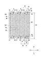
次に、図12および図13を参照して、レーザー光Lの照射について説明する。図12および図13において、スポットLSは、レーザー光Lのスポットを示す。スポット径d5は、例えば、0.2mmである。スポット径d5は、スポットLSの直径を示す。 Next, the irradiation of the laser beam L will be described with reference to FIGS. 12 and 13. In FIGS. 12 and 13, the spot LS indicates a spot of the laser beam L. The spot diameter d5 is, for example, 0.2 mm. The spot diameter d5 indicates the diameter of the spot LS.
図12に示すように、本実施形態に係るガス抜き部材140の製造方法では、環状領域RX1の端部に沿ってレーザー光Lの中心が移動するようにレーザー光Lを走査する。詳しくは、レーザー光Lの中心が、軌跡Aに沿って移動するようにレーザー光Lを走査する。この際、レーザー光LのスポットLSの一部が隣接するスポットLSの一部と重なる状態を保持しながら、レーザー光Lの中心は移動する。
As shown in FIG. 12, in the method for manufacturing the
まず、頂点A1を始点とし、辺S1に沿ってレーザー光Lの中心を移動させて、頂点A2までレーザー光Lを走査する。その結果、レーザー光Lが照射された金属粉末Mは固化される。具体的には、辺S1を中心として、スポット径d5の幅で金属粉末Mが固化される。 First, the center of the laser beam L is moved along the side S1 with the vertex A1 as the starting point, and the laser beam L is scanned to the vertex A2. As a result, the metal powder M irradiated with the laser beam L is solidified. Specifically, the metal powder M is solidified with a width of the spot diameter d5 centered on the side S1.
次に、辺S2に沿ってレーザー光Lの中心を移動させて、頂点A3までレーザー光Lを走査する。その結果、レーザー光Lが照射された金属粉末Mは固化される。具体的には、辺S2を中心として、スポット径d5の幅で金属粉末Mが固化される。 Next, the center of the laser beam L is moved along the side S2, and the laser beam L is scanned to the apex A3. As a result, the metal powder M irradiated with the laser beam L is solidified. Specifically, the metal powder M is solidified with a width of the spot diameter d5 centered on the side S2.
次に、辺S3に沿ってレーザー光Lの中心を移動させて、頂点A4までレーザー光Lを走査する。その結果、レーザー光Lが照射された金属粉末Mは固化される。具体的には、辺S3を中心として、スポット径d5の幅で金属粉末Mが固化される。 Next, the center of the laser beam L is moved along the side S3, and the laser beam L is scanned to the apex A4. As a result, the metal powder M irradiated with the laser beam L is solidified. Specifically, the metal powder M is solidified with a width of the spot diameter d5 centered on the side S3.
次に、辺S4に沿ってレーザー光Lの中心を移動させて、頂点A1までレーザー光Lを走査する。その結果、レーザー光Lが照射された金属粉末Mは固化される。具体的には、辺S4を中心として、スポット径d5の幅で金属粉末Mが固化される。 Next, the center of the laser beam L is moved along the side S4, and the laser beam L is scanned to the apex A1. As a result, the metal powder M irradiated with the laser beam L is solidified. Specifically, the metal powder M is solidified with a width of the spot diameter d5 centered on the side S4.
このようにして、照射領域Raに位置する金属粉末Mが固化される。照射領域Raは、レーザー光Lが照射される領域である。照射領域Raは、レーザー光Lの中心を軌跡Aに沿って移動させたときに、スポットLSが通過する領域である。換言すると、照射領域Raは、レーザー光Lの中心を環状領域RX1の端部に沿って移動させたときに、スポットLSが通過する領域である。 In this way, the metal powder M located in the irradiation region Ra is solidified. The irradiation area Ra is a region where the laser beam L is irradiated. The irradiation region Ra is a region through which the spot LS passes when the center of the laser beam L is moved along the locus A. In other words, the irradiation region Ra is a region through which the spot LS passes when the center of the laser beam L is moved along the end of the annular region RX1.
辺S2の長さd1および辺S4の長さd1は、スポット径d5よりも長い。具体的には、辺S2の長さd1および辺S4の長さd1は、0.21mmである。スポット径d5は、0.2mmである。したがって、辺S2の長さd1および辺S4の長さd1は、スポット径d5よりも0.01mm長い。したがって、環状領域RX1よりも内側に、幅0.01mmの非照射領域Rbが形成される。非照射領域Rbは、レーザー光Lが照射されない領域である。 The length d1 of the side S2 and the length d1 of the side S4 are longer than the spot diameter d5. Specifically, the length d1 of the side S2 and the length d1 of the side S4 are 0.21 mm. The spot diameter d5 is 0.2 mm. Therefore, the length d1 of the side S2 and the length d1 of the side S4 are 0.01 mm longer than the spot diameter d5. Therefore, a non-irradiated region Rb having a width of 0.01 mm is formed inside the annular region RX1. The non-irradiated region Rb is a region where the laser beam L is not irradiated.
また、辺S1の長さd8および辺S3の長さd8は、スポット径d5よりも十分に長い。したがって、環状領域RX1よりも内側に、非照射領域Rbが形成される。 Further, the length d8 of the side S1 and the length d8 of the side S3 are sufficiently longer than the spot diameter d5. Therefore, the non-irradiated region Rb is formed inside the annular region RX1.
また、隣接する環状領域Rの間隔d2は、スポット径d5よりも長い。具体的には、間隔d2は、0.21mmである。スポット径d5は、0.2mmである。したがって、隣接する環状領域Rの間には、幅0.01mmの非照射領域が形成される。 Further, the interval d2 of the adjacent annular regions R is longer than the spot diameter d5. Specifically, the interval d2 is 0.21 mm. The spot diameter d5 is 0.2 mm. Therefore, a non-irradiated region having a width of 0.01 mm is formed between the adjacent annular regions R.
軌跡Aに沿ってレーザー光Lの照射が完了した後、軌跡Aと同様に、軌跡Bに沿って、レーザー光Lの照射が行われる。その結果、軌跡Bに沿って、軌跡Bを中心としてスポット径d5の幅で、金属粉末Mが固化される。また、環状領域RX2よりも内側に、非照射領域Rbが形成される。その後、同様に、軌跡Cに沿って、レーザー光Lの照射が行われる。その結果、軌跡Cに沿って、軌跡Cを中心としてスポット径d5の幅で、金属粉末Mが固化される。また、環状領域RX3よりも内側に、非照射領域Rbが形成される。 After the irradiation of the laser light L is completed along the locus A, the laser light L is irradiated along the locus B in the same manner as the locus A. As a result, the metal powder M is solidified along the locus B with a width of the spot diameter d5 centered on the locus B. Further, a non-irradiated region Rb is formed inside the annular region RX2. After that, the laser beam L is similarly irradiated along the locus C. As a result, the metal powder M is solidified along the locus C with a width of the spot diameter d5 centered on the locus C. Further, a non-irradiated region Rb is formed inside the annular region RX3.
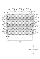
次に、図13に示すように、軌跡Aと同様に、軌跡Dに沿って、レーザー光Lの照射が行われる。その結果、環状領域RY1よりも内側に、非照射領域Rbが形成される。その後、同様に、軌跡Eに沿って、レーザー光Lの照射が行われる。その結果、環状領域RY2よりも内側に、非照射領域Rbが形成される。その後、同様に、軌跡Fに沿って、レーザー光Lの照射が行われる。その結果、環状領域RY3よりも内側に、非照射領域Rbが形成される。 Next, as shown in FIG. 13, the laser light L is irradiated along the locus D in the same manner as the locus A. As a result, the non-irradiated region Rb is formed inside the annular region RY1. After that, the laser beam L is similarly irradiated along the locus E. As a result, the non-irradiated region Rb is formed inside the annular region RY2. After that, the laser beam L is similarly irradiated along the locus F. As a result, the non-irradiated region Rb is formed inside the annular region RY3.
辺S1の長さd3および辺S3の長さd3は、スポット径d5よりも長い。具体的には、辺S1の長さおよび辺S3の長さは、0.21mmである。スポット径d5は、0.2mmである。したがって、辺S1の長さd3および辺S3の長さd3は、スポット径d5よりも0.01mm長い。したがって、環状領域RY1よりも内側に、幅0.01mmの非照射領域Rbが形成される。 The length d3 of the side S1 and the length d3 of the side S3 are longer than the spot diameter d5. Specifically, the length of the side S1 and the length of the side S3 are 0.21 mm. The spot diameter d5 is 0.2 mm. Therefore, the length d3 of the side S1 and the length d3 of the side S3 are 0.01 mm longer than the spot diameter d5. Therefore, a non-irradiated region Rb having a width of 0.01 mm is formed inside the annular region RY1.
また、辺S2の長さd8および辺S4の長さd8は、スポット径d5よりも十分に長い。したがって、環状領域RY1よりも内側に、非照射領域Rbが形成される。 Further, the length d8 of the side S2 and the length d8 of the side S4 are sufficiently longer than the spot diameter d5. Therefore, the non-irradiated region Rb is formed inside the annular region RY1.
また、隣接する環状領域Rの間隔d4は、スポット径d5よりも長い。具体的には、間隔d4は、0.21mmである。スポット径d5は、0.2mmである。したがって、隣接する環状領域Rの間には、幅0.01mmの非照射領域が形成される。 Further, the interval d4 of the adjacent annular regions R is longer than the spot diameter d5. Specifically, the interval d4 is 0.21 mm. The spot diameter d5 is 0.2 mm. Therefore, a non-irradiated region having a width of 0.01 mm is formed between the adjacent annular regions R.
図12および図13を参照して説明したように、軌跡A、軌跡B、軌跡C、軌跡D、軌跡Eおよび軌跡Fに沿って、レーザー光Lの照射が行われることによって、照射領域Raに位置する金属粉末Mが固化される。図13において、非照射領域Rbが重なる領域をハッチングで示している。ハッチングで示した領域は、照射領域Raに囲まれている。したがって、ハッチングで示した領域に貫通孔1414が形成される。本実施形態では、貫通孔1414の直径は、0.01mmである。このように、本実施形態によれば、スポット径d5よりも、十分に小さい貫通孔1414を容易に形成することができる。
As described with reference to FIGS. 12 and 13, the irradiation region Ra is subjected to the irradiation of the laser beam L along the locus A, the locus B, the locus C, the locus D, the locus E, and the locus F. The located metal powder M is solidified. In FIG. 13, the regions where the non-irradiated regions Rb overlap are shown by hatching. The area shown by hatching is surrounded by the irradiation area Ra. Therefore, a through
以上、図10〜図13を参照して説明したように、本実施形態に係るガス抜き部材140の製造方法によれば、環状の環状領域Rの端部に沿ってレーザー光Lの中心が移動するようにレーザー光Lを走査して、環状領域Rよりも内側に、レーザー光が照射されない非照射領域Rbを形成する。したがって、非照射領域Rbに貫通孔1414を容易に形成することができる。その結果、容易に多孔質の構造を形成することができる。
As described above with reference to FIGS. 10 to 13, according to the method for manufacturing the
また、本実施形態に係るガス抜き部材140の製造方法は、第1走査工程と、第2走査工程とを有する。第1走査工程において、第1辺(辺S1および辺S3)に沿ってレーザー光Lの中心が移動する。第2走査工程において、第2辺(辺S2および辺S4)に沿ってレーザー光の中心が移動する。第1辺(辺S1および辺S3)の長さは、レーザー光Lのスポット径d5よりも長い。第2辺(辺S2および辺S4)の長さは、レーザー光Lのスポット径d5よりも長い。したがって、環状領域Rよりも内側に、非照射領域Rbが形成される。その結果、非照射領域Rbに貫通孔1414を容易に形成することができる。
Further, the method for manufacturing the
また、複数の環状領域は、第1環状領域(環状領域RX1、環状領域RX2および環状領域RX3)と、第2環状領域(環状領域RY1、環状領域RY2および環状領域RY3)とを含む。第1環状領域は、所定方向(Y軸方向)に延びる。第2環状領域は、交差方向(X軸方向)に延びる。したがって、第1環状領域と第2環状領域とは交差する。その結果、第1環状領域の非照射領域Rbと、第2環状領域の非照射領域Rbとが交差する。その結果、第1環状領域の非照射領域Rbと、第2環状領域の非照射領域Rbとが重なった領域に、容易に貫通孔1414を容易に形成することができる。
Further, the plurality of annular regions include a first annular region (annular region RX1, annular region RX2 and annular region RX3) and a second annular region (annular region RY1, annular region RY2 and annular region RY3). The first annular region extends in a predetermined direction (Y-axis direction). The second annular region extends in the crossing direction (X-axis direction). Therefore, the first annular region and the second annular region intersect. As a result, the non-irradiated region Rb of the first annular region and the non-irradiated region Rb of the second annular region intersect. As a result, the through
また、隣接する環状領域Rの間隔(間隔d2および間隔d4)は、レーザー光Lのスポット径d5よりも長い。このため、隣接する環状領域Rの間にも非照射領域Rbを形成することができる。したがって、隣接する環状領域Rの間にも貫通孔1414を容易に形成することができる。その結果、形成される貫通孔1414の数を増やすことができる。
Further, the interval (interval d2 and interval d4) of the adjacent annular regions R is longer than the spot diameter d5 of the laser beam L. Therefore, the non-irradiated region Rb can be formed between the adjacent annular regions R. Therefore, the through
以上、図面(図1〜図13)を参照しながら本発明の実施形態を説明した。但し、本発明は、上記の実施形態に限られるものではなく、その要旨を逸脱しない範囲で種々の態様において実施することが可能である(例えば、下記に示す(1)〜(5))。図面は、理解しやすくするために、それぞれの構成要素を主体に模式的に示しており、図示された各構成要素の厚み、長さ、個数等は、図面作成の都合上から実際とは異なる。また、上記の実施形態で示す各構成要素の材質や形状、寸法等は一例であって、特に限定されるものではなく、本発明の効果から実質的に逸脱しない範囲で種々の変更が可能である。 The embodiments of the present invention have been described above with reference to the drawings (FIGS. 1 to 13). However, the present invention is not limited to the above-described embodiment, and can be implemented in various embodiments without departing from the gist thereof (for example, (1) to (5) shown below). The drawings are schematically shown mainly for each component for easy understanding, and the thickness, length, number, etc. of each component shown are different from the actual ones for the convenience of drawing creation. .. Further, the material, shape, dimensions, etc. of each component shown in the above-described embodiment are merely examples, and are not particularly limited, and various changes can be made without substantially deviating from the effects of the present invention. is there.
(1)実施形態1〜実施形態6に係る金型100では、ベント170は、接続経路172を有していたが、本発明はこれに限定されない。例えば、ベント170は、排出経路174のみを有していてもよい。
(1) In the
(2)実施形態1〜実施形態46に係る金型100では、キャビティ130に充填される成形品の材料は、樹脂であったが、本発明はこれに限定されない。例えば、キャビティ130に充填される成形品の材料は、金属でもよい。
(2) In the
(3)実施形態1〜実施形態6に係る金型100では、金型部材110および金型部材120は、金属製であったが、本発明はこれに限定されない。例えば、金型部材110および金型部材120は、樹脂製であってもよい。
(3) In the
(4)実施形態1〜実施形態6に係る金型100では、ガス抜き部材140は円柱状であったが、本発明はこれに限定されない。例えば、ガス抜き部材140は直方体状でもよい。この場合、ガス抜き部材140が取り付けられる凹部112は、直方体状である。ガス抜き部材140を直方体状にすることによって、凹部112にガス抜き部材140を取り付けた際、ガス抜き部材140が回転することを抑制することができる。
(4) In the
(5)実施形態7に係るガス抜き部材140の製造方法では、環状領域Rは矩形状であったが、本発明はこれに限定されない。例えば、台形状または多角形状であってもよい。
(5) In the method for manufacturing the
100 金型
110 金型部材(第1金型部材)
120 金型部材(第2金型部材)
130 キャビティ(材料流通部)
140 ガス抜き部材
141 第1面
142 側面
143 第2面
144 排出部
160、160a、160b ランナー(材料流通部)
174 排出経路
180 金型部材
1412 流入部
1414 貫通孔
D1 第1方向
D2 第2方向
L レーザー光
M 金属粉末
Sa 流通空間
R 環状領域
RX1、RX2、RX3 環状領域(第1環状領域)
RY1、RY2、RY3 環状領域(第2環状領域)
Rb 非照射領域
S1、S3 辺(第1辺)
S2、S4 辺(第2辺)
100
120 mold member (second mold member)
130 Cavity (Material Distribution Department)
140
174
RY1, RY2, RY3 annular region (second annular region)
Rb non-irradiated area S1, S3 side (first side)
S2, S4 side (second side)
Claims (5)
環状の環状領域の端部に沿って前記レーザー光の中心が移動するように前記レーザー光を走査して、前記環状領域よりも内側に、前記レーザー光が照射されない非照射領域を形成する、ガス抜き部材の製造方法。 It is a manufacturing method that manufactures a degassing member by irradiating the spread metal powder with laser light and solidifying it.
A gas that scans the laser beam so that the center of the laser beam moves along the end of the annular region to form a non-irradiated region inside the annular region that is not irradiated with the laser beam. Manufacturing method of punched member.
所定方向に延びる第1辺と、
前記所定方向と交差する交差方向に延びる第2辺と
を有し、
前記第1辺に沿って前記レーザー光の中心が移動する第1走査工程と、
前記第2辺に沿って前記レーザー光の中心が移動する第2走査工程と
を包含し、
前記第1辺の長さは、前記レーザー光のスポット径よりも長く、
前記第2辺の長さは、前記レーザー光のスポット径よりも長い、請求項1に記載のガス抜き部材の製造方法。 The annular region
The first side extending in a predetermined direction and
It has a second side extending in an intersecting direction that intersects the predetermined direction, and has.
The first scanning step in which the center of the laser beam moves along the first side, and
Including a second scanning step in which the center of the laser beam moves along the second side.
The length of the first side is longer than the spot diameter of the laser beam.
The method for manufacturing a degassing member according to claim 1, wherein the length of the second side is longer than the spot diameter of the laser beam.
複数の前記環状領域は、
前記所定方向に延びる第1環状領域と、
前記交差方向に延びる第2環状領域と
を含む、請求項2に記載のガス抜き部材の製造方法。 The annular region is plural
The plurality of said annular regions
The first annular region extending in the predetermined direction and
The method for manufacturing a degassing member according to claim 2, further comprising a second annular region extending in the intersecting direction.
隣接する前記環状領域の間隔は、前記レーザー光のスポット径よりも長い、請求項1から請求項4いずれか1項に記載のガス抜き部材の製造方法。 The annular region is plural
The method for manufacturing a degassing member according to any one of claims 1 to 4, wherein the distance between the adjacent annular regions is longer than the spot diameter of the laser beam.
Priority Applications (1)
| Application Number | Priority Date | Filing Date | Title |
|---|---|---|---|
| JP2019180187A JP6703689B1 (en) | 2019-09-30 | 2019-09-30 | Method for manufacturing mold degassing member |
Applications Claiming Priority (1)
| Application Number | Priority Date | Filing Date | Title |
|---|---|---|---|
| JP2019180187A JP6703689B1 (en) | 2019-09-30 | 2019-09-30 | Method for manufacturing mold degassing member |
Related Parent Applications (1)
| Application Number | Title | Priority Date | Filing Date |
|---|---|---|---|
| JP2019111457A Division JP6664721B1 (en) | 2019-06-14 | 2019-06-14 | Mold |
Publications (2)
| Publication Number | Publication Date |
|---|---|
| JP6703689B1 JP6703689B1 (en) | 2020-06-03 |
| JP2020203473A true JP2020203473A (en) | 2020-12-24 |
Family
ID=70858250
Family Applications (1)
| Application Number | Title | Priority Date | Filing Date |
|---|---|---|---|
| JP2019180187A Active JP6703689B1 (en) | 2019-09-30 | 2019-09-30 | Method for manufacturing mold degassing member |
Country Status (1)
| Country | Link |
|---|---|
| JP (1) | JP6703689B1 (en) |
Citations (7)
| Publication number | Priority date | Publication date | Assignee | Title |
|---|---|---|---|---|
| JPH0766533A (en) * | 1993-08-26 | 1995-03-10 | Matsushita Electric Works Ltd | Manufacture circuit board |
| JP2008173887A (en) * | 2007-01-19 | 2008-07-31 | Ngk Insulators Ltd | Degassing member for injection molding mold |
| WO2012124828A1 (en) * | 2011-03-17 | 2012-09-20 | パナソニック株式会社 | Production method for three-dimensionally shaped object and three-dimensionally shaped object |
| JP2014121816A (en) * | 2012-12-20 | 2014-07-03 | Futaba Corp | Mold |
| WO2016017155A1 (en) * | 2014-07-30 | 2016-02-04 | パナソニックIpマネジメント株式会社 | Method for producing three-dimensionally shaped molded article, and three-dimensionally shaped molded article |
| JP2017001263A (en) * | 2015-06-09 | 2017-01-05 | 株式会社ブリヂストン | Mold for rubber article and method for producing mold for rubber article |
| JP2017177560A (en) * | 2016-03-30 | 2017-10-05 | 三光合成株式会社 | Gas discharge and supply structure |
-
2019
- 2019-09-30 JP JP2019180187A patent/JP6703689B1/en active Active
Patent Citations (8)
| Publication number | Priority date | Publication date | Assignee | Title |
|---|---|---|---|---|
| JPH0766533A (en) * | 1993-08-26 | 1995-03-10 | Matsushita Electric Works Ltd | Manufacture circuit board |
| JP2008173887A (en) * | 2007-01-19 | 2008-07-31 | Ngk Insulators Ltd | Degassing member for injection molding mold |
| WO2012124828A1 (en) * | 2011-03-17 | 2012-09-20 | パナソニック株式会社 | Production method for three-dimensionally shaped object and three-dimensionally shaped object |
| JP2014121816A (en) * | 2012-12-20 | 2014-07-03 | Futaba Corp | Mold |
| WO2016017155A1 (en) * | 2014-07-30 | 2016-02-04 | パナソニックIpマネジメント株式会社 | Method for producing three-dimensionally shaped molded article, and three-dimensionally shaped molded article |
| JP2017001263A (en) * | 2015-06-09 | 2017-01-05 | 株式会社ブリヂストン | Mold for rubber article and method for producing mold for rubber article |
| JP2017177560A (en) * | 2016-03-30 | 2017-10-05 | 三光合成株式会社 | Gas discharge and supply structure |
| WO2017169830A1 (en) * | 2016-03-30 | 2017-10-05 | 三光合成株式会社 | Gas discharge and supply structure |
Also Published As
| Publication number | Publication date |
|---|---|
| JP6703689B1 (en) | 2020-06-03 |
Similar Documents
| Publication | Publication Date | Title |
|---|---|---|
| US20170066052A1 (en) | METHOD FOR MANUFACTURING THREE-DIMENSIONAL SHAPED OBJECT (As Amended) | |
| RU2737286C1 (en) | Apparatus and method of controlling an irradiation system for making articles | |
| US10413970B2 (en) | Method for manufacturing three-dimensional shaped object and three-dimensional shaped object | |
| KR101826024B1 (en) | Nozzle for materials extrusion type 3d printer | |
| US10538021B2 (en) | Injection mold | |
| JP2014004802A (en) | Resin molded product obtained by integrating metal member and method for manufacturing the same | |
| US7625199B2 (en) | Plastic filter | |
| JP2016147404A (en) | Manufacturing method of bonded structure and bonded structure | |
| JP2020203398A (en) | Metal-mold | |
| JP2020203473A (en) | Method for manufacturing degassing member for mold | |
| JP6731642B2 (en) | Method for manufacturing three-dimensional shaped object | |
| CN104345495B (en) | The production method of planar illuminating device and light guide plate | |
| CN109996587B (en) | Ridge filter and method of making the same | |
| CN112236252B (en) | Powder removal of floating structures | |
| EP4049829B1 (en) | Support structure and a three-dimensional object and method of producing the same | |
| JP6993271B2 (en) | Manufacturing method of resin parts | |
| EP3950353B1 (en) | Production method for three-dimensional shaped object | |
| JP2017042984A5 (en) | ||
| KR101498934B1 (en) | 3D Printer and Method for Controlling The Same | |
| US12480257B2 (en) | 3D printed tooling for pulp molding process | |
| JP2005059574A (en) | Manufacturing method of three-dimensional shaped object | |
| JP6858383B1 (en) | Mold bushes and molds | |
| JP2021138977A (en) | Method for manufacturing three-dimensionally shaped molding and three-dimensionally shaped molding | |
| JP2003011111A (en) | Mold for forming honeycomb structure and method for manufacturing the same | |
| EP3466550B1 (en) | Screening system |
Legal Events
| Date | Code | Title | Description |
|---|---|---|---|
| A621 | Written request for application examination |
Free format text: JAPANESE INTERMEDIATE CODE: A621 Effective date: 20190930 |
|
| A871 | Explanation of circumstances concerning accelerated examination |
Free format text: JAPANESE INTERMEDIATE CODE: A871 Effective date: 20190930 |
|
| A975 | Report on accelerated examination |
Free format text: JAPANESE INTERMEDIATE CODE: A971005 Effective date: 20191204 |
|
| A131 | Notification of reasons for refusal |
Free format text: JAPANESE INTERMEDIATE CODE: A131 Effective date: 20200107 |
|
| A521 | Request for written amendment filed |
Free format text: JAPANESE INTERMEDIATE CODE: A523 Effective date: 20200123 |
|
| TRDD | Decision of grant or rejection written | ||
| A01 | Written decision to grant a patent or to grant a registration (utility model) |
Free format text: JAPANESE INTERMEDIATE CODE: A01 Effective date: 20200317 |
|
| A61 | First payment of annual fees (during grant procedure) |
Free format text: JAPANESE INTERMEDIATE CODE: A61 Effective date: 20200326 |
|
| R150 | Certificate of patent or registration of utility model |
Ref document number: 6703689 Country of ref document: JP Free format text: JAPANESE INTERMEDIATE CODE: R150 |
|
| R250 | Receipt of annual fees |
Free format text: JAPANESE INTERMEDIATE CODE: R250 |
|
| S533 | Written request for registration of change of name |
Free format text: JAPANESE INTERMEDIATE CODE: R313533 |
|
| R350 | Written notification of registration of transfer |
Free format text: JAPANESE INTERMEDIATE CODE: R350 |
|
| R250 | Receipt of annual fees |
Free format text: JAPANESE INTERMEDIATE CODE: R250 |