JP2020512925A - Automatic fluid injection device - Google Patents
Automatic fluid injection device Download PDFInfo
- Publication number
- JP2020512925A JP2020512925A JP2020504451A JP2020504451A JP2020512925A JP 2020512925 A JP2020512925 A JP 2020512925A JP 2020504451 A JP2020504451 A JP 2020504451A JP 2020504451 A JP2020504451 A JP 2020504451A JP 2020512925 A JP2020512925 A JP 2020512925A
- Authority
- JP
- Japan
- Prior art keywords
- injection
- needle
- puncture
- actuator
- ring
- Prior art date
- Legal status (The legal status is an assumption and is not a legal conclusion. Google has not performed a legal analysis and makes no representation as to the accuracy of the status listed.)
- Granted
Links
Images




Classifications
-
- A—HUMAN NECESSITIES
- A61—MEDICAL OR VETERINARY SCIENCE; HYGIENE
- A61M—DEVICES FOR INTRODUCING MEDIA INTO, OR ONTO, THE BODY; DEVICES FOR TRANSDUCING BODY MEDIA OR FOR TAKING MEDIA FROM THE BODY; DEVICES FOR PRODUCING OR ENDING SLEEP OR STUPOR
- A61M5/00—Devices for bringing media into the body in a subcutaneous, intra-vascular or intramuscular way; Accessories therefor, e.g. filling or cleaning devices, arm-rests
- A61M5/14—Infusion devices, e.g. infusing by gravity; Blood infusion; Accessories therefor
- A61M5/142—Pressure infusion, e.g. using pumps
- A61M5/145—Pressure infusion, e.g. using pumps using pressurised reservoirs, e.g. pressurised by means of pistons
-
- A—HUMAN NECESSITIES
- A61—MEDICAL OR VETERINARY SCIENCE; HYGIENE
- A61M—DEVICES FOR INTRODUCING MEDIA INTO, OR ONTO, THE BODY; DEVICES FOR TRANSDUCING BODY MEDIA OR FOR TAKING MEDIA FROM THE BODY; DEVICES FOR PRODUCING OR ENDING SLEEP OR STUPOR
- A61M5/00—Devices for bringing media into the body in a subcutaneous, intra-vascular or intramuscular way; Accessories therefor, e.g. filling or cleaning devices, arm-rests
- A61M5/14—Infusion devices, e.g. infusing by gravity; Blood infusion; Accessories therefor
- A61M5/142—Pressure infusion, e.g. using pumps
- A61M5/145—Pressure infusion, e.g. using pumps using pressurised reservoirs, e.g. pressurised by means of pistons
- A61M2005/14506—Pressure infusion, e.g. using pumps using pressurised reservoirs, e.g. pressurised by means of pistons mechanically driven, e.g. spring or clockwork
-
- A—HUMAN NECESSITIES
- A61—MEDICAL OR VETERINARY SCIENCE; HYGIENE
- A61M—DEVICES FOR INTRODUCING MEDIA INTO, OR ONTO, THE BODY; DEVICES FOR TRANSDUCING BODY MEDIA OR FOR TAKING MEDIA FROM THE BODY; DEVICES FOR PRODUCING OR ENDING SLEEP OR STUPOR
- A61M2205/00—General characteristics of the apparatus
- A61M2205/02—General characteristics of the apparatus characterised by a particular materials
- A61M2205/0266—Shape memory materials
-
- A—HUMAN NECESSITIES
- A61—MEDICAL OR VETERINARY SCIENCE; HYGIENE
- A61M—DEVICES FOR INTRODUCING MEDIA INTO, OR ONTO, THE BODY; DEVICES FOR TRANSDUCING BODY MEDIA OR FOR TAKING MEDIA FROM THE BODY; DEVICES FOR PRODUCING OR ENDING SLEEP OR STUPOR
- A61M2205/00—General characteristics of the apparatus
- A61M2205/36—General characteristics of the apparatus related to heating or cooling
- A61M2205/3653—General characteristics of the apparatus related to heating or cooling by Joule effect, i.e. electric resistance
Landscapes
- Health & Medical Sciences (AREA)
- Vascular Medicine (AREA)
- Engineering & Computer Science (AREA)
- Anesthesiology (AREA)
- Biomedical Technology (AREA)
- Heart & Thoracic Surgery (AREA)
- Hematology (AREA)
- Life Sciences & Earth Sciences (AREA)
- Animal Behavior & Ethology (AREA)
- General Health & Medical Sciences (AREA)
- Public Health (AREA)
- Veterinary Medicine (AREA)
- Infusion, Injection, And Reservoir Apparatuses (AREA)
Abstract
自動流体注入装置であって、注射部位に接触するための支持体(2)に固定された本体(1)と、注射針(40)および形状記憶合金からなる穿刺アクチュエータ(49)を含む針アセンブリ(4)と、注射機構(7,8,9,10,11)とを備える。本体は流体が入れられた1以上の容器(5)を含む。容器は注射ピストン(6)を有する。穿刺バネ(48)および退避バネ(46)は、休止時は阻止手段に圧縮された状態で保持されている。穿刺アクチュエータ(49)を最大収縮の50%に到達するまで加熱により作動させると、アクチュエータリング(47)が穿刺リング(45)に対して移動して、針支持部(44)が解放されて穿刺バネが伸張して注射針が注射部位に挿入する。穿刺アクチュエータを最大収縮の100%に到達するまで加熱により作動させると、アクチュエータリングが退避リング(42)に対して移動して、退避バネが注射針を注射部位から退避させる。【選択図】 図1A needle assembly comprising an automatic fluid injection device, a body (1) fixed to a support (2) for contacting an injection site, a needle (40) and a puncture actuator (49) made of a shape memory alloy. (4) and an injection mechanism (7, 8, 9, 10, 11). The body comprises one or more containers (5) containing a fluid. The container has an injection piston (6). The puncture spring (48) and the retracting spring (46) are held in a compressed state by the blocking means at rest. When the puncture actuator (49) is activated by heating until it reaches 50% of maximum contraction, the actuator ring (47) moves relative to the puncture ring (45), releasing the needle support (44) and puncturing. The spring extends and the needle inserts into the injection site. When the puncture actuator is activated by heating until it reaches 100% of maximum contraction, the actuator ring moves relative to the retract ring (42) and the retract spring retracts the needle from the injection site. [Selection diagram]
Description
本発明は、自動流体注入装置に関する。 The present invention relates to an automatic fluid injection device.
自動流体注入装置は公知技術であり、特に自己注射器が含まれる。自己注射器では、一般的にはシリンジである容器に入れられた流体が、アクチュエータシステムによって自動的に注射される。このアクチュエータシステムは、通常は負荷バネを含み、起動するとピストンを容器の内部で移動させることにより流体が注射される。 Automatic fluid injection devices are well known in the art, and include self-injectors, among others. In an auto-injector, a fluid contained in a container, typically a syringe, is automatically injected by an actuator system. The actuator system typically includes a load spring, which when activated causes fluid to be injected by moving a piston inside the container.
そのような従来の装置には、問題が生じることがある。具体的には、投与流体が多量であったり比較的粘性であったり、複数種類の流体を組み合わせて1回で投与する必要があったりする場合である。 Problems can arise with such conventional devices. Specifically, there are cases where a large amount of fluid is administered, it is relatively viscous, or it is necessary to combine a plurality of types of fluids and administer them once.
特許文献1〜4は、従来の装置を開示している。 Patent Documents 1 to 4 disclose conventional devices.
本発明の目的は、上述の問題が生じない自動流体注入装置を提供することである。 It is an object of the present invention to provide an automatic fluid injection device which does not have the above mentioned problems.
本発明の別の目的は、流体が多量および/または高粘性であっても自動注入が可能な自動流体注入装置を提供することである。 Another object of the present invention is to provide an automatic fluid injection device capable of automatic injection even if the fluid is large in volume and / or highly viscous.
本発明のさらに別の目的は、製造および組立が容易で安価な自動流体注入装置を提供することである。 Yet another object of the present invention is to provide an automatic fluid injection device that is easy and inexpensive to manufacture and assemble.
よって本発明は、自動流体注入装置であって、注射部位に接触するための支持体に固定された本体と、前記注射部位を突き刺すための注射針および形状記憶合金からなる穿刺アクチュエータを含む針アセンブリと、注射機構とを備える自動流体注入装置を提供する。前記本体は流体が入れられた1以上の容器を含む。前記容器はその内部に注射ピストンを有する。前記注射機構は、退避リングと、針支持部と、前記穿刺アクチュエータの一端が固定された穿刺リングと、退避バネと、アクチュエータリングと、穿刺バネとを含む。前記穿刺バネおよび退避バネは、休止時はそれぞれに対応する阻止手段により圧縮された状態で保持されている。前記穿刺アクチュエータを、その収縮が最大収縮の50%に到達するまで加熱により作動させると、前記アクチュエータリングが前記穿刺リングに対して移動することによって、前記針支持部が解放されて前記穿刺バネが伸張して、前記注射針が前記注射部位に挿入する。前記穿刺アクチュエータを、その収縮が最大収縮の100%に到達するまで加熱により作動させると、前記アクチュエータリングが前記退避リングに対して移動することによって、前記穿刺リングと、前記針支持部および前記注射針が相互に連結したアセンブリとが解放されて、前記退避バネが前記注射針を前記注射部位から退避させる。 Accordingly, the present invention is an automatic fluid injection device, comprising a main body fixed to a support for contacting an injection site, a needle assembly for piercing the injection site, and a puncture actuator made of a shape memory alloy. And an automatic fluid injection device including an injection mechanism. The body includes one or more containers containing a fluid. The container has an injection piston therein. The injection mechanism includes a retraction ring, a needle support, a puncture ring to which one end of the puncture actuator is fixed, a retraction spring, an actuator ring, and a puncture spring. The puncture spring and the retracting spring are held in a compressed state by the corresponding blocking means at rest. When the puncture actuator is actuated by heating until its contraction reaches 50% of maximum contraction, the actuator ring moves relative to the puncture ring, releasing the needle support and causing the puncture spring to move. Upon extension, the needle inserts into the injection site. When the puncture actuator is actuated by heating until its contraction reaches 100% of maximum contraction, the actuator ring moves relative to the retraction ring to cause the puncture ring, the needle support and the injection. The assembly of interconnected needles is released and the retraction spring retracts the injection needle from the injection site.
有利には、前記穿刺アクチュエータは、ワイヤであり、好ましくはニッケル・チタン合金(ニチノール)からなるワイヤである。 Advantageously, the puncture actuator is a wire, preferably of nickel-titanium alloy (Nitinol).
有利には、前記ワイヤは、加熱によりマルテンサイト相に変態して、その物理的寸法、具体的には長さが変化する。 Advantageously, the wire transforms into the martensitic phase on heating, changing its physical dimensions, in particular its length.
有利には、前記注射機構は、膨張性材料を含むアクチュエータキャップと、前記膨張性材料を加熱して膨張させて、前記注射ピストンを前記容器の内部で移動させることにより、前記注射針から前記流体を前記注射部位に注入させる加熱手段とを含む。 Advantageously, the injection mechanism comprises an actuator cap containing an expandable material and the fluid from the injection needle by heating and expanding the expandable material to move the injection piston within the container. Heating means for injecting into the injection site.
有利には、前記膨張性材料は、熱膨張性微小球体を含む。 Advantageously, the expandable material comprises thermally expandable microspheres.
有利には、前記熱膨張性微小球体は、炭化水素を封入した中空の熱可塑性微小球体を含む。 Advantageously, the heat-expandable microspheres comprise hollow hydrocarbon microspheres encapsulating a hydrocarbon.
有利には、前記熱可塑性微小球体が60℃〜90℃の温度範囲に加熱されて膨張して気相に変態することにより、前記熱膨張性微小球体は元の体積の5倍〜70倍に膨張する。 Advantageously, the thermoplastic microspheres are heated to a temperature range of 60 ° C. to 90 ° C. to expand and transform into a gas phase, whereby the thermoexpandable microspheres have a volume of 5 to 70 times the original volume. Expands.
有利には、前記支持体は、前記注射部位に固定するためのステッカーを有する。 Advantageously, the support has a sticker for fixing it to the injection site.
有利には、前記容器それぞれに入れられた流体の量は、1ミリリットル(mL)〜10mLの範囲であり、好ましくは約3mLである。 Advantageously, the volume of fluid contained in each of said vessels is in the range of 1 milliliter (mL) to 10 mL, preferably about 3 mL.
有利には、前記容器の数は、複数であり、好ましくは3つである。 Advantageously, the number of said containers is more than one, preferably three.
有利には、前記自動流体注入装置は、さらに、電源手段、好ましくは任意の充電池を備える。 Advantageously, said automatic fluid injection device further comprises power supply means, preferably an optional rechargeable battery.
以下に示す詳細な説明および添付図面は、非限定的な例に基づいて本発明の特徴や利点を明確にするものである。
本発明は、比較的多量の流体の投与に特に適した自動流体注入装置に関する。投与流体は、典型的には1mL〜10mLの範囲である約数mLであり、例えば3mLである。また本発明の自動流体注入装置は、比較的粘性の流体の投与にも適している。 The present invention relates to an automatic fluid injection device which is particularly suitable for the administration of relatively large volumes of fluid. The dosing fluid is about a few mL, typically in the range 1 mL to 10 mL, for example 3 mL. The automatic fluid injection device of the present invention is also suitable for administration of relatively viscous fluids.
本発明の装置は、使い捨て式であることが好ましく、以下の手順により操作可能である。 The device of the present invention is preferably disposable and can be operated by the following procedure.
1)装置を包装から取り出して、注射部位に例えば専用のステッカーで固定する。 1) Remove the device from the packaging and secure it at the injection site, eg with a special sticker.
2)アクチュエータボタン200を押下して装置を作動させる。具体的には、プライミング、注射針の注射部位への挿入、流体の投与、および注射針の退避を行う。 2) Press the actuator button 200 to activate the device. Specifically, priming, insertion of the injection needle into the injection site, administration of fluid, and withdrawal of the injection needle are performed.
3)注射処置が終了するとその旨が通知されるので、装置を体から離して処分する。 3) When the injection procedure is over, you will be informed of this fact, and dispose of the device away from your body.
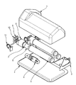
図1は、好適な実施形態に係る自動流体注入装置を示す。 FIG. 1 shows an automatic fluid injection device according to a preferred embodiment.
装置は、本体1と、プライミングアセンブリ3と、針アセンブリ4と、注射機構7〜11と、電源手段(図示せず)とを備える。本体1は、注射部位に接触するための支持体2に固定されており、流体が入れられた1以上の容器5を含む。容器5はその内部に注射ピストン6を有する。プライミングアセンブリ3は、プライミングアクチュエータと、容器5を突き刺すための1以上のプライミング針31とを含む。針アセンブリ4は、注射部位を突き刺すための注射針40(図1には図示せず)を含む。
The device comprises a body 1, a priming assembly 3, a needle assembly 4, injection mechanisms 7-11 and power supply means (not shown). The body 1 is fixed to a
一例として、電源手段は任意の充電池でもよい。 As an example, the power supply means may be any rechargeable battery.
本実施形態に係る注射機構は熱式である。 The injection mechanism according to this embodiment is a thermal type.
本実施形態に係るシステムは、3つの容器5に、プライミングアセンブリ3および針アセンブリ4を組み合わせている。
The system according to the present embodiment combines three
装置を作動させると、以下に示す一連の内部制御プロセスが生じる。 When the device is activated, the following series of internal control processes occur.
1)プライミングアセンブリ3が作動して、プライミングコントローラに膜体または容器への突き刺しの完了を通知する。なお、プライミングアセンブリ3にマイクロスイッチのような通知機構を含めてもよい。 1) The priming assembly 3 is activated to notify the priming controller that the piercing of the membrane or container has been completed. The priming assembly 3 may include a notification mechanism such as a micro switch.
2)注射針が電子制御式機構により挿入する。このシステムにも、注射コントローラに穿刺の完了を通知する通知部を含めてもよい。 2) The injection needle is inserted by an electronically controlled mechanism. This system may also include a notification unit that notifies the injection controller of the completion of the puncture.
3)注射機構が作動する。 3) The injection mechanism operates.
4)注射針が電子制御式機構により退避する。マイクロスイッチやオープンループタイマーなどの通知機構により(例えばダイオードを用いて視覚的におよび/または例えば音声信号を用いて聴覚的に)、ユーザに装置を体から離してもよいことを通知する。 4) The injection needle is retracted by the electronically controlled mechanism. A notification mechanism such as a microswitch or an open loop timer (eg, visually using a diode and / or audibly using an audio signal, for example) notifies the user that the device may be removed from the body.
上述のシーケンスでは、プライミングアセンブリおよび注射アセンブリに、具体的にはプライミング針および注射針に、少量の空気が含まれることがある。このような状態で装置が使用されると、針に空気が含まれたまま、皮下組織に流体が注入されることになる。 In the sequence described above, the priming assembly and the injection assembly, and in particular the priming needle and the injection needle, may contain a small amount of air. When the device is used in such a state, fluid is injected into the subcutaneous tissue while the needle contains air.
空気の含有を微量でも許容できない場合は、装置の作動シーケンスに以下の追加ステップ1.1を含めてもよい。 If even a small amount of air is unacceptable, the operating sequence of the device may include the following additional step 1.1.
1.1)プライミングが完了してから注射針が注射部位に挿入するまでの間に、早めに注射機構を作動させて、容器から少量の流体を吐出してプライミングアセンブリおよび注射アセンブリの空気を抜く。 1.1) Activate the injection mechanism early to expel a small amount of fluid from the container to evacuate the priming assembly and the injection assembly between the completion of priming and the insertion of the injection needle into the injection site. .
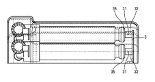
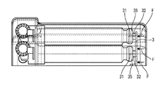
有利には、図2および図3から分かるように、作動するまでは容器5はセプタムからなる膜体35で塞がれており、作動が開始すると各容器に対応するプライミング針31が突き刺ささる。
Advantageously, as can be seen from FIGS. 2 and 3, the
プライミングアセンブリ3は、線形プライミングアクチュエータ(図示せず)に制御される単一の運動軸上を移動することが好ましい。 The priming assembly 3 preferably moves on a single axis of motion controlled by a linear priming actuator (not shown).
プライミングアクチュエータとしては、適切な方式のものが考えられる。具体的には、形状記憶合金(SMA)アクチュエータ、電磁ソレノイド式アクチュエータおよび電磁ウォームギア式アクチュエータである。 An appropriate type of priming actuator can be considered. Specifically, it is a shape memory alloy (SMA) actuator, an electromagnetic solenoid type actuator, and an electromagnetic worm gear type actuator.
装置を作動させると、プライミングアセンブリ3は以下の動作を実行する。 When the device is activated, the priming assembly 3 performs the following operations.
1)プライミング針31は、休止時において作動開始までは、例えばエラストマーからなるマスク32でそれぞれ塞がれているので、滅菌状態が維持される。
1) The priming needles 31 are closed by a
2)プライミングアクチュエータが作動すると、図3の矢印Fが示すように、プライミングアセンブリ3は容器5の膜体35に向かって進む。
2) When the priming actuator is actuated, the priming assembly 3 advances toward the
3)針マスク32が容器5に押し付けられて変形するので、プライミング針31は膜体35を連続的に進行して、容器5に突き刺さる。
3) Since the
4)薬剤が適切に投与される間、プライミングアクチュエータはプライミング針31の位置がずれないようにする。
4) The priming actuator keeps the priming
上記実施形態により得られる利点を以下に詳述する。 The advantages obtained by the above embodiment will be described in detail below.
1)プライミング針31は、休止時は無菌環境で保護されている。
1) The priming
2)プライミングアセンブリ3は、容器5が1つでもあれば機能する。よって、プライミング針31のうち、未使用のままであったり容器に突き刺さらなかったりする針があれば、システムは、そのような針に対しては機能せず、残りの針のために機能する。
2) The priming assembly 3 works if there is at least one
プライミングが完了すると、穿刺アクチュエータにより針アセンブリ4の注射針40が患者の注射部位に挿入する。
When priming is completed, the
図1〜図3に例示するように容器5を複数用いる場合、容器5それぞれに対応して突き刺さるプライミング針31は、いずれも単一の注射針40に連結している。
When a plurality of
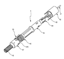
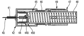
有利には、針アセンブリ4は、注射針40の他に、任意の針スリーブ41と、退避リング42と、針支持部44と、穿刺リング45と、退避バネ46と、アクチュエータリング47と、穿刺バネ48と、形状記憶合金(SMA)からなる穿刺アクチュエータとを備える。本実施形態では、穿刺アクチュエータはワイヤ49である。
Advantageously, the needle assembly 4 includes, in addition to the
ニッケル・チタン合金(ニチノール)のようなSMA材料は、加熱によりマルテンサイト相に変態する。有利には、この加熱にジュール効果を利用できる。SMA材料が相変態すると、その物理的寸法が変化する。言い換えれば、本実施形態に係るワイヤ49の長さが収縮する。
SMA materials such as nickel-titanium alloys (Nitinol) transform to the martensitic phase by heating. Advantageously, the Joule effect can be used for this heating. When a SMA material undergoes a phase transformation, its physical dimensions change. In other words, the length of the
SMAワイヤで発生し得る最大歪みは一般的には約10%である。有利には、本実施形態ではループによって構成要素に必要な動きをとらせる。 The maximum strain that can occur with an SMA wire is typically about 10%. Advantageously, in this embodiment a loop causes the component to take the required movement.
SMAワイヤ49は、冷却されると、本実施形態では活性化電流が遮断された後の自然対流によって、元の物理的状態に戻る。ここでは、ワイヤが初期形状に戻るためのバネ要素は、アクチュエータリング47に組み込まれた湾曲した一連のタブ470である。
When cooled, the
針に対する穿刺バネ48および退避バネ46は、いずれも圧縮された状態であり、それぞれに対応する阻止手段により保持されている。
The
SMAアクチュエータ49を、その収縮が最大収縮の50%に到達するまでジュール加熱により作動させると、アクチュエータリング47が穿刺リング45の肩部451に向かって移動する。なお、肩部451には、SMAアクチュエータ49の一端が固定されている。
Actuating the
図示の実施形態では、この動きにより針支持部44のスナップ留めタブ440が変形して、針支持部44が解放されて穿刺バネ48が伸張する。
In the illustrated embodiment, this movement deforms the
穿刺バネ48が伸張すると、針支持部44および注射針40が穿刺リング45の中央穴を通過する。
When the
穿刺バネ48の伸張により、注射針40が患者の注射部位に挿入する。
The extension of the
図示の実施形態では、穿刺リング45の本体に設けられた切り欠き450に、スナップ留めタブ440が係合して、針支持部44の動きが停止する。
In the illustrated embodiment, the snap-
針が挿入した状態の穿刺機構を図7に示す。 FIG. 7 shows the puncture mechanism with the needle inserted.
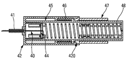
図7の断面図は、退避リング42のスナップ留めタブ420の機能を示すために、図6に対して45°回転させている。
The cross-sectional view of FIG. 7 has been rotated 45 ° relative to FIG. 6 to show the function of the
SMAアクチュエータ49(図7には図示せず)を、その収縮が最大収縮の100%に到達するまでジュール加熱により作動させると、アクチュエータリング47が退避リング42のスナップ留めタブ420に向かって移動する。
Actuating SMA actuator 49 (not shown in FIG. 7) by Joule heating until its contraction reaches 100% of maximum contraction causes
図示の実施形態では、この動きにより退避リング42のスナップ留めタブ420が変形して穿刺リング45が解放される。
In the illustrated embodiment, this movement deforms the snap-
スナップ留めタブ420が解放されて退避バネ46が伸張して、穿刺リング45と、針支持部44および注射針40が相互に連結したアセンブリとが作動する。
The snap-on
この動作により注射針40はユーザの体から退避する。
By this operation, the
有利には、アクチュエータワイヤ49の作動が停止したら、機構はそのままの位置に留まる。
Advantageously, the mechanism remains in place when the
注射針の挿入が完了したら、注射機構が作動する。 When the insertion of the injection needle is completed, the injection mechanism is activated.
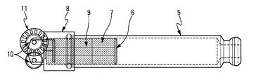
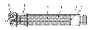
図示の実施形態に係る注射機構は、膨張性材料を含むアクチュエータキャップ7と、アクチュエータ本体8と、加熱手段9とを備える。加熱手段9は、具体的には、ジュール効果を利用したワイヤであり、リール10に巻き付けられている。
The injection mechanism according to the illustrated embodiment includes an actuator cap 7 containing an expandable material, an
図示の実施形態に係る注射機構は、リール10の変位角を測定するための光学式エンコーダのような装置11をさらに備える。
The injection mechanism according to the illustrated embodiment further comprises a
流体投与の主な動力は、アクチュエータキャップ7の材料の体積膨張によって容器5に生じる圧力である。
The main power of fluid administration is the pressure generated in the
動作モードは以下のように説明できる。 The operation mode can be explained as follows.
1)休止時、アクチュエータキャップ7は、容器5の縁に固定されたアクチュエータ本体8に保持されている。アクチュエータ本体8は、加熱ワイヤ9が部分的に巻き付けられている2つのリール10およびエンコーダ11を支持している。加熱ワイヤ9は、アクチュエータキャップ7を通ってアクチュエータ本体8の内部に伸張して、容器5のピストン6に固定されている。
1) At rest, the actuator cap 7 is held by the
2)電流の供給により加熱ワイヤ9を加熱する。アクチュエータの内部温度が一般的には60℃〜90℃の範囲で均一になるように、加熱ワイヤ9は十分に間隔を空けて配置されている。アクチュエータの内部温度がこの範囲に到達すると、アクチュエータキャップ7の材料の体積が著しく膨張する。 2) The heating wire 9 is heated by supplying an electric current. The heating wires 9 are sufficiently spaced so that the internal temperature of the actuator is generally uniform in the range of 60 ° C to 90 ° C. When the internal temperature of the actuator reaches this range, the volume of the material of the actuator cap 7 significantly expands.
3)アクチュエータキャップ7の材料の体積膨張により、ピストン6は容器5の長さに沿って移動する。加熱ワイヤ9は、回転自在なリール10から送り出され得るものであるが、ピストン6の移動により張力を受ける。さらにこの機構により、膨張性材料を含むアクチュエータキャップ7の膨張した部分の全体が加熱され続けるので、アクチュエータキャップ7の膨張を保持できる。
3) The volume expansion of the material of the actuator cap 7 causes the
4)アクチュエータの内部温度およびこれに関連する膨張は、供給電流の制御により調整される。エンコーダ11により測定されたピストン6の動きを監視してこの調整が決定される。容器5から十分な流体が投与されると、供給電流が遮断されて処置が終了する。
4) The internal temperature of the actuator and its associated expansion are regulated by controlling the supply current. This adjustment is determined by monitoring the movement of the
アクチュエータキャップ7の体積を熱刺激によって膨張させる一つの手段としては、熱膨張性微小球体の使用が挙げられる。熱膨張性微小球体とは、炭化水素を封入した中空の熱可塑性微小球体(直径約12マイクロメートル(μm))である。 One means for expanding the volume of the actuator cap 7 by thermal stimulation is the use of thermally expandable microspheres. The heat-expandable microspheres are hollow thermoplastic microspheres (diameter: about 12 micrometers (μm)) in which hydrocarbons are enclosed.
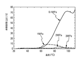
封入液体は飽和炭化水素であり、60℃〜90℃の温度範囲に加熱されて膨張して気相に変態する。封入媒体は、加熱作用により軟化する熱可塑性物質であり、熱可塑性微小球体を熱膨張させて元の体積の5倍〜70倍になる(Y.Nishiyama、U.NobuyukiおよびC.Sato、「熱膨張性粒子を含む分解可能な接着剤の分解挙動および強度」、Int.J.Adhesion&Adhesives、2003年、第23巻、第5刷、p.377−382)。ここで、1メガパスカル(MPa)の外部圧力下で総体積が9倍膨張するので、ピストン6は、元の長さが5mmのアクチュエータキャップ7から45mm移動する。
The enclosed liquid is a saturated hydrocarbon, which is heated to a temperature range of 60 ° C. to 90 ° C., expands and transforms into a gas phase. The encapsulation medium is a thermoplastic substance that is softened by a heating action, and thermally expands the thermoplastic microspheres to be 5 times to 70 times the original volume (Y. Nishiyama, U. Nobuyuki and C. Sato, "Thermal"). Behavior and Strength of Degradable Adhesive Containing Expandable Particles ", Int. J. Adhesion & Adhesives, 2003, Volume 23, Fifth Edition, pp. 377-382). Here, since the total volume expands 9 times under an external pressure of 1 megapascal (MPa), the
アクチュエータのストロークの終わりに加熱が停止される。膨張した微小球体の収縮を防止できるように、炭化水素を封入した熱可塑性材料の係数が上昇する。これは、アクチュエータのストロークを再利用できないことを意味する。 Heating is stopped at the end of the actuator stroke. The modulus of the hydrocarbon-encapsulated thermoplastic material increases so as to prevent contraction of the expanded microspheres. This means that the stroke of the actuator cannot be reused.
炭化水素を封入した微小球体は、例えばアクゾノーベル(スウェーデン)や松本油脂製薬株式会社(日本)などの供給業者から充填剤として入手可能である。 Hydrocarbon-encapsulated microspheres are available as fillers from suppliers such as Akzo Nobel (Sweden) and Matsumoto Yushi-Seiyaku Co., Ltd. (Japan).
図13に、炭化水素を封入した微小球体について、外部圧力を変えて測定した体積膨張比のグラフを示す(出典:Nishiyamaら、2003年)。 FIG. 13 shows a graph of volume expansion ratios of hydrocarbon-encapsulated microspheres measured under different external pressures (Source: Nishiyama et al., 2003).
図12に、アクゾノーベルのエクスパンセル(登録商標)シリーズから入手可能な微小球体の説明を示す(出典:アクゾノーベル、エクスパンセル(登録商標)微小球体概論)。 Figure 12 shows a description of the microspheres available from AkzoNobel's Expancel (R) series (Source: AkzoNobel, Expansell (R) microsphere overview).
注射処置が終了すると、穿刺アクチュエータ8は注射針を装置に退避させる。例えば駆動機構7が拡張しきったら、機械監視および/またはソフトウェア監視により処置の終了を確認できる。
When the injection procedure is completed, the
図1に示す実施形態に係る装置は容器5を3つ含む。3つの駆動機構7は、同時に作動して、それぞれに対応する容器5から同時に流体を投与させることができる。このようにすれば、注射針40の上流で容器5それぞれの流体が混合する。変形例として、3つの駆動機構7は連続的に作動して、それぞれに対応する容器5から連続的に流体を投与させてもよい。また、連続的な作動は独立して行ってもよいが、単一の作動で自動的に投与シーケンスを行ってもよい。この2つの変形例を組み合わせることも可能である。例えば、投与を二段階で行うことである。具体的には、まずは1つの容器の流体が投与され、次に残りの2つの容器の流体が混合して同時に投与される。
The device according to the embodiment shown in FIG. 1 comprises three
装置に容器を複数含むことにより得られる利点を以下に詳述する。 The advantages obtained by including multiple containers in the device are detailed below.
2種類以上の流体を、異なる量であっても、単一の装置で投与できること。 The ability to administer two or more fluids, even in different amounts, in a single device.
2種類以上の流体を併用または混合して投与できること。 Be able to administer two or more fluids together or in combination.
流体に鎮痛薬(麻酔薬や酸中和薬など)を組み合わせて投与できること。 The ability to administer analgesics (such as anesthetics and acid neutralizers) in combination with fluid.
装置の開発コストを削減できること。 The development cost of the device can be reduced.
流体の処方を調節できること。 The ability to control the fluid formulation.
各種の流体を単一の装置に収容できること。 The ability to contain various fluids in a single device.
注射回数を削減できること。 The number of injections can be reduced.
本発明について、好適な実施形態に基づいて説明したが、当然ながら当業者は、添付の特許請求の範囲において定義した本発明の範囲を逸脱しない限りにおいて、任意の変形を適用可能である。 Although the present invention has been described based on the preferred embodiments, those skilled in the art can of course apply any modifications without departing from the scope of the invention as defined in the appended claims.
Claims (11)
注射部位に接触するための支持体(2)に固定された本体(1)と、
前記注射部位を突き刺すための注射針(40)および形状記憶合金からなる穿刺アクチュエータ(49)を含む針アセンブリ(4)と、
注射機構(7,8,9,10,11)と
を備え、
前記本体(1)は流体が入れられた1以上の容器(5)を含み、
前記容器(5)はその内部に注射ピストン(6)を有し、
前記注射機構は、
退避リング(42)と、
針支持部(44)と、
前記穿刺アクチュエータ(49)の一端が固定された穿刺リング(45)と、
退避バネ(46)と、
アクチュエータリング(47)と、
穿刺バネ(48)と
を含み、
前記穿刺バネ(48)および退避バネ(46)は、休止時はそれぞれに対応する阻止手段により圧縮された状態で保持されており、
前記穿刺アクチュエータ(49)を、その収縮が最大収縮の50%に到達するまで加熱により作動させると、
前記アクチュエータリング(47)が前記穿刺リング(45)に対して移動することによって、前記針支持部(44)が解放されて前記穿刺バネ(48)が伸張して、前記注射針(40)が前記注射部位に挿入し、
前記穿刺アクチュエータ(49)を、その収縮が最大収縮の100%に到達するまで加熱により作動させると、
前記アクチュエータリング(47)が前記退避リング(42)に対して移動することによって、前記穿刺リング(45)と、前記針支持部(44)および前記注射針(40)が相互に連結したアセンブリとが解放されて、前記退避バネ(46)が前記注射針(40)を前記注射部位から退避させる
ことを特徴とする自動流体注入装置。 An automatic fluid injection device,
A body (1) fixed to a support (2) for contacting the injection site,
A needle assembly (4) including a needle (40) for piercing the injection site and a puncture actuator (49) made of a shape memory alloy;
With injection mechanism (7,8,9,10,11),
Said body (1) comprises one or more containers (5) containing a fluid,
The container (5) has an injection piston (6) therein,
The injection mechanism is
A withdrawal ring (42),
A needle support (44),
A puncture ring (45) to which one end of the puncture actuator (49) is fixed;
A retracting spring (46),
An actuator ring (47),
Including a puncture spring (48),
The puncture spring (48) and the retracting spring (46) are held in a compressed state by corresponding blocking means at rest,
When the puncture actuator (49) is actuated by heating until its contraction reaches 50% of maximum contraction,
By moving the actuator ring (47) with respect to the puncture ring (45), the needle support part (44) is released, the puncture spring (48) is extended, and the injection needle (40) is moved. Inserted at the injection site,
When the puncture actuator (49) is activated by heating until its contraction reaches 100% of maximum contraction,
Movement of the actuator ring (47) relative to the retraction ring (42) results in the puncture ring (45) and an assembly in which the needle support (44) and the injection needle (40) are interconnected. The automatic fluid injection device characterized in that the retraction spring (46) retracts the injection needle (40) from the injection site when the injection needle (40) is released.
ことを特徴とする請求項1に記載の自動流体注入装置。 The automatic fluid injection device according to claim 1, wherein the puncture actuator (49) is a wire, preferably a wire made of a nickel-titanium alloy (Nitinol).
ことを特徴とする請求項2に記載の自動流体注入装置。 The automatic fluid injection device according to claim 2, wherein the wire (49) is transformed into a martensite phase by heating, and its physical dimension, specifically, its length is changed.
膨張性材料を含むアクチュエータキャップ(7)と、
前記膨張性材料を加熱して膨張させて、前記注射ピストン(6)を前記容器(5)の内部で移動させることにより、前記注射針(40)から前記流体を前記注射部位に注入させる加熱手段(9)と
を含む
ことを特徴とする請求項1〜3のいずれか1項に記載の自動流体注入装置。 The injection mechanism is
An actuator cap (7) comprising an expandable material,
Heating means for injecting the fluid from the injection needle (40) into the injection site by heating and expanding the expandable material to move the injection piston (6) inside the container (5). (9) is included, The automatic fluid injection apparatus of any one of Claims 1-3 characterized by the above-mentioned.
ことを特徴とする請求項4に記載の自動流体注入装置。 The automatic fluid injection device according to claim 4, wherein the expandable material includes heat-expandable microspheres.
ことを特徴とする請求項5に記載の自動流体注入装置。 The automatic fluid injection device according to claim 5, wherein the heat-expandable microspheres include hollow thermoplastic microspheres enclosing a hydrocarbon.
ことを特徴とする請求項6に記載の自動流体注入装置。 When the thermoplastic microspheres are heated to a temperature range of 60 ° C. to 90 ° C., expand and transform into a gas phase, the thermal expandable microspheres expand to 5 times to 70 times the original volume. 7. The automatic fluid injection device of claim 6, wherein
ことを特徴とする請求項1〜7のいずれか1項に記載の自動流体注入装置。 8. Automatic fluid injection device according to any one of the preceding claims, characterized in that the support (2) has a sticker for fixing it to the injection site.
ことを特徴とする請求項1〜8のいずれか1項に記載の自動流体注入装置。 Automatic fluid injection according to any one of the preceding claims, characterized in that the volume of fluid contained in each of said vessels (5) is in the range 1mL-10mL, preferably about 3mL. apparatus.
ことを特徴とする請求項1〜9のいずれか1項に記載の自動流体注入装置。 10. Automatic fluid injection device according to any one of the preceding claims, characterized in that the number of containers (5) is plural, preferably three.
ことを特徴とする請求項1〜10のいずれか1項に記載の自動流体注入装置。 The automatic fluid injection device according to any one of claims 1 to 10, further comprising a power supply means, preferably an optional rechargeable battery.
Applications Claiming Priority (3)
| Application Number | Priority Date | Filing Date | Title |
|---|---|---|---|
| FR1753096A FR3064920B1 (en) | 2017-04-10 | 2017-04-10 | AUTOMATIC FLUID PRODUCT INJECTION DEVICE. |
| FR1753096 | 2017-04-10 | ||
| PCT/FR2018/050863 WO2018189462A1 (en) | 2017-04-10 | 2018-04-06 | Automatic fluid product injection device |
Publications (2)
| Publication Number | Publication Date |
|---|---|
| JP2020512925A true JP2020512925A (en) | 2020-04-30 |
| JP7059352B2 JP7059352B2 (en) | 2022-04-25 |
Family
ID=58739257
Family Applications (1)
| Application Number | Title | Priority Date | Filing Date |
|---|---|---|---|
| JP2020504451A Active JP7059352B2 (en) | 2017-04-10 | 2018-04-06 | Automatic fluid injection device |
Country Status (6)
| Country | Link |
|---|---|
| US (1) | US11229739B2 (en) |
| EP (1) | EP3609557B1 (en) |
| JP (1) | JP7059352B2 (en) |
| CN (1) | CN110691618B (en) |
| FR (1) | FR3064920B1 (en) |
| WO (1) | WO2018189462A1 (en) |
Families Citing this family (6)
| Publication number | Priority date | Publication date | Assignee | Title |
|---|---|---|---|---|
| ATE480278T1 (en) | 2005-09-12 | 2010-09-15 | Unomedical As | INTRODUCTION SYSTEM FOR AN INFUSION SET WITH A FIRST AND SECOND SPRING UNIT |
| US10194938B2 (en) | 2011-03-14 | 2019-02-05 | UnoMedical, AS | Inserter system with transport protection |
| CA3141608A1 (en) | 2019-05-20 | 2020-11-26 | Unomedical A/S | Rotatable infusion device and methods thereof |
| US11191626B1 (en) | 2020-08-17 | 2021-12-07 | Herddogg, Inc. | Tag based administration of pharmaceutical agents to livestock |
| CA3216453A1 (en) | 2021-04-23 | 2022-10-27 | Unomedical A/S | Miniaturized patch pump system |
| EP4456951A4 (en) * | 2021-12-29 | 2025-09-10 | Tandem Diabetes Care Inc | INFUSION PUMPS AND METHODS USING SHAPE MEMORY WIRE-DRIVEN SYRINGE MECHANISM |
Citations (4)
| Publication number | Priority date | Publication date | Assignee | Title |
|---|---|---|---|---|
| JP2002537028A (en) * | 1999-02-17 | 2002-11-05 | オーエン マムフォード リミテッド | Improvements on injection devices |
| JP2005530565A (en) * | 2002-06-24 | 2005-10-13 | アルザ・コーポレーシヨン | Reusable spring-driven auto-injector with shape memory alloy drive spring |
| JP2006526446A (en) * | 2003-06-05 | 2006-11-24 | オウエン マンフォード リミティド | Syringe firing mechanism |
| JP2013533069A (en) * | 2010-08-10 | 2013-08-22 | エフ.ホフマン−ラ ロシュ アーゲー | Drug reconstitution and delivery device |
Family Cites Families (7)
| Publication number | Priority date | Publication date | Assignee | Title |
|---|---|---|---|---|
| JPH0451966A (en) * | 1990-06-19 | 1992-02-20 | Toichi Ishikawa | Medical fluid continuous injector |
| US7052251B2 (en) * | 2002-04-22 | 2006-05-30 | Medtronic Minimed, Inc. | Shape memory alloy wire driven positive displacement micropump with pulsatile output |
| ATE498421T1 (en) * | 2002-12-23 | 2011-03-15 | Asante Solutions Inc | FLEXIBLE PISTON ROD |
| WO2005072795A2 (en) * | 2004-01-29 | 2005-08-11 | M 2 Medical A/S | Disposable medicine dispensing device |
| US7905868B2 (en) * | 2006-08-23 | 2011-03-15 | Medtronic Minimed, Inc. | Infusion medium delivery device and method with drive device for driving plunger in reservoir |
| US7828792B2 (en) * | 2008-07-25 | 2010-11-09 | Medasys Incorporated | MRI compatible programmable valve pump |
| JOP20170042B1 (en) * | 2016-02-12 | 2022-09-15 | Amgen Inc | Means of drug delivery, method of manufacture and method of use |
-
2017
- 2017-04-10 FR FR1753096A patent/FR3064920B1/en active Active
-
2018
- 2018-04-06 CN CN201880033529.XA patent/CN110691618B/en active Active
- 2018-04-06 US US16/604,275 patent/US11229739B2/en active Active
- 2018-04-06 EP EP18722122.1A patent/EP3609557B1/en active Active
- 2018-04-06 JP JP2020504451A patent/JP7059352B2/en active Active
- 2018-04-06 WO PCT/FR2018/050863 patent/WO2018189462A1/en not_active Ceased
Patent Citations (4)
| Publication number | Priority date | Publication date | Assignee | Title |
|---|---|---|---|---|
| JP2002537028A (en) * | 1999-02-17 | 2002-11-05 | オーエン マムフォード リミテッド | Improvements on injection devices |
| JP2005530565A (en) * | 2002-06-24 | 2005-10-13 | アルザ・コーポレーシヨン | Reusable spring-driven auto-injector with shape memory alloy drive spring |
| JP2006526446A (en) * | 2003-06-05 | 2006-11-24 | オウエン マンフォード リミティド | Syringe firing mechanism |
| JP2013533069A (en) * | 2010-08-10 | 2013-08-22 | エフ.ホフマン−ラ ロシュ アーゲー | Drug reconstitution and delivery device |
Also Published As
| Publication number | Publication date |
|---|---|
| FR3064920B1 (en) | 2020-08-21 |
| US11229739B2 (en) | 2022-01-25 |
| CN110691618B (en) | 2022-04-12 |
| WO2018189462A1 (en) | 2018-10-18 |
| CN110691618A (en) | 2020-01-14 |
| EP3609557A1 (en) | 2020-02-19 |
| US20200114064A1 (en) | 2020-04-16 |
| JP7059352B2 (en) | 2022-04-25 |
| EP3609557B1 (en) | 2024-06-05 |
| FR3064920A1 (en) | 2018-10-12 |
Similar Documents
| Publication | Publication Date | Title |
|---|---|---|
| JP7059352B2 (en) | Automatic fluid injection device | |
| JP7089018B2 (en) | Automatic fluid injection device | |
| KR102689702B1 (en) | Systems and methods for controlling drug delivery pumps | |
| JP4911897B2 (en) | Reusable spring-driven auto-injector with shape memory alloy drive spring | |
| JP5311685B2 (en) | Device for delivering drugs | |
| US11311670B2 (en) | Automatic injection device having a passive drive system with a shape memory spring | |
| JP6814809B2 (en) | Automatic syringe with needle shield activation | |
| EP3125975B1 (en) | Autoinjector having needle shield triggering | |
| JP6130377B2 (en) | Insertion mechanism for drug delivery pump | |
| JP6303086B2 (en) | Drive mechanism for drug delivery pump with built-in status indication | |
| JP2019150627A (en) | Sterilization fluid path connecting part for medicine container for medicine delivery pump | |
| CN110325232A (en) | Automatic injection device for fluid product | |
| US20230398308A1 (en) | Medicament delivery device with piezoelectric actuating system |
Legal Events
| Date | Code | Title | Description |
|---|---|---|---|
| A621 | Written request for application examination |
Free format text: JAPANESE INTERMEDIATE CODE: A621 Effective date: 20210304 |
|
| A977 | Report on retrieval |
Free format text: JAPANESE INTERMEDIATE CODE: A971007 Effective date: 20211124 |
|
| A131 | Notification of reasons for refusal |
Free format text: JAPANESE INTERMEDIATE CODE: A131 Effective date: 20211130 |
|
| A521 | Request for written amendment filed |
Free format text: JAPANESE INTERMEDIATE CODE: A523 Effective date: 20220228 |
|
| TRDD | Decision of grant or rejection written | ||
| A01 | Written decision to grant a patent or to grant a registration (utility model) |
Free format text: JAPANESE INTERMEDIATE CODE: A01 Effective date: 20220315 |
|
| A61 | First payment of annual fees (during grant procedure) |
Free format text: JAPANESE INTERMEDIATE CODE: A61 Effective date: 20220413 |
|
| R150 | Certificate of patent or registration of utility model |
Ref document number: 7059352 Country of ref document: JP Free format text: JAPANESE INTERMEDIATE CODE: R150 |
|
| R250 | Receipt of annual fees |
Free format text: JAPANESE INTERMEDIATE CODE: R250 |
|
| R250 | Receipt of annual fees |
Free format text: JAPANESE INTERMEDIATE CODE: R250 |