JP2021027043A - Method for manufacturing electrode material for lithium ion battery, and device for manufacturing electrode material for lithium ion battery - Google Patents
Method for manufacturing electrode material for lithium ion battery, and device for manufacturing electrode material for lithium ion battery Download PDFInfo
- Publication number
- JP2021027043A JP2021027043A JP2020133299A JP2020133299A JP2021027043A JP 2021027043 A JP2021027043 A JP 2021027043A JP 2020133299 A JP2020133299 A JP 2020133299A JP 2020133299 A JP2020133299 A JP 2020133299A JP 2021027043 A JP2021027043 A JP 2021027043A
- Authority
- JP
- Japan
- Prior art keywords
- electrode composition
- electrode
- base material
- ion battery
- lithium ion
- Prior art date
- Legal status (The legal status is an assumption and is not a legal conclusion. Google has not performed a legal analysis and makes no representation as to the accuracy of the status listed.)
- Pending
Links
Images




Classifications
-
- Y—GENERAL TAGGING OF NEW TECHNOLOGICAL DEVELOPMENTS; GENERAL TAGGING OF CROSS-SECTIONAL TECHNOLOGIES SPANNING OVER SEVERAL SECTIONS OF THE IPC; TECHNICAL SUBJECTS COVERED BY FORMER USPC CROSS-REFERENCE ART COLLECTIONS [XRACs] AND DIGESTS
- Y02—TECHNOLOGIES OR APPLICATIONS FOR MITIGATION OR ADAPTATION AGAINST CLIMATE CHANGE
- Y02E—REDUCTION OF GREENHOUSE GAS [GHG] EMISSIONS, RELATED TO ENERGY GENERATION, TRANSMISSION OR DISTRIBUTION
- Y02E60/00—Enabling technologies; Technologies with a potential or indirect contribution to GHG emissions mitigation
- Y02E60/10—Energy storage using batteries
Landscapes
- Coating Apparatus (AREA)
- Application Of Or Painting With Fluid Materials (AREA)
- Battery Electrode And Active Subsutance (AREA)
Abstract
【課題】電極組成物の流動性が低い場合であっても、集電体上に所定の間隔で均一な電極組成物層を配置できるリチウムイオン電池用電極材の製造方法を提供すること。【解決手段】連続するシート状の基材の表面に、電極活物質を含む電極組成物からなる電極組成物層が配置された電極組成物層配置部が間欠的に配置されたリチウムイオン電池用電極材の製造方法であって、上記基材上に上記電極組成物を連続的に供給する供給工程と、上記供給工程によって上記基材上に供給された上記電極組成物を加圧して上記電極組成物層を得る加圧工程と、上記供給工程によって上記基材上に供給された上記電極組成物の一部を除去して、上記基材上に電極組成物層配置部を形成する除去工程と、を備えることを特徴とするリチウムイオン電池用電極材の製造方法。【選択図】 図1PROBLEM TO BE SOLVED: To provide a method for producing an electrode material for a lithium ion battery, which can arrange uniform electrode composition layers at predetermined intervals on a current collector even when the fluidity of the electrode composition is low. SOLUTION: For a lithium ion battery in which an electrode composition layer arrangement portion in which an electrode composition layer composed of an electrode composition containing an electrode active material is arranged on the surface of a continuous sheet-like base material is intermittently arranged. A method for producing an electrode material, which is a supply step of continuously supplying the electrode composition onto the base material and a pressurization of the electrode composition supplied onto the base material by the supply step to press the electrode. A pressurizing step of obtaining a composition layer and a removing step of removing a part of the electrode composition supplied onto the base material by the supply step to form an electrode composition layer arrangement portion on the base material. A method for manufacturing an electrode material for a lithium ion battery, which comprises. [Selection diagram] Fig. 1
Description
本発明は、リチウムイオン電池用電極材の製造方法及びリチウムイオン電池用電極材の製造装置に関する。 The present invention relates to a method for manufacturing an electrode material for a lithium ion battery and an apparatus for manufacturing an electrode material for a lithium ion battery.
電気自動車及びハイブリッド電気自動車等の電源等に使用できる高エネルギー密度のリチウムイオン電池としては、その用途に応じて円筒型、角型及びラミネート型の電池が用いられており、それに用いられる発電素子は、電極シートとセパレータとを積層することで製造できる。電極シートを製造する方法としては、シート上に活物質を塗工した電極シートを加圧ロール等で加圧した後、所定の長さに切断する方法が知られている(特許文献1参照)。 As a high energy density lithium ion battery that can be used as a power source for electric vehicles and hybrid electric vehicles, cylindrical, square, and laminated batteries are used depending on the application, and the power generation element used for the lithium ion battery is , It can be manufactured by laminating an electrode sheet and a separator. As a method for producing an electrode sheet, a method is known in which an electrode sheet coated with an active material on the sheet is pressed with a pressure roll or the like and then cut to a predetermined length (see Patent Document 1). ..
しかしながら、特許文献1に記載された方法は、塗工する電極組成物の流動性が低い場合には適用できないという問題があった。具体的には、電極組成物の流動性が低いために均一な塗膜を形成できない。さらに、加圧された電極組成物は脆いため、電極シートの切断時に割れや欠落が生じる場合がある。これらの理由から、電極シートを電池にした場合に耐久性等の電池性能が充分でない問題があった。 However, the method described in Patent Document 1 has a problem that it cannot be applied when the fluidity of the electrode composition to be coated is low. Specifically, a uniform coating film cannot be formed due to the low fluidity of the electrode composition. Further, since the pressurized electrode composition is brittle, cracks or chips may occur when the electrode sheet is cut. For these reasons, there is a problem that the battery performance such as durability is not sufficient when the electrode sheet is used as a battery.
本発明は、上記課題を鑑みてなされたものであり、電極組成物の流動性が低い場合であっても、集電体上に所定の間隔で均一な電極組成物層を配置できるリチウムイオン電池用電極材の製造方法を提供することを目的とする。 The present invention has been made in view of the above problems, and a lithium ion battery capable of arranging uniform electrode composition layers on a current collector at predetermined intervals even when the fluidity of the electrode composition is low. It is an object of the present invention to provide a method for manufacturing an electrode material for use.
本発明は、連続するシート状の基材の表面に、電極活物質を含む電極組成物からなる電極組成物層が配置された電極組成物層配置部が間欠的に配置されたリチウムイオン電池用電極材の製造方法であって、上記基材上に上記電極組成物を連続的に供給する供給工程と、上記供給工程によって上記基材上に供給された上記電極組成物を加圧して上記電極組成物層を得る加圧工程と、上記供給工程によって上記基材上に供給された上記電極組成物の一部を除去して、上記基材上に電極組成物層配置部を形成する除去工程と、を備えることを特徴とするリチウムイオン電池用電極材の製造方法、及び、連続するシート状の基材の表面に、電極活物質を含む電極組成物からなる電極組成物層が配置された電極組成物層配置部が間欠的に配置されたリチウムイオン電池用電極材の製造装置であって、上記基材上に上記電極組成物を連続的に供給する供給手段と、上記供給手段によって上記基材上に供給された上記電極組成物を加圧して上記電極組成物層を得る加圧手段と、上記供給手段によって上記基材上に供給された上記電極組成物の一部を除去して、上記基材上に電極組成物層配置部を形成する除去手段と、を備えることを特徴とするリチウムイオン電池用電極材の製造装置に関する。 The present invention is for a lithium ion battery in which an electrode composition layer arrangement portion in which an electrode composition layer composed of an electrode composition containing an electrode active material is arranged intermittently on the surface of a continuous sheet-like base material. A method for producing an electrode material, wherein the electrode composition is continuously supplied onto the base material, and the electrode composition supplied onto the base material is pressurized by the supply step to pressurize the electrode. A pressurizing step of obtaining a composition layer and a removing step of removing a part of the electrode composition supplied onto the base material by the supply step to form an electrode composition layer arrangement portion on the base material. An electrode composition layer composed of an electrode composition containing an electrode active material is arranged on the surface of a continuous sheet-shaped base material and a method for producing an electrode material for a lithium ion battery. An apparatus for producing an electrode material for a lithium ion battery in which an electrode composition layer arranging portion is intermittently arranged, wherein the electrode composition is continuously supplied onto the base material, and the supply means is used. The pressurizing means for pressurizing the electrode composition supplied on the base material to obtain the electrode composition layer and a part of the electrode composition supplied on the base material by the supply means are removed. The present invention relates to an apparatus for producing an electrode material for a lithium ion battery, which comprises a removing means for forming an electrode composition layer arrangement portion on the base material.
本発明のリチウムイオン電池用電極材の製造方法は、電極組成物の流動性が低い場合であっても、集電体上に所定の間隔で均一な電極組成物層を配置できるリチウムイオン電池用電極材を提供することができる。 The method for producing an electrode material for a lithium ion battery of the present invention is for a lithium ion battery in which uniform electrode composition layers can be arranged on a current collector at predetermined intervals even when the fluidity of the electrode composition is low. An electrode material can be provided.
以下、本発明を詳細に説明する。
なお、本明細書において、リチウムイオン電池と記載する場合、リチウムイオン二次電池も含む概念とする。
Hereinafter, the present invention will be described in detail.
In the present specification, when the term lithium ion battery is used, the concept includes a lithium ion secondary battery.
[リチウムイオン電池用電極材]
まず、本発明のリチウムイオン電池用電極材の製造方法により得られるリチウムイオン電池用電極材について説明する。
本発明のリチウムイオン電池用電極材の製造方法により得られるリチウムイオン電池用電極材は、連続するシート状の基材の表面に電極活物質を含む電極組成物からなる電極組成物層が配置された電極組成物層配置部が間欠的に配置されている。
ここで、連続するシート状の基材の表面に電極組成物層配置部が間欠的に配置されているとは、1つの基材の表面に、電極組成物層配置部と、電極組成物層が配置されていない部分(電極組成物層非配置部)とが存在し、電極組成物層配置部が2個以上存在し、かつ、互いに接触していない状態を意味する。互いに接触しないように設けられた電極組成物層配置部同士の距離は、一定であってもよく、異なっていてもよい。
[Electrode material for lithium-ion batteries]
First, the electrode material for a lithium ion battery obtained by the method for producing an electrode material for a lithium ion battery of the present invention will be described.
In the electrode material for a lithium ion battery obtained by the method for producing an electrode material for a lithium ion battery of the present invention, an electrode composition layer composed of an electrode composition containing an electrode active material is arranged on the surface of a continuous sheet-like base material. The electrode composition layer arrangement portion is intermittently arranged.
Here, the fact that the electrode composition layer arrangement portion is intermittently arranged on the surface of the continuous sheet-like base material means that the electrode composition layer arrangement portion and the electrode composition layer are arranged on the surface of one base material. It means that there is a portion where the electrode composition layer is not arranged (the electrode composition layer non-arranged portion), two or more electrode composition layer-arranged portions are present, and the electrodes are not in contact with each other. The distance between the electrode composition layer arrangement portions provided so as not to come into contact with each other may be constant or different.
電極組成物層配置部に配置された電極組成物層は、集電体上に配置されることによって、リチウムイオン電池用の電極として機能する。従って、基材が集電体である場合には、リチウムイオン電池用電極材をリチウムイオン電池用電極として用いることができる。一方、基材が集電体ではない場合には、電極組成物層を集電体上に移すことで、リチウムイオン電池用電極を得ることができる。 The electrode composition layer arranged in the electrode composition layer arrangement portion functions as an electrode for a lithium ion battery by being arranged on the current collector. Therefore, when the base material is a current collector, the electrode material for the lithium ion battery can be used as the electrode for the lithium ion battery. On the other hand, when the base material is not a current collector, the electrode for a lithium ion battery can be obtained by moving the electrode composition layer onto the current collector.
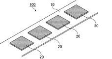
本発明のリチウムイオン電池用電極材の製造方法により得られるリチウムイオン電池用電極材の例について、図1を参照しながら説明する。
図1は、本発明のリチウムイオン電池用電極材の製造方法により製造されるリチウムイオン電池用電極材の一例を模式的に示す斜視図である。
図1に示すように、リチウムイオン電池用電極材100では、連続するシート状の基材10の表面に、電極活物質を含む電極組成物からなる電極組成物層20が配置された電極組成物層配置部が、間欠的に配置されている。
基材10の表面のうち、電極組成物層20が配置された領域(電極組成物層配置部)以外の領域を電極組成物層非配置部ともいう。
リチウムイオン電池用電極材100では、電極組成物層20が配置された電極組成物層配置部が電極組成物層非配置部に囲まれた島状であり、電極組成物層非配置部と島状の電極組成物層配置部とが交互に配置されているともいえる。
本発明のリチウムイオン電池用電極材の製造方法により得られるリチウムイオン電池用電極材を、基材の長手方向に沿った方向、かつ、基材の厚さ方向に垂直な方向に切断した切断面からみた場合には、電極組成物層配置部と電極組成物層非配置部とが交互に配置されていることになる。
An example of the electrode material for a lithium ion battery obtained by the method for producing an electrode material for a lithium ion battery of the present invention will be described with reference to FIG.
FIG. 1 is a perspective view schematically showing an example of an electrode material for a lithium ion battery manufactured by the method for manufacturing an electrode material for a lithium ion battery of the present invention.
As shown in FIG. 1, in the
Of the surface of the
In the
A cut surface obtained by cutting the electrode material for a lithium ion battery obtained by the method for producing an electrode material for a lithium ion battery of the present invention in a direction along the longitudinal direction of the base material and in a direction perpendicular to the thickness direction of the base material. When viewed from the perspective, the electrode composition layer-arranged portions and the electrode composition layer-non-arranged portions are alternately arranged.
図1に示すリチウムイオン電池用電極材100では、基材10の幅方向の両端部に、電極組成物層が設けられていない領域が存在するが、本発明のリチウムイオン電池用電極材においては、基材の幅方向の端部にまで電極組成物層が配置されていてもよい。この場合、電極組成物層が配置された電極組成物層配置部と電極組成物層非配置部とがそれぞれ縞状に配置されているともいえる。
In the
本発明の製造方法で得られるリチウムイオン電池用電極材を用いてリチウムイオン電池を製造する際には、必要に応じて、基材を切断して、電極組成物層配置部を分離する。このとき、基材を切断する位置を、電極組成物層非配置部とすることによって、電極組成物層配置部を切断する必要がなくなり、電極組成物層に割れや欠落等が生じにくい。その結果、耐久性等の電池性能に優れたリチウムイオン電池を製造することができる。 When manufacturing a lithium ion battery using the electrode material for a lithium ion battery obtained by the manufacturing method of the present invention, if necessary, the base material is cut to separate the electrode composition layer arrangement portion. At this time, by setting the position where the base material is cut to the non-arranged portion of the electrode composition layer, it is not necessary to cut the arranged portion of the electrode composition layer, and the electrode composition layer is less likely to be cracked or chipped. As a result, a lithium ion battery having excellent battery performance such as durability can be manufactured.
[リチウムイオン電池用電極材の製造方法]
本発明は、連続するシート状の基材の表面に、電極活物質を含む電極組成物からなる電極組成物層が配置された電極組成物層配置部が間欠的に配置されたリチウムイオン電池用電極材の製造方法であって、上記基材上に上記電極組成物を連続的に供給する供給工程と、上記供給工程によって上記基材上に供給された上記電極組成物を加圧して上記電極組成物層を得る加圧工程と、上記供給工程によって上記基材上に供給された上記電極組成物の一部を除去して、上記基材上に電極組成物層配置部を形成する除去工程と、を備えることを特徴とする。
[Manufacturing method of electrode material for lithium-ion batteries]
The present invention is for a lithium ion battery in which an electrode composition layer arrangement portion in which an electrode composition layer composed of an electrode composition containing an electrode active material is arranged intermittently on the surface of a continuous sheet-like base material. A method for producing an electrode material, wherein the electrode composition is continuously supplied onto the base material, and the electrode composition supplied onto the base material is pressurized by the supply step to pressurize the electrode. A pressurizing step of obtaining a composition layer and a removing step of removing a part of the electrode composition supplied onto the base material by the supply step to form an electrode composition layer arrangement portion on the base material. It is characterized by having.
本発明のリチウムイオン電池用電極材の製造方法においては、除去工程と加圧工程の順序は特に限定されない。従って、除去工程を行ってから加圧工程を行ってもよいし、加圧工程を行ってから除去工程を行ってもよい。また、加圧工程と除去工程を同時に行ってもよい。以下には、まず除去工程を行い、その後加圧工程を行う場合を説明する。 In the method for producing an electrode material for a lithium ion battery of the present invention, the order of the removal step and the pressurization step is not particularly limited. Therefore, the removing step may be performed and then the pressurizing step may be performed, or the pressurizing step may be performed and then the removing step may be performed. Further, the pressurizing step and the removing step may be performed at the same time. The case where the removing step is first performed and then the pressurizing step is performed will be described below.
[供給工程]
供給工程では、連続するシート状の基材上に電極活物質を含む電極組成物を連続的に供給する。
連続的に供給する、とは、後述する除去工程によって形成される2以上の電極組成物層配置部に跨るように、電極組成物を途切れないように供給することを意味する。この時、電極組成物を間欠的に供給してもよい。ただし、電極組成物を間欠的に供給する場合、電極組成物を間欠的に供給することで基材上に形成された電極組成物を、後述する除去工程によって2以上の電極組成物層配置部とする必要がある。従って、間欠的に供給された1つの電極組成物に1つの電極組成物層配置部しか形成しない場合は、基材上に電極組成物を連続的に供給しているとはいえない。
また連続するシート状とは、単一の基材上に、複数個の電極組成物層配置部を間欠的に配置するのに充分な長さを有していることを意味する。
また基材上に供給するとは、基材の表面に直接供給するだけでなく、基材の上に配置された別の部材上に電極組成物を供給する場合も含む。従って、供給工程では、基材上に、直接又は間接的に電極組成物を供給する。
[Supply process]
In the supply step, the electrode composition containing the electrode active material is continuously supplied on a continuous sheet-like base material.
Continuously supplying means that the electrode composition is supplied without interruption so as to straddle two or more electrode composition layer arrangement portions formed by the removal step described later. At this time, the electrode composition may be supplied intermittently. However, when the electrode composition is intermittently supplied, the electrode composition formed on the base material by intermittently supplying the electrode composition is removed by two or more electrode composition layer arrangement portions by a removal step described later. Must be. Therefore, when only one electrode composition layer arrangement portion is formed in one intermittently supplied electrode composition, it cannot be said that the electrode composition is continuously supplied on the base material.
Further, the continuous sheet shape means having a sufficient length for intermittently arranging a plurality of electrode composition layer arranging portions on a single base material.
Further, the supply on the base material includes not only the case where the electrode composition is directly supplied to the surface of the base material but also the case where the electrode composition is supplied on another member arranged on the base material. Therefore, in the supply step, the electrode composition is directly or indirectly supplied onto the substrate.
基材上に供給された電極組成物の厚さは、必要に応じて調整してもよい。
電極組成物の厚さを調整する方法としては、スキージ、回転ローラ、ドクターブレード、アプリケータ等を用いる方法が挙げられる。電極組成物の厚さを調整する工程は、上述した供給工程において用いられる装置によって行われてもよく、供給工程において用いられる装置とは別の装置を用いて行われてもよい。
The thickness of the electrode composition supplied on the substrate may be adjusted if necessary.
Examples of the method for adjusting the thickness of the electrode composition include a method using a squeegee, a rotating roller, a doctor blade, an applicator and the like. The step of adjusting the thickness of the electrode composition may be carried out by an apparatus used in the above-mentioned supply step, or may be carried out by using an apparatus different from the apparatus used in the supply step.
供給工程の一例について、図2を参照しながら説明する。
図2は、供給工程の一例を模式的に示す断面図である。
図2に示すように、供給工程では、シート状の基材10上に、電極組成物120を連続的に供給する。具体的には、定量的に電極組成物120を供給可能なホッパー110と基材10との相対位置を変化させながら、基材10上に配置されたホッパー110から、電極組成物120を連続的に供給する方法を用いることができる。
An example of the supply process will be described with reference to FIG.
FIG. 2 is a cross-sectional view schematically showing an example of a supply process.
As shown in FIG. 2, in the supply step, the
ホッパー110と基材10との相対位置を変化させる方法は特に限定されず、ベルトコンベヤによって基材10を一方向に移動させてもよい。また、ホッパー110に車輪を設け、車輪を駆動させる方法や、ホッパー110をウインチにより一方向に巻き取る方法等であってもよい。
The method of changing the relative positions of the
なお、ホッパー110は、後述する本発明のリチウムイオン電池用電極材の製造装置における供給手段に相当する。
The
ホッパーと基材との相対位置の変化速度は、電極組成物層の密度や厚さ、及び電極組成物層の粘度により適宜調整することができる。 The rate of change in the relative position between the hopper and the base material can be appropriately adjusted by adjusting the density and thickness of the electrode composition layer and the viscosity of the electrode composition layer.
供給工程の別の一例について、図3を参照しながら説明する。
図3は、供給工程の別の一例を模式的に示す断面図である。
図3に示すように、供給工程では、シート状の基材10上に、定量供給装置(図示しない)によって電極組成物120Aを間欠的に供給する。間欠的に供給された電極組成物120Aは、基材10とスキージ130との間を通過することによって、厚さが調整され、電極組成物120Bとなる。
1つの電極組成物120Bは、後に除去工程を行うことで、2以上の電極組成物層配置部となる。すなわち、図3に示す供給工程では、後の除去工程において形成される2以上の電極組成物層配置部に跨るように電極組成物を供給しているため、電極組成物を連続的に供給しているといえる。
Another example of the supply process will be described with reference to FIG.
FIG. 3 is a cross-sectional view schematically showing another example of the supply process.
As shown in FIG. 3, in the supply step, the
One
なお、ホッパー及び必要に応じて用いるスキージは、後述する本発明のリチウムイオン電池用電極材の製造装置における供給手段に相当する。 The hopper and the squeegee used as needed correspond to the supply means in the apparatus for manufacturing the electrode material for a lithium ion battery of the present invention, which will be described later.
基材としては、構成材料は特に限定されない。基材として集電体そのものを用いてもよい。基材が集電体ではない場合には、基材の表面に形成した電極組成物層を基材から剥離できるものであればよい。なお、基材として集電体を用いる場合、電極組成物層を剥離する必要はない。
集電体としては、金属箔や導電性樹脂箔等が挙げられる。
集電体以外の基材としては、集電体としては機能しないシート状の材料[高分子フィルム(ポリエステルフィルム、ポリオレフィンシート及びテフロン(登録商標)シート等)及び紙等]等を用いることができる。
また、基材は複合材料であってもよい。基材が複合材料である場合の例としては、集電体と、該集電体の外周に沿って環状に配置された絶縁体(枠状部材ともいう)を有する枠付き集電体等が挙げられる。
The constituent material is not particularly limited as the base material. The current collector itself may be used as the base material. When the base material is not a current collector, the electrode composition layer formed on the surface of the base material may be peeled off from the base material. When a current collector is used as the base material, it is not necessary to peel off the electrode composition layer.
Examples of the current collector include metal foil and conductive resin foil.
As the base material other than the current collector, a sheet-like material [polymer film (polyester film, polyolefin sheet, Teflon (registered trademark) sheet, etc.), paper, etc.] that does not function as a current collector can be used. ..
Moreover, the base material may be a composite material. Examples of cases where the base material is a composite material include a current collector and a framed current collector having an insulator (also referred to as a frame-shaped member) arranged in an annular shape along the outer circumference of the current collector. Can be mentioned.
供給工程において用いられる電極組成物については後述する。 The electrode composition used in the feeding process will be described later.
[除去工程]
除去工程では、基材上に供給された電極組成物の一部を除去して、基材上に電極組成物層配置部を形成する。電極組成物層配置部が形成されなかった領域が、電極組成物層非配置部となる。
なお、除去工程よりも後に加圧工程が行われる場合であって、加圧工程によって電極組成物層配置部の大きさが変化する場合には、加圧後に所望の形状となるような電極組成物層配置部の大きさを予め設定しておくことが好ましい。
[Removal process]
In the removing step, a part of the electrode composition supplied on the base material is removed to form an electrode composition layer arrangement portion on the base material. The region where the electrode composition layer arrangement portion is not formed becomes the electrode composition layer non-arrangement portion.
When the pressurization step is performed after the removal step and the size of the electrode composition layer arrangement portion changes due to the pressurization step, the electrode composition has a desired shape after pressurization. It is preferable to set the size of the material layer arrangement portion in advance.
[除去工程の実施形態1]
基材上に供給された電極組成物の一部を除去する方法としては、例えば、供給工程の前に、電極組成物層配置部の配置パターンに応じた位置に開口部を有するマスク層を基材の表面に載置して、供給工程の後に、基材上からマスク層上に供給された電極組成物を除去する方法が挙げられる。
開口部を有するマスク層を基材の表面に載置する工程は、マスキング工程ともいう。
なお、マスク層が有する開口部の位置及び形状は、除去工程によって形成される電極組成物層配置部の位置及び形状に対応している。
[Embodiment 1 of removal step]
As a method of removing a part of the electrode composition supplied on the base material, for example, a mask layer having an opening at a position corresponding to the arrangement pattern of the electrode composition layer arrangement portion is used as a base before the supply step. Examples thereof include a method of placing the electrode composition on the surface of the material and removing the electrode composition supplied onto the mask layer from the base material after the supply step.
The step of placing the mask layer having an opening on the surface of the base material is also referred to as a masking step.
The position and shape of the opening of the mask layer correspond to the position and shape of the electrode composition layer arrangement portion formed by the removing step.
また、本明細書において、電極組成物層配置部の配置パターンとは、電極組成物層配置部の位置、形状、大きさ、及び、複数個の電極組成物層配置部の並び等を含めた、電極組成物層配置部の配置を指す。 Further, in the present specification, the arrangement pattern of the electrode composition layer arrangement portion includes the position, shape, size of the electrode composition layer arrangement portion, the arrangement of a plurality of electrode composition layer arrangement portions, and the like. , Refers to the arrangement of the electrode composition layer arrangement portion.
本発明のリチウムイオン電池用電極材の製造方法が、除去工程の実施形態1を行う場合、除去工程の前に、間欠的に配置された開口部を有するマスク層を基材の表面に載置するマスキング工程を備え、供給工程において、電極組成物を、マスク層上、及び、開口部の全面に供給し、除去工程が、マスク層上に供給された電極組成物を、基材上から除去する工程であることが好ましい。 When the method for producing an electrode material for a lithium ion battery of the present invention performs the first embodiment of the removal step, a mask layer having intermittently arranged openings is placed on the surface of the base material before the removal step. The electrode composition is supplied onto the mask layer and the entire surface of the opening in the supply step, and the removal step removes the electrode composition supplied on the mask layer from the substrate. It is preferable that the process is performed.
除去工程の一例について、図4A及び図4Bを参照しながら説明する。
図4Aは、供給工程の一例を模式的に示す斜視図であり、図4Bは、除去工程の一例を模式的に示す斜視図である。
図4Aに示すように、供給工程の前に、電極組成物層配置部に対応する大きさの開口部(A1、A2、A3、A4及びA5)を有するマスク層140を、基材10上に載置する。
この場合、供給工程では、マスク層140上と、マスク層140の開口部(A1、A2、A3、A4及びA5)の全面に、電極組成物120が供給される。
An example of the removal step will be described with reference to FIGS. 4A and 4B.
FIG. 4A is a perspective view schematically showing an example of a supply process, and FIG. 4B is a perspective view schematically showing an example of a removal process.
As shown in FIG. 4A, prior to the feeding step, a
In this case, in the supply step, the
続いて、図4Bに示すように、除去工程においてマスク層140を基材10から除去する。このとき、マスク層140の開口部の中に配置されている電極組成物120は基材10上に残存することとなる。一方、マスク層140の上に供給された電極組成物120は、マスク層140ごと基材10上から除去される。
マスク層140の開口部(A1、A2、A3、A4及びA5)があった領域だけに電極組成物120が残存することで、基材10上には、電極組成物120が設けられた領域である電極組成物層配置部が間欠的に形成される。
Subsequently, as shown in FIG. 4B, the
The
除去工程の実施形態1では、2段階の除去工程を行ってもよい。
2段階の除去工程とは、例えば、マスク層上に供給された電極組成物の少なくとも一部をマスク層上から除去する第1除去工程と、マスク層を基板上から除去する第2除去工程とが挙げられる。
第1除去工程においてマスク層上の電極組成物を完全に除去していない場合、第2除去工程において、マスク層上に残存する電極組成物をマスク層ごと除去すればよい。
第1除去工程によってマスク層上に供給された電極組成物の少なくとも一部を除去しておくと、マスク層を基板上から除去する第2除去工程の際に、マスク層上に残存する電極組成物が、マスク層の開口部に配置された電極組成物上に落下することを抑制できる。
In the first embodiment of the removal step, a two-step removal step may be performed.
The two-step removal step includes, for example, a first removal step of removing at least a part of the electrode composition supplied on the mask layer from the mask layer, and a second removal step of removing the mask layer from the substrate. Can be mentioned.
When the electrode composition on the mask layer is not completely removed in the first removing step, the electrode composition remaining on the mask layer may be removed together with the mask layer in the second removing step.
If at least a part of the electrode composition supplied on the mask layer is removed by the first removing step, the electrode composition remaining on the mask layer during the second removing step of removing the mask layer from the substrate. It is possible to prevent the object from falling onto the electrode composition arranged in the opening of the mask layer.
マスク層に設けられた開口部は、電極組成物層配置部の配置パターンに応じた位置に複数個設けられている。複数ある開口部の大きさは、各電極組成物層配置部に対応する大きさであれば全て同じであってもよく、異なっていてもよい。また、開口部同士の距離は、全て同じであってもよく、異なっていてもよい。 A plurality of openings provided in the mask layer are provided at positions corresponding to the arrangement pattern of the electrode composition layer arrangement portion. The sizes of the plurality of openings may be the same or different as long as they have a size corresponding to each electrode composition layer arrangement portion. Further, the distances between the openings may be the same or different.
なお、マスク層140は、後述する本発明のリチウムイオン電池用電極材の製造装置における除去手段に相当する。
The
開口部を有するマスク層としては、基材上に分離可能に重ねることができ、かつ間欠的に配置された所定の大きさの開口部を所定の位置に複数有する構造であれば制限なく使用することができ、開口部を有する金属シート及び開口部を有する樹脂フィルム等を使用することができる。
供給工程においてマスク層と基材との間に電極組成物が侵入しないように、マスク層と基材とが一時的に接着されていてもよい。
また、基材から剥離可能な塗膜を形成する塗料を、所定の開口部を残すように基材の表面に塗布して、マスク層を形成してもよい。
The mask layer having openings can be used without limitation as long as it can be separably stacked on the base material and has a plurality of intermittently arranged openings of a predetermined size at predetermined positions. It is possible to use a metal sheet having an opening, a resin film having an opening, and the like.
The mask layer and the base material may be temporarily adhered so that the electrode composition does not enter between the mask layer and the base material in the feeding step.
Alternatively, a paint that forms a coating film that can be peeled off from the base material may be applied to the surface of the base material so as to leave a predetermined opening to form a mask layer.
[除去工程の実施形態2]
また、基材上に供給された電極組成物の一部を除去する別の方法としては、上記基材上に直接供給された上記電極組成物の一部を除去する方法が挙げられる。基材上に直接供給された電極組成物の一部を除去する方法としては、例えば、連続的に供給された電極組成物上に、電極組成物層配置部の配置パターンに応じた位置にカバー層を載置し、カバー層が設けられていない領域の電極組成物を除去する方法が挙げられる。この場合、基材上に直接供給された電極組成物のうちの一部(カバー層が設けられていない領域に供給された電極組成物)が除去されることで、基材上に電極組成物層配置部が間欠的に配置される。
[Embodiment 2 of removal step]
Further, as another method of removing a part of the electrode composition supplied on the base material, there is a method of removing a part of the electrode composition directly supplied on the base material. As a method of removing a part of the electrode composition directly supplied on the base material, for example, the electrode composition is continuously supplied and covered at a position corresponding to the arrangement pattern of the electrode composition layer arrangement portion. Examples thereof include a method in which a layer is placed and the electrode composition in a region where the cover layer is not provided is removed. In this case, a part of the electrode composition directly supplied onto the base material (the electrode composition supplied to the region where the cover layer is not provided) is removed, so that the electrode composition is supplied onto the base material. The layer arrangement portion is arranged intermittently.
本発明のリチウムイオン電池用電極材の製造方法が、除去工程の実施形態2を行う場合、除去工程は、基材上に直接供給された電極組成物の一部を除去して、除去されなかった電極組成物を電極組成物層配置部とする工程であることが好ましい。 When the method for producing an electrode material for a lithium ion battery of the present invention performs the second embodiment of the removal step, the removal step removes a part of the electrode composition directly supplied onto the substrate and is not removed. It is preferable that the step is to use the electrode composition as an electrode composition layer arrangement portion.
除去工程の別の一例について、図5A、図5B及び図5Cを参照しながら説明する。
図5A、図5B及び図5Cは、除去工程の別の一例を模式的に示す斜視図である。
図5Aに示すように、まず、供給工程の後、電極組成物120上に、電極組成物層配置部に対応する大きさのカバー層40を電極組成物層が配置される場所にそれぞれ載置する。図5Aにおいては、カバー層40を載置する位置は、電極組成物層が配置されるそれぞれの領域(B1、B2、B3、B4及びB5)である。
Another example of the removal step will be described with reference to FIGS. 5A, 5B and 5C.
5A, 5B and 5C are perspective views schematically showing another example of the removal step.
As shown in FIG. 5A, first, after the supply step, a
続いて、図5Bに示すように、カバー層40によって覆われていない電極組成物120を、吸引器150によって吸引除去する。
最後に、図5Cに示すように、カバー層40を電極組成物120上から取り除くことによって、基材10上に、電極組成物120が設けられた領域である電極組成物層配置部を間欠的に配置することができる。
Subsequently, as shown in FIG. 5B, the
Finally, as shown in FIG. 5C, by removing the
なお、カバー層40は、電極組成物120の取り除かれない部分の全てを覆っている必要はない。例えば、図5A及び図5Bにおいて、各カバー層40の中央部において、電極組成物120が露出していてもよい。カバー層40の中央部において、電極組成物120が露出している場合、カバー層40で囲まれた領域にある電極組成物120を除去しないように、カバー層40に覆われていない領域(カバー層40の中央部に露出した部分を除く)に存在する電極組成物120を除去することで電極組成物層配置部を間欠的に配置することができる。
The
カバー層40で覆われていない領域の電極組成物を除去する方法としては、吸引のほかにエアブロー等を用いて基材上の電極組成物を吹き飛ばす方法等が挙げられる。
Examples of the method of removing the electrode composition in the region not covered by the
なお、カバー層40は、後述する本発明のリチウムイオン電池用電極材の製造装置における除去手段に相当する。
The
カバー層を構成する材料としては、カバー層で覆った電極組成物を除去手段から保護してカバー層の下にある電極組成物を基材上に残すことができるものであれば特に限定されない。 The material constituting the cover layer is not particularly limited as long as the electrode composition covered with the cover layer can be protected from the removing means and the electrode composition under the cover layer can be left on the base material.
図5B及び図5Cに示すカバー層40は、それぞれ分離しているが、除去工程において用いられるカバー層は、互いに接続されて一体化していてもよい。ただし、カバー層同士を接続する構成によって、電極組成物の除去を妨げないものに限る。 Although the cover layers 40 shown in FIGS. 5B and 5C are separated from each other, the cover layers used in the removing step may be connected to each other and integrated. However, it is limited to those that do not hinder the removal of the electrode composition by the configuration in which the cover layers are connected to each other.
なお、図1に示したリチウムイオン電池用電極材では、電極組成物層配置部が、1列に配置されているものを例示しているが、配置電極組成物層配置部は、各電極組成物層配置部が間欠的に配置されている限り、交互に配置された電極組成物層非配置部と電極組成物層配置部とで構成された列が2列以上配置されていてもよい。 In the electrode material for the lithium ion battery shown in FIG. 1, the electrode composition layer arrangement portion is illustrated in one row, but the arrangement electrode composition layer arrangement portion has each electrode composition. As long as the material layer arranging portions are intermittently arranged, two or more rows composed of the electrode composition layer non-arranged portions and the electrode composition layer arranging portions arranged alternately may be arranged.
[除去工程の実施形態3]
基材上に供給された電極組成物の一部を除去するさらに別の方法としては、例えば、供給工程の前に、電極組成物層配置部の配置パターンに応じた位置に、電極組成物層配置部以上の平面視寸法の開口部を有するマスク層を上記基材の表面に載置して、供給工程の後に、電極組成物層配置部の配置パターンに応じた位置にカバー層を載置し、カバー層が設けられていない領域の電極組成物の少なくとも一部を除去した後に、マスク層を基材上から除去する方法が挙げられる。
開口部を有するマスク層を基材の表面に載置する工程は、マスキング工程ともいう。
上記方法によると、マスク層の開口部の平面視寸法は、電極組成物層配置部以上に設定されている。
マスク層の開口部の平面視寸法が、電極組成物層配置部の平面視寸法よりも大きい場合、マスク層の開口部に配置された電極組成物の一部が、カバー層で覆われていないことになる。この状態でマスク層上に供給された電極組成物を基板上から除去してしまうと、得られる電極組成物層配置部の配置パターンが、所望の電極組成物層配置部の配置パターンに合致しない。そこで、所望の電極組成物層配置部の配置パターンとなるように、マスク層の開口部に配置された電極組成物上にカバー層を載置し、カバー層が設けられていない領域の電極組成物を除去した後、基板上からマスク層を除去することで、基板上に電極組成物層配置部が形成される。
加えて、マスク層の開口部に配置された電極組成物の全部をカバー層で覆うことにより、マスク層を基板上から除去する工程において、マスク層上に残存する電極組成物が電極組成物層配置部に落下することを抑制できる。
[Embodiment 3 of removal step]
As yet another method of removing a part of the electrode composition supplied on the base material, for example, before the supply step, the electrode composition layer is located at a position corresponding to the arrangement pattern of the electrode composition layer arrangement portion. A mask layer having an opening having an opening having a plan view dimension equal to or larger than the arrangement portion is placed on the surface of the base material, and after the supply step, the cover layer is placed at a position corresponding to the arrangement pattern of the electrode composition layer arrangement portion. Then, a method of removing the mask layer from the substrate after removing at least a part of the electrode composition in the region where the cover layer is not provided can be mentioned.
The step of placing the mask layer having an opening on the surface of the base material is also referred to as a masking step.
According to the above method, the plan view dimension of the opening of the mask layer is set to be equal to or larger than the electrode composition layer arrangement portion.
When the plan view dimension of the opening of the mask layer is larger than the plan view dimension of the electrode composition layer arrangement portion, a part of the electrode composition arranged in the opening of the mask layer is not covered with the cover layer. It will be. If the electrode composition supplied on the mask layer is removed from the substrate in this state, the arrangement pattern of the obtained electrode composition layer arrangement portion does not match the arrangement pattern of the desired electrode composition layer arrangement portion. .. Therefore, the cover layer is placed on the electrode composition arranged at the opening of the mask layer so as to have a desired arrangement pattern of the electrode composition layer arrangement portion, and the electrode composition in the region where the cover layer is not provided is provided. By removing the mask layer from the substrate after removing the object, the electrode composition layer arrangement portion is formed on the substrate.
In addition, in the step of removing the mask layer from the substrate by covering the entire electrode composition arranged in the opening of the mask layer with the cover layer, the electrode composition remaining on the mask layer is the electrode composition layer. It is possible to suppress the fall to the arrangement portion.
本発明のリチウムイオン電池用電極材の製造方法が、除去工程の実施形態3を行う場合、供給工程の前に、電極組成物層配置部の配置パターンに応じた位置に、電極組成物層配置部以上の平面視寸法の開口部を有するマスク層を基材の表面に載置するマスキング工程を備え、供給工程において、電極組成物を、マスク層上、及び、開口部の全面に供給し、除去工程が、マスク層上に供給された電極組成物の少なくとも一部をマスク層上から除去する第1除去工程と、マスク層を基材上から除去する第2除去工程と、を有することが好ましい。 When the method for producing the electrode material for a lithium ion battery of the present invention performs the third embodiment of the removal step, the electrode composition layer is arranged at a position corresponding to the arrangement pattern of the electrode composition layer arrangement portion before the supply step. A masking step of placing a mask layer having an opening having an opening having a plan view dimension of more than one portion on the surface of the base material is provided, and in the feeding step, the electrode composition is supplied on the mask layer and on the entire surface of the opening. The removing step may include a first removing step of removing at least a part of the electrode composition supplied on the mask layer from the mask layer, and a second removing step of removing the mask layer from the substrate. preferable.
除去工程のさらに別の一例について、図6A、図6B、図6C、図7A及び図7Bを参照しながら説明する。
図6A、図6B、図6C、図7A及び図7Bは、除去工程のさらに別の一例を模式的に示す斜視図である。
図6Aに示すように、供給工程の前に、電極組成物層配置部以上の平面視寸法を有する開口部(C1、C2、C3、C4及びC5)を有するマスク層140を、基材10上に載置する。この場合、供給工程では、マスク層140上と、マスク層140の開口部(C1、C2、C3、C4及びC5)の全面に、電極組成物120が供給される。
Yet another example of the removal step will be described with reference to FIGS. 6A, 6B, 6C, 7A and 7B.
6A, 6B, 6C, 7A and 7B are perspective views schematically showing still another example of the removal step.
As shown in FIG. 6A, before the feeding step, a
続いて、図6Bに示すように、マスク層140の開口部の内側に、カバー層40を載置する。カバー層40を載置する位置が、電極組成物層が配置されるそれぞれの領域となる。
マスク層140に設けられた開口部(C1、C2、C3、C4及びC5)の平面視寸法は、カバー層40の平面視寸法以上であればよい。図6Cは、マスク層140に設けられた開口部(C1、C2、C3、C4及びC5)の平面視寸法がカバー層40の平面視寸法よりも少し大きな例であるが、開口部(C1、C2、C3、C4及びC5)の平面視寸法がカバー層40の平面視寸法と同じであってもよい。
Subsequently, as shown in FIG. 6B, the
The plan view dimensions of the openings (C 1 , C 2 , C 3 , C 4 and C 5 ) provided in the
続いて、図6Cに示すように、カバー層40に覆われていない領域の電極組成物120を吸引器150により除去する第1除去工程を行う。マスク層140の開口部(C1、C2、C3、C4及びC5)の平面視寸法は、カバー層40の平面視寸法よりも大きい。従って、マスク層140上の電極組成物120だけでなく、マスク層140の開口部の内側でカバー層40により覆われていない電極組成物120も、吸引器150により除去される。
Subsequently, as shown in FIG. 6C, a first removing step of removing the
続いて、図7Aに示すように、マスク層140を基板10上から除去する第2除去工程を行う。第1除去工程によってマスク層上の電極組成物の少なくとも一部が除去されている。従って、第2除去工程において、マスク層140上に残存する電極組成物が落下することを抑制し、電極組成物層配置部を保護することができる。
Subsequently, as shown in FIG. 7A, a second removing step of removing the
最後に、図7Bに示すように、カバー層40を除去する。
以上の工程により、基板10上に電極組成物層配置部を形成することができる。
Finally, as shown in FIG. 7B, the
By the above steps, the electrode composition layer arrangement portion can be formed on the
[加圧工程]
加圧工程では、供給工程によって基材上に供給された電極組成物を加圧して、電極組成物層を得る。
電極組成物を加圧する好ましい方法としては、平板プレス及びロールプレス等が挙げられる。
[Pressure process]
In the pressurizing step, the electrode composition supplied on the substrate by the feeding step is pressurized to obtain an electrode composition layer.
Preferred methods for pressurizing the electrode composition include a flat plate press and a roll press.
平板プレスにおける加圧圧力及びロールプレスにおける線圧は特に限定されず、電極組成物の組成、電極組成物の流動性及び電極組成物の密度に応じて、調整することができる。 The pressurizing pressure in the flat plate press and the linear pressure in the roll press are not particularly limited, and can be adjusted according to the composition of the electrode composition, the fluidity of the electrode composition, and the density of the electrode composition.
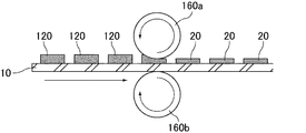
ロールプレスを用いた場合の加圧工程の一例について、図8を参照しながら説明する。
図8は、加圧工程の一例を模式的に示す断面図である。
図8に示すように、加圧工程では、基材10上に配置された電極組成物120をロールプレス160a及び160bにより加圧する。加圧工程によって、基材10上に電極組成物層20が形成される。
以上の工程により、連続するシート状の基材10の表面に電極組成物層20が配置された電極組成物層配置部が間欠的に配置された、図1に示すようなリチウムイオン電池用電極材が得られる。
An example of the pressurizing process when a roll press is used will be described with reference to FIG.
FIG. 8 is a cross-sectional view schematically showing an example of the pressurizing process.
As shown in FIG. 8, in the pressurizing step, the
Through the above steps, the electrode composition layer arrangement portion in which the
なお、ロールプレス160a及び160bは、後述する本発明のリチウムイオン電池用電極材の製造装置における加圧手段に相当する。 The roll presses 160a and 160b correspond to the pressurizing means in the apparatus for manufacturing the electrode material for a lithium ion battery of the present invention, which will be described later.
なお、図8に示す加圧工程は、除去工程の後に行われる加圧工程の例である。
除去工程の前に加圧工程を行う場合は、除去工程で使用される部材(例えばマスク層やカバー層)を、電極組成物とともに加圧してもよい。
The pressurizing step shown in FIG. 8 is an example of a pressurizing step performed after the removing step.
When the pressurizing step is performed before the removing step, the members (for example, mask layer and cover layer) used in the removing step may be pressurized together with the electrode composition.
上記手順により得られたリチウムイオン電池用電極材は、さらに電極組成物層非配置部において切断する工程を行い、所望の寸法のリチウムイオン電池用電極材としてもよい。 The electrode material for a lithium ion battery obtained by the above procedure may be further subjected to a step of cutting at a portion where the electrode composition layer is not arranged to obtain an electrode material for a lithium ion battery having a desired size.
本発明のリチウムイオン電池用電極材の製造方法により製造されたリチウムイオン電池用電極材では、リチウムイオン電池の電極に用いるために、複数の電極組成物層配置部を分離する場合、電極組成物層非配置部において切断することで、電極組成物層を切断することなく基材を切断して、複数の電極組成物層を得ることができるため、電極組成物層に割れや欠落が生じない。このとき、切断によって得られるリチウムイオン電池用電極材は、複数の電極組成物層配置部を有していてもよいし、単一の電極組成物層配置部を有していてもよい。
そのため、電極組成物の流動性が低い場合であっても、充分な耐久性能を有するリチウムイオン電池を製造するためのリチウムイオン電池用電極材を製造することができる。
In the electrode material for a lithium ion battery produced by the method for producing an electrode material for a lithium ion battery of the present invention, when a plurality of electrode composition layer arrangement portions are separated for use as an electrode of a lithium ion battery, the electrode composition By cutting in the layer non-arranged portion, the base material can be cut without cutting the electrode composition layer to obtain a plurality of electrode composition layers, so that the electrode composition layer is not cracked or chipped. .. At this time, the electrode material for a lithium ion battery obtained by cutting may have a plurality of electrode composition layer arrangement portions, or may have a single electrode composition layer arrangement portion.
Therefore, even when the fluidity of the electrode composition is low, it is possible to manufacture an electrode material for a lithium ion battery for manufacturing a lithium ion battery having sufficient durability.
なお、基材が集電体である場合、リチウムイオン電池用電極材そのものがリチウムイオン電池用電極となる。 When the base material is a current collector, the electrode material for the lithium ion battery itself becomes the electrode for the lithium ion battery.
電極組成物層非配置部において基材を切断する方法は特に限定されないが、公知の切断方法(回転式切断刃、ギロチン刃、トムソン型及びレーザーによる切断等)が挙げられる。 The method for cutting the base material in the non-arranged portion of the electrode composition layer is not particularly limited, and examples thereof include known cutting methods (rotary cutting blade, guillotine blade, Thomson type, laser cutting, etc.).
本発明のリチウムイオン電池用電極材の製造方法に用いられる電極組成物について説明する。 The electrode composition used in the method for producing an electrode material for a lithium ion battery of the present invention will be described.
電極組成物は、電極活物質と電解液とを含んでなることが好ましい。
電極活物質は、正極活物質であっても負極活物質であってもよい。
また、電極組成物は、必要に応じて、導電助剤を含んでいてもよい。
The electrode composition preferably contains an electrode active material and an electrolytic solution.
The electrode active material may be a positive electrode active material or a negative electrode active material.
In addition, the electrode composition may contain a conductive auxiliary agent, if necessary.
正極活物質としては、リチウムと遷移金属との複合酸化物{遷移金属が1種である複合酸化物(LiCoO2、LiNiO2、LiAlMnO4、LiMnO2及びLiMn2O4等)、遷移金属元素が2種である複合酸化物(例えばLiFeMnO4、LiNi1−xCoxO2、LiMn1−yCoyO2、LiNi1/3Co1/3Al1/3O2及びLiNi0.8Co0.15Al0.05O2)及び金属元素が3種類以上である複合酸化物[例えばLiMaM’bM’’cO2(M、M’及びM’’はそれぞれ異なる遷移金属元素であり、a+b+c=1を満たす。例えばLiNi1/3Mn1/3Co1/3O2)等]等}、リチウム含有遷移金属リン酸塩(例えばLiFePO4、LiCoPO4、LiMnPO4及びLiNiPO4)、遷移金属酸化物(例えばMnO2及びV2O5)、遷移金属硫化物(例えばMoS2及びTiS2)及び導電性高分子(例えばポリアニリン、ポリピロール、ポリチオフェン、ポリアセチレン及びポリ−p−フェニレン及びポリビニルカルバゾール)等が挙げられ、2種以上を併用してもよい。
なお、リチウム含有遷移金属リン酸塩は、遷移金属サイトの一部を他の遷移金属で置換したものであってもよい。
As the positive electrode active material, composite oxide of lithium and transition metal {composite oxide is a transition metal is one (LiCoO 2, LiNiO 2, LiAlMnO 4, LiMnO 2 and LiMn 2 O 4, etc.), transition metal elements Two types of composite oxides (eg LiFemnO 4 , LiNi 1-x Co x O 2 , LiMn 1-y Co y O 2 , LiNi 1/3 Co 1/3 Al 1/3 O 2 and LiNi 0.8 Co 0.15 Al 0.05 O 2) and a composite oxide metal element is three or more [e.g. LiM a M 'b M'' c O 2 (M, M' and M '' is different from the transition metal elements, respectively , Etc.}, lithium-containing transition metal phosphates (eg LiFePO 4 , LiCoPO 4 , LiMnPO 4 and LiNiPO 4 ), for example LiNi 1/3 Mn 1/3 Co 1/3 O 2) etc. ), Transition metal oxides (eg MnO 2 and V 2 O 5 ), transition metal sulfides (eg MoS 2 and TiS 2 ) and conductive polymers (eg polyaniline, polypyrrole, polythiophene, polyacetylene and poly-p-phenylene and (Polyvinylcarbazole) and the like, and two or more kinds may be used in combination.
The lithium-containing transition metal phosphate may be one in which a part of the transition metal site is replaced with another transition metal.
正極活物質の体積平均粒子径は、電池の電気特性の観点から、0.01〜100μmであることが好ましく、0.1〜35μmであることがより好ましく、2〜30μmであることがさらに好ましい。 The volume average particle size of the positive electrode active material is preferably 0.01 to 100 μm, more preferably 0.1 to 35 μm, and further preferably 2 to 30 μm from the viewpoint of the electrical characteristics of the battery. ..
負極活物質としては、炭素系材料[黒鉛、難黒鉛化性炭素、アモルファス炭素、樹脂焼成体(例えばフェノール樹脂及びフラン樹脂等を焼成し炭素化したもの等)、コークス類(例えばピッチコークス、ニードルコークス及び石油コークス等)及び炭素繊維等]、珪素系材料[珪素、酸化珪素(SiOx)、珪素−炭素複合体(炭素粒子の表面を珪素及び/又は炭化珪素で被覆したもの、珪素粒子又は酸化珪素粒子の表面を炭素及び/又は炭化珪素で被覆したもの並びに炭化珪素等)及び珪素合金(珪素−アルミニウム合金、珪素−リチウム合金、珪素−ニッケル合金、珪素−鉄合金、珪素−チタン合金、珪素−マンガン合金、珪素−銅合金及び珪素−スズ合金等)等]、導電性高分子(例えばポリアセチレン及びポリピロール等)、金属(スズ、アルミニウム、ジルコニウム及びチタン等)、金属酸化物(チタン酸化物及びリチウム・チタン酸化物等)及び金属合金(例えばリチウム−スズ合金、リチウム−アルミニウム合金及びリチウム−アルミニウム−マンガン合金等)等及びこれらと炭素系材料との混合物等が挙げられる。
上記負極活物質のうち、内部にリチウム又はリチウムイオンを含まないものについては、予め負極活物質の一部又は全部にリチウム又はリチウムイオンを含ませるプレドープ処理を施してもよい。
Examples of the negative electrode active material include carbon-based materials [graphite, non-graphitizable carbon, amorphous carbon, calcined resin (for example, phenol resin, furan resin, etc. are calcined and carbonized), cokes (for example, pitch coke, needle). Coke and petroleum coke, etc.) and carbon fibers], silicon-based materials [silicon, silicon oxide (SiOx), silicon-carbon composite (carbon particles whose surface is coated with silicon and / or silicon carbide, silicon particles or oxidation) Silicon particles whose surface is coated with carbon and / or silicon carbide, silicon carbide, etc.) and silicon alloys (silicon-aluminum alloy, silicon-lithium alloy, silicon-nickel alloy, silicon-iron alloy, silicon-titanium alloy, silicon -Manganese alloys, silicon-copper alloys, silicon-tin alloys, etc.)], conductive polymers (eg, polyacetylene and polypyrrole, etc.), metals (tin, aluminum, zirconium, titanium, etc.), metal oxides (titanium oxide and titanium oxide, etc.) (Lithium-titanium oxide, etc.) and metal alloys (for example, lithium-tin alloys, lithium-aluminum alloys, lithium-aluminum-manganese alloys, etc.) and mixtures of these with carbon-based materials can be mentioned.
Among the above-mentioned negative electrode active materials, those which do not contain lithium or lithium ions inside may be pre-doped with a part or all of the negative electrode active materials containing lithium or lithium ions in advance.
これらの中でも、電池容量等の観点から、炭素系材料、珪素系材料及びこれらの混合物が好ましく、炭素系材料としては、黒鉛、難黒鉛化性炭素及びアモルファス炭素がさらに好ましく、珪素系材料としては、酸化珪素及び珪素−炭素複合体がさらに好ましい。 Among these, carbon-based materials, silicon-based materials and mixtures thereof are preferable from the viewpoint of battery capacity and the like, graphite, non-graphitizable carbon and amorphous carbon are more preferable as carbon-based materials, and silicon-based materials are more preferable. , Silicon oxide and silicon-carbon composites are more preferred.
負極活物質の体積平均粒子径は、電池の電気特性の観点から、0.01〜100μmが好ましく、0.1〜20μmであることがより好ましく、2〜10μmであることがさらに好ましい。 The volume average particle size of the negative electrode active material is preferably 0.01 to 100 μm, more preferably 0.1 to 20 μm, and even more preferably 2 to 10 μm from the viewpoint of the electrical characteristics of the battery.
本明細書において、負極活物質の体積平均粒子径は、マイクロトラック法(レーザー回折・散乱法)によって求めた粒度分布における積算値50%での粒径(Dv50)を意味する。マイクロトラック法とは、レーザー光を粒子に照射することによって得られる散乱光を利用して粒度分布を求める方法である。なお、体積平均粒子径の測定には、レーザー回折・散乱式の粒子径分布測定装置[マイクロトラック・ベル(株)製のマイクロトラック等]を用いることができる。 In the present specification, the volume average particle size of the negative electrode active material means the particle size (Dv50) at an integrated value of 50% in the particle size distribution obtained by the microtrack method (laser diffraction / scattering method). The microtrack method is a method for obtaining a particle size distribution using scattered light obtained by irradiating particles with laser light. A laser diffraction / scattering type particle size distribution measuring device [Microtrack, etc. manufactured by Microtrack Bell Co., Ltd.] can be used for measuring the volume average particle size.
導電助剤は、導電性を有する材料から選択される。
具体的には、金属[ニッケル、アルミニウム、ステンレス(SUS)、銀、銅及びチタン等]、カーボン[グラファイト及びカーボンブラック(アセチレンブラック、ケッチェンブラック、ファーネスブラック、チャンネルブラック、サーマルランプブラック等)等]、及びこれらの混合物等が挙げられるが、これらに限定されるわけではない。
これらの導電助剤は1種単独で用いてもよいし、2種以上併用してもよい。また、これらの合金又は金属酸化物を用いてもよい。電気的安定性の観点から、好ましくはアルミニウム、ステンレス、カーボン、銀、銅、チタン及びこれらの混合物であり、より好ましくは銀、アルミニウム、ステンレス及びカーボンであり、さらに好ましくはカーボンである。またこれらの導電助剤としては、粒子系セラミック材料や樹脂材料の周りに導電性材料(上記した導電助剤の材料のうち金属のもの)をめっき等でコーティングしたものでもよい。
The conductive auxiliary agent is selected from materials having conductivity.
Specifically, metals [nickel, aluminum, stainless steel (SUS), silver, copper, titanium, etc.], carbon [graphite and carbon black (acetylene black, ketjen black, furnace black, channel black, thermal lamp black, etc.), etc.), etc. ], And a mixture thereof, etc., but is not limited to these.
These conductive aids may be used alone or in combination of two or more. Moreover, you may use these alloys or metal oxides. From the viewpoint of electrical stability, aluminum, stainless steel, carbon, silver, copper, titanium and mixtures thereof are preferable, silver, aluminum, stainless steel and carbon are more preferable, and carbon is even more preferable. Further, these conductive auxiliaries may be those obtained by coating a conductive material (a metal one among the above-mentioned conductive auxiliary materials) around a particle-based ceramic material or a resin material by plating or the like.
導電助剤の平均粒子径は、特に限定されるものではないが、電池の電気特性の観点から、0.01〜10μmであることが好ましく、0.02〜5μmであることがより好ましく、0.03〜1μmであることがさらに好ましい。なお、本明細書中において、「粒子径」とは、導電助剤の輪郭線上の任意の2点間の距離のうち、最大の距離Lを意味する。「平均粒子径」の値としては、走査型電子顕微鏡(SEM)や透過型電子顕微鏡(TEM)等の観察手段を用い、数〜数十視野中に観察される粒子の粒子径の平均値として算出される値を採用するものとする。 The average particle size of the conductive auxiliary agent is not particularly limited, but is preferably 0.01 to 10 μm, more preferably 0.02 to 5 μm, and 0, from the viewpoint of the electrical characteristics of the battery. It is more preferably .03 to 1 μm. In the present specification, the “particle size” means the maximum distance L among the distances between any two points on the contour line of the conductive auxiliary agent. The value of the "average particle size" is the average value of the particle size of the particles observed in several to several tens of fields using an observation means such as a scanning electron microscope (SEM) or a transmission electron microscope (TEM). The calculated value shall be adopted.
導電助剤の形状(形態)は、粒子形態に限られず、粒子形態以外の形態であってもよく、カーボンナノチューブ等、いわゆるフィラー系導電性樹脂組成物として実用化されている形態であってもよい。 The shape (form) of the conductive auxiliary agent is not limited to the particle form, and may be a form other than the particle form, and may be a form practically used as a so-called filler-based conductive resin composition such as carbon nanotubes. Good.
導電助剤は、その形状が繊維状である導電性繊維であってもよい。
導電性繊維としては、PAN系炭素繊維、ピッチ系炭素繊維等の炭素繊維、合成繊維の中に導電性のよい金属や黒鉛を均一に分散させてなる導電性繊維、ステンレス鋼のような金属を繊維化した金属繊維、有機物繊維の表面を金属で被覆した導電性繊維、有機物繊維の表面を導電性物質を含む樹脂で被覆した導電性繊維等が挙げられる。これらの導電性繊維の中では炭素繊維が好ましい。また、グラフェンを練りこんだポリプロピレン樹脂も好ましい。
導電助剤が導電性繊維である場合、その平均繊維径は0.1〜20μmであることが好ましい。
The conductive auxiliary agent may be a conductive fiber whose shape is fibrous.
As the conductive fibers, carbon fibers such as PAN-based carbon fibers and pitch-based carbon fibers, conductive fibers obtained by uniformly dispersing a metal having good conductivity or graphite in synthetic fibers, and metals such as stainless steel are used. Examples thereof include fibrous metal fibers, conductive fibers in which the surface of organic fibers is coated with metal, and conductive fibers in which the surface of organic fibers is coated with a resin containing a conductive substance. Among these conductive fibers, carbon fibers are preferable. Further, a polypropylene resin kneaded with graphene is also preferable.
When the conductive auxiliary agent is a conductive fiber, its average fiber diameter is preferably 0.1 to 20 μm.
電極活物質は、その表面の少なくとも一部が高分子化合物を含む被覆層により被覆された被覆活物質であってもよい。
電極活物質の周囲が被覆層で被覆されていると、電極の体積変化が緩和され、電極の膨張を抑制することができる。
なお、電極活物質として正極活物質を使用した場合の被覆活物質を被覆正極活物質といい、被覆組成物層を被覆正極組成物層ともいう。また電極活物質として負極活物質を使用した場合の被覆活物質を被覆負極活物質といい、被覆組成物層を被覆負極組成物層ともいう。
The electrode active material may be a coating active material in which at least a part of the surface thereof is coated with a coating layer containing a polymer compound.
When the periphery of the electrode active material is coated with a coating layer, the volume change of the electrode is alleviated and the expansion of the electrode can be suppressed.
When a positive electrode active material is used as the electrode active material, the coating active material is referred to as a coated positive electrode active material, and the coating composition layer is also referred to as a coated positive electrode composition layer. Further, the coating active material when the negative electrode active material is used as the electrode active material is referred to as a coated negative electrode active material, and the coating composition layer is also referred to as a coated negative electrode composition layer.
被覆層を構成する高分子化合物としては、特開2017−054703号公報に非水系二次電池活物質被覆用樹脂として記載されたものを好適に用いることができる。 As the polymer compound constituting the coating layer, those described as a resin for coating a non-aqueous secondary battery active material in Japanese Patent Application Laid-Open No. 2017-054703 can be preferably used.
電解液としては、リチウムイオン電池の製造に用いられる、電解質及び非水溶媒を含有する公知の電解液を使用することができる。 As the electrolytic solution, a known electrolytic solution containing an electrolyte and a non-aqueous solvent used in the production of a lithium ion battery can be used.
電解質としては、公知の電解液に用いられているもの等が使用でき、例えば、LiPF6、LiBF4、LiSbF6、LiAsF6及びLiClO4等の無機酸のリチウム塩、LiN(CF3SO2)2、LiN(C2F5SO2)2及びLiC(CF3SO2)3等の有機酸のリチウム塩等が挙げられる。これらの内、電池出力及び充放電サイクル特性の観点から好ましいのはLiPF6である。 As the electrolyte, those used in known electrolytes can be used, for example, lithium salts of inorganic acids such as LiPF 6 , LiBF 4 , LiSbF 6 , LiAsF 6 and LiClO 4 , LiN (CF 3 SO 2 ). 2. Lithium salts of organic acids such as LiN (C 2 F 5 SO 2 ) 2 and LiC (CF 3 SO 2 ) 3 can be mentioned. Of these, LiPF 6 is preferable from the viewpoint of battery output and charge / discharge cycle characteristics.
非水溶媒としては、公知の電解液に用いられているもの等が使用でき、例えば、ラクトン化合物、環状又は鎖状炭酸エステル、鎖状カルボン酸エステル、環状又は鎖状エーテル、リン酸エステル、ニトリル化合物、アミド化合物、スルホン、スルホラン等及びこれらの混合物を用いることができる。 As the non-aqueous solvent, those used in known electrolytic solutions can be used, for example, lactone compounds, cyclic or chain carbonates, chain carboxylic acid esters, cyclic or chain ethers, phosphate esters, nitriles. Compounds, amide compounds, sulfones, sulfolanes and the like and mixtures thereof can be used.
ラクトン化合物としては、5員環(γ−ブチロラクトン及びγ−バレロラクトン等)及び6員環のラクトン化合物(δ−バレロラクトン等)等を挙げることができる。 Examples of the lactone compound include a 5-membered ring (γ-butyrolactone, γ-valerolactone, etc.) and a 6-membered ring lactone compound (δ-valerolactone, etc.).
環状炭酸エステルとしては、プロピレンカーボネート、エチレンカーボネート及びブチレンカーボネート等が挙げられる。
鎖状炭酸エステルとしては、ジメチルカーボネート、メチルエチルカーボネート、ジエチルカーボネート、メチル−n−プロピルカーボネート、エチル−n−プロピルカーボネート及びジ−n−プロピルカーボネート等が挙げられる。
Examples of the cyclic carbonate include propylene carbonate, ethylene carbonate and butylene carbonate.
Examples of the chain carbonate ester include dimethyl carbonate, methyl ethyl carbonate, diethyl carbonate, methyl-n-propyl carbonate, ethyl-n-propyl carbonate, di-n-propyl carbonate and the like.
鎖状カルボン酸エステルとしては、酢酸メチル、酢酸エチル、酢酸プロピル及びプロピオン酸メチル等が挙げられる。
環状エーテルとしては、テトラヒドロフラン、テトラヒドロピラン、1,3−ジオキソラン及び1,4−ジオキサン等が挙げられる。
鎖状エーテルとしては、ジメトキシメタン及び1,2−ジメトキシエタン等が挙げられる。
Examples of the chain carboxylic acid ester include methyl acetate, ethyl acetate, propyl acetate, methyl propionate and the like.
Examples of the cyclic ether include tetrahydrofuran, tetrahydropyran, 1,3-dioxolane, 1,4-dioxane and the like.
Examples of the chain ether include dimethoxymethane and 1,2-dimethoxyethane.
リン酸エステルとしては、リン酸トリメチル、リン酸トリエチル、リン酸エチルジメチル、リン酸ジエチルメチル、リン酸トリプロピル、リン酸トリブチル、リン酸トリ(トリフルオロメチル)、リン酸トリ(トリクロロメチル)、リン酸トリ(トリフルオロエチル)、リン酸トリ(トリパーフルオロエチル)、2−エトキシ−1,3,2−ジオキサホスホラン−2−オン、2−トリフルオロエトキシ−1,3,2−ジオキサホスホラン−2−オン及び2−メトキシエトキシ−1,3,2−ジオキサホスホラン−2−オン等が挙げられる。
ニトリル化合物としては、アセトニトリル等が挙げられる。
アミド化合物としては、DMF等が挙げられる。
スルホンとしては、ジメチルスルホン及びジエチルスルホン等が挙げられる。
非水溶媒は1種を単独で用いてもよいし、2種以上を併用してもよい。
Examples of the phosphate ester include trimethyl phosphate, triethyl phosphate, ethyl dimethyl phosphate, diethyl methyl phosphate, tripropyl phosphate, tributyl phosphate, tri (trifluoromethyl) phosphate, tri (trichloromethyl) phosphate, and so on. Tri (trifluoroethyl) phosphate, tri (triperfluoroethyl) phosphate, 2-ethoxy-1,3,2-dioxaphosphoran-2-one, 2-trifluoroethoxy-1,3,2- Examples thereof include dioxaphosphoran-2-one and 2-methoxyethoxy-1,3,2-dioxaphosphoran-2-one.
Examples of the nitrile compound include acetonitrile and the like.
Examples of the amide compound include DMF and the like.
Examples of the sulfone include dimethyl sulfone and diethyl sulfone.
One type of non-aqueous solvent may be used alone, or two or more types may be used in combination.
非水溶媒の内、電池出力及び充放電サイクル特性の観点から好ましいのは、ラクトン化合物、環状炭酸エステル、鎖状炭酸エステル及びリン酸エステルであり、更に好ましいのはラクトン化合物、環状炭酸エステル及び鎖状炭酸エステルであり、特に好ましいのは環状炭酸エステルと鎖状炭酸エステルの混合液である。最も好ましいのはエチレンカーボネートとジメチルカーボネートの混合液、又は、エチレンカーボネートとジエチルカーボネートの混合液である。 Among the non-aqueous solvents, lactone compounds, cyclic carbonates, chain carbonates and phosphate esters are preferable from the viewpoint of battery output and charge / discharge cycle characteristics, and lactone compounds, cyclic carbonates and chains are more preferable. A carbonic acid ester is particularly preferable, and a mixed solution of a cyclic carbonic acid ester and a chain carbonic acid ester is particularly preferable. The most preferable is a mixed solution of ethylene carbonate and dimethyl carbonate, or a mixed solution of ethylene carbonate and diethyl carbonate.
上述した被覆活物質を製造する方法について説明する。
被覆活物質は、例えば、高分子化合物及び電極活物質並びに必要により用いる導電剤を混合することによって製造してもよく、被覆層に導電剤を用いる場合には高分子化合物と導電剤とを混合して被覆材を準備したのち、該被覆材と電極活物質とを混合することにより製造してもよく、高分子化合物、導電剤及び電極活物質を混合することによって製造してもよい。
なお、電極活物質と高分子化合物と導電剤とを混合する場合、混合順序には特に制限はないが、電極活物質と高分子化合物とを混合した後、更に導電剤を加えて更に混合することが好ましい。
上記方法により、高分子化合物と必要により用いる導電剤を含む被覆層によって電極活物質の表面の少なくとも一部が被覆される。
The method for producing the above-mentioned coating active material will be described.
The coating active material may be produced, for example, by mixing a polymer compound, an electrode active material, and a conductive agent used if necessary, and when a conductive agent is used for the coating layer, the polymer compound and the conductive agent are mixed. After preparing the coating material, the coating material may be produced by mixing the coating material with the electrode active material, or may be produced by mixing the polymer compound, the conductive agent and the electrode active material.
When the electrode active material, the polymer compound, and the conductive agent are mixed, the mixing order is not particularly limited, but after the electrode active material and the polymer compound are mixed, the conductive agent is further added and further mixed. Is preferable.
By the above method, at least a part of the surface of the electrode active material is coated with a coating layer containing a polymer compound and a conductive agent used if necessary.
被覆材の任意成分である導電剤としては、電極組成物を構成する導電助剤と同様のものを好適に用いることができる。 As the conductive agent which is an optional component of the coating material, the same conductive agent as the conductive auxiliary agent constituting the electrode composition can be preferably used.
電極組成物には、さらに、溶液乾燥型の公知の電極用バインダー(カルボキシメチルセルロース、SBRラテックス及びポリフッ化ビニリデン等)や粘着性樹脂等が含まれていてもよい。
ただし、公知の電極用バインダーではなく、粘着性樹脂を含むことが望ましい。電極組成物が上記の溶液乾燥型の公知の電極用バインダーを含む場合には、電極組成物層を形成した後に乾燥工程を行うことで一体化する必要があるが、粘着性樹脂を含む場合には、乾燥工程を行うことなく常温において僅かな圧力で電極組成物を一体化することができる。乾燥工程を行わない場合、加熱による電極組成物の収縮や亀裂の発生がおこらないため好ましい。
また、電極活物質、電解液及び粘着性樹脂を含む電極組成物は、電極組成物層を形成した後であっても、電極組成物層が非結着体のままで維持される。電極組成物層が非結着体であれば、電極組成物層を厚くすることができ、高容量の電池を得ることができ好ましい。
粘着性樹脂としては、被覆層を構成する高分子化合物(特開2017−054703号公報に記載された非水系二次電池活物質被覆用樹脂等)に少量の有機溶剤を混合してそのガラス転移温度を室温以下に調整したもの、及び、特開平10−255805公報等に粘着剤として記載されたものを好適に用いることができる。
ここで、非結着体とは、電極組成物を構成する電極活物質同士が、互いに結合していないことを意味し、結合とは不可逆的に電極活物質同士が固定されていることを意味する。
なお、溶液乾燥型の電極用バインダーは、溶媒成分を揮発させることで乾燥、固体化して活物質同士を強固に固定するものを意味する。一方、粘着性樹脂は、粘着性(水、溶媒、熱等を使用せずに僅かな圧力を加えることで接着する性質)を有する樹脂を意味する。
溶液乾燥型の電極用バインダーと粘着性樹脂とは異なる材料である。
The electrode composition may further contain a solution-drying type known electrode binder (carboxymethyl cellulose, SBR latex, polyvinylidene fluoride, etc.), an adhesive resin, and the like.
However, it is desirable to contain an adhesive resin instead of a known electrode binder. When the electrode composition contains the above-mentioned solution-drying type known electrode binder, it is necessary to carry out a drying step after forming the electrode composition layer, but when it contains an adhesive resin, it is necessary to integrate the electrode composition. Can integrate the electrode composition with a slight pressure at room temperature without performing a drying step. When the drying step is not performed, the electrode composition does not shrink or crack due to heating, which is preferable.
Further, in the electrode composition containing the electrode active material, the electrolytic solution and the adhesive resin, the electrode composition layer is maintained as a non-bound body even after the electrode composition layer is formed. When the electrode composition layer is a non-bonded body, the electrode composition layer can be made thicker, and a high-capacity battery can be obtained, which is preferable.
As the adhesive resin, a small amount of an organic solvent is mixed with a polymer compound (such as the resin for coating a non-aqueous secondary battery active material described in JP-A-2017-054703) constituting the coating layer, and the glass transition thereof is performed. Those whose temperature is adjusted to room temperature or lower and those described as an adhesive in JP-A No. 10-255805 can be preferably used.
Here, the non-bonded body means that the electrode active materials constituting the electrode composition are not bonded to each other, and means that the electrode active materials are fixed to each other irreversibly to the bond. To do.
The solution-drying type binder for electrodes means a binder that dries and solidifies by volatilizing a solvent component to firmly fix the active materials to each other. On the other hand, the adhesive resin means a resin having adhesiveness (property of adhering by applying a slight pressure without using water, a solvent, heat, etc.).
The solution-drying type binder for electrodes and the adhesive resin are different materials.
本発明のリチウムイオン電池用電極材の製造方法において、電極組成物は、電極活物質と電解液を含んでなる湿潤粉体であることが好ましい。
湿潤粉体は、ペンデュラー状態又はファニキュラー状態であることがより望ましい。
In the method for producing an electrode material for a lithium ion battery of the present invention, the electrode composition is preferably a wet powder containing an electrode active material and an electrolytic solution.
It is more desirable that the wet powder is in a pendular state or a funicular state.
湿潤粉体における電解液の割合は、特に限定されないが、正極の場合には電解液の割合を湿潤粉体全体の0.5〜15重量%とすることが好ましく、0.5〜5重量%とすることがより好ましく、0.5〜3重量%とすることがさらに好ましい。また、負極の場合には、電解液の割合を湿潤粉体全体の0.5〜25重量%とすることが好ましく、0.5〜10重量%とすることがより好ましく、0.5〜5重量%とすることがさらに好ましい。 The ratio of the electrolytic solution in the wet powder is not particularly limited, but in the case of the positive electrode, the ratio of the electrolytic solution is preferably 0.5 to 15% by weight, and 0.5 to 5% by weight of the entire wet powder. More preferably, it is more preferably 0.5 to 3% by weight. In the case of the negative electrode, the proportion of the electrolytic solution is preferably 0.5 to 25% by weight, more preferably 0.5 to 10% by weight, and 0.5 to 5% by weight of the entire wet powder. It is more preferable to use% by weight.
本発明のリチウムイオン電池用電極材からリチウムイオン電池を製造する方法としては、例えば、電極活物質として正極活物質を用いて製造されたリチウムイオン電池用正極材と、電極活物質として負極活物質を用いて製造されたリチウムイオン電池用負極材とを、セパレータを介して、電極組成物層同士(正極組成物層と負極組成物層)が対向するように積層して蓄電素子を作製し、この蓄電素子を電池外装体に収容して封止する方法が挙げられる。
封止前には、必要に応じて電解液を添加してもよい。
また、リチウムイオン電池用正極材とリチウムイオン電池用負極材とをセパレータを介して電極組成物層同士が対向するように積層し、正極集電体と負極集電体との外周を耐電解液性を有する樹脂等で封止することで、外装体を使用せずにリチウムイオン電池を製造することもできる。
As a method for producing a lithium ion battery from the electrode material for a lithium ion battery of the present invention, for example, a positive electrode material for a lithium ion battery manufactured using a positive electrode active material as an electrode active material and a negative electrode active material as an electrode active material. The negative electrode material for a lithium ion battery manufactured using the above is laminated with the electrode composition layers (positive electrode composition layer and negative electrode composition layer) facing each other via a separator to produce a power storage element. Examples thereof include a method in which the power storage element is housed in the battery outer body and sealed.
If necessary, an electrolytic solution may be added before sealing.
Further, the positive electrode material for a lithium ion battery and the negative electrode material for a lithium ion battery are laminated so that the electrode composition layers face each other via a separator, and the outer periphery of the positive electrode current collector and the negative electrode current collector is an electrolytic resistant liquid. It is also possible to manufacture a lithium ion battery without using an exterior body by sealing it with a resin or the like having a property.
[リチウムイオン電池用電極材の製造装置]
本発明のリチウムイオン電池用電極材の製造装置は、連続するシート状の基材の表面に電極活物質を含む電極組成物からなる電極組成物層が配置された電極組成物層配置部が、間欠的に配置されたリチウムイオン電池用電極材の製造装置であって、上記基材上に上記電極組成物を連続的に供給する供給手段と、上記供給手段によって上記基材上に供給された上記電極組成物を加圧して上記電極組成物層を得る加圧手段と、上記供給手段によって上記基材上に供給された上記電極組成物の一部を除去して、上記基材上に電極組成物層配置部を形成する除去手段と、を備えることを特徴とする。
[Manufacturing equipment for electrode materials for lithium-ion batteries]
In the device for producing an electrode material for a lithium ion battery of the present invention, an electrode composition layer arrangement portion in which an electrode composition layer composed of an electrode composition containing an electrode active material is arranged on the surface of a continuous sheet-like base material is provided. An intermittently arranged electrode material manufacturing apparatus for a lithium ion battery, the electrode composition is continuously supplied onto the base material, and the electrode composition is supplied onto the base material by the supply means. A pressurizing means for pressurizing the electrode composition to obtain the electrode composition layer and a part of the electrode composition supplied on the base material by the supply means are removed to obtain an electrode on the base material. It is characterized by comprising a removing means for forming a composition layer arrangement portion.
供給手段としては、例えば、公知の粉体定量供給装置(ホッパー等)等が挙げられる。 Examples of the supply means include a known powder quantitative supply device (hopper or the like).
除去手段としては、例えば、基材上に配置された電極組成物の上にカバー層を載置するカバー層載置手段と、カバー層が設けられていない領域の電極組成物を除去する電極組成物除去手段とを備える手段や、電極組成物が供給される前の基材の表面に、開口部を有するマスク層を載置するマスク層載置手段と、基材及びマスク層の表面に電極組成物が供給された後に、マスク層を剥がす剥離手段とを備える手段が挙げられる。
これらの中では、マスク層載置手段と剥離手段とを備えることが好ましい。
As the removing means, for example, a cover layer mounting means for mounting the cover layer on the electrode composition arranged on the base material and an electrode composition for removing the electrode composition in the region where the cover layer is not provided. A means for providing a substance removing means, a mask layer mounting means for mounting a mask layer having an opening on the surface of the base material before the electrode composition is supplied, and an electrode on the surface of the base material and the mask layer. A means including a peeling means for peeling the mask layer after the composition is supplied can be mentioned.
Among these, it is preferable to provide a mask layer placing means and a peeling means.
好ましい加圧手段としては、平板プレス及びロールプレス等が挙げられる。 Preferred pressurizing means include a flat plate press, a roll press and the like.
本発明のリチウムイオン電池用電極材の製造装置の一例について、図9を参照しながら説明する。
図9は、本発明のリチウムイオン電池用電極材の製造装置を用いてリチウムイオン電池用電極材を製造する様子の一例を模式的に示す断面図である。
図9に示すリチウムイオン電池用電極材の製造装置200は、供給手段であるホッパー110と、除去手段であるマスク層140、マスク層載置用ローラ170及びマスク層剥離用ローラ180と、加圧手段であるロールプレス160a及び160bとを備える。
基材10は、基材移動用ローラ190により一方向(矢印方向)に移動している。まず、開口部Aを有するマスク層140が、マスク層載置用ローラ170によって基材10上に載置される。その後、基材10上及びマスク層140の開口部Aの全面にホッパー110から電極組成物120が供給される。供給された電極組成物120はスキージ130によりその厚さが調整される。その後、マスク層剥離用ローラ180によって、マスク層140は、基材10の表面から剥離される。最後に、基材10上に残存する電極組成物120を加圧手段であるロールプレス160a及び160bによって加圧して、基材10上に電極組成物層20を形成することで、本発明のリチウムイオン電池用電極材を製造することができる。
An example of the apparatus for manufacturing the electrode material for a lithium ion battery of the present invention will be described with reference to FIG.
FIG. 9 is a cross-sectional view schematically showing an example of manufacturing an electrode material for a lithium ion battery using the device for manufacturing an electrode material for a lithium ion battery of the present invention.
The
The
本発明のリチウムイオン電池用電極材の製造装置においては、除去手段が加圧手段を兼ねていてもよい。 In the apparatus for producing an electrode material for a lithium ion battery of the present invention, the removing means may also serve as a pressurizing means.
除去手段が加圧手段を兼ねている場合の一例について、図10を参照しながら説明する。
図10は、本発明のリチウムイオン電池用電極材の製造装置を用いてリチウムイオン電池用電極材を製造する様子の別の一例を模式的に示す断面図である。
図10に示すリチウムイオン電池用電極材の製造装置300は、供給手段であるホッパー110と、除去手段であるマスク層140と、加圧手段であるロールプレス160bと、加圧兼マスク層剥離用ローラ195とを備える。加圧兼マスク層剥離用ローラ195は、除去手段であるマスク層剥離用ローラと加圧手段であるロールプレスを兼ねている。
基材10は、基材移動用ローラ190により一方向(矢印方向)に移動している。まず、開口部Aを有するマスク層140が、マスク層載置用ローラ170によって基材10上に載置される。その後、基材10上及びマスク層140の開口部Aの全面にホッパー110から電極組成物120が供給される。供給された電極組成物120はスキージ130によりその厚さが調整される。その後、電極組成物120が加圧兼マスク層剥離用ローラ195及びロールプレス160bによって加圧されるとともに、マスク層140が基材10の表面から剥離される。以上の工程により、基材10上に電極組成物層20を形成して、本発明のリチウムイオン電池用電極材を製造することができる。
An example in which the removing means also serves as the pressurizing means will be described with reference to FIG.
FIG. 10 is a cross-sectional view schematically showing another example of manufacturing an electrode material for a lithium ion battery using the device for manufacturing an electrode material for a lithium ion battery of the present invention.
The
The
次に本発明を実施例によって具体的に説明するが、本発明の主旨を逸脱しない限り本発明は実施例に限定されるものではない。なお、特記しない限り部は重量部、%は重量%を意味する。 Next, the present invention will be specifically described with reference to Examples, but the present invention is not limited to the Examples as long as the gist of the present invention is not deviated. Unless otherwise specified, parts mean parts by weight and% means% by weight.
<製造例1:粘着性樹脂の製造>
攪拌機、温度計、還流冷却管、滴下ロート及び窒素ガス導入管を付した4つ口コルベンに、酢酸ビニル5.0部、2−エチルヘキシルアクリレート23.7部及び酢酸エチル185.5部を仕込み75℃に昇温した。酢酸ビニル11.1部、2−エチルヘキシルアクリレート21.0部、2−ヒドロキシエチルメタクリレート28.1部、アクリル酸11.1部及び2,2’−アゾビス(2,4−ジメチルバレロニトリル)0.200部及び2,2’−アゾビス(2−メチルブチロニトリル)0.200部を混合した。得られた単量体混合液をコルベン内に窒素を吹き込みながら、滴下ロートで4時間かけて連続的に滴下してラジカル重合を行った。滴下終了後、2,2’−アゾビス(2,4−ジメチルバレロニトリル)0.800部を酢酸エチル12.4部に溶解した溶液を滴下ロートを用いて、重合を開始してから6〜8時間目にかけて連続的に追加した。さらに、沸点で重合を2時間継続し、酢酸エチルを702.4部加えて樹脂濃度10重量%の粘着性樹脂の溶液を得た。その後、100℃の減圧乾燥機内に3時間入れることで酢酸エチルを除去した。粘着性樹脂の重量平均分子量(以下、Mwと略記する)は420,000であった。
Mwは、以下の条件でゲルパーミエーションクロマトグラフィー測定により求めた。
装置:「HLC−8120GPC」[東ソー(株)製]
カラム:「TSKgel GMHXL」(2本)、「TSKgel Multipore HXL−Mを各1本連結したもの」[いずれも東ソー(株)製]
試料溶液:0.25重量%のテトラヒドロフラン溶液
溶液注入量:10μL
流量:0.6mL/分
測定温度:40℃
検出装置:屈折率検出器
基準物質:標準ポリスチレン[東ソー(株)製]
<Manufacturing example 1: Manufacture of adhesive resin>
5.0 parts of vinyl acetate, 23.7 parts of 2-ethylhexyl acrylate and 185.5 parts of ethyl acetate were charged into a 4-port corben equipped with a stirrer, a thermometer, a reflux condenser, a dropping funnel and a nitrogen gas introduction pipe. The temperature was raised to ° C. 11.1 parts of vinyl acetate, 21.0 parts of 2-ethylhexyl acrylate, 28.1 parts of 2-hydroxyethyl methacrylate, 11.1 parts of acrylic acid and 2,2'-azobis (2,4-dimethylvaleronitrile) 0. 200 parts and 0.200 parts of 2,2'-azobis (2-methylbutyronitrile) were mixed. The obtained monomer mixed solution was continuously added dropwise over 4 hours with a dropping funnel while blowing nitrogen into Kolben to carry out radical polymerization. After completion of the dropping, a solution prepared by dissolving 0.800 parts of 2,2'-azobis (2,4-dimethylvaleronitrile) in 12.4 parts of ethyl acetate was started using a dropping funnel, and then 6 to 8 Added continuously over time. Further, the polymerization was continued at the boiling point for 2 hours, and 702.4 parts of ethyl acetate was added to obtain a solution of an adhesive resin having a resin concentration of 10% by weight. Then, the ethyl acetate was removed by putting it in a vacuum dryer at 100 ° C. for 3 hours. The weight average molecular weight of the adhesive resin (hereinafter abbreviated as Mw) was 420,000.
Mw was determined by gel permeation chromatography measurement under the following conditions.
Equipment: "HLC-8120GPC" [manufactured by Tosoh Corporation]
Column: "TSKgel GMHXL" (2 pieces), "TSKgel Multipore HXL-M 1 piece each connected" [both manufactured by Tosoh Corporation]
Sample solution: 0.25 wt% tetrahydrofuran solution Injection volume: 10 μL
Flow rate: 0.6 mL / min Measurement temperature: 40 ° C
Detector: Refractive index detector Reference material: Standard polystyrene [manufactured by Tosoh Corporation]
<製造例2:電解液の調製>
エチレンカーボネート(EC)とプロピレンカーボネート(PC)の混合溶媒(体積比率でEC:PC=1:1)にLiN(FSO2)2(LiFSI)を2mol/Lの割合で溶解させ、電解液を調製した。
<Production Example 2: Preparation of electrolyte>
Prepare an electrolytic solution by dissolving LiN (FSO 2 ) 2 (LiFSI) in a mixed solvent of ethylene carbonate (EC) and propylene carbonate (PC) at a ratio of 2 mol / L in a mixed solvent (EC: PC = 1: 1 in volume ratio). did.
<製造例3:正極組成物の作製>
万能混合機ハイスピードミキサーFS25[(株)アーステクニカ製]を用いて、炭素繊維[大阪ガスケミカル(株)製 ドナカーボ・ミルド S−243]20部と製造例1で得た粘着性樹脂の溶液300部とアセチレンブラック[デンカ(株)製 デンカブラック]57部とLiNi0.8Co0.15Al0.05O2[(株)BASF戸田バッテリーマテリアルズ製HED NCA−7050、体積平均粒子径10μm]875部を室温、720rpmの条件で15分撹拌した。撹拌を維持したまま0.01MPaまで減圧し、次いで撹拌と減圧度を維持したまま温度を80℃まで昇温し、撹拌、減圧度及び温度を8時間維持して揮発分を留去した。得られた混合物を300μmの金属メッシュを取り付けたハンマークラッシャーNH−34S[(株)三庄インダストリー製]で粉砕し造粒を行い、正極活物質と粘着性樹脂との混合造粒物を得た。
<Production Example 3: Preparation of positive electrode composition>
Using the universal mixer high-speed mixer FS25 [manufactured by EarthTechnica Co., Ltd.], 20 parts of carbon fiber [Donacabo Mild S-243 manufactured by Osaka Gas Chemical Co., Ltd.] and the adhesive resin solution obtained in Production Example 1 300 parts and acetylene black [Denka Black manufactured by Denka Co., Ltd.] 57 parts and LiNi 0.8 Co 0.15 Al 0.05 O 2 [BASF Toda Battery Materials Co., Ltd. HED NCA-7050, volume
<製造例4:正極組成物の湿潤粉体の作製>
製造例3で得られた混合造粒物99.0部と製造例2で作製した電解液1.0部とを遊星撹拌型混合混練装置{あわとり練太郎[(株)シンキー製]}に入れ、2000rpmで5分間混合して、正極組成物の合計重量に基づく上記電解液の重量割合が1.0重量%である正極組成物の湿潤粉体を作製した。
<Production Example 4: Preparation of Wet Powder of Positive Electrode Composition>
99.0 parts of the mixed granules obtained in Production Example 3 and 1.0 part of the electrolytic solution prepared in Production Example 2 were put into a planetary stirring type mixing and kneading device {Awatori Kentarou [manufactured by Shinky Co., Ltd.]}. The mixture was added and mixed at 2000 rpm for 5 minutes to prepare a wet powder of the positive electrode composition in which the weight ratio of the electrolytic solution based on the total weight of the positive electrode composition was 1.0% by weight.
<実施例1>
(1)供給工程
アプリケータ用自動塗工機[イーガーコーポレーション製卓上テストコーター(型式:EGPI−1210)]にセットした厚さ100μmの離型紙上に、幅42mm、長さ57mmの開口部を、長さ方向に29mmの間隔を隔てて2つ有する、厚み600μm、幅90mm、長さ227mmのSUS製シート状のマスクを配置した。さらに製造例4で作製した正極組成物の湿潤粉体10gを山状に乗せた。さらにマイクロメーター付フィルムアプリケーター[イーガーコーポレーション製]をギャップ間隔0でマスク上に乗せた。マイクロメーター付フィルムアプリケータを正極組成物の湿潤粉体の山の上を移動速度20mm/sの一定速度で平行移動させ、山の表面を擦切る操作を行った。なお、擦切りを行った後、電極組成物の表面に線状のキズが観察された場合にはキズの発生がない表面が得られるまで擦切りの操作をやり直した。
(2)除去工程
擦切りを行った後、離型紙上に配置したSUS製シート状のマスクを取り外し、離型紙上に電極組成物が間欠的に配置された正極組成物層を得た。正極組成物層の上面視寸法は、幅42mm、長さ57mmであり、長さ方向に29mmの間隔を隔てて2つの正極組成物層が配置されている。
(3)加圧工程
続いて、正極組成物層が配置された基材をロールプレス機にセットし、以下の条件で加圧を行い、リチウムイオン電池用電極材(1A)を得た。
ロールプレス機から排出されたリチウムイオン電池用電極材(1A)は、ガラス板の上に載せて移動しても形状が壊れない程度にしっかり固められており、平滑な表面を有していた。
<ロールプレス機の条件>
・ロールサイズ:250mmφ×400mm
・ロール回転速度:0.2m/分
・ロールの間隔(ギャップ):100μm
・線圧:1ton/cm
<Example 1>
(1) Supply process An opening with a width of 42 mm and a length of 57 mm is formed on a 100 μm-thick release paper set in an automatic coating machine for an applicator [Eager Corporation desktop test coater (model: EGPI-1210)]. A SUS sheet-shaped mask having a thickness of 600 μm, a width of 90 mm, and a length of 227 mm having two masks having an interval of 29 mm in the length direction was arranged. Further, 10 g of the wet powder of the positive electrode composition prepared in Production Example 4 was placed in a mountain shape. Further, a film applicator with a micrometer [manufactured by Eager Corporation] was placed on the mask with a gap interval of 0. A film applicator with a micrometer was translated on a pile of wet powder of the positive electrode composition at a constant moving speed of 20 mm / s, and the surface of the pile was scraped off. After the scraping was performed, when linear scratches were observed on the surface of the electrode composition, the scraping operation was repeated until a surface without scratches was obtained.
(2) Removal Step After scraping was performed, the SUS sheet-shaped mask placed on the paper pattern was removed to obtain a positive electrode composition layer in which the electrode composition was intermittently placed on the paper pattern. The top view dimensions of the positive electrode composition layer are 42 mm in width and 57 mm in length, and two positive electrode composition layers are arranged with an interval of 29 mm in the length direction.
(3) Pressurization Step Subsequently, the base material on which the positive electrode composition layer was arranged was set in a roll press machine, and pressurization was performed under the following conditions to obtain an electrode material (1A) for a lithium ion battery.
The electrode material (1A) for a lithium ion battery discharged from the roll press machine was firmly solidified to the extent that its shape was not broken even when it was placed on a glass plate and moved, and had a smooth surface.
<Conditions for roll press machine>
・ Roll size: 250 mmφ x 400 mm
・ Roll rotation speed: 0.2 m / min ・ Roll interval (gap): 100 μm
・ Linear pressure: 1 ton / cm
<実施例2>
(1)供給工程
アプリケータ用自動塗工機[イーガーコーポレーション製卓上テストコーター(型式:EGPI−1210)]にセットした厚さ100μmの離型紙上に、製造例4で作製した正極活物質組成物の湿潤粉体10gを山状に乗せた。さらにマイクロメーター付フィルムアプリケーター[イーガーコーポレーション製]をギャップ間隔600μmにして離型紙上に乗せた。マイクロメーター付フィルムアプリケータを正極組成物の湿潤粉体の山の上を移動速度20mm/sの一定速度で平行移動させ、山の表面を擦切る操作を行った。なお、擦切りを行った後、表面に線状のキズが観察された場合にはキズの発生がない表面が得られるまで擦切りの操作をやり直した。
剥離紙上に供給された電極組成物の上面視寸法は、幅42mm、長さ150mmであった。
(2)除去工程
擦切りを行った後、幅42mm、長さ57mmの長方形のSUS製の板状部材(カバー層)を2つ、長さ方向に29mmの間隔を隔てて、擦切った電極組成物上に載せた。板状部材の外側にはみ出した電極組成物を吸引機[コトヒラ工業製クリーンルーム用集じん機(型式:KDC−C01)]で吸引除去した。吸引除去した後に、板状部材を取り外し、離型紙上に電極組成物を間欠的に配置した。
(3)加圧工程
実施例1と同様の条件で加圧を行い、リチウムイオン電池用電極材(1B)を得た。
<Example 2>
(1) Supply process The positive electrode active material composition prepared in Production Example 4 on a 100 μm-thick release paper set in an automatic coating machine for an applicator [Eager Corporation desktop test coater (model: EGPI-1210)]. 10 g of the wet powder of No. 1 was placed in a mountain shape. Further, a film applicator with a micrometer [manufactured by Eager Corporation] was placed on a paper pattern with a gap interval of 600 μm. A film applicator with a micrometer was translated on a pile of wet powder of the positive electrode composition at a constant moving speed of 20 mm / s, and the surface of the pile was scraped off. After the scraping was performed, when linear scratches were observed on the surface, the scraping operation was repeated until a surface without scratches was obtained.
The top view dimensions of the electrode composition supplied on the release paper were 42 mm in width and 150 mm in length.
(2) Removal step After scraping, two rectangular SUS plate-shaped members (cover layers) having a width of 42 mm and a length of 57 mm are separated by a distance of 29 mm in the length direction, and the electrode composition is scraped. I put it on the thing. The electrode composition protruding to the outside of the plate-shaped member was suction-removed with a suction machine [Kotohira Kogyo's clean room dust collector (model: KDC-C01)]. After removal by suction, the plate-shaped member was removed, and the electrode composition was intermittently placed on the paper pattern.
(3) Pressurization Step Pressurization was performed under the same conditions as in Example 1 to obtain an electrode material (1B) for a lithium ion battery.
<実施例3>
(1)供給工程
アプリケータ用自動塗工機[イーガーコーポレーション製卓上テストコーター(型式:EGPI−1210)]にセットした厚さ100μmの離型紙上に、幅44mm、長さ59mmの開口部を、長さ方向に19mmの間隔を隔てて2つ有する、厚み600μm、幅90mm、長さ227mmのSUS製シート状のマスクを配置した。さらに製造例4で作製した正極組成物の湿潤粉体10gを山状に乗せた。さらにマイクロメーター付フィルムアプリケーター[イーガーコーポレーション製]をギャップ間隔0でマスク上に乗せた。マイクロメーター付フィルムアプリケータを正極組成物の湿潤粉体の山の上を移動速度20mm/sの一定速度で平行移動させ、山の表面を擦切る操作を行った。なお、擦切りを行った後、電極組成物の表面に線状のキズが観察された場合にはキズの発生がない表面が得られるまで擦切りの操作をやり直した。
離型紙上には、幅50mm、長さ67mmの電極組成物層が、長さ方向に19mmの間隔を隔てて間欠的に配置されている。
(2)除去工程
剥離紙上に配置された電極組成物の上に、幅42mm、長さ57mmの長方形のSUS製の板状部材(カバー層)を2つ、長さ方向に29mmの間隔を隔てて、擦切った電極組成物上に載せた。このとき、上面視において板状部材がマスクに重ならないように、板状部材が配置される位置を調整した。板状部材の上面視寸法はマスクの開口部の上面視寸法よりも小さいため、板状部材の外側かつマスクの開口部の内側には電極組成物がわずかに露出している。
板状部材の外側とマスクの開口部に囲まれる領域に露出した電極組成物及びマスク上面部に存在する電極組成物を吸引機[コトヒラ工業製クリーンルーム用集じん機(型式:KDC−C01)]で吸引除去した。吸引除去した後に、板状部材を取り外し、離型紙上に電極組成物を間欠的に配置した。
(3)加圧工程
実施例1と同様の条件で加圧を行い、リチウムイオン電池用電極材(1C)を得た。
<Example 3>
(1) Supply process An opening with a width of 44 mm and a length of 59 mm is formed on a 100 μm-thick release paper set in an automatic coating machine for an applicator [Eager Corporation desktop test coater (model: EGPI-1210)]. A SUS sheet-shaped mask having a thickness of 600 μm, a width of 90 mm, and a length of 227 mm having two masks having an interval of 19 mm in the length direction was arranged. Further, 10 g of the wet powder of the positive electrode composition prepared in Production Example 4 was placed in a mountain shape. Further, a film applicator with a micrometer [manufactured by Eager Corporation] was placed on the mask with a gap interval of 0. A film applicator with a micrometer was translated on a pile of wet powder of the positive electrode composition at a constant moving speed of 20 mm / s, and the surface of the pile was scraped off. After the scraping was performed, when linear scratches were observed on the surface of the electrode composition, the scraping operation was repeated until a surface without scratches was obtained.
Electrode composition layers having a width of 50 mm and a length of 67 mm are intermittently arranged on the release paper at intervals of 19 mm in the length direction.
(2) Removal step Two rectangular SUS plate-shaped members (cover layers) having a width of 42 mm and a length of 57 mm are placed on the electrode composition arranged on the release paper, separated by a distance of 29 mm in the length direction. And placed on the scraped electrode composition. At this time, the position where the plate-shaped member is arranged is adjusted so that the plate-shaped member does not overlap the mask in the top view. Since the top view dimension of the plate-shaped member is smaller than the top view dimension of the opening of the mask, the electrode composition is slightly exposed on the outside of the plate-shaped member and inside the opening of the mask.
A suction machine for the electrode composition exposed in the area surrounded by the outside of the plate-shaped member and the opening of the mask and the electrode composition existing on the upper surface of the mask [Kotohira Kogyo Clean Room Dust Collector (Model: KDC-C01)] Was removed by suction. After removal by suction, the plate-shaped member was removed, and the electrode composition was intermittently placed on the paper pattern.
(3) Pressurization Step Pressurization was performed under the same conditions as in Example 1 to obtain an electrode material (1C) for a lithium ion battery.
<比較例1>
(1)供給工程
アプリケータ用自動塗工機[イーガーコーポレーション製卓上テストコーター(型式:EGPI−1210)]にセットした厚さ100μmの離型紙上に、製造例4で作製した正極活物質組成物の湿潤粉体10gを山状に乗せた。さらにマイクロメーター付フィルムアプリケーター[イーガーコーポレーション製]をギャップ間隔600μmにして離型紙上に乗せた。マイクロメーター付フィルムアプリケーターを正極組成物の湿潤粉体の山の上を移動速度20mm/sの一定速度で平行移動させ、山の表面を擦切る操作を行った。なお、擦切りを行った後、表面に線状のキズが観察された場合にはキズの発生がない表面が得られるまで擦切りの操作をやり直した。
(2)加圧工程
擦切りの後、何も操作を行わず、実施例1と同様の条件で加圧を行った。
(3)切断工程
加圧された電極組成物層を、上面視寸法が、幅42mm、長さ66mmとなるように、基材ごとトムソン型を用いて切断して、比較用リチウムイオン電池用電極材(H1A)を得た。
<Comparative example 1>
(1) Supply process The positive electrode active material composition prepared in Production Example 4 on a 100 μm-thick release paper set in an automatic coating machine for an applicator [Eager Corporation desktop test coater (model: EGPI-1210)]. 10 g of the wet powder of No. 1 was placed in a mountain shape. Further, a film applicator with a micrometer [manufactured by Eager Corporation] was placed on a paper pattern with a gap interval of 600 μm. A film applicator with a micrometer was translated on a pile of wet powder of the positive electrode composition at a constant moving speed of 20 mm / s, and the surface of the pile was scraped off. After the scraping was performed, when linear scratches were observed on the surface, the scraping operation was repeated until a surface without scratches was obtained.
(2) Pressurization Step After scraping, no operation was performed and pressurization was performed under the same conditions as in Example 1.
(3) Cutting Step The pressurized electrode composition layer is cut together with the base material using a Thomson mold so that the top view dimensions are 42 mm in width and 66 mm in length, and the electrode for a lithium ion battery for comparison is used. A material (H1A) was obtained.
実施例1〜3で得られたリチウムイオン電池用電極材(1A)〜(1C)及び比較例1で得られた比較用リチウムイオン電池用電極材(H1A)を以下の項目で評価し、その結果をリチウムイオン電池用電極材の製造条件と共に表1に記載した。
<リチウムイオン電池用電極材の形状評価>
(1)目視での外観評価
目視したリチウムイオン電池用電極材の表面を目視で観察し、表面のキズ及びヒビ割れの有無により外観評価を行った。結果を表1に示す。
表面にキズ及びヒビ割れが確認できないものを、○と判定し、キズ又はヒビ割れがあれば△と判定し、電極組成物層の崩落や欠陥がみられた場合には×と判定した。
(2)重量のばらつき
それぞれのリチウムイオン電池用電極材から、φ7mmの丸刃ポンチ(塚谷製)を用いて電極組成物層を12箇所で打ち抜き、ばらつき評価用の試料とした。12個の試料についてその重量を測定して得られる平均重量と標準偏差とから変動係数を計算した。変動係数が小さいほど、電極組成物層の重量ばらつきがなく、均一性が高いといえる。変動係数が2%未満の場合は◎(均一性が非常に優れる)と判定し、2〜5%の範囲であれば○と判定し、5%を超えていれば×と判定した。結果を表1に示す。
なお、12個の試料は、打ち抜いた場所に偏りが生じないように幅方向と長さ方向のそれぞれに均等な間隔で3列×4列で打ち抜いた。
The lithium ion battery electrode materials (1A) to (1C) obtained in Examples 1 to 3 and the comparative lithium ion battery electrode materials (H1A) obtained in Comparative Example 1 were evaluated according to the following items. The results are shown in Table 1 together with the manufacturing conditions of the electrode material for the lithium ion battery.
<Shape evaluation of electrode materials for lithium-ion batteries>
(1) Visual Evaluation of Appearance The surface of the visually-observed electrode material for a lithium ion battery was visually observed, and the appearance was evaluated based on the presence or absence of scratches and cracks on the surface. The results are shown in Table 1.
Those on which no scratches or cracks could be confirmed on the surface were judged as ◯, if there were scratches or cracks, they were judged as Δ, and if there were collapses or defects in the electrode composition layer, they were judged as ×.
(2) Variation in weight From each electrode material for a lithium ion battery, an electrode composition layer was punched out at 12 points using a round blade punch (manufactured by Tsukaya) having a diameter of 7 mm to prepare a sample for variation evaluation. The coefficient of variation was calculated from the average weight and standard deviation obtained by measuring the weight of 12 samples. It can be said that the smaller the coefficient of variation, the less the weight variation of the electrode composition layer, and the higher the uniformity. When the coefficient of variation was less than 2%, it was judged as ⊚ (very excellent uniformity), when it was in the range of 2 to 5%, it was judged as ◯, and when it exceeded 5%, it was judged as x. The results are shown in Table 1.
The 12 samples were punched in 3 rows × 4 rows at equal intervals in the width direction and the length direction so that the punched locations were not biased.

比較例1の結果より、正極組成物層を切断することにより、正極組成物層の端部に割れや欠け等が発生するだけでなく、重量もばらついてしまうことがわかった。
一方、実施例1〜3の結果より、本発明のリチウムイオン電池用電極材の製造方法を用いた場合には、電極組成物層を切断しないため、電極組成物層の端部の割れ、欠けや、重量のばらつき等の不具合を抑制することができる。
From the results of Comparative Example 1, it was found that cutting the positive electrode composition layer not only caused cracks and chips at the ends of the positive electrode composition layer, but also caused the weight to vary.
On the other hand, from the results of Examples 1 to 3, when the method for producing the electrode material for a lithium ion battery of the present invention is used, the electrode composition layer is not cut, so that the end portion of the electrode composition layer is cracked or chipped. In addition, problems such as weight variation can be suppressed.
本発明のリチウムイオン電池用電極材の製造方法は、特に、携帯電話、パーソナルコンピューター、ハイブリッド自動車及び電気自動車用に用いられる双極型二次電池用及びリチウムイオン二次電池用等の電極材を製造する製造方法として有用である。 The method for manufacturing an electrode material for a lithium ion battery of the present invention particularly manufactures an electrode material for a bipolar secondary battery and a lithium ion secondary battery used for a mobile phone, a personal computer, a hybrid vehicle and an electric vehicle. It is useful as a manufacturing method.
10 基材
20 電極組成物層
40 カバー層(除去手段)
100 リチウムイオン電池用電極材
110 ホッパー(供給手段)
120A、120B、120 電極組成物
130 スキージ(供給手段)
140 マスク層(除去手段)
150 吸引器(除去手段)
160a、160b ロールプレス(加圧手段)
170 マスク層載置用ローラ(除去手段)
180 マスク層剥離用ローラ(除去手段)
190 基材移動用ローラ
195 加圧兼マスク層剥離用ローラ(加圧手段兼除去手段)
200、300 リチウムイオン電池用電極材の製造装置
A、A1、A2、A3、A4、A5、C1、C2、C3、C4、C5 開口部
B1、B2、B3、B4、B5 電極組成物が配置される領域
10
100 Electrode material for lithium-
120A, 120B, 120
140 Mask layer (removal means)
150 Aspirator (removal means)
160a, 160b roll press (pressurizing means)
170 Mask layer mounting roller (removal means)
180 Mask layer peeling roller (removal means)
190 Base
200, 300 Lithium-ion battery electrode material manufacturing equipment A, A 1 , A 2 , A 3 , A 4 , A 5 , C 1 , C 2 , C 3 , C 4 , C 5 Opening B 1 , B 2 , B 3 , B 4 , B 5 Region where the electrode composition is located
Claims (6)
前記基材上に前記電極組成物を連続的に供給する供給工程と、
前記供給工程によって前記基材上に供給された前記電極組成物を加圧して前記電極組成物層を得る加圧工程と、
前記供給工程によって前記基材上に供給された前記電極組成物の一部を除去して、前記基材上に電極組成物層配置部を形成する除去工程と、
を備えることを特徴とするリチウムイオン電池用電極材の製造方法。 Manufacture of an electrode material for a lithium ion battery in which an electrode composition layer arrangement portion in which an electrode composition layer composed of an electrode composition containing an electrode active material is arranged on the surface of a continuous sheet-like base material is intermittently arranged. It ’s a method,
A supply step of continuously supplying the electrode composition onto the substrate, and
A pressurizing step of pressurizing the electrode composition supplied onto the substrate by the feeding step to obtain the electrode composition layer, and a pressurizing step of obtaining the electrode composition layer.
A removal step of removing a part of the electrode composition supplied onto the base material by the supply step to form an electrode composition layer arrangement portion on the base material.
A method for manufacturing an electrode material for a lithium ion battery, which comprises the above.
前記供給工程において、前記電極組成物を、前記マスク層上、及び、前記開口部の全面に供給し、
前記除去工程が、前記マスク層上に供給された前記電極組成物を、前記基材上から除去する工程である、請求項1に記載のリチウムイオン電池用電極材の製造方法。 Prior to the supply step, a masking step of placing a mask layer having an opening at a position corresponding to the arrangement pattern of the electrode composition layer arrangement portion on the surface of the base material is provided.
In the supply step, the electrode composition is supplied onto the mask layer and over the entire surface of the opening.
The method for producing an electrode material for a lithium ion battery according to claim 1, wherein the removing step is a step of removing the electrode composition supplied onto the mask layer from the base material.
前記供給工程において、前記電極組成物を、前記マスク層上、及び、前記開口部の全面に供給し、
前記除去工程が、前記マスク層上に供給された前記電極組成物の少なくとも一部を前記マスク層上から除去する第1除去工程と、前記マスク層を前記基材上から除去する第2除去工程と、を有する工程である、請求項1に記載のリチウムイオン電池用電極材の製造方法。 Prior to the supply step, a mask layer having an opening having a plan view dimension larger than that of the electrode composition layer arrangement portion is placed on the surface of the base material at a position corresponding to the arrangement pattern of the electrode composition layer arrangement portion. With a masking process to
In the supply step, the electrode composition is supplied onto the mask layer and over the entire surface of the opening.
The removal step includes a first removal step of removing at least a part of the electrode composition supplied onto the mask layer from the mask layer, and a second removal step of removing the mask layer from the base material. The method for producing an electrode material for a lithium ion battery according to claim 1, which is a step comprising the above.
前記基材上に前記電極組成物を連続的に供給する供給手段と、
前記供給手段によって前記基材上に供給された前記電極組成物を加圧して前記電極組成物層を得る加圧手段と、
前記供給手段によって前記基材上に供給された前記電極組成物の一部を除去して、前記基材上に電極組成物層配置部を形成する除去手段と、を備えることを特徴とするリチウムイオン電池用電極材の製造装置。 Manufacture of an electrode material for a lithium ion battery in which an electrode composition layer arrangement portion in which an electrode composition layer composed of an electrode composition containing an electrode active material is arranged on the surface of a continuous sheet-like base material is intermittently arranged. It ’s a device,
A supply means for continuously supplying the electrode composition onto the substrate, and
A pressurizing means for obtaining the electrode composition layer by pressurizing the electrode composition supplied onto the substrate by the supply means.
Lithium is provided with a removing means for removing a part of the electrode composition supplied onto the base material by the supply means to form an electrode composition layer arrangement portion on the base material. A device for manufacturing electrode materials for ion batteries.
Applications Claiming Priority (2)
| Application Number | Priority Date | Filing Date | Title |
|---|---|---|---|
| JP2019144647 | 2019-08-06 | ||
| JP2019144647 | 2019-08-06 |
Publications (1)
| Publication Number | Publication Date |
|---|---|
| JP2021027043A true JP2021027043A (en) | 2021-02-22 |
Family
ID=74662449
Family Applications (1)
| Application Number | Title | Priority Date | Filing Date |
|---|---|---|---|
| JP2020133299A Pending JP2021027043A (en) | 2019-08-06 | 2020-08-05 | Method for manufacturing electrode material for lithium ion battery, and device for manufacturing electrode material for lithium ion battery |
Country Status (1)
| Country | Link |
|---|---|
| JP (1) | JP2021027043A (en) |
Cited By (15)
| Publication number | Priority date | Publication date | Assignee | Title |
|---|---|---|---|---|
| CN113304955A (en) * | 2021-05-31 | 2021-08-27 | 陈占凤 | Lithium battery coating device |
| JP2022115019A (en) * | 2021-01-27 | 2022-08-08 | プライムプラネットエナジー&ソリューションズ株式会社 | Electrode material made of wet powder, electrode and method of manufacturing the same, and secondary battery with the electrode |
| CN115084426A (en) * | 2021-03-15 | 2022-09-20 | 泰星能源解决方案有限公司 | Method for manufacturing electrode |
| WO2022211102A1 (en) * | 2021-03-31 | 2022-10-06 | Apb株式会社 | Active material supply device, and method for manufacturing electrode for battery |
| JP2022157903A (en) * | 2021-03-31 | 2022-10-14 | Apb株式会社 | Active material supply device, manufacturing apparatus for electrode for battery, and active material supply method |
| JP2022157911A (en) * | 2021-03-31 | 2022-10-14 | Apb株式会社 | Active material supply device, manufacturing apparatus for electrode for battery, and active material supply method |
| JP2022157900A (en) * | 2021-03-31 | 2022-10-14 | Apb株式会社 | Active material supply device, manufacturing apparatus for electrode for battery, and active material supply method |
| JP2022157904A (en) * | 2021-03-31 | 2022-10-14 | Apb株式会社 | Active material supply device, manufacturing apparatus for electrode for battery, and active material supply method |
| JP2023023796A (en) * | 2021-08-06 | 2023-02-16 | 株式会社豊田自動織機 | Electrode layer forming apparatus |
| JP2023033855A (en) * | 2021-08-30 | 2023-03-13 | トヨタ自動車株式会社 | Electrode manufacturing method and electrode manufacturing apparatus |
| JP2023069723A (en) * | 2021-11-08 | 2023-05-18 | トヨタ自動車株式会社 | Manufacturing method of electrode sheet |
| WO2023163073A1 (en) * | 2022-02-22 | 2023-08-31 | Apb株式会社 | Method for producing electrode |
| WO2024024735A1 (en) | 2022-07-28 | 2024-02-01 | 富士フイルム株式会社 | Method for manufacturing molded article for sheet-shaped electrode |
| JP2024518873A (en) * | 2021-04-29 | 2024-05-08 | イリカ テクノロジーズ リミテッド | Components for use in energy storage or energy conversion devices and methods of manufacture thereof - Patents.com |
| JP2025144718A (en) * | 2024-03-21 | 2025-10-03 | トヨタ自動車株式会社 | Method for manufacturing electrode active material layer and method for manufacturing electrode laminate |
Citations (3)
| Publication number | Priority date | Publication date | Assignee | Title |
|---|---|---|---|---|
| JPH11260354A (en) * | 1998-03-13 | 1999-09-24 | Toshiba Corp | Battery manufacturing method |
| JP2005190787A (en) * | 2003-12-25 | 2005-07-14 | Dainippon Ink & Chem Inc | Non-aqueous electrolyte secondary battery electrode plate and method for producing the same |
| JP2005216723A (en) * | 2004-01-30 | 2005-08-11 | Dainippon Ink & Chem Inc | Non-aqueous electrolyte secondary battery electrode plate and method for producing the same |
-
2020
- 2020-08-05 JP JP2020133299A patent/JP2021027043A/en active Pending
Patent Citations (3)
| Publication number | Priority date | Publication date | Assignee | Title |
|---|---|---|---|---|
| JPH11260354A (en) * | 1998-03-13 | 1999-09-24 | Toshiba Corp | Battery manufacturing method |
| JP2005190787A (en) * | 2003-12-25 | 2005-07-14 | Dainippon Ink & Chem Inc | Non-aqueous electrolyte secondary battery electrode plate and method for producing the same |
| JP2005216723A (en) * | 2004-01-30 | 2005-08-11 | Dainippon Ink & Chem Inc | Non-aqueous electrolyte secondary battery electrode plate and method for producing the same |
Cited By (25)
| Publication number | Priority date | Publication date | Assignee | Title |
|---|---|---|---|---|
| JP2022115019A (en) * | 2021-01-27 | 2022-08-08 | プライムプラネットエナジー&ソリューションズ株式会社 | Electrode material made of wet powder, electrode and method of manufacturing the same, and secondary battery with the electrode |
| JP7385611B2 (en) | 2021-01-27 | 2023-11-22 | プライムプラネットエナジー&ソリューションズ株式会社 | Electrode material and electrode made of wet powder, method for manufacturing the same, and secondary battery equipped with the electrode |
| JP7297005B2 (en) | 2021-03-15 | 2023-06-23 | プライムプラネットエナジー&ソリューションズ株式会社 | Electrode manufacturing method |
| CN115084426B (en) * | 2021-03-15 | 2024-03-01 | 泰星能源解决方案有限公司 | Electrode manufacturing method |
| CN115084426A (en) * | 2021-03-15 | 2022-09-20 | 泰星能源解决方案有限公司 | Method for manufacturing electrode |
| JP2022141439A (en) * | 2021-03-15 | 2022-09-29 | プライムプラネットエナジー&ソリューションズ株式会社 | Method for manufacturing electrode |
| WO2022211102A1 (en) * | 2021-03-31 | 2022-10-06 | Apb株式会社 | Active material supply device, and method for manufacturing electrode for battery |
| JP2022157903A (en) * | 2021-03-31 | 2022-10-14 | Apb株式会社 | Active material supply device, manufacturing apparatus for electrode for battery, and active material supply method |
| JP2022157911A (en) * | 2021-03-31 | 2022-10-14 | Apb株式会社 | Active material supply device, manufacturing apparatus for electrode for battery, and active material supply method |
| JP2022157900A (en) * | 2021-03-31 | 2022-10-14 | Apb株式会社 | Active material supply device, manufacturing apparatus for electrode for battery, and active material supply method |
| JP2022157904A (en) * | 2021-03-31 | 2022-10-14 | Apb株式会社 | Active material supply device, manufacturing apparatus for electrode for battery, and active material supply method |
| JP2024518873A (en) * | 2021-04-29 | 2024-05-08 | イリカ テクノロジーズ リミテッド | Components for use in energy storage or energy conversion devices and methods of manufacture thereof - Patents.com |
| CN113304955B (en) * | 2021-05-31 | 2022-04-15 | 深圳市威源欣科技有限公司 | Lithium battery coating device |
| CN113304955A (en) * | 2021-05-31 | 2021-08-27 | 陈占凤 | Lithium battery coating device |
| JP2023023796A (en) * | 2021-08-06 | 2023-02-16 | 株式会社豊田自動織機 | Electrode layer forming apparatus |
| JP7600926B2 (en) | 2021-08-06 | 2024-12-17 | 株式会社豊田自動織機 | Electrode Layer Forming Equipment |
| JP2023033855A (en) * | 2021-08-30 | 2023-03-13 | トヨタ自動車株式会社 | Electrode manufacturing method and electrode manufacturing apparatus |
| JP7552535B2 (en) | 2021-08-30 | 2024-09-18 | トヨタ自動車株式会社 | Electrode manufacturing method |
| JP2023069723A (en) * | 2021-11-08 | 2023-05-18 | トヨタ自動車株式会社 | Manufacturing method of electrode sheet |
| JP7819467B2 (en) | 2021-11-08 | 2026-02-25 | トヨタ自動車株式会社 | Electrode sheet manufacturing method |
| WO2023163073A1 (en) * | 2022-02-22 | 2023-08-31 | Apb株式会社 | Method for producing electrode |
| WO2024024735A1 (en) | 2022-07-28 | 2024-02-01 | 富士フイルム株式会社 | Method for manufacturing molded article for sheet-shaped electrode |
| EP4564462A4 (en) * | 2022-07-28 | 2025-12-31 | Fujifilm Corp | METHOD FOR PRODUCE A FORMED ITEM FOR A LEAF-SHAPED ELECTRODE |
| JP2025144718A (en) * | 2024-03-21 | 2025-10-03 | トヨタ自動車株式会社 | Method for manufacturing electrode active material layer and method for manufacturing electrode laminate |
| JP7810198B2 (en) | 2024-03-21 | 2026-02-03 | トヨタ自動車株式会社 | Method for manufacturing electrode active material layer and method for manufacturing electrode laminate |
Similar Documents
| Publication | Publication Date | Title |
|---|---|---|
| JP2021027043A (en) | Method for manufacturing electrode material for lithium ion battery, and device for manufacturing electrode material for lithium ion battery | |
| US20220263064A1 (en) | Method of manufacturing lithium ion battery | |
| CN100334752C (en) | Method for preparing lithium ion secondary battery | |
| CN112262487B (en) | Method for manufacturing lithium-ion battery | |
| JP7022539B2 (en) | Method for manufacturing electrodes for lithium-ion batteries and equipment for manufacturing electrodes for lithium-ion batteries | |
| JP7272839B2 (en) | Feeding device and method for manufacturing electrode for lithium ion battery | |
| CN101981728A (en) | Positive plate for a secondary battery, manufacturing method thereof, and secondary battery equipped with same | |
| JP7145672B2 (en) | lithium ion battery | |
| CN103682254A (en) | Method for manufacturing electrode for battery | |
| EP3128589B1 (en) | Binder composition for use in secondary battery electrode, slurry composition for use in secondary battery electrode, secondary battery electrode, and secondary battery | |
| CN103140968A (en) | Anode active material, nonaqueous lithium secondary battery containing same, and preparation method thereof | |
| JP6460400B2 (en) | Stabilized lithium powder and lithium ion secondary battery using the same | |
| JP2017082303A (en) | Stabilized lithium powder, negative electrode using the same, and lithium ion secondary battery | |
| JP4357857B2 (en) | Slurries for electrode mixture layers, electrode plates, and non-aqueous electrolyte batteries | |
| JP7265966B2 (en) | Equipment for manufacturing electrodes for lithium-ion batteries | |
| JP5557067B1 (en) | Positive electrode for lithium ion secondary battery and lithium ion secondary battery | |
| CN111386616B (en) | Method for producing electrode for secondary battery and method for producing secondary battery | |
| US9825289B2 (en) | Stabilized lithium powder, and negative electrode and lithium ion secondary battery using the same | |
| CN117832386A (en) | Secondary battery and electronic device | |
| WO2019186831A1 (en) | Method for manufacturing negative electrode material for lithium-ion secondary battery, and method for manufacturing lithium-ion secondary battery | |
| WO2022065492A1 (en) | Lithium ion secondary battery electrode material manufacturing device, lithium ion secondary battery electrode material manufacturing method, and spent positive electrode active material regeneration method | |
| JP2009238488A (en) | Nonaqueous electrolyte secondary battery and its manufacturing method | |
| TWI841798B (en) | Non-aqueous secondary battery electrode binder, and non-aqueous secondary battery electrode | |
| JP2021044181A (en) | Manufacturing method of positive electrode for lithium ion battery and manufacturing method of lithium ion battery | |
| JP2020198245A (en) | Method for manufacturing lithium ion battery |
Legal Events
| Date | Code | Title | Description |
|---|---|---|---|
| A621 | Written request for application examination |
Free format text: JAPANESE INTERMEDIATE CODE: A621 Effective date: 20230804 |
|
| A131 | Notification of reasons for refusal |
Free format text: JAPANESE INTERMEDIATE CODE: A131 Effective date: 20241001 |
|
| A02 | Decision of refusal |
Free format text: JAPANESE INTERMEDIATE CODE: A02 Effective date: 20250311 |
|
| A521 | Request for written amendment filed |
Free format text: JAPANESE INTERMEDIATE CODE: A523 Effective date: 20250905 |
|
| RD02 | Notification of acceptance of power of attorney |
Free format text: JAPANESE INTERMEDIATE CODE: A7422 Effective date: 20251027 |
|
| A521 | Request for written amendment filed |
Free format text: JAPANESE INTERMEDIATE CODE: A523 Effective date: 20251029 |
|
| A711 | Notification of change in applicant |
Free format text: JAPANESE INTERMEDIATE CODE: A711 Effective date: 20251121 |
|
| RD04 | Notification of resignation of power of attorney |
Free format text: JAPANESE INTERMEDIATE CODE: A7424 Effective date: 20251127 |
|
| A521 | Request for written amendment filed |
Free format text: JAPANESE INTERMEDIATE CODE: A821 Effective date: 20251121 |