JP2021046830A - Egr valve and egr valve device having the same - Google Patents
Egr valve and egr valve device having the same Download PDFInfo
- Publication number
- JP2021046830A JP2021046830A JP2019170217A JP2019170217A JP2021046830A JP 2021046830 A JP2021046830 A JP 2021046830A JP 2019170217 A JP2019170217 A JP 2019170217A JP 2019170217 A JP2019170217 A JP 2019170217A JP 2021046830 A JP2021046830 A JP 2021046830A
- Authority
- JP
- Japan
- Prior art keywords
- flow path
- egr valve
- housing
- valve
- egr
- Prior art date
- Legal status (The legal status is an assumption and is not a legal conclusion. Google has not performed a legal analysis and makes no representation as to the accuracy of the status listed.)
- Pending
Links
Images


Classifications
-
- F—MECHANICAL ENGINEERING; LIGHTING; HEATING; WEAPONS; BLASTING
- F02—COMBUSTION ENGINES; HOT-GAS OR COMBUSTION-PRODUCT ENGINE PLANTS
- F02M—SUPPLYING COMBUSTION ENGINES IN GENERAL WITH COMBUSTIBLE MIXTURES OR CONSTITUENTS THEREOF
- F02M26/00—Engine-pertinent apparatus for adding exhaust gases to combustion-air, main fuel or fuel-air mixture, e.g. by exhaust gas recirculation [EGR] systems
- F02M26/65—Constructional details of EGR valves
- F02M26/66—Lift valves, e.g. poppet valves
- F02M26/68—Closing members; Valve seats; Flow passages
-
- F—MECHANICAL ENGINEERING; LIGHTING; HEATING; WEAPONS; BLASTING
- F02—COMBUSTION ENGINES; HOT-GAS OR COMBUSTION-PRODUCT ENGINE PLANTS
- F02M—SUPPLYING COMBUSTION ENGINES IN GENERAL WITH COMBUSTIBLE MIXTURES OR CONSTITUENTS THEREOF
- F02M26/00—Engine-pertinent apparatus for adding exhaust gases to combustion-air, main fuel or fuel-air mixture, e.g. by exhaust gas recirculation [EGR] systems
- F02M26/65—Constructional details of EGR valves
- F02M26/72—Housings
Landscapes
- Engineering & Computer Science (AREA)
- Chemical & Material Sciences (AREA)
- Combustion & Propulsion (AREA)
- Mechanical Engineering (AREA)
- General Engineering & Computer Science (AREA)
- Lift Valve (AREA)
- Exhaust-Gas Circulating Devices (AREA)
Abstract
【課題】EGRバルブにつき弁座と弁体の径を大きくするなどEGRバルブの体格を大きくすることなくEGRガスの最大流量を増加させること。【解決手段】ポペット式のEGRバルブ1は、流路2を含むハウジング3と、流路2に設けられた弁座4と、弁座4に着座可能な弁体5と、弁体5が一端部に設けられた弁軸6と、弁軸6を往復駆動するための駆動部7とを備える。流路2は、入口11と出口12を有し、弁座4より下流に入口11へ向かう方向に対し直交する方向に屈曲した屈曲流路部2aを含む。屈曲流路部2aは、その流路面積が下流方向に向けて一定となる部分及び流路面積が下流方向に向けて増加する部分の少なくとも一方のみを含み、流路面積が下流方向に向けて減少する部分を含まない。流路面積が下流方向に向けて増加する部分は、流路面積が緩やかに変化する。【選択図】 図1PROBLEM TO BE SOLVED: To increase the maximum flow rate of EGR gas without increasing the physique of an EGR valve such as increasing the diameters of a valve seat and a valve body for an EGR valve. SOLUTION: A poppet type EGR valve 1 has a housing 3 including a flow path 2, a valve seat 4 provided in the flow path 2, a valve body 5 that can be seated on the valve seat 4, and a valve body 5 at one end. A valve shaft 6 provided in the portion and a drive portion 7 for reciprocating the valve shaft 6 are provided. The flow path 2 has an inlet 11 and an outlet 12, and includes a bent flow path portion 2a bent in a direction orthogonal to the direction toward the inlet 11 downstream of the valve seat 4. The bent flow path portion 2a includes at least one of a portion where the flow path area is constant toward the downstream direction and a portion where the flow path area increases toward the downstream direction, and the flow path area is toward the downstream direction. Does not include the part that decreases. In the portion where the flow path area increases in the downstream direction, the flow path area changes gently. [Selection diagram] Fig. 1
Description
この明細書に開示される技術は、EGR通路におけるEGRガスの流量を調節するポペット式のEGRバルブ及びそれを備えたEGRバルブ装置に関する。 The technique disclosed herein relates to a poppet-type EGR valve that regulates the flow rate of EGR gas in an EGR passage and an EGR valve device including the poppet type EGR valve.
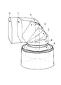
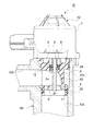
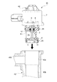
従来、この種の技術として、例えば、下記の特許文献1に記載されるポペット式の排気還流弁(EGRバルブ)が知られている。図23に断面図により示すように、このEGRバルブ61は、EGRガスの流路62を含むハウジング63と、流路62に設けられた弁座64と、弁座64に着座可能に設けられた弁体65と、弁体65が一端部に設けられた弁軸66と、弁体65と共に弁軸66を往復駆動するための駆動部67とを備える。ハウジング63の流路62は、入口68と出口69を含む。図24に、流路62の外観とその流路62における第1流路位置A〜第7流路位置Gを斜視図により示す。図24に示す流路62は、弁座64より下流が入口68の方向に対し直交する方向に屈曲した屈曲流路部62a(2点鎖線で示す)を含む。
Conventionally, as a technique of this kind, for example, a poppet type exhaust gas recirculation valve (EGR valve) described in Patent Document 1 below is known. As shown by a cross-sectional view in FIG. 23, the
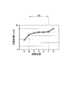
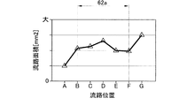
図25に、図24に示す流路62の各流路位置A〜Gの流路面積の変化をグラフにより示す。このグラフは、横軸に各流路位置A〜Gを、縦軸に流路面積を示す。図24、図25に示すように、弁座64より下流の流路62は、その流路面積が一旦増加(第2流路位置B〜第4流路位置D)してから減少(第4流路位置D〜第6流路位置F)し、再び増加(第6流路位置F及び第7流路位置G)する形状を有することがわかる。
FIG. 25 is a graph showing changes in the flow path area of each flow path position A to G of the
ところで、特許文献1に記載されたEGRバルブ61では、弁座64より下流の流路62の形状について問題があった。すなわち、この流路62の流路面積が、下流方向へ向けて一旦増加してから減少し、再び増加する形状を有するので、流路62における圧損が大きくなる傾向があった。このため、その圧損が大きくなる分だけEGRガスの最大流量を増加させることができなかった。ここで、流路62におけるEGRガスの最大流量を増加させるには、弁座64と弁体65の径を大きくすることが考えられるが、弁座64と弁体65の径を大きくしてはEGRバルブ61が大型化してしまう。
By the way, in the
この開示技術は、上記事情に鑑みてなされたものであって、その目的は、弁座と弁体の径を大きくするなどEGRバルブの体格を大きくすることなくEGRガスの最大流量を増加させることを可能としたEGRバルブ及びそれを備えたEGRバルブ装置を提供することにある。 This disclosure technique was made in view of the above circumstances, and its purpose is to increase the maximum flow rate of EGR gas without increasing the physique of the EGR valve such as increasing the diameter of the valve seat and the valve body. It is an object of the present invention to provide an EGR valve capable of the above and an EGR valve device including the EGR valve.
上記目的を達成するために、請求項1に記載の技術は、EGRガスの流路を含むハウジングと、流路に設けられた弁座と、流路は、入口と出口を有し、弁座より下流に入口へ向かう方向に対し直交する方向に屈曲した屈曲流路部を含むことと、弁座に着座可能に設けられた弁体と、弁体が一端部に設けられた弁軸と、弁軸を往復駆動するための駆動部とを備えたポペット式のEGRバルブにおいて、屈曲流路部は、その流路面積が下流方向に向けて一定となる部分及び流路面積が下流方向に向けて増加する部分の少なくとも一方のみを含むことを趣旨とする。 In order to achieve the above object, the technique according to claim 1 has a housing including an EGR gas flow path, a valve seat provided in the flow path, and the flow path has an inlet and an outlet, and the valve seat. It includes a bent flow path portion that is bent in a direction orthogonal to the direction toward the inlet further downstream, a valve body that can be seated on the valve seat, and a valve shaft that is provided at one end of the valve body. In a poppet-type EGR valve provided with a drive unit for reciprocating the valve shaft, the bent flow path portion has a portion where the flow path area is constant in the downstream direction and a flow path area in the downstream direction. The purpose is to include at least one of the increasing parts.
上記技術の構成によれば、ハウジングの流路を構成する屈曲流路部は、その流路面積が下流方向に向けて一定となる部分及びその流路面積が下流方向に向けて増加する部分の少なくとも一方のみを含み、流路面積が下流方向に向けて減少する部分を含まないので、屈曲流路部における圧損が低減する。 According to the configuration of the above technique, the bent flow path portion constituting the flow path of the housing is a portion in which the flow path area is constant in the downstream direction and a portion in which the flow path area increases in the downstream direction. Since it includes at least one of them and does not include a portion where the flow path area decreases in the downstream direction, the pressure loss in the bent flow path portion is reduced.
上記目的を達成するために、請求項2に記載の技術は、請求項1に記載の技術において、流路面積が下流方向に向けて増加する部分は、流路面積が緩やかに変化することを趣旨とする。 In order to achieve the above object, the technique according to claim 2 states that in the technique according to claim 1, the flow path area gradually changes in the portion where the flow path area increases in the downstream direction. The purpose.
上記技術の構成によれば、請求項1に記載の技術の作用に加え、屈曲流路部の流路面積が下流方向に向けて増加する部分では、流路面積が緩やかに変化するので、EGRガスが下流方向へ向けて滑らかに流れる。 According to the configuration of the above technique, in addition to the action of the technique according to claim 1, the flow path area gradually changes in the portion where the flow path area of the bent flow path portion increases in the downstream direction, so that EGR The gas flows smoothly in the downstream direction.
上記目的を達成するために、請求項3に記載の技術は、請求項1又は2に記載の技術において、ハウジングは、少なくとも屈曲流路部を有する部分が樹脂材で構成されることを趣旨とする。
In order to achieve the above object, the technique according to
上記技術の構成によれば、請求項1又は2に記載の技術の作用に加え、ハウジングの、少なくとも屈曲流路部を有する部分が樹脂材で構成されるので、金属材で構成されるハウジングに比べてハウジングの薄肉化が可能になると共に、流路で発生する凝縮水に対しハウジングの耐腐食性が増す。
According to the configuration of the above technique, in addition to the action of the technique according to
上記目的を達成するために、請求項4に記載の技術は、請求項1乃至3のいずれかに記載の技術において、弁座より下流の流路は、屈曲流路部と、屈曲流路部より下流にて出口に続く出口流路部とを含み、ハウジングは、出口流路部と、出口流路部と交差する嵌入孔とを有する外ハウジングと、外ハウジングの嵌入孔に嵌め入れられ、屈曲流路部と、弁座より上流にて入口に続く入口流路部とを有する内ハウジングとを含み、外ハウジングの嵌入孔と内ハウジングの外周との間にシール部材が設けられることを趣旨とする。
In order to achieve the above object, the technique according to
上記技術の構成によれば、請求項1乃至3のいずれかに記載の技術の作用に加え、ハウジングが外ハウジングと内ハウジングの二体で構成されるので、外ハウジングと内ハウジングに別々の機能を持たせることが可能となる。例えば、流路を拡大するために樹脂材で構成される内ハウジングを薄肉化し、強度確保のために外ハウジングを金属材で構成することなどが可能となる。また、外ハウジングと内ハウジングとの間にシール部材が設けられるので、外ハウジングと内ハウジングとの間へのEGRガスの浸入が抑えられる。 According to the configuration of the above technique, in addition to the operation of the technique according to any one of claims 1 to 3, since the housing is composed of two bodies, the outer housing and the inner housing, the outer housing and the inner housing have different functions. It becomes possible to have. For example, it is possible to thin the inner housing made of a resin material in order to expand the flow path, and to make the outer housing made of a metal material in order to secure the strength. Further, since the sealing member is provided between the outer housing and the inner housing, the infiltration of EGR gas between the outer housing and the inner housing is suppressed.
上記目的を達成するために、請求項5に記載の技術は、請求項1乃至4のいずれかに記載のEGRバルブと、EGRバルブのハウジングが組み付けられる相手部材とを備えたEGRバルブ装置において、相手部材は、組み付け孔と、別の流路とを含み、ハウジングが相手部材の組み付け孔に組み付けられた状態で、ハウジングの入口と出口が別の流路に連通することを趣旨とする。
In order to achieve the above object, the technique according to
上記技術の構成によれば、請求項1乃至4のいずれかに記載の技術の作用に加え、EGRバルブのハウジングを相手部材の組み付け孔に組み付けることで、EGRバルブが相手部材に取り付けられる。従って、EGRバルブから、取り付け用の付属構成が省略され、その分だけ省スペースとなる。また、EGRバルブを共通化して各種相手部材の組み付け孔に組み付けることが可能となる。 According to the configuration of the above technique, in addition to the operation of the technique according to any one of claims 1 to 4, the EGR valve is attached to the mating member by assembling the housing of the EGR valve into the assembling hole of the mating member. Therefore, the accessory configuration for mounting is omitted from the EGR valve, and the space is saved accordingly. In addition, the EGR valve can be shared and assembled into the assembly holes of various mating members.
請求項1に記載の技術によれば、EGRバルブにつき、弁座と弁体の径を大きくするなどEGRバルブの体格を大きくすることなくEGRガスの最大流量を増加させることができる。 According to the technique according to claim 1, the maximum flow rate of the EGR gas can be increased for the EGR valve without increasing the physique of the EGR valve such as increasing the diameter of the valve seat and the valve body.
請求項2に記載の技術によれば、EGRバルブにつき、弁座と弁体の径を大きくするなどEGRバルブの体格を大きくすることなくEGRガスの最大流量を増加させることができる。
According to the technique according to
請求項3に記載の技術によれば、請求項1又は2に記載の技術の効果に加え、EGRバルブの流路の拡大と流量特性の安定性の向上を図ることができる。
According to the technique of
請求項4に記載の技術によれば、請求項1乃至3のいずれかに記載の技術の効果に加え、EGRバルブにつき、最小限の体格で機能を確保することができ、延いてはEGRバルブの体格を大きくすることなく流路を拡大することができる。
According to the technique according to
請求項5に記載の技術によれば、請求項1乃至4のいずれかに記載の技術の効果に加え、EGRバルブにつき、省スペース化の分だけ流路の拡大を図ることができると共に、各種相手部材に対するEGRバルブの汎用性を向上させることができる。
According to the technique according to
以下、EGRバルブ及びそれを備えたEGRバルブ装置を具体化したいくつかの実施形態につき図面を参照して詳細に説明する。 Hereinafter, some embodiments embodying the EGR valve and the EGR valve device including the EGR valve will be described in detail with reference to the drawings.
<第1実施形態>
先ず、EGRバルブを具体化した第1実施形態について説明する。
<First Embodiment>
First, a first embodiment in which the EGR valve is embodied will be described.
[EGRバルブの構成について]
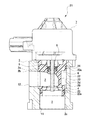
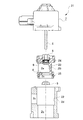
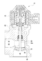
図1に、この実施形態のEGRバルブ1を一部切断した正面図により示す。図2に、ハウジング3の一部を流路2の出口12の側から視た図により示す。EGRバルブ1は、エンジンから排気通路へ排出される排気の一部をEGRガスとしてエンジンへ還元するために吸気通路へ流すEGR通路(図示略)に設けられる。EGRバルブ1は、EGR通路におけるEGRガスの流量を調節するために使用される。
[About EGR valve configuration]
FIG. 1 shows a front view of the EGR valve 1 of this embodiment partially cut. FIG. 2 shows a part of the
図1に示すように、EGRバルブ1は、ポペット式のバルブ構造を有し、EGRガスの流路2を含むハウジング3と、流路2の中間に設けられた環状の弁座4と、弁座4に着座可能に設けられた略傘形状の弁体5と、弁体5が一端部に設けられた弁軸6と、弁軸6を弁体5と共に往復駆動するための駆動部7とを備える。駆動部7は、例えば、DCモータにより構成することができる。図1では、駆動部7以外を断面図により示す。弁座4は、ハウジング3とは別に形成され、流路2の途中に組み付けられる。ハウジング3は、樹脂材により構成され、弁座4と弁体5は金属材により構成される。弁座4と弁体5の形状は一例である。このEGRバルブ1は、弁体5を弁座4に対し移動させて弁座4との間の開度を変化させることにより、流路2におけるEGRガスの流量を調節するようになっている。この実施形態では、駆動部7の詳しい説明は省略する。
As shown in FIG. 1, the EGR valve 1 has a poppet-type valve structure, and has a
図1に示すように、弁軸6は、駆動部7から下方へ伸び、ハウジング3に対し垂直に嵌め入れられる。弁軸6は弁座4の軸線と平行に配置される。弁体5は、弁軸6が往復駆動することにより、弁座4に対して着座(当接)及び離間するようになっている。ハウジング3と弁軸6との間には、弁軸6を往復動可能に支持するためのスラスト軸受8が設けられる。ハウジング3と弁軸6との間には、両者3,6の間をシールするためのリップシール9が、スラスト軸受8の下端に隣接して設けられる。この実施形態で、弁体5は弁座4の下側(上流側)にて、弁座4に着座可能に配置される。
As shown in FIG. 1, the
[流路の構成について]
図1に示すように、ハウジング3の流路2は、入口11と出口12を含む。流路2は、弁座4より上側(下流側)にて、入口11へ向かう方向に対し直交する方向に屈曲した屈曲流路部2a(2点鎖線で示す)を含む。弁座4より下流の流路2は、屈曲流路部2aの他に、屈曲流路部2aより下流にて出口12に続く出口流路部2b(2点鎖線で示す)を含む。弁座4より上流の流路2は、入口11に続く入口流路部2c(2点鎖線で示す)を含む。
[About the structure of the flow path]
As shown in FIG. 1, the
図3に、ハウジング3の流路2の一部の外観とその流路2における第1流路位置A〜第7流路位置Gを斜視図により示す。図3において、「A〜F」は、ハウジング3の流路2のうち、弁座4の入口11から流路2の出口12までの間の異なる流路位置を示す。ここで、第1流路位置Aは、弁座4の入口の位置に対応し、第2流路位置Bは、弁座4の出口の位置であって屈曲流路部2aの入口の位置に対応する。第6流路位置Fは、屈曲流路部2aの出口の位置に対応する。第3流路位置C〜第5流路位置Eは、屈曲流路部2aの中間における異なる位置を示す。第7流路位置Gは、流路2の出口12の位置に対応する。
FIG. 3 shows the appearance of a part of the
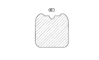
図4〜図8に、第2流路位置B〜第6流路位置Fにおける流路断面をそれぞれ示す。図9に、第1流路位置A〜第7流路位置Gの流路面積の変化をグラフにより示す。図9において、第2流路位置B〜第6流路位置Fまでが屈曲流路部2aに対応する。第2流路位置B〜第7流路位置Gにおける流路面積は、いずれも第2流路位置Bの流路面積よりも大きく、かつ徐々に大きくなっていることがわかる。ここで、第2流路位置B〜第6流路位置Fまでの屈曲流路部2aでは、その流路面積が、下流方向に向けて増加する部分(第2流路位置B〜第4流路位置D)と下流方向に向けて一定となる部分(第4流路位置D〜第6流路位置F)の両方のみを含み、流路面積が下流方向に向けて減少する部分を含まないように設定される。また、この屈曲流路部2aにおいて、流路面積が下流方向に向けて増加する部分(第2流路位置B〜第4流路位置D)は、流路面積が緩やかに変化するように設定される。
4 to 8 show the cross sections of the flow paths at the second flow path position B to the sixth flow path position F, respectively. FIG. 9 is a graph showing changes in the flow path area of the first flow path position A to the seventh flow path position G. In FIG. 9, the second flow path position B to the sixth flow path position F correspond to the bending
[EGRバルブの作用及び効果について]
以上説明したこの実施形態のEGRバルブ1の構成によれば、駆動部7により弁軸6を弁体5と共に駆動させ、弁体5を弁座4に対し移動させる。これにより、弁座4と弁体5との間の開口面積(開度)が変化し、流路2におけるEGRガスの流量が調節される。ここで、このEGRバルブ1の構成によれば、ハウジング3の流路2を構成する屈曲流路部2aは、その流路面積が下流方向に向けて増加する部分(第2流路位置B〜第4流路位置D)及びその流路面積が下流方向に向けて一定となる部分(第4流路位置D〜第6流路位置F)の両方のみを含み、流路面積が下流方向に向けて減少する部分を含まない。従って、屈曲流路部2aにおける圧損が低減する。このため、EGRバルブ1につき、弁座4と弁体5の径を大きくするなどEGRバルブ1の体格を大きくすることなくEGRガスの最大流量を増加させることができる。
[About the action and effect of EGR valve]
According to the configuration of the EGR valve 1 of this embodiment described above, the
この実施形態の構成によれば、屈曲流路部2aの流路面積が下流方向に向けて増加する部分(第2流路位置B〜第4流路位置D)では、流路面積が緩やかに変化するので、EGRガスが下流方向へ向けて滑らかに流れる。この意味でも、EGRバルブ1につき、弁座4と弁体5の径を大きくするなどEGRバルブ1の体格を大きくすることなくEGRガスの最大流量を増加させることができる。
According to the configuration of this embodiment, the flow path area is gentle in the portion where the flow path area of the bent
ここで、従来例のEGRバルブにつき、EGRガスの流量係数と最大流量を計測したところ、一例として、流量係数が「0.61」となり、最大流量が「720(リットル/分)」となった。これに対し、弁座4と弁体5の径を従来例と同一とした本実施形態のEGRバルブ1につき、EGRガスの流量係数と最大流量を計測したところ、一例として、流量係数が「0.84」となり、最大流量が「890(リットル/分)」となった。すなわち、本実施形態では、従来例に対し、弁座4及び弁体5の径を大きくすることなく最大流量を「23%」増加させることができた。
Here, when the flow coefficient and the maximum flow rate of the EGR gas were measured for the EGR valve of the conventional example, the flow coefficient was "0.61" and the maximum flow rate was "720 (liters / minute)" as an example. .. On the other hand, when the flow coefficient and the maximum flow rate of the EGR gas were measured for the EGR valve 1 of the present embodiment in which the diameters of the
また、この実施形態の構成によれば、流路2を含むハウジング3が樹脂材で構成されるので、金属材で構成されるハウジングに比べてハウジング3の薄肉化が可能になると共に、流路2で発生する凝縮水に対しハウジング3の耐腐食性が増す。このため、EGRバルブ1の流路2の拡大と流量特性の向上を図ることができる。
Further, according to the configuration of this embodiment, since the
<第2実施形態>
次に、EGRバルブを具体化した第2実施形態について説明する。なお、以下の説明において、第1実施形態と同等の構成については同一の符号を付して説明を省略し、以下には異なった点を中心に説明する。
<Second Embodiment>
Next, a second embodiment in which the EGR valve is embodied will be described. In the following description, the same components as those in the first embodiment are designated by the same reference numerals and the description thereof will be omitted, and the differences will be mainly described below.
[EGRバルブの構成について]
図10に、この実施形態のEGRバルブ21を一部切断した正面図により示す。図11に、EGRバルブ21を分解した一部切断した正面図により示す。この実施形態では、主としてハウジング3の構成の点で第1実施形態と異なる。
[About EGR valve configuration]
FIG. 10 shows a front view of the
図10に示すように、EGRバルブ21は、第1実施形態と形状等は多少異なるものの、同様に流路2を含むハウジング3、弁座4、弁体5、弁軸6及び駆動部7を備える。
As shown in FIG. 10, the
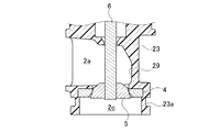
図10に示すように、ハウジング3の流路2は、その入口11から出口12へ向かう順に、入口流路部2c、屈曲流路部2a及び出口流路部2bを含む。この実施形態で、図11に示すように、ハウジング3は、外ハウジング22と内ハウジング23の二体により構成される。外ハウジング22は、出口流路部2bと、出口流路部2bと交差する嵌入孔2dとを有する。この嵌入孔2dは、弁座4より上流にて入口11に続く入口流路部2cの一部を構成する。内ハウジング23は、上記した屈曲流路部2aと、弁座4より上流にて入口11に続く入口流路部2cの一部とを含む。そして、外ハウジング22の嵌入孔2dに対し内ハウジング23が嵌め入れられることにより、ハウジング3が構成される。この実施形態で、内ハウジング23は樹脂材により構成され、外ハウジング22は金属材(例えば、アルミ)により構成される。外ハウジング22の嵌入孔2dと内ハウジング23の外周との間には、第1シール部材24と第2シール部材25が設けられる。二つのシール部材24,25は、ゴム製のOリングにより構成される。第1シール部材24は、流路2の屈曲流路部2aより上にて内ハウジング23の外周に設けられる。第2シール部材25は、弁座4より下にて内ハウジング23の外周に設けられる。両シール部材24,25とも、内ハウジング23の外周に形成された周溝23aに組み付けられる。
As shown in FIG. 10, the
図12に、EGRバルブ21の製造工程の一部を一部切断した正面図により示す。図12に示すように、このEGRバルブ21を製造するには、予め製造した駆動部7(弁軸6等を含む)、内ハウジング23、弁座4、弁体5、第1及び第2のシール部材24,25を互いに組み付けてアッセンブリ27とする。その後、このアッセンブリ27を外ハウジング22に組み付ける。すなわち、アッセンブリ27の内ハウジング23を外ハウジング22の嵌入孔2dに嵌め入れる(ドロップインする)。このとき、内ハウジング23と外ハウジング22との間で、流路2を構成する屈曲流路部2aと出口流路部2bとを連通させる。また、内ハウジング23の入口流路部2cを外ハウジング22の嵌入孔2dに連通させる。これにより、図10に示すEGRバルブ21が得られる。
FIG. 12 shows a front view in which a part of the manufacturing process of the
[流路の構成について]
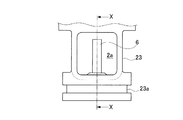
図13に、内ハウジング23の一部を屈曲流路部2aの出口側から視た図により示す。図14に、内ハウジング23を、図13のX−X線断面図により示す。図14に示すように、この実施形態において、屈曲流路部2aは、弁軸6を基準に出口12へ向かう方向と反対の方向へ凸となる窪み29を含む。
[About the structure of the flow path]
FIG. 13 shows a part of the
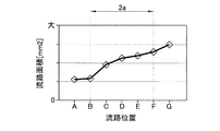
図15に、内ハウジング23の流路2の一部の外観とその流路2における第1流路位置〜第7流路位置を斜視図により示す。図15において、第1流路位置A〜第7流路位置Gは、内ハウジング23の流路2のうち、弁座4の入口から流路2の出口までの間の流路位置を示す。図16には、第1流路位置A〜第7流路位置Gの流路面積の変化をグラフにより示す。図16において、第2流路位置B〜第6流路位置Fまでが屈曲流路部2aに対応する。図16に示すように、屈曲流路部2aの第2流路位置B〜第6流路位置Fにおける流路面積は、いずれも第2流路位置Bの流路面積よりも大きく、かつ徐々に大きくなっていることがわかる。ここで、第3流路位置C〜第7流路位置Gまでの屈曲流路部2aでは、その流路面積が、下流方向に向けて増加する部分(第2流路位置B〜第6流路位置F)のみを含み、流路面積が下流方向に向けて減少する部分を含まないように設定される。また、この屈曲流路部2aにおいて、流路面積が下流方向に向けて増加する部分(第2流路位置B〜第6流路位置F)は、流路面積が比較的緩やかに変化するように設定される。
FIG. 15 is a perspective view showing the appearance of a part of the
ここで、屈曲流路部2aの窪み29は、内ハウジング23の製造時に、滑らかな内面を有する屈曲流路部2aを金型により成形するために便宜的にできるものであるが、最小限の大きさに設定することが好ましい。
Here, the
[EGRバルブの作用及び効果について]
以上説明したこの実施形態のEGRバルブ21の構成によれば、第1実施形態の作用及び効果に加え、次のような作用及び効果を得ることができる。すなわち、ハウジング3が外ハウジング22と内ハウジング23の二体で構成されるので、外ハウジング22と内ハウジング23に別々の機能を持たせることが可能となる。例えば、流路2を拡大するために樹脂材で構成される内ハウジング23を薄肉化し、強度確保のために外ハウジング22を金属材で構成することなどが可能となる。また、外ハウジング22と内ハウジング23との間にシール部材24,25が設けられるので、外ハウジング22と内ハウジング23との間へのEGRガスの浸入が抑えられる。このため、EGRバルブ21につき、最小限の体格で機能を確保することができ、延いてはEGRバルブ21の体格を大きくすることなく流路2を拡大することができる。
[About the action and effect of EGR valve]
According to the configuration of the
また、この実施形態の構成によれば、ハウジング3が、樹脂材よりなる内ハウジング23と、金属材よりなる外ハウジング22とから構成されるので、全体が金属材により構成されるハウジングに比べてハウジング3が軽量化する。また、流路2の大部分を構成する内ハウジング23が樹脂材により構成されるので、流路2で発生する凝縮水に対しハウジング3の耐腐食性が増す。このため、EGRバルブ21の軽量化と耐久性の向上を図ることができる。
Further, according to the configuration of this embodiment, since the
<第3実施形態>
次に、EGRバルブを具体化した第3実施形態について説明する。この実施形態では、ハウジング3の構成の点で第1実施形態と異なる。
<Third Embodiment>
Next, a third embodiment in which the EGR valve is embodied will be described. This embodiment differs from the first embodiment in that the
[EGRバルブの構成について]
図17に、樹脂材により構成されるハウジング3を斜視図により示す。図17に示すように、ハウジング3の上側には、駆動部7に接続される第1フランジ31が形成され、その下側には、EGR通路に接続される第2フランジ32が形成される。外ハウジング22の出口12の側には、EGR通路に接続される第3フランジ33が形成される。
[About EGR valve configuration]
FIG. 17 shows a
ここで、図17に示すように、第1フランジ31には、駆動部7との締結のために金属製ボルトが挿通される第1ボルト孔35が設けられる。図18には、この第1ボルト孔35の部分を断面図により示す。この実施形態では、第1フランジ31が樹脂材で構成されることから、第1ボルト孔35を補強するために、第1ボルト孔35には金属製の補強管36がインサート成形される。
Here, as shown in FIG. 17, the
また、図17に示すように、第2フランジ32には、EGR通路との接続のために金属製ボルトが挿通される第2ボルト孔37が設けられる。図19には、この第2ボルト孔37の部分を断面図により示す。この第2ボルト孔37にも、同孔37を補強するために、金属製の補強管38がインサート成形される。
Further, as shown in FIG. 17, the
図17に示すように、第3フランジ33には、EGR通路との接続のために金属製ボルトが挿通される第3ボルト孔39が設けられる。図20に、この第3ボルト孔39の部分を断面図により示す。この第3ボルト孔39にも、同孔39を補強するために、金属製の補強管40がインサート成形される。
As shown in FIG. 17, the
[EGRバルブの作用及び効果について]
以上説明したこの実施形態のEGRバルブ21の構成によれば、第1実施形態の作用及び効果に加え、次のような作用及び効果を得ることができる。すなわち、この実施形態では、樹脂材で構成されるハウジング3において、相手部材(駆動部7又はEGR通路)との接続のために設けられた各ボルト孔35,37,39が、金属製の補強管36,38,40により補強される。このため、各フランジ31〜33が、各ボルト孔35,37,39に挿通された金属製ボルトにより締め付けられても、各ボルト孔35,37,39の耐久性を高めることができ、EGRバルブ21での締結の信頼性を高めることができる。
[About the action and effect of EGR valve]
According to the configuration of the
<第4実施形態>
次に、EGRバルブを含むEGRバルブ装置を具体化した第4実施形態について説明する。
<Fourth Embodiment>
Next, a fourth embodiment in which an EGR valve device including an EGR valve is embodied will be described.
[EGRバルブ装置の構成について]
図21に、この実施形態のEGRバルブ装置41を一部切断して正面図により示す。図22に、EGRバルブ装置41を構成するEGRバルブ42とEGR通路43を分解して一部切断した正面図により示す。図21に示すように、EGRバルブ装置41は、EGRバルブ42と、EGRバルブ42のハウジング3が組み付けられる相手部材としてのEGR通路43とを備える。このEGRバルブ42のハウジング3は、第2実施形態でハウジング3を構成した樹脂製の内ハウジング23のみで構成される。EGR通路43は、組み付け孔43aと、EGRガスが流れる別の流路43bとを含む。
[About the configuration of the EGR valve device]
FIG. 21 shows a front view of the
このEGRバルブ装置41は、図22に示すように、EGRバルブ42のハウジング3を、EGR通路43の組み付け孔43aに嵌め入れる(ドロップインする)ことでEGR通路43に組み付けられる。そして、この組み付け状態において、ハウジング3の入口11と出口12が別の流路43bに連通する。
As shown in FIG. 22, the
[EGRバルブ装置の作用及び効果について]
以上説明したこの実施形態のEGRバルブ装置41の構成によれば、EGRバルブ42としては、第2及び第3の実施形態と同等の作用及び効果を得ることができる。加えて、この実施形態の構成によれば、EGRバルブ42のハウジング3をEGR通路43(相手部材)の組み付け孔43aに組み付けることで、EGRバルブ42がEGR通路43に取り付けられる。従って、EGRバルブ42から、取り付け用の付属構成が省略され、その分だけ省スペースとなる。また、このEGRバルブ42を共通化して各種相手部材の組み付け孔に組み付けることが可能となる。このため、EGRバルブ42につき、省スペース化の分だけ流路2の拡大を図ることができると共に、各種相手部材に対するEGRバルブ42の汎用性を向上させることができる。
[About the action and effect of the EGR valve device]
According to the configuration of the
なお、この開示技術は前記各実施形態に限定されるものではなく、開示技術の趣旨を逸脱することのない範囲で構成の一部を適宜変更して実施することもできる。 It should be noted that this disclosure technique is not limited to each of the above-described embodiments, and a part of the configuration may be appropriately modified and implemented within a range that does not deviate from the purpose of the disclosure technique.
(1)前記第1実施形態では、ハウジング3を樹脂材で構成したが、このハウジングを金属材(例えば、アルミ)で構成することもできる。
(1) In the first embodiment, the
(2)前記第2実施形態では、外ハウジング22を金属材で構成し、内ハウジング23を樹脂材で構成したが、外ハウジングと内ハウジングの両方を金属材で構成したり、外ハウジングと内ハウジングの両方を樹脂材で構成したりすることもできる。
(2) In the second embodiment, the
(3)前記第3実施形態では、第1ボルト孔35を金属製の補強管36で補強したり、第2ボルト孔37を金属製の補強管38により補強したり、第3ボルト孔39を金属製の補強管50により補強したりした。これに対し、ハウジング自体を高強度を有する材料で構成することで、金属製の補強管を省略してもよい。
(3) In the third embodiment, the
(4)前記第4実施形態では、EGRバルブ42を相手部材としてのEGR通路43に組み付けるように構成したが、相手部材としてはEGR通路に限られるものではなく、EGRクーラやEGRガス分配器等を相手部材として想定することもできる。
(4) In the fourth embodiment, the
この開示技術は、ガソリンエンジンやディーゼルエンジンに設けられるEGR装置をはじめ、耐凝縮水性(耐酸性、耐アルカリ性)を必要とする流量調整装置に適用することができる。 This disclosed technology can be applied to a flow rate adjusting device that requires condensation water resistance (acid resistance, alkali resistance), including an EGR device provided in a gasoline engine or a diesel engine.
1 EGRバルブ
2 流路
2a 屈曲流路部
2b 出口流路部
2c 入口流路部
2d 嵌入孔
3 ハウジング
4 弁座
5 弁体
6 弁軸
7 駆動部
11 入口
12 出口
21 EGRバルブ
22 外ハウジング
23 内ハウジング
24 第1シール部材
25 第2シール部材
41 EGRバルブ装置
42 EGRバルブ
43 EGR通路(相手部材)
43a 組み付け孔
43b 別の流路
1
Claims (5)
前記流路に設けられた弁座と、
前記流路は、入口と出口を有し、前記弁座より下流に前記入口へ向かう方向に対し直交する方向に屈曲した屈曲流路部を含むことと、
前記弁座に着座可能に設けられた弁体と、
前記弁体が一端部に設けられた弁軸と、
前記弁軸を往復駆動するための駆動部と
を備えたポペット式のEGRバルブにおいて、
前記屈曲流路部は、その流路面積が下流方向に向けて一定となる部分及び前記流路面積が下流方向に向けて増加する部分の少なくとも一方のみを含むことを特徴とするEGRバルブ。 A housing containing an EGR gas flow path and
The valve seat provided in the flow path and
The flow path has an inlet and an outlet, and includes a bent flow path portion that is bent in a direction orthogonal to the direction toward the inlet downstream of the valve seat.
A valve body that can be seated on the valve seat and
A valve shaft provided with the valve body at one end and
In a poppet type EGR valve provided with a drive unit for reciprocating the valve shaft.
The EGR valve is characterized in that the bent flow path portion includes at least one of a portion in which the flow path area is constant in the downstream direction and a portion in which the flow path area increases in the downstream direction.
前記流路面積が下流方向に向けて増加する部分は、前記流路面積が緩やかに変化することを特徴とするEGRバルブ。 In the EGR valve according to claim 1,
An EGR valve characterized in that the flow path area gradually changes in a portion where the flow path area increases in the downstream direction.
前記ハウジングは、少なくとも前記屈曲流路部を有する部分が樹脂材で構成されることを特徴とするEGRバルブ。 In the EGR valve according to claim 1 or 2.
The housing is an EGR valve characterized in that at least a portion having a bent flow path portion is made of a resin material.
前記弁座より下流の前記流路は、前記屈曲流路部と、前記屈曲流路部より下流にて前記出口に続く出口流路部とを含み、
前記ハウジングは、前記出口流路部と、前記出口流路部と交差する嵌入孔とを有する外ハウジングと、前記外ハウジングの前記嵌入孔に嵌め入れられ、前記屈曲流路部と、前記弁座より上流にて入口に続く入口流路部とを有する内ハウジングとを含み、
前記外ハウジングの前記嵌入孔と前記内ハウジングの外周との間にシール部材が設けられる
ことを特徴とするEGRバルブ。 In the EGR valve according to any one of claims 1 to 3.
The flow path downstream of the valve seat includes the bending flow path portion and an outlet flow path portion downstream from the bending flow path portion and continuing to the outlet.
The housing is fitted into an outer housing having an outlet flow path portion and an fitting hole intersecting the outlet flow path portion, and the fitting hole of the outer housing, and the bent flow path portion and the valve seat. Includes an inner housing having an inlet flow path that leads to the inlet further upstream.
An EGR valve characterized in that a sealing member is provided between the fitting hole of the outer housing and the outer periphery of the inner housing.
前記EGRバルブの前記ハウジングが組み付けられる相手部材と
を備えたEGRバルブ装置において、
前記相手部材は、組み付け孔と、別の流路とを含み、
前記ハウジングが前記相手部材の前記組み付け孔に組み付けられた状態で、前記ハウジングの前記入口と前記出口が前記別の流路に連通する
ことを特徴とするEGRバルブ装置。 The EGR valve according to any one of claims 1 to 4,
In an EGR valve device including a mating member to which the housing of the EGR valve is assembled.
The mating member includes an assembly hole and another flow path.
An EGR valve device, wherein the inlet and the outlet of the housing communicate with each other in a state where the housing is assembled in the assembly hole of the mating member.
Priority Applications (4)
| Application Number | Priority Date | Filing Date | Title |
|---|---|---|---|
| JP2019170217A JP2021046830A (en) | 2019-09-19 | 2019-09-19 | Egr valve and egr valve device having the same |
| CN202080064991.3A CN114423938B (en) | 2019-09-19 | 2020-08-18 | EGR valve and EGR valve device provided with same |
| US17/640,713 US11913412B2 (en) | 2019-09-19 | 2020-08-18 | EGR valve and EGR valve device provided with same |
| PCT/JP2020/031143 WO2021054022A1 (en) | 2019-09-19 | 2020-08-18 | Egr valve and egr valve device provided with same |
Applications Claiming Priority (1)
| Application Number | Priority Date | Filing Date | Title |
|---|---|---|---|
| JP2019170217A JP2021046830A (en) | 2019-09-19 | 2019-09-19 | Egr valve and egr valve device having the same |
Publications (1)
| Publication Number | Publication Date |
|---|---|
| JP2021046830A true JP2021046830A (en) | 2021-03-25 |
Family
ID=74878058
Family Applications (1)
| Application Number | Title | Priority Date | Filing Date |
|---|---|---|---|
| JP2019170217A Pending JP2021046830A (en) | 2019-09-19 | 2019-09-19 | Egr valve and egr valve device having the same |
Country Status (4)
| Country | Link |
|---|---|
| US (1) | US11913412B2 (en) |
| JP (1) | JP2021046830A (en) |
| CN (1) | CN114423938B (en) |
| WO (1) | WO2021054022A1 (en) |
Cited By (1)
| Publication number | Priority date | Publication date | Assignee | Title |
|---|---|---|---|---|
| JP2024057320A (en) * | 2022-10-12 | 2024-04-24 | 愛三工業株式会社 | Valve mechanism |
Families Citing this family (1)
| Publication number | Priority date | Publication date | Assignee | Title |
|---|---|---|---|---|
| JP2025092961A (en) * | 2023-12-11 | 2025-06-23 | 愛三工業株式会社 | Valve mechanism |
Citations (11)
| Publication number | Priority date | Publication date | Assignee | Title |
|---|---|---|---|---|
| JPH0942072A (en) * | 1995-07-31 | 1997-02-10 | Isuzu Motors Ltd | EGR valve of internal combustion engine |
| JP2001355519A (en) * | 2000-06-15 | 2001-12-26 | Sanwa Seiki Co Ltd | Exhaust gas re-circulating valve |
| JP2005291201A (en) * | 2004-03-09 | 2005-10-20 | Woodward Governor Co | High recovery sonic gas valve |
| JP2010071190A (en) * | 2008-09-18 | 2010-04-02 | Honda Motor Co Ltd | Egr control device for internal combustion engine |
| WO2011061795A1 (en) * | 2009-11-18 | 2011-05-26 | 三菱電機株式会社 | Exhaust gas recirculation valve, and system for attaching same |
| JP2012219684A (en) * | 2011-04-07 | 2012-11-12 | Denso Corp | Exhaust gas control valve |
| JP2014114715A (en) * | 2012-12-07 | 2014-06-26 | Aisan Ind Co Ltd | Exhaust gas recirculation valve |
| JP2014142136A (en) * | 2013-01-24 | 2014-08-07 | Pacific Ind Co Ltd | Electric expansion valve |
| JP2014211189A (en) * | 2013-04-18 | 2014-11-13 | 株式会社デンソー | Exhaust device for internal combustion engine |
| JP2015017506A (en) * | 2013-07-09 | 2015-01-29 | 三菱電機株式会社 | Exhaust gas recirculation valve |
| JP2015094275A (en) * | 2013-11-12 | 2015-05-18 | 愛三工業株式会社 | Exhaust gas recirculation valve |
Family Cites Families (15)
| Publication number | Priority date | Publication date | Assignee | Title |
|---|---|---|---|---|
| US3385052A (en) * | 1965-12-01 | 1968-05-28 | Outboard Marine Corp | Exhaust system |
| US3981283A (en) * | 1974-09-03 | 1976-09-21 | Ford Motor Company | Engine exhaust gas recirculating control |
| NL8401537A (en) * | 1984-05-11 | 1985-12-02 | Tno | SYSTEM AND APPARATUS FOR EXHAUST GAS RECIRCULATION IN COMBUSTION MACHINE. |
| US5611204A (en) * | 1993-11-12 | 1997-03-18 | Cummins Engine Company, Inc. | EGR and blow-by flow system for highly turbocharged diesel engines |
| US5511531A (en) * | 1994-05-19 | 1996-04-30 | Siemens Electric Ltd. | EGR valve with force balanced pintle |
| US6216458B1 (en) * | 1997-03-31 | 2001-04-17 | Caterpillar Inc. | Exhaust gas recirculation system |
| US6513507B2 (en) * | 2000-01-26 | 2003-02-04 | International Engine Intellectual Property Company, L.D.C. | Intake manifold module |
| US6311677B1 (en) * | 2000-03-30 | 2001-11-06 | Siemens Canada Limited | Engine mounting of an exhaust gas recirculation valve |
| JP4363176B2 (en) | 2003-12-22 | 2009-11-11 | マツダ株式会社 | Engine exhaust gas recirculation system |
| JP2015052283A (en) | 2013-09-06 | 2015-03-19 | 愛三工業株式会社 | Control device for exhaust gas recirculation valve |
| JP6143651B2 (en) * | 2013-11-14 | 2017-06-07 | 愛三工業株式会社 | Exhaust gas recirculation valve |
| US10337449B2 (en) * | 2017-01-02 | 2019-07-02 | Ford Global Technologies, Llc | Internal combustion engine with cylinder head |
| WO2021049507A1 (en) * | 2019-09-11 | 2021-03-18 | 愛三工業株式会社 | Valve device |
| JP2021067241A (en) * | 2019-10-25 | 2021-04-30 | 愛三工業株式会社 | EGR valve device |
| JP2021080889A (en) * | 2019-11-20 | 2021-05-27 | 愛三工業株式会社 | EGR valve device |
-
2019
- 2019-09-19 JP JP2019170217A patent/JP2021046830A/en active Pending
-
2020
- 2020-08-18 CN CN202080064991.3A patent/CN114423938B/en active Active
- 2020-08-18 US US17/640,713 patent/US11913412B2/en active Active
- 2020-08-18 WO PCT/JP2020/031143 patent/WO2021054022A1/en not_active Ceased
Patent Citations (11)
| Publication number | Priority date | Publication date | Assignee | Title |
|---|---|---|---|---|
| JPH0942072A (en) * | 1995-07-31 | 1997-02-10 | Isuzu Motors Ltd | EGR valve of internal combustion engine |
| JP2001355519A (en) * | 2000-06-15 | 2001-12-26 | Sanwa Seiki Co Ltd | Exhaust gas re-circulating valve |
| JP2005291201A (en) * | 2004-03-09 | 2005-10-20 | Woodward Governor Co | High recovery sonic gas valve |
| JP2010071190A (en) * | 2008-09-18 | 2010-04-02 | Honda Motor Co Ltd | Egr control device for internal combustion engine |
| WO2011061795A1 (en) * | 2009-11-18 | 2011-05-26 | 三菱電機株式会社 | Exhaust gas recirculation valve, and system for attaching same |
| JP2012219684A (en) * | 2011-04-07 | 2012-11-12 | Denso Corp | Exhaust gas control valve |
| JP2014114715A (en) * | 2012-12-07 | 2014-06-26 | Aisan Ind Co Ltd | Exhaust gas recirculation valve |
| JP2014142136A (en) * | 2013-01-24 | 2014-08-07 | Pacific Ind Co Ltd | Electric expansion valve |
| JP2014211189A (en) * | 2013-04-18 | 2014-11-13 | 株式会社デンソー | Exhaust device for internal combustion engine |
| JP2015017506A (en) * | 2013-07-09 | 2015-01-29 | 三菱電機株式会社 | Exhaust gas recirculation valve |
| JP2015094275A (en) * | 2013-11-12 | 2015-05-18 | 愛三工業株式会社 | Exhaust gas recirculation valve |
Cited By (1)
| Publication number | Priority date | Publication date | Assignee | Title |
|---|---|---|---|---|
| JP2024057320A (en) * | 2022-10-12 | 2024-04-24 | 愛三工業株式会社 | Valve mechanism |
Also Published As
| Publication number | Publication date |
|---|---|
| US11913412B2 (en) | 2024-02-27 |
| WO2021054022A1 (en) | 2021-03-25 |
| US20220316431A1 (en) | 2022-10-06 |
| CN114423938A (en) | 2022-04-29 |
| CN114423938B (en) | 2024-05-14 |
Similar Documents
| Publication | Publication Date | Title |
|---|---|---|
| KR20170042241A (en) | Compressor recirculation valve with noise-suppressing muffler | |
| JP2021067241A (en) | EGR valve device | |
| WO2021054022A1 (en) | Egr valve and egr valve device provided with same | |
| US10215089B2 (en) | Variable-flow-rate valve mechanism and turbocharger | |
| WO2021085077A1 (en) | Egr valve system | |
| US10443627B2 (en) | Vacuum producing device having a suction passageway and a discharge passageway entering through the same wall | |
| US9863292B2 (en) | Structure of air flow control valve and intake device | |
| US7744061B2 (en) | Butterfly valve with flow straightening | |
| JP3908846B2 (en) | Connection structure of resin parts | |
| US11781666B2 (en) | Control valve | |
| JP2008248824A (en) | Electronic throttle | |
| JPH09126093A (en) | Fuel injection valve for internal combustion engine | |
| US7406954B2 (en) | Fuel pump check valve | |
| US20220389890A1 (en) | Egr valve device | |
| JP2002004895A (en) | Throttle body | |
| US10753288B2 (en) | Throttle valve housing for a throttle valve arrangement for an internal combustion engine | |
| US11353114B1 (en) | Control valve | |
| US20180238336A1 (en) | Compressor recirculation valve with valve seat structure for suppressing noise upon opening of valve | |
| US20200116083A1 (en) | Turbocharger | |
| JP2022028357A (en) | Valve device | |
| JP2015124813A (en) | Valve assembly | |
| JP2000199460A (en) | Intake manifold | |
| JP2008019710A (en) | Second air valve | |
| JPH0610672U (en) | Check valve for negative pressure booster | |
| US11131269B2 (en) | Steel piston for an internal combustion engine |
Legal Events
| Date | Code | Title | Description |
|---|---|---|---|
| A621 | Written request for application examination |
Free format text: JAPANESE INTERMEDIATE CODE: A621 Effective date: 20211123 |
|
| A131 | Notification of reasons for refusal |
Free format text: JAPANESE INTERMEDIATE CODE: A131 Effective date: 20220712 |
|
| A131 | Notification of reasons for refusal |
Free format text: JAPANESE INTERMEDIATE CODE: A131 Effective date: 20221122 |
|
| A02 | Decision of refusal |
Free format text: JAPANESE INTERMEDIATE CODE: A02 Effective date: 20230516 |