JP2021069251A - Rotary electric machine - Google Patents
Rotary electric machine Download PDFInfo
- Publication number
- JP2021069251A JP2021069251A JP2019195207A JP2019195207A JP2021069251A JP 2021069251 A JP2021069251 A JP 2021069251A JP 2019195207 A JP2019195207 A JP 2019195207A JP 2019195207 A JP2019195207 A JP 2019195207A JP 2021069251 A JP2021069251 A JP 2021069251A
- Authority
- JP
- Japan
- Prior art keywords
- oil passage
- stator core
- case portion
- key member
- oil
- Prior art date
- Legal status (The legal status is an assumption and is not a legal conclusion. Google has not performed a legal analysis and makes no representation as to the accuracy of the status listed.)
- Granted
Links
Images


Classifications
-
- Y—GENERAL TAGGING OF NEW TECHNOLOGICAL DEVELOPMENTS; GENERAL TAGGING OF CROSS-SECTIONAL TECHNOLOGIES SPANNING OVER SEVERAL SECTIONS OF THE IPC; TECHNICAL SUBJECTS COVERED BY FORMER USPC CROSS-REFERENCE ART COLLECTIONS [XRACs] AND DIGESTS
- Y02—TECHNOLOGIES OR APPLICATIONS FOR MITIGATION OR ADAPTATION AGAINST CLIMATE CHANGE
- Y02T—CLIMATE CHANGE MITIGATION TECHNOLOGIES RELATED TO TRANSPORTATION
- Y02T10/00—Road transport of goods or passengers
- Y02T10/60—Other road transportation technologies with climate change mitigation effect
- Y02T10/64—Electric machine technologies in electromobility
Landscapes
- Iron Core Of Rotating Electric Machines (AREA)
- Motor Or Generator Frames (AREA)
- Motor Or Generator Cooling System (AREA)
Abstract
【課題】ステータコアとケース部との径方向の間にキー部材を設ける場合にも、油によるステータコアに対する冷却性能が低下するのを防止することが可能な回転電機を提供する。【解決手段】この回転電機100は、ロータ1およびステータコア21を収容するケース部3と、ケース部3に対するステータコア21の周方向の位置決めをするキー部材4と、を備える。ケース部3には、周方向に沿って形成され、ステータコア21を冷却するための油Lqを流通させる油路51が設けられている。キー部材4には、油路51に周方向に連続するように設けられ、油Lqを周方向に流通させる油路52が設けられている。【選択図】図5PROBLEM TO BE SOLVED: To provide a rotary electric machine capable of preventing deterioration of cooling performance of a stator core by oil even when a key member is provided between a stator core and a case portion in a radial direction. SOLUTION: The rotary electric machine 100 includes a case portion 3 for accommodating a rotor 1 and a stator core 21, and a key member 4 for positioning the stator core 21 in the circumferential direction with respect to the case portion 3. The case portion 3 is provided with an oil passage 51 formed along the circumferential direction and through which oil Lq for cooling the stator core 21 flows. The key member 4 is provided with an oil passage 52 which is provided in the oil passage 51 so as to be continuous in the circumferential direction and allows oil Lq to flow in the circumferential direction. [Selection diagram] Fig. 5
Description
本発明は、回転電機に関する。 The present invention relates to a rotary electric machine.
従来、ステータを備える回転電機が知られている(たとえば、特許文献1参照)。 Conventionally, a rotary electric machine provided with a stator is known (see, for example, Patent Document 1).
上記特許文献1には、ステータとロータとケースとを備える回転電機が開示されている。この回転電機では、ステータのステータコアがケースに焼き嵌めにより固定されている。そして、ケースの内周面には、周方向に沿って設けられ、冷却液が流される冷却溝が形成されている。また、ステータコアには、外周面から径方向外側に突出するとともに、ケースに対する周方向の位置決めを行うための位置決め突部が設けられている。また、ケースには、位置決め突部に対応する位置に、径方向外側に窪む位置決め溝が形成されている。そして、位置決め突部と位置決め溝との間に、軸方向に冷却液を流す冷却液流路が形成されている。そして、この回転電機では、冷却溝において周方向に流れる冷却液が位置決め突部に突き当たるとともに、冷却液が位置決め突部を径方向外側に迂回するように冷却液流路に流れる。そして、冷却液流路において、冷却液が流れる方向が周方向から軸方向に変化される。
しかしながら、上記特許文献1に記載の回転電機では、冷却溝において周方向に流れる冷却液が位置決め突部に突き当たるとともに、冷却液が位置決め突部を径方向外側に迂回するように冷却液流路に流れる。このため、冷却液が位置決め突部を迂回する分、冷却液の流れが阻害されるとともに、冷却液が迂回された部分(位置決め突部)よりも径方向内側の部分においては冷却されにくくなると考えられる。この結果、位置決め突部を冷却液が迂回することに起因して、冷却液によるステータコアに対する冷却の性能が低下すると考えられる。ここで、ステータコアをケースに対して周方向の位置決めを行うために、位置決め突部に代えて、ステータコアとケースとの径方向の間にキー部材を回転電機に設けることが考えられる。しかしながら、回転電機にキー部材を設けた構成においても、キー部材を冷却液が迂回する必要が生じるので、位置決め突部が設けられた上記特許文献1に記載の回転電機と同様に、冷却液によるステータコアに対する冷却の性能が低下すると考えられる。したがって、ステータコアとケース(ケース部)との径方向の間にキー部材を設ける場合にも、冷却液(冷却するための油)によるステータコアに対する冷却性能が低下するのを防止することが可能な回転電機が望まれている。
However, in the rotary electric machine described in
この発明は、上記のような課題を解決するためになされたものであり、この発明の1つの目的は、ステータコアとケース部との径方向の間にキー部材を設ける場合にも、油によるステータコアに対する冷却性能が低下するのを防止することが可能な回転電機を提供することである。 The present invention has been made to solve the above-mentioned problems, and one object of the present invention is to provide an oil-based stator core even when a key member is provided between the stator core and the case portion in the radial direction. It is an object of the present invention to provide a rotary electric machine capable of preventing the cooling performance from being deteriorated.
上記目的を達成するために、この発明の一の局面における回転電機は、ロータと、ロータの径方向外側に対向して配置されるステータコアを有するステータと、ロータおよびステータコアを収容するケース部と、ケース部とステータコアとの径方向の間に配置されるとともに、ケース部に対する前記ステータコアの周方向の位置決めをするキー部材と、を備え、ケース部には、周方向に沿って形成され、ステータコアを冷却するための油を流通させるケース部油路が設けられており、キー部材には、ケース部油路に周方向に連続するとともに、ステータコアを冷却するための油を周方向に流通させるキー部材油路が設けられている。 In order to achieve the above object, the rotary electric machine according to one aspect of the present invention includes a rotor, a stator having a stator core arranged so as to face the radial outer side of the rotor, and a case portion for accommodating the rotor and the stator core. A key member that is arranged between the case portion and the stator core in the radial direction and that positions the stator core in the circumferential direction with respect to the case portion is provided, and the case portion is formed along the circumferential direction to provide the stator core. A case oil passage for circulating oil for cooling is provided, and the key member is continuous with the case oil passage in the circumferential direction and is a key member for circulating oil for cooling the stator core in the circumferential direction. An oil passage is provided.
この発明の一の局面における回転電機では、上記のように、ケース部油路に周方向に連続するとともに、ステータコアを冷却するための油を周方向に流通させるキー部材油路を、キー部材に設ける。これにより、回転電機にキー部材が設けられる場合でも、周方向に油を流通させるケース部油路に周方向に連続するキー部材油路により、周方向に油を流通させる(油がキー部材を周方向に通過する)ことができる。この結果、キー部材を設ける場合でも、キー部材に対して油を迂回させることが不要になるので、油の流れが阻害されるのを防止することができるとともに、キー部材油路を流れる油によりキー部材の径方向内側の部分(ステータコア)を冷却することができる。この結果、ステータコアとケース部との径方向の間にキー部材を設ける場合にも、ステータコアを冷却するための油によるステータコアに対する冷却性能が低下するのを防止することができる。 In the rotary electric machine according to one aspect of the present invention, as described above, the key member oil passage that is continuous with the oil passage of the case portion in the circumferential direction and that allows oil for cooling the stator core to flow in the circumferential direction is used as the key member. Provide. As a result, even when the rotary electric machine is provided with the key member, the oil is circulated in the circumferential direction through the key member oil passage that is continuous in the circumferential direction to the case portion oil passage that circulates the oil in the circumferential direction (oil causes the key member). Can pass in the circumferential direction). As a result, even when the key member is provided, it is not necessary to divert the oil to the key member, so that it is possible to prevent the oil flow from being obstructed and the oil flowing through the key member oil passage can be used. The radial inner part (stator core) of the key member can be cooled. As a result, even when the key member is provided between the stator core and the case portion in the radial direction, it is possible to prevent the cooling performance of the stator core from being deteriorated by the oil for cooling the stator core.
本発明によれば、ステータコアとケース部との径方向の間にキー部材を設ける場合にも、ステータコアを冷却するための油によるステータコアに対する冷却性能が低下するのを防止することができる。 According to the present invention, even when the key member is provided between the stator core and the case portion in the radial direction, it is possible to prevent the cooling performance of the stator core from being deteriorated by the oil for cooling the stator core.
以下、本発明の実施形態を図面に基づいて説明する。 Hereinafter, embodiments of the present invention will be described with reference to the drawings.
[第1実施形態]
(回転電機の構成)
図1〜図5を参照して、第1実施形態による回転電機100の構成について説明する。
[First Embodiment]
(Structure of rotating electric machine)
The configuration of the rotary
本願明細書では、「軸方向」とは、ロータ1(ステータ2)の回転軸線(中心軸線C1)に沿った方向を意味し、図中のZ方向を意味する。また、「径方向」とは、ロータ1の径方向を意味し、「径方向内側」は、図中のR1方向、「径方向外側」は図中のR2方向を意味する。また、「周方向」は、ロータ1の周方向(E1方向またはE2方向)を意味する。
In the present specification, the "axial direction" means a direction along the rotation axis (central axis C1) of the rotor 1 (stator 2), and means the Z direction in the drawing. Further, the "diameter direction" means the radial direction of the
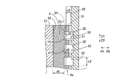
図1に示すように、回転電機100は、ロータ1とステータ2とケース部3とキー部材4とを備える。たとえば、回転電機100は、モータ、ジェネレータ、または、モータ兼ジェネレータとして構成されており、車両に搭載されるように構成されている。また、ロータ1およびステータ2は、それぞれ、円環状に形成されている。そして、ロータ1は、ステータ2の径方向内側に対向して配置されている。すなわち、第1実施形態では、回転電機100は、インナーロータ型の回転電機として構成されている。
As shown in FIG. 1, the rotary
(ステータの構成)
ステータ2は、ステータコア21と、ステータコア21に配置されたコイル22とを含む。ステータコア21は、たとえば、複数の電磁鋼板(珪素鋼板)が軸方向に積層されており、磁束を通過可能に構成されている。また、ステータコア21は、バックヨーク21aと、バックヨーク21aから径方向内側に突出する複数のティース部21bと、周方向に隣り合うティース部21bの間に形成されるスロット部21cとを含む。
(Constituent configuration)
The
図2に示すように、ステータコア21には、キー部材4が配置されるコアキー溝部23が設けられている。具体的には、コアキー溝部23は、ステータコア21の外周面24に対して径方向内側に窪むように形成されている。また、コアキー溝部23は、ステータコア21の軸方向の一方側の端面21dから軸方向の他方側の端面21eに亘って形成されている。また、図3に示すように、コアキー溝部23の外周面24に対する窪み深さは、d1である。そして、図1に示すように、コアキー溝部23は、軸方向に見て、中心軸線C1を中心で同一の径方向位置において、等角度間隔に設けられている。
As shown in FIG. 2, the
コイル22は、複数のティース部21bに巻回されている。そして、コイル22は、各スロット部21cに配置されている。そして、コイル22は、外部の電源部に接続されており、電力(たとえば、3相交流の電力)が供給されるように構成されている。そして、コイル22は、電力が供給されることにより、磁界を発生させるように構成されている。なお、図1では、コイル22の一部のみを図示しているが、コイル22は、ステータコア21の全周に亘って配置されている。
The
(ケース部の構成)
図1に示すように、ケース部3は、ロータ1およびステータコア21を収容するように構成されている。また、ケース部3は、ケース部3の内周面31の少なくとも一部がステータコア21の外周面24を支持するように配置されている。そして、ステータコア21は、ケース部3に対して隙間嵌めされた状態で、ケース部3内に収容されている。すなわち、図3に示すように、ケース部3の内周面31とステータコア21の外周面24との径方向の間(のうちの少なくとも一部)には、隙間CL1が設けられている。
(Case configuration)
As shown in FIG. 1, the
また、第1実施形態では、ケース部3は、油路51が形成された単一の部材(ケース部材)から構成されている。たとえば、ケース部3は、アルミ合金からなり、鋳造により構成されている。また、油路51は、ケース部3の周方向に沿って形成され、ステータコア21を冷却するための油Lq(図5参照)を流通させるように構成されている。また、油Lqは、たとえば、ATF(Automatic Transmission Fluid)である。なお、油路51の詳細な説明は後述する。また、油路51は、特許請求の範囲の「ケース部油路」の一例である。
Further, in the first embodiment, the
具体的には、ケース部3には、ケース部3の内周面31に対して径方向外側に窪む油路51を構成する複数の溝部32が形成されている。また、複数の溝部32は、内周面31に沿って、周方向に延びるように形成されている。そして、複数の溝部32は、後述するケース部キー溝部35により互いに周方向に隔てて設けられている。すなわち、複数の溝部32は、周方向に互いに分断されている。たとえば、図1に示すように、軸方向に見て、3つのケース部キー溝部35により周方向に3つの溝部32に分断されている。たとえば、溝部32は、鋳造されたケース部3に対して、切削加工を施すことにより形成されている。また、溝部32の内周面31に対する径方向の溝深さ(底部までの深さ)は、d2である。溝部32は、たとえば、矩形状に形成されている。なお、溝部32は、矩形状に限られず、U字状(円弧状)等に形成されていてもよい。なお、溝部32は、特許請求の範囲の「油路用溝部」の一例である。
Specifically, the
また、ケース部3には、油Lqを外部から油路51に供給するための供給口33が設けられている。たとえば、供給口33は、ケース部3を径方向に貫通する貫通孔として形成されている。また、ケース部3には、油Lqを油路51から外部に排出するための排出口34が設けられている。たとえば、排出口34は、ケース部3を径方向に貫通する貫通孔として形成されている。たとえば、供給口33は、ケース部3のうちの軸方向一方側の部分に設けられ、排出口34は、ケース部3のうちの軸方向他方側の部分に設けられている。
Further, the
また、ケース部3には、キー部材4が配置されるケース部キー溝部35が設けられている。具体的には、ケース部キー溝部35は、ケース部の内周面31に対して径方向内側に窪むように形成されている。また、ケース部キー溝部35の内周面31に対する窪み深さは、d3である。たとえば、ケース部キー溝部35の窪み深さd3は、溝部32の溝深さd2よりも大きい。また、ケース部キー溝部35は、コアキー溝部23に径方向に対向する位置に形成されている。
Further, the
(キー部材の構成)
図2に示すように、キー部材4は、ケース部3およびステータコア21とは別個に設けられている。そして、キー部材4は、ケース部3とステータコア21との径方向の間に配置されるとともに、ケース部3に対するステータコア21の周方向の位置決め(位相決め)をする機能を有する。
(Structure of key member)
As shown in FIG. 2, the
また、キー部材4は、軸方向に延びる柱状に形成されている。たとえば、キー部材4は、ステータコア21の軸方向の一方側の端面21d(の近傍)から軸方向の他方側の端面21e(の近傍)に亘って形成されている。そして、第1実施形態では、キー部材4は、ステータコア21の外周面24よりも径方向内側の位置から外周面24よりも径方向外側の位置に跨るように配置されている。すなわち、キー部材4は、ステータコア21の外周面24およびケース部3の内周面31を径方向に跨るように配置されている。詳細には、キー部材4は、ケース部キー溝部35とコアキー溝部23とに跨るように配置されている。
Further, the
図5に示すように、キー部材4には、油路51に周方向に連続するように設けられ、油Lqを周方向に流通させる油路52が設けられている。すなわち、油路52は、キー部材4に対して油Lqを周方向に通過させる機能を有する。なお、油路52は、特許請求の範囲の「キー部材油路」の一例である。
As shown in FIG. 5, the
また、キー部材4は、供給口33の周方向位置と異なる周方向位置に設けられているとともに、排出口34の周方向位置と異なる周方向位置に設けられている。具体的には、キー部材4は、軸方向に見て、中心軸線C1を中心で同一の径方向位置において、等角度間隔に複数設けられている。複数のキー部材4の各々に、油路52が設けられている。たとえば、キー部材4は、3つ設けられている。
Further, the
(油路の構成)
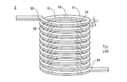
図4および図5に示すように、油路52と油路51とは、周方向に連続するように形成されている。また、油路52は、互いに周方向に隔てられた複数の溝部32(油路51)を周方向に接続するように形成されている。ここで、第1実施形態では、回転電機100は、キー部材4の油路52がケース部3の油路51に周方向に連続することにより、ステータコア21の外周面24の全周を取り囲むように油路5が形成されるように構成されている。すなわち、油路5は、供給口33から、油路51および52、排出口34までに亘る、外周面24を取り囲む油Lqの流通路である。また、第1実施形態では、油路5は、油路52が油路51に周方向に連続することにより、供給口33から排出口34まで連続したらせん形状を有するように構成されている。言い換えると、油路5は、供給口33から排出口34まで一筆書き状に形成されている。
(Construction of oil passage)
As shown in FIGS. 4 and 5, the
図3に示すように、油路52は、キー部材4のうちのステータコア21の外周面24よりも径方向外側の部分4aに形成されている。すなわち、油路52は、キー部材4のうちのケース部キー溝部35に配置されている部分4aに設けられている。具体的には、キー部材4には、油路52を構成する複数の切り欠き部41が形成されている。そして、油路52は、切り欠き部41により構成されている。たとえば、切り欠き部41は、矩形状に形成されている。
As shown in FIG. 3, the
ここで、第1実施形態では、溝部32の深さd2は、切り欠き部41の深さd4よりも大きい。また、ステータコア21の軸方向において、油路52の長さL2は、油路51の長さL1以上(図4参照)である。たとえば、長さL2と長さL1とは、等しい大きさである。
Here, in the first embodiment, the depth d2 of the
[第2実施形態]
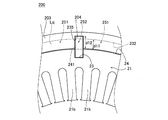
次に、図6および図7を参照して、第2実施形態による回転電機200の構成について説明する。第2実施形態では、油路52が切り欠き部41により構成されていた第1実施形態とは異なり、油路252が孔部241により構成されている。なお、上記第1実施形態と同一の構造および工程については、同じ符号(ステップ番号)を付し、その説明を省略する。
[Second Embodiment]
Next, the configuration of the rotary
第2実施形態による回転電機200は、図6に示すように、ケース部203とキー部材204とを含む。ケース部203には、油Lqを流通させる溝部232とケース部キー溝部235とが設けられている。第2実施形態では、溝部232の窪み深さd11は、ケース部キー溝部235の深さd12よりも小さい。溝部232によりステータコア21の周方向に沿って油路251が構成される。油路251の構成は、第1実施形態による油路51と同様である。
As shown in FIG. 6, the rotary
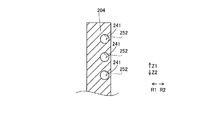
キー部材204は、コアキー溝部23とケース部キー溝部235とに跨って配置されている。そして、キー部材204には、油路252を構成する複数の孔部241が設けられている。孔部241は、溝部232に周方向に隣り合って配置されており、油路251と油路252とを連続させる機能を有する。図7に示すように、孔部241は、たとえば、円状に形成されている。なお、第2実施形態のその他の構成は、第1実施形態の構成と同様である。
The
[第1および第2実施形態の製造方法の効果]
上記第1および第2実施形態では、以下のような効果を得ることができる。
[Effects of Manufacturing Methods of First and Second Embodiments]
In the first and second embodiments, the following effects can be obtained.
第1および第2実施形態では、上記のように、ケース部油路(51、251)に周方向に連続するとともに、ステータコア(21)を冷却するための油(Lq)を周方向に流通させるキー部材油路(52、252)を、キー部材(4、204)に設ける。これにより、回転電機(100、200)にキー部材(4、204)が設けられる場合でも、周方向に油(Lq)を流通させるケース部油路(51、251)に周方向に連続するキー部材油路(52、252)により、周方向に油(Lq)を流通させる(油(Lq)がキー部材(4、204)を周方向に通過する)ことができる。この結果、キー部材(4、204)を設ける場合でも、キー部材(4、204)に対して油(Lq)を迂回させる必要がなくなるので、油(Lq)の流れが阻害されるのを防止することができるとともに、キー部材油路(52、252)を流れる油(Lq)によりキー部材(4、204)の径方向内側の部分を冷却することができる。この結果、ステータコア(21)とケース部(3、203)との径方向の間にキー部材(4、204)を設ける場合にも、ステータコア(21)を冷却するための油(Lq)によるステータコア(21)に対する冷却性能が低下するのを防止することができる。 In the first and second embodiments, as described above, the oil passages (51, 251) in the case portion are continuous in the circumferential direction, and the oil (Lq) for cooling the stator core (21) is circulated in the circumferential direction. Key member oil passages (52, 252) are provided in the key members (4, 204). As a result, even when the rotary electric machine (100, 200) is provided with the key member (4, 204), the key continuous in the circumferential direction with the case portion oil passage (51, 251) through which the oil (Lq) is circulated in the circumferential direction. The member oil passages (52, 252) allow the oil (Lq) to flow in the circumferential direction (the oil (Lq) passes through the key member (4, 204) in the circumferential direction). As a result, even when the key member (4, 204) is provided, it is not necessary to divert the oil (Lq) to the key member (4, 204), so that the flow of the oil (Lq) is prevented from being obstructed. In addition, the oil (Lq) flowing through the key member oil passages (52, 252) can cool the radial inner portion of the key member (4, 204). As a result, even when the key member (4, 204) is provided between the stator core (21) and the case portion (3, 203) in the radial direction, the stator core is made of oil (Lq) for cooling the stator core (21). It is possible to prevent the cooling performance for (21) from deteriorating.
また、第1および第2実施形態では、上記のように、ケース部(3、203)は、キー部材(4、204)の一部が配置されるケース部キー溝部(35、235)が設けられているとともに、ケース部(3、203)の内周面(31)の少なくとも一部がステータコア(21)の外周面(24)を支持するように配置されており、ケース部油路(51、251)は、ケース部キー溝部(35、235)により互いに周方向に隔てて設けられ、ケース部(3、203)の内周面(31)に対して径方向外側に窪む複数の油路用溝部(32、232)として構成されており、キー部材(4、204)には、互いに周方向に隔てられた複数の油路用溝部(32、232)を周方向に接続するように、キー部材油路(52、252)が設けられている。このように構成すれば、油路用溝部(32、232)により構成されたキー部材油路(52、252)により、ステータコア(21)を冷却するための油(Lq)をステータコア(21)の外周面(24)に接触させて直接的に冷却することができる。この結果、ケース部油路(51、251)とステータコア(21)との間に他の部材を介して、間接的に冷却する場合に比べて、冷却性能を向上させることができる。そして、上記第1および第2実施形態のように、キー部材(4、204)に、互いに周方向に隔てられた複数の油路用溝部(32、232)を周方向に接続するように、キー部材油路(52、252)を設けることにより、複数の油路用溝部(32、232)が互いに隔てられる(分断されている)場合にも、キー部材(4、204)によって油(Lq)の流動が阻害されるのを、キー部材油路(52、252)により防止することができる。 Further, in the first and second embodiments, as described above, the case portion (3, 203) is provided with the case portion key groove portion (35, 235) in which a part of the key member (4, 204) is arranged. At least a part of the inner peripheral surface (31) of the case portion (3, 203) is arranged so as to support the outer peripheral surface (24) of the stator core (21), and the case portion oil passage (51) is arranged. , 251) are provided so as to be separated from each other by a case portion key groove portion (35, 235) in the circumferential direction, and a plurality of oils recessed radially outward with respect to the inner peripheral surface (31) of the case portion (3, 203). It is configured as a road groove (32, 232), and a plurality of oil passage grooves (32, 232) separated from each other in the circumferential direction are connected to the key member (4,204) in the circumferential direction. , Key member oil passages (52, 252) are provided. With this configuration, the oil (Lq) for cooling the stator core (21) is supplied to the stator core (21) by the key member oil passages (52, 252) formed by the oil passage grooves (32, 232). It can be directly cooled by being brought into contact with the outer peripheral surface (24). As a result, the cooling performance can be improved as compared with the case of indirectly cooling the case portion oil passages (51, 251) and the stator core (21) via another member. Then, as in the first and second embodiments, the key members (4, 204) are connected in the circumferential direction to a plurality of oil passage grooves (32, 232) separated from each other in the circumferential direction. By providing the key member oil passages (52, 252), even when a plurality of oil passage grooves (32, 232) are separated (divided) from each other, the oil (Lq) is provided by the key member (4, 204). ) Can be prevented from being hindered by the key member oil passages (52, 252).
また、第1および第2実施形態では、上記のように、ステータコア(21)の外周面(24)には、ケース部キー溝部(35、235)に径方向に対向して形成されているとともに、キー部材(4、204)が配置されるコアキー溝部(23)が設けられており、キー部材(4、204)は、コアキー溝部(23)とケース部キー溝部(35、235)とに跨るように配置されており、キー部材油路(52)は、複数の油路用溝部(32、232)を周方向に接続するように、キー部材(4、204)のうちのステータコア(21)の外周面(24)よりも径方向外側の部分(4a)に形成されている。このように構成すれば、キー部材油路(52、252)をキー部材(4、204)の径方向内側の部分に形成する場合に比べて、ステータコア(21)の外周面(24)よりも径方向外側に設けられるケース部油路(51、251)の径方向の位置と、キー部材油路(52、252)の径方向の位置とをより一層近付けられるか、または、一致させることができる。この結果、油(Lq)が流れる径方向の位置の変化が小さくなる分、ケース部油路(51、251)とキー部材油路(52、252)とに渡って油(Lq)が流れる際に、油(Lq)の流動性が低下するのを防止することができる。 Further, in the first and second embodiments, as described above, the outer peripheral surface (24) of the stator core (21) is formed to face the key groove portion (35, 235) of the case portion in the radial direction. , A core key groove portion (23) in which the key member (4, 204) is arranged is provided, and the key member (4, 204) straddles the core key groove portion (23) and the case portion key groove portion (35, 235). The key member oil passage (52) is arranged so as to connect a plurality of oil passage grooves (32, 232) in the circumferential direction, so that the stator core (21) of the key members (4, 204) is connected. It is formed on a portion (4a) radially outside the outer peripheral surface (24) of the above. With this configuration, compared to the case where the key member oil passages (52, 252) are formed in the radial inner portion of the key member (4, 204), the key member oil passage (52, 252) is larger than the outer peripheral surface (24) of the stator core (21). The radial position of the case portion oil passage (51, 251) provided on the outer side in the radial direction and the radial position of the key member oil passage (52, 252) can be made closer or coincident with each other. it can. As a result, when the oil (Lq) flows over the case portion oil passage (51, 251) and the key member oil passage (52, 252) as the change in the radial position where the oil (Lq) flows becomes smaller. In addition, it is possible to prevent the fluidity of the oil (Lq) from decreasing.
また、第1および第2実施形態では、上記のように、キー部材油路(52、252)は、複数の油路用溝部(32)を周方向に接続する切り欠き部(41)、または、前記複数の油路用溝部(32)を周方向に接続する孔部(241)として形成されている。このように構成すれば、キー部材(4、204)に、切り欠き部(41)または孔部(241)を形成することによって、キー部材油路(52、252)を容易に形成することができる。 Further, in the first and second embodiments, as described above, the key member oil passages (52, 252) are notched portions (41) for connecting a plurality of oil passage groove portions (32) in the circumferential direction, or , The plurality of oil passage groove portions (32) are formed as holes (241) connecting in the circumferential direction. With this configuration, the key member oil passage (52, 252) can be easily formed by forming the notch portion (41) or the hole portion (241) in the key member (4, 204). it can.
また、第1実施形態では、上記のように、キー部材油路(52)は、切り欠き部(41)により構成されており、油路用溝部(32)の深さ(d2)は、切り欠き部(41)の深さ(d4)よりも大きい。このように構成すれば、切り欠き部(41)または孔部(241)に加えて、比較的深い溝部(32)により、油(Lq)の流動性が低下するのを、さらに防止することができる。 Further, in the first embodiment, as described above, the key member oil passage (52) is composed of the notch portion (41), and the depth (d2) of the oil passage groove portion (32) is cut. It is larger than the depth (d4) of the notch (41). With this configuration, it is possible to further prevent the fluidity of the oil (Lq) from being lowered due to the relatively deep groove portion (32) in addition to the notch portion (41) or the hole portion (241). it can.
また、第1および第2実施形態では、上記のように、ステータコア(21)の軸方向において、キー部材油路(52、252)の長さ(L2)は、ケース部油路(51、251)の長さ(L1)以上である。このように構成すれば、軸方向の長さ(L2)が大きい分、キー部材油路(52、252)内における流動性を向上させることができる。この結果、ケース部油路(51、251)を流れる油(Lq)の流動性が、キー部材油路(52、252)により低下するのをより一層防止することができる。 Further, in the first and second embodiments, as described above, the length (L2) of the key member oil passages (52, 252) in the axial direction of the stator core (21) is set to the case portion oil passages (51, 251). ) Is greater than or equal to the length (L1). With this configuration, the fluidity in the key member oil passages (52, 252) can be improved by the amount that the length (L2) in the axial direction is large. As a result, it is possible to further prevent the fluidity of the oil (Lq) flowing through the case portion oil passages (51, 251) from being lowered by the key member oil passages (52, 252).
また、第1および第2実施形態では、上記のように、キー部材油路(52、252)がケース部油路(51、251)に周方向に連続することにより、ステータコア(21)の外周面(24)の全周を取り囲むように油路(5)が形成されるように構成されている。このように構成すれば、ステータコア(21)の外周面(24)の全周を連続した油路(5)により取り囲むことができるので、ステータコア(21)を全周に亘って均一に冷却することができる。 Further, in the first and second embodiments, as described above, the key member oil passages (52, 252) are continuous with the case portion oil passages (51, 251) in the circumferential direction, whereby the outer periphery of the stator core (21) is formed. An oil passage (5) is formed so as to surround the entire circumference of the surface (24). With this configuration, the entire circumference of the outer peripheral surface (24) of the stator core (21) can be surrounded by the continuous oil passage (5), so that the stator core (21) is uniformly cooled over the entire circumference. Can be done.
また、第1および第2実施形態では、上記のように、キー部材油路(52、252)がケース部油路(51、251)に周方向に連続することにより、ステータコア(21)を冷却するための油(Lq)を供給する供給口(33)からステータコア(21)を冷却するための油(Lq)を排出する排出口(34)まで連続したらせん形状を有する油路(5)が形成されるように構成されている。このように構成すれば、らせん形状を有する油路(5)により、油(Lq)が供給口(33)から供給され、排出口(34)から排出されるまでに、複数周、油(Lq)がステータコア(21)の周りを流れる。この結果、油(Lq)がステータコア(21)の周りを1周分のみ流される場合に比べてステータコア(21)からのより多くの熱が、油(Lq)に伝達される。この結果、油(Lq)によるステータコア(21)に対する冷却性能を向上させることができる。また、ステータコア(21)の周りを1周分のみ流れる複数の油路の各々に対して、供給口および排出口を設ける場合と異なり、供給口(33)および排出口(34)の数を削減することができるので、供給口(33)および排出口(34)を構成する部品の点数を削減することができる。 Further, in the first and second embodiments, as described above, the key member oil passages (52, 252) are continuous with the case portion oil passages (51, 251) in the circumferential direction to cool the stator core (21). An oil passage (5) having a continuous spiral shape extends from a supply port (33) for supplying oil (Lq) to a discharge port (34) for discharging oil (Lq) for cooling the stator core (21). It is configured to be formed. With this configuration, the oil (Lq) is supplied from the supply port (33) by the spiral-shaped oil passage (5), and the oil (Lq) takes a plurality of turns before being discharged from the discharge port (34). ) Flow around the stator core (21). As a result, more heat from the stator core (21) is transferred to the oil (Lq) than when the oil (Lq) is flowed around the stator core (21) for only one round. As a result, the cooling performance of the oil (Lq) on the stator core (21) can be improved. Further, unlike the case where the supply port and the discharge port are provided for each of the plurality of oil passages flowing around the stator core (21) for only one round, the number of supply ports (33) and discharge ports (34) is reduced. Therefore, the number of parts constituting the supply port (33) and the discharge port (34) can be reduced.
また、第1および第2実施形態では、上記のように、キー部材(4、204)は、ステータコア(21)を冷却するための油(Lq)を供給する供給口(33)の周方向位置と異なる周方向位置に設けられているとともに、ステータコア(21)を冷却するための油(Lq)を排出する排出口(34)の周方向位置と異なる周方向位置に設けられている。このように構成すれば、キー部材(4、204)を供給口(33)または排出口(34)と同一の周方向位置に設けて、キー部材油路(52、252)に供給口(33)または排出口(34)を設ける場合と異なり、キー部材(4、204)(キー部材油路(52、252))の構成が複雑化するのを防止することができる。 Further, in the first and second embodiments, as described above, the key members (4, 204) are positioned in the circumferential direction of the supply port (33) for supplying the oil (Lq) for cooling the stator core (21). It is provided at a circumferential position different from that of the circumferential position of the discharge port (34) for discharging oil (Lq) for cooling the stator core (21). With this configuration, the key member (4,204) is provided at the same circumferential position as the supply port (33) or the discharge port (34), and the supply port (33) is provided in the key member oil passage (52, 252). ) Or the discharge port (34) is provided, and it is possible to prevent the configuration of the key member (4, 204) (key member oil passage (52, 252)) from becoming complicated.
また、第1および第2実施形態では、上記のように、ケース部(3、203)は、キー部材(4、204)の一部が配置されるケース部キー溝部(35、235)が設けられているとともに、ケース部(3、203)の内周面(31)の少なくとも一部がステータコア(21)の外周面(24)を支持するように配置されており、ステータコア(21)は、ケース部(3、203)に対して隙間嵌めされた状態で、ケース部(3、203)内に収容されている。このように構成すれば、ステータコア(21)をケース部(3、203)に対して締り嵌めを行う場合に比べて、ステータコア(21)を容易にケース部(3、203)内に収容することができる。そして、ステータコア(21)の外周面(24)とケース部(3、203)との径方向の隙間(CL1)に、ケース部油路(51、251)からの油(Lq)を染み出させることができるので、ケース部油路(51、251)およびキー部材油路(52、252)に加えて、ステータコア(21)の外周面(24)とケース部(3、203)との径方向の隙間(CL1)においても、油(Lq)によりステータコア(21)を冷却することができる。 Further, in the first and second embodiments, as described above, the case portion (3, 203) is provided with a case portion key groove portion (35, 235) in which a part of the key member (4, 204) is arranged. At least a part of the inner peripheral surface (31) of the case portion (3, 203) is arranged so as to support the outer peripheral surface (24) of the stator core (21). It is housed in the case portion (3, 203) in a state of being gap-fitted with respect to the case portion (3, 203). With this configuration, the stator core (21) can be easily accommodated in the case portion (3, 203) as compared with the case where the stator core (21) is tightened and fitted to the case portion (3, 203). Can be done. Then, the oil (Lq) from the case portion oil passage (51, 251) is exuded into the radial gap (CL1) between the outer peripheral surface (24) of the stator core (21) and the case portion (3, 203). Therefore, in addition to the case portion oil passage (51, 251) and the key member oil passage (52, 252), the radial direction of the outer peripheral surface (24) of the stator core (21) and the case portion (3, 203) The stator core (21) can be cooled by the oil (Lq) also in the gap (CL1).
また、第1および第2実施形態では、上記のように、ケース部(3、203)は、ケース部油路(51、251)が形成された単一のケース部材からなり、キー部材油路(52、252)は、単一のケース部材とステータコア(21)との径方向の間に配置されたキー部材(4、204)に設けられている。このように構成すれば、ケース部(3、203)を複数の部材から構成する場合と異なり、回転電機(100、200)の部品点数が増大および構造の複雑化するのを防止することができる。 Further, in the first and second embodiments, as described above, the case portion (3, 203) is composed of a single case member in which the case portion oil passage (51, 251) is formed, and the key member oil passage is formed. (52, 252) are provided on the key member (4, 204) arranged between the single case member and the stator core (21) in the radial direction. With this configuration, unlike the case where the case portion (3, 203) is composed of a plurality of members, it is possible to prevent the number of parts of the rotary electric machine (100, 200) from increasing and the structure from becoming complicated. ..
また、第1および第2実施形態では、上記のように、キー部材(4、204)は、ステータコア(21)の中心軸線(C1)方向に見て、中心軸線(C1)を中心として等角度間隔に複数設けられており、複数のキー部材(4、204)の各々に、キー部材油路(52、252)が設けられている。このように構成すれば、複数のキー部材(4、204)が回転電機(100、200)に設けられる場合でも、ステータコア(21)を冷却するための油(Lq)によるステータコア(21)に対する冷却性能が低下するのを防止することができる。 Further, in the first and second embodiments, as described above, the key members (4, 204) are at equal angles with respect to the central axis (C1) when viewed in the direction of the central axis (C1) of the stator core (21). A plurality of key member oil passages (52, 252) are provided in each of the plurality of key members (4, 204). With this configuration, even when a plurality of key members (4, 204) are provided in the rotary electric machine (100, 200), the stator core (21) is cooled by oil (Lq) for cooling the stator core (21). It is possible to prevent the performance from deteriorating.
[変形例]
なお、今回開示された実施形態は、すべての点で例示であって制限的なものではないと考えられるべきである。本発明の範囲は、上記した実施形態の説明ではなく特許請求の範囲によって示され、さらに特許請求の範囲と均等の意味および範囲内でのすべての変更(変形例)が含まれる。
[Modification example]
It should be noted that the embodiments disclosed this time are exemplary in all respects and are not considered to be restrictive. The scope of the present invention is shown by the scope of claims rather than the description of the above-described embodiment, and further includes all modifications (modifications) within the meaning and scope equivalent to the scope of claims.
(第1変形例)
たとえば、上記第1実施形態では、切り欠き部を矩形状に形成する例を示したが、本発明はこれに限られない。たとえば、図8に示す第1変形例による回転電機300のキー部材304では、切り欠き部341は、円弧状に形成されている。
(First modification)
For example, in the first embodiment described above, an example in which the notch portion is formed in a rectangular shape is shown, but the present invention is not limited to this. For example, in the
(第2変形例)
また、上記第2実施形態では、孔部を円状に形成する例を示したが、本発明はこれに限られない。たとえば、図9に示す第2変形例による回転電機400のキー部材404では、孔部441は、矩形状に形成されている。
(Second modification)
Further, in the second embodiment, an example in which the hole portion is formed in a circular shape is shown, but the present invention is not limited to this. For example, in the
(その他の変形例)
また、上記第1および第2実施形態では、ケース部の油路を、ケース部の内周面に設けることにより、ステータコアの外周面に接触するように形成する例を示したが、本発明はこれに限られない。たとえば、ケース部の油路をケース部の内周面よりも径方向外側に設けてもよい。
(Other variants)
Further, in the first and second embodiments, an example is shown in which the oil passage of the case portion is provided on the inner peripheral surface of the case portion so as to be in contact with the outer peripheral surface of the stator core. Not limited to this. For example, the oil passage of the case portion may be provided radially outside the inner peripheral surface of the case portion.
また、上記第1および第2実施形態では、ケース部をアルミ合金により構成する例を示したが、本発明はこれに限られない。たとえば、ケース部をステンレス鋼や炭素鋼等により構成してもよい。 Further, in the first and second embodiments, an example in which the case portion is made of an aluminum alloy has been shown, but the present invention is not limited to this. For example, the case portion may be made of stainless steel, carbon steel, or the like.
また、上記第1および第2実施形態では、ケース部を鋳造により構成し、溝部を切削加工により形成する例を示したが、本発明はこれに限られない。すなわち、ケース部を鋳造以外の方法(切削加工や鍛造)により形成してもよい。また、溝部を切削加工以外の方法(ケース部が鋳造される際に形成するなど)により形成してもよい。 Further, in the first and second embodiments, the case portion is formed by casting and the groove portion is formed by cutting, but the present invention is not limited to this. That is, the case portion may be formed by a method other than casting (cutting or forging). Further, the groove portion may be formed by a method other than cutting (such as when the case portion is cast).
また、上記第1および第2実施形態では、ステータコアを冷却するための油をATFにより構成する例を示したが、本発明はこれに限られない。すなわち、ステータコアを冷却するための油をATF以外の油(たとえば、ステーコア冷却専用の油)により構成してもよい。 Further, in the first and second embodiments, an example in which the oil for cooling the stator core is composed of ATF has been shown, but the present invention is not limited to this. That is, the oil for cooling the stator core may be composed of oil other than ATF (for example, oil dedicated to cooling the stay core).
また、上記第1および第2実施形態では、キー部材の油路を、キー部材のうちのステータコアの外周面よりも径方向外側の部分に形成する例を示したが、本発明はこれに限られない。すなわち、キー部材の油路を、キー部材のうちのステータコアの外周面よりも径方向内側の部分に形成してもよい。 Further, in the first and second embodiments, an example is shown in which the oil passage of the key member is formed in a portion of the key member that is radially outside the outer peripheral surface of the stator core, but the present invention is limited to this. I can't. That is, the oil passage of the key member may be formed in a portion of the key member that is radially inside the outer peripheral surface of the stator core.
また、上記第1および第2実施形態では、キー部材を3つ設ける例を示したが、本発明はこれに限られない。すなわち、キー部材を2つ以下または4つ以上設けてもよい。 Further, in the first and second embodiments, an example in which three key members are provided has been shown, but the present invention is not limited to this. That is, two or less or four or more key members may be provided.
また、上記第1および第2実施形態では、ケース部の溝部の深さを、切り欠き部の深さよりも大きく構成する例を示したが、本発明はこれに限られない。すなわち、ケース部の溝部の深さを、切り欠き部の深さ以下に構成してもよい。 Further, in the first and second embodiments, the depth of the groove portion of the case portion is set to be larger than the depth of the notch portion, but the present invention is not limited to this. That is, the depth of the groove portion of the case portion may be configured to be equal to or less than the depth of the notch portion.
また、上記第1および第2実施形態では、ステータコアの軸方向において、キー部材の油路の長さを、ケース部の油路の長さ以上に構成する例を示したが、本発明はこれに限られない。すなわち、ステータコアの軸方向において、キー部材の油路の長さを、ケース部の油路の長さ未満に構成してもよい。 Further, in the first and second embodiments, an example is shown in which the length of the oil passage of the key member is made longer than the length of the oil passage of the case portion in the axial direction of the stator core. Not limited to. That is, the length of the oil passage of the key member may be set to be less than the length of the oil passage of the case portion in the axial direction of the stator core.
また、上記第1および第2実施形態では、キー部材の油路がケース部の油路に周方向に連続することにより、ステータコアの外周面の全周を取り囲むように油路を形成する例を示したが、本発明はこれに限られない。すなわち、キー部材の油路とケース部の油路とにより、ステータコアの外周面のうちの一部のみに対応する位置に設けられていてもよい。 Further, in the first and second embodiments, the oil passage of the key member is continuous with the oil passage of the case portion in the circumferential direction to form an oil passage so as to surround the entire circumference of the outer peripheral surface of the stator core. As shown, the present invention is not limited to this. That is, the oil passage of the key member and the oil passage of the case portion may be provided at a position corresponding to only a part of the outer peripheral surface of the stator core.
また、上記第1および第2実施形態では、キー部材の油路がケース部の油路に周方向に連続することにより、供給口から排出口まで連続したらせん形状を有する油路を形成する例を示したが、本発明はこれに限られない。すなわち、油路をらせん形状以外の形状に形成してもよい。 Further, in the first and second embodiments, the oil passage of the key member is continuous with the oil passage of the case portion in the circumferential direction to form an oil passage having a continuous spiral shape from the supply port to the discharge port. However, the present invention is not limited to this. That is, the oil passage may be formed in a shape other than the spiral shape.
また、上記第1および第2実施形態では、供給口をケース部の軸方向の一方側の部分に、排出口をケース部の軸方向の他方側の部分に設ける例を示したが、本発明はこれに限られない。たとえば、供給口をケース部の軸方向の中央部に、排出口をケース部の軸方向の一方側の部分および他方側の部分の各々に設けてもよい。 Further, in the first and second embodiments, the supply port is provided on one side of the case portion in the axial direction, and the discharge port is provided on the other side portion in the axial direction of the case portion. Is not limited to this. For example, the supply port may be provided at the central portion in the axial direction of the case portion, and the discharge port may be provided at each of one side portion and the other side portion in the axial direction of the case portion.
また、上記第1および第2実施形態では、キー部材を、供給口および排出口の周方向位置と異なる周方向位置に設ける例を示したが、本発明はこれに限られない。たとえば、キー部材を、供給口または排出口の周方向位置と同一の位置に設けてもよい。 Further, in the first and second embodiments, the example in which the key member is provided at a circumferential position different from the circumferential position of the supply port and the discharge port is shown, but the present invention is not limited to this. For example, the key member may be provided at the same position as the circumferential position of the supply port or the discharge port.
また、上記第1および第2実施形態では、ステータコアを、ケース部に対して隙間嵌めされた状態で、ケース部内に収容する例を示したが、本発明はこれに限られない。たとえば、ステータコアを、ケース部に対して締り嵌めまたは中間嵌めにより、ケース部内に収容してもよい。 Further, in the first and second embodiments, the example in which the stator core is housed in the case portion in a state where the stator core is gap-fitted with respect to the case portion is shown, but the present invention is not limited to this. For example, the stator core may be housed in the case portion by tightening or intermediate fitting with respect to the case portion.
また、上記第1および第2実施形態では、ケース部を単一のケース部材から構成する例を示したが、本発明はこれに限られない。すなわち、ケース部を複数の部材により構成してもよい。 Further, in the first and second embodiments, an example in which the case portion is composed of a single case member is shown, but the present invention is not limited to this. That is, the case portion may be composed of a plurality of members.
1 ロータ 2 ステータ
3、203 ケース部 4、204、304、404 キー部材
4a 部分(径方向外側の部分) 5 油路
21 ステータコア 23 コアキー溝部
24 外周面(ステータコアの外周面)
31 内周面(ケース部の内周面) 32、232 溝部(油路用溝部)
33 供給口 34 排出口
35、235 ケース部キー溝部 41、341 切り欠き部
51、251 油路(ケース部油路) 52、252 油路(キー部材油路)
100、200、300、400 回転電機
241、441 孔部 Lq 油(ステータコアを冷却するための油)
1
31 Inner peripheral surface (inner peripheral surface of the case) 32, 232 Grooves (grooves for oil passages)
33
100, 200, 300, 400 Rotating
Claims (12)
前記ロータの径方向外側に対向して配置されるステータコアを有するステータと、
前記ロータおよび前記ステータコアを収容するケース部と、
前記ケース部と前記ステータコアとの径方向の間に配置されるとともに、前記ケース部に対する前記ステータコアの周方向の位置決めをするキー部材と、を備え、
前記ケース部には、周方向に沿って形成され、前記ステータコアを冷却するための油を流通させるケース部油路が設けられており、
前記キー部材には、前記ケース部油路に周方向に連続するとともに、前記ステータコアを冷却するための油を周方向に流通させるキー部材油路が設けられている、回転電機。 With the rotor
A stator having a stator core arranged so as to face the radial outer side of the rotor,
A case portion for accommodating the rotor and the stator core,
It is provided with a key member which is arranged between the case portion and the stator core in the radial direction and which positions the stator core in the circumferential direction with respect to the case portion.
The case portion is formed along the circumferential direction, and is provided with a case portion oil passage through which oil for cooling the stator core flows.
The rotary electric machine is provided with a key member oil passage which is continuous with the case portion oil passage in the circumferential direction and in which oil for cooling the stator core is circulated in the circumferential direction.
前記ケース部油路は、前記ケース部キー溝部により互いに周方向に隔てて設けられ、前記ケース部の内周面に対して径方向外側に窪む複数の油路用溝部として構成されており、
前記キー部材には、互いに周方向に隔てられた前記複数の油路用溝部を周方向に接続するように、前記キー部材油路が設けられている、請求項1に記載の回転電機。 The case portion is provided with a case portion key groove portion in which a part of the key member is arranged, and at least a part of the inner peripheral surface of the case portion is arranged so as to support the outer peripheral surface of the stator core. And
The case portion oil passages are provided so as to be separated from each other in the circumferential direction by the case portion key groove portions, and are configured as a plurality of oil passage groove portions recessed radially outward with respect to the inner peripheral surface of the case portion.
The rotary electric machine according to claim 1, wherein the key member is provided with the key member oil passage so as to connect the plurality of oil passage groove portions separated from each other in the circumferential direction in the circumferential direction.
前記キー部材は、前記コアキー溝部と前記ケース部キー溝部とに跨るように配置されており、
前記キー部材油路は、前記複数の油路用溝部を周方向に接続するように、前記キー部材のうちの前記ステータコアの外周面よりも径方向外側の部分に形成されている、請求項2に記載の回転電機。 On the outer peripheral surface of the stator core, a core key groove portion is provided which is formed so as to face the key groove portion of the case portion in the radial direction and in which the key member is arranged.
The key member is arranged so as to straddle the core key groove portion and the case portion key groove portion.
2. The key member oil passage is formed in a portion of the key member that is radially outer of the outer peripheral surface of the stator core so as to connect the plurality of oil passage grooves in the circumferential direction. The rotary electric machine described in.
前記油路用溝部の深さは、前記切り欠き部の深さよりも大きい、請求項4に記載の回転電機。 The key member oil passage is composed of the notch portion.
The rotary electric machine according to claim 4, wherein the depth of the groove portion for the oil passage is larger than the depth of the notch portion.
前記ステータコアは、前記ケース部に対して隙間嵌めされた状態で、前記ケース部内に収容されている、請求項1〜9のいずれか1項に記載の回転電機。 The case portion is provided with a case portion key groove portion in which a part of the key member is arranged, and at least a part of the inner peripheral surface of the case portion is arranged so as to support the outer peripheral surface of the stator core. And
The rotary electric machine according to any one of claims 1 to 9, wherein the stator core is housed in the case portion in a state of being gap-fitted with respect to the case portion.
前記キー部材油路は、前記単一のケース部材と前記ステータコアとの径方向の間に配置された前記キー部材に設けられている、請求項1〜10のいずれか1項に記載の回転電機。 The case portion is composed of a single case member in which the case portion oil passage is formed.
The rotary electric machine according to any one of claims 1 to 10, wherein the key member oil passage is provided in the key member arranged between the single case member and the stator core in the radial direction. ..
前記複数のキー部材の各々に、前記キー部材油路が設けられている、請求項1〜11のいずれか1項に記載の回転電機。 A plurality of the key members are provided at equal angular intervals about the central axis when viewed in the direction of the central axis of the stator core.
The rotary electric machine according to any one of claims 1 to 11, wherein the key member oil passage is provided in each of the plurality of key members.
Priority Applications (1)
| Application Number | Priority Date | Filing Date | Title |
|---|---|---|---|
| JP2019195207A JP7331625B2 (en) | 2019-10-28 | 2019-10-28 | Rotating electric machine |
Applications Claiming Priority (1)
| Application Number | Priority Date | Filing Date | Title |
|---|---|---|---|
| JP2019195207A JP7331625B2 (en) | 2019-10-28 | 2019-10-28 | Rotating electric machine |
Publications (2)
| Publication Number | Publication Date |
|---|---|
| JP2021069251A true JP2021069251A (en) | 2021-04-30 |
| JP7331625B2 JP7331625B2 (en) | 2023-08-23 |
Family
ID=75637643
Family Applications (1)
| Application Number | Title | Priority Date | Filing Date |
|---|---|---|---|
| JP2019195207A Active JP7331625B2 (en) | 2019-10-28 | 2019-10-28 | Rotating electric machine |
Country Status (1)
| Country | Link |
|---|---|
| JP (1) | JP7331625B2 (en) |
Cited By (1)
| Publication number | Priority date | Publication date | Assignee | Title |
|---|---|---|---|---|
| CN113595313A (en) * | 2021-08-05 | 2021-11-02 | 南京航空航天大学 | Oil-cooled motor with efficient cooling capacity of winding end part |
Citations (5)
| Publication number | Priority date | Publication date | Assignee | Title |
|---|---|---|---|---|
| JP2004112968A (en) * | 2002-09-20 | 2004-04-08 | Nissan Motor Co Ltd | Cooling structure of rotating electric machine |
| JP2011015536A (en) * | 2009-07-02 | 2011-01-20 | Honda Motor Co Ltd | Motor unit |
| JP2014135817A (en) * | 2013-01-09 | 2014-07-24 | Toyota Industries Corp | Rotary electric machine |
| JP2017184552A (en) * | 2016-03-31 | 2017-10-05 | 株式会社Subaru | Motor device and method for fixing stator |
| JP2017229161A (en) * | 2016-06-22 | 2017-12-28 | 本田技研工業株式会社 | Rotary electric machine |
-
2019
- 2019-10-28 JP JP2019195207A patent/JP7331625B2/en active Active
Patent Citations (5)
| Publication number | Priority date | Publication date | Assignee | Title |
|---|---|---|---|---|
| JP2004112968A (en) * | 2002-09-20 | 2004-04-08 | Nissan Motor Co Ltd | Cooling structure of rotating electric machine |
| JP2011015536A (en) * | 2009-07-02 | 2011-01-20 | Honda Motor Co Ltd | Motor unit |
| JP2014135817A (en) * | 2013-01-09 | 2014-07-24 | Toyota Industries Corp | Rotary electric machine |
| JP2017184552A (en) * | 2016-03-31 | 2017-10-05 | 株式会社Subaru | Motor device and method for fixing stator |
| JP2017229161A (en) * | 2016-06-22 | 2017-12-28 | 本田技研工業株式会社 | Rotary electric machine |
Cited By (1)
| Publication number | Priority date | Publication date | Assignee | Title |
|---|---|---|---|---|
| CN113595313A (en) * | 2021-08-05 | 2021-11-02 | 南京航空航天大学 | Oil-cooled motor with efficient cooling capacity of winding end part |
Also Published As
| Publication number | Publication date |
|---|---|
| JP7331625B2 (en) | 2023-08-23 |
Similar Documents
| Publication | Publication Date | Title |
|---|---|---|
| CA2993512C (en) | Cooling structure for dynamo-electric machine | |
| US20220200370A1 (en) | Stator for an electric motor and an electric motor | |
| JP2013070595A (en) | Three-phase dynamo-electric machine and manufacturing method thereof | |
| JP2014176235A (en) | Rotor for rotary electric machine, and rotary electric machine | |
| JPWO2012086228A1 (en) | Rotating machine | |
| WO2015174145A1 (en) | Embedded-permanent-magnet dynamoelectric device | |
| KR20230024411A (en) | motor | |
| WO2012133304A1 (en) | Cooling structure of generator motor, and generator motor | |
| CN102906973B (en) | Cooling structure of generator motor and generator motor | |
| JP2012161134A (en) | Rotary electric machine | |
| US9203284B2 (en) | Rotor cooling structures | |
| JP3596514B2 (en) | Cooling structure of rotating electric machine | |
| JP2013220004A (en) | Induction motor | |
| JP2021069251A (en) | Rotary electric machine | |
| US20030234593A1 (en) | Electric machine | |
| EP1484518B1 (en) | Bearing lubricating structure of electric motor | |
| JP2013192339A (en) | Induction motor | |
| JP2010263757A (en) | Rotor for squirrel-cage induction motor and squirrel-cage induction motor | |
| CN102959837B (en) | The cooling construction of electric rotating machine | |
| US20220263360A1 (en) | Motor stator core design with integral cooling duct within teeth | |
| WO2017134850A1 (en) | Motor | |
| JP2021121144A (en) | Rotor for rotary electric machine | |
| JP5330860B2 (en) | Rotating electric machine | |
| JP7716449B2 (en) | Stator for rotating electrical machine | |
| JP7578081B2 (en) | Rotating Electric Machine |
Legal Events
| Date | Code | Title | Description |
|---|---|---|---|
| A711 | Notification of change in applicant |
Free format text: JAPANESE INTERMEDIATE CODE: A712 Effective date: 20210423 |
|
| A621 | Written request for application examination |
Free format text: JAPANESE INTERMEDIATE CODE: A621 Effective date: 20220908 |
|
| A131 | Notification of reasons for refusal |
Free format text: JAPANESE INTERMEDIATE CODE: A131 Effective date: 20230523 |
|
| A977 | Report on retrieval |
Free format text: JAPANESE INTERMEDIATE CODE: A971007 Effective date: 20230524 |
|
| A521 | Request for written amendment filed |
Free format text: JAPANESE INTERMEDIATE CODE: A523 Effective date: 20230628 |
|
| TRDD | Decision of grant or rejection written | ||
| A01 | Written decision to grant a patent or to grant a registration (utility model) |
Free format text: JAPANESE INTERMEDIATE CODE: A01 Effective date: 20230711 |
|
| A61 | First payment of annual fees (during grant procedure) |
Free format text: JAPANESE INTERMEDIATE CODE: A61 Effective date: 20230724 |
|
| R150 | Certificate of patent or registration of utility model |
Ref document number: 7331625 Country of ref document: JP Free format text: JAPANESE INTERMEDIATE CODE: R150 |