JP2022123701A - support - Google Patents
support Download PDFInfo
- Publication number
- JP2022123701A JP2022123701A JP2021021189A JP2021021189A JP2022123701A JP 2022123701 A JP2022123701 A JP 2022123701A JP 2021021189 A JP2021021189 A JP 2021021189A JP 2021021189 A JP2021021189 A JP 2021021189A JP 2022123701 A JP2022123701 A JP 2022123701A
- Authority
- JP
- Japan
- Prior art keywords
- support
- rod
- shaft
- perforated
- wire
- Prior art date
- Legal status (The legal status is an assumption and is not a legal conclusion. Google has not performed a legal analysis and makes no representation as to the accuracy of the status listed.)
- Granted
Links
Images



Landscapes
- Refuge Islands, Traffic Blockers, Or Guard Fence (AREA)
Abstract
Description
本発明は、のぼりやロープなどを支持するための補助具に関する。 TECHNICAL FIELD The present invention relates to an aid for supporting a stream, a rope, or the like.
建設現場などにおいて危険地帯等の境界を示す手段には、立ち入り禁止を表す標識として一般に認識されているロープ(いわゆるトラロープ)を用いる方法がある。 There is a method of using a rope (so-called tiger rope) which is generally recognized as a no-entry sign to indicate a boundary of a dangerous zone at a construction site or the like.
上記ロープは、地面に打ち込まれた支持具に係止めされることによって、中空に留められた状態で境界を区切る。
このようにすることでロープが視認しやすくなり、ロープの内側が危険であることを明瞭に示すことができるとともに、侵入者を防ぐ手段としても用いることができるようになる。そのための支持具の一例が、例えば特許文献1に記載されている。
The rope delimits the boundary in a hollow state by being anchored to a support that is driven into the ground.
By doing so, the rope becomes easy to see, and it is possible to clearly indicate that the inside of the rope is dangerous, and it can also be used as a means to prevent intruders. An example of a support for that purpose is described in
ところで、危険地帯等を表示するためには、境界を示すロープとともに、なぜロープが設けられているかを示す標識が共に設けられていることが好ましい。例えば、ペンキが塗りたてである旨の標識をロープとともに用いることによれば、ロープの示す境界に信憑性を持たせることができ、その標識およびロープの効果が上昇する。 By the way, in order to indicate a dangerous zone, etc., it is preferable to provide a sign indicating why the rope is provided together with the rope indicating the boundary. For example, using a freshly painted sign with a rope can add credibility to the bounds indicated by the rope, increasing the effectiveness of the sign and the rope.
このような現状に鑑みて、特許文献1に記載しているような考案の支持具に、のぼり旗を固定することが行われている。その中でも、支持具にのぼり旗の旗竿をテープで巻きつけることによる固定は特に多くみられる。
In view of such a situation, a banner flag is fixed to a supporting device as described in
しかしながら、上記方法によるのぼり旗の取り付けは、旗竿や支持具に粘着剤が付いて汚損してしまうことや、取り外しに難儀があるなど種々の問題があった。 However, attaching the flag using the above method has various problems, such as the fact that the stick and the support are stained with the adhesive, and that it is difficult to remove.
本発明は、上記問題に鑑みて、ロープ等の線材及びのぼり旗等の棒状部材を簡便に取り外し可能とする支持具を提供することを目的とする。 SUMMARY OF THE INVENTION In view of the above problems, an object of the present invention is to provide a support that allows a wire rod such as a rope and a rod-like member such as a flag to be easily removed.
上記課題を解決する本発明は、細長状の軸部と、前記軸部の軸方向に対して略垂直に突設する支持部と、を備え、前記支持部は、前記軸部の軸方向に対して略平行に穿孔されている穿孔部を有し、前記穿孔部は、棒状部材または線材の少なくとも何れか一方を挿入した状態で支持する支持具である。 The present invention for solving the above problems includes an elongated shaft portion and a support portion projecting substantially perpendicularly to the axial direction of the shaft portion, wherein the support portion extends in the axial direction of the shaft portion. It is a supporting tool that has a perforated portion that is perforated substantially parallel to the support member, and the perforated portion supports at least one of the rod-shaped member and the wire while being inserted.
このような構成にすることによって、前記線材を前記支持部に挿入して支持することができ、かつ前記穿孔部に挿入するだけで前記棒状部材を支持・立設することができるため、ロープとのぼり旗を簡便に取り外し可能な支持具を提供することができる。 With such a configuration, the wire rod can be inserted into and supported by the support portion, and the rod-shaped member can be supported and erected simply by inserting it into the perforated portion. It is possible to provide a support from which a banner can be easily removed.
本発明の好ましい形態では、前記穿孔部は、前記軸部が伸びる方向に沿って複数設けられている。 In a preferred embodiment of the present invention, a plurality of perforations are provided along the direction in which the shaft extends.
このような構成にすることによって、前記棒状部材を複数の支持部によって立設させることができるため、棒状部材を傾きにくくすることができる。 With such a configuration, the rod-shaped member can be erected by the plurality of support portions, so that the rod-shaped member is less likely to tilt.
本発明の好ましい形態では、前記支持部には、前記穿孔部から前記支持部の外部へ向けて、前記線材の外径よりも幅広な切込み部が設けられている。 In a preferred embodiment of the present invention, the support portion is provided with a cut portion wider than the outer diameter of the wire from the perforated portion toward the outside of the support portion.
このような構成にすることによって、前記線材を、前記線材の端部からでなくとも前記支持部に挿入することができるようになり、取り外しが容易になる。 With such a configuration, the wire rod can be inserted into the support portion without being inserted from the end portion of the wire rod, thereby facilitating removal.
本発明の好ましい形態では、前記切込み部の幅は、前記棒状部材の外径よりも狭い。 In a preferred form of the invention, the width of the cut portion is narrower than the outer diameter of the rod-shaped member.
このような構成にすることによって、前記切込み部から前記棒状部材が脱落することを防ぐことができる。 With such a configuration, it is possible to prevent the rod-like member from falling out of the notch.
本発明の好ましい形態では、前記切込み部は、前記支持部の内側から外側に向けて、切込みの幅が広くなるように設けられている。 In a preferred embodiment of the present invention, the notch is provided so that the width of the notch increases from the inside to the outside of the support.
このような構成にすることによって、前記線材を入れやすくとも脱落しにくい切込み部を形成することができるようになる。 By adopting such a configuration, it is possible to form a notched portion in which the wire rod is easily inserted but is difficult to fall off.
本発明の好ましい形態では、前記軸部は、下端に向かうにつれて鋭利になるように形成されている突端部を有する。 In a preferred form of the present invention, the shaft has a pointed end that is sharpened toward the lower end.
このような構成にすることによって、支持具を地面に貫入する際に下端に係る圧力を高め、支持具を地面に貫入しやすくすることができる。 With such a configuration, when the support is penetrated into the ground, the pressure on the lower end can be increased, and the support can be easily penetrated into the ground.
本発明の好ましい形態では、前記支持部は、前記軸部を摺動可能に構成されている。 In a preferred form of the present invention, the support portion is configured to be slidable on the shaft portion.
このような構成にすることによって、前記線材及び前記棒状部材を支持する高さを調整することができるようになり、前記線材及び前記棒状部材の取り外しの利便性及び設置時の安定性を向上させることができる。 By adopting such a configuration, it becomes possible to adjust the height at which the wire and the rod-shaped member are supported, and the convenience of removing the wire and the rod-shaped member and the stability during installation are improved. be able to.
上記構成によって、ロープ及びのぼり旗を簡便に取り外し可能とする支持具を提供することができる。 With the above configuration, it is possible to provide a support that allows the rope and the banner to be easily removed.
以下、図面を用いて、本発明の各実施形態に係る支持具について説明する。なお、本発明の説明には、まず本発明の各構成要素の形態や特徴についてそれぞれ記述し、次に本発明の使用方法について述べ、最後に実施形態の変更例について記載する形式を採る。
また、これらの図において符号Xは支持具を表す。
もっとも、以下に示す各実施形態は本発明の一例であり、本発明を以下の各実施形態に限定するものではない。
A support according to each embodiment of the present invention will be described below with reference to the drawings. The description of the present invention takes the form of first describing the form and characteristics of each component of the present invention, then describing how to use the present invention, and finally describing modifications of the embodiment.
Moreover, the code|symbol X represents a support tool in these figures.
However, each embodiment shown below is an example of the present invention, and the present invention is not limited to each of the following embodiments.
≪第一の実施形態≫
図1は、本発明の第一の実施形態に係る支持具Xの斜視図を表している。
支持具Xは、細長状の軸部1と、軸部1の軸方向に対して略垂直に突設して設けられる支持部2と、によって構成されている。
<<First Embodiment>>
FIG. 1 shows a perspective view of a support X according to a first embodiment of the invention.
The support X is composed of an
軸部1は、金属部材であって、その軸が略直線状に伸びるように形成されている。
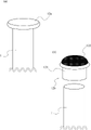
軸部1の下部には、下端に向かうにつれて鋭利になるように形成されている突端部11が設けられており、軸部1の上端には、軸部1の中心部の断面に比べて直径が大きい円盤状の上端部12aが設けられている。
なお、軸部1は、中実の金属部材によって構成されていることが好ましいが、径が大きい場合は中空状に構成されていてもよい。
A
The
突端部11は、支持具Xを地面に貫入できる程度に鋭利に形成されており、軸部1と一体となって設けられている。
なお、図1における突端部11は、軸部1の中心へ向かうように鋭利になっているが、軸部1の側面部に向かうように鋭利になっていてもよい。前者の場合は支持具を地面に垂直に打ち込みやすくなり、後者の場合は突端部11の先端をより鋭利に形成することができるため、固い地面にも打ち込みやすくなる。
The
1 is sharpened toward the center of the
また、図2(a)に示すように、上端部12aは、軸部1と一体となって形成されているが、別途溶接によって取り付けられてもよい。また、上端部12aの上面は、軸部1の軸方向に対して水平であることが好ましい。
上端部12aによって、打ち込む際に叩きつけることのできる面が大きくなるため、支持具Xを地面に打ち込みやすくなる。
なお、上端部12aは、なくともよく、ただ単に軸部1の上端があってもよい。
Further, as shown in FIG. 2(a), the
Since the
The
また、図2(b)に示すように軸部1の上端にキャップ12bを取り付けていてもよい。
キャップ12bは、軸部1の最上端に篏合して取り付け可能な部品であって、キャップ本体121と、弾性部材122と、によって構成されている。
A
The
キャップ本体121は、内部が空洞状に構成されており、ここにおいて軸部1と篏合して取り付けられる。
なお、軸部1が中空状である場合は、キャップ本体121は突形状となり、ねじ込むようにして軸部1に取り付けられる。
The cap
When the
弾性部材122は、キャップ本体121の上面に固定されて取り付けられる、弾性をもつ部材であって、支持具Xを地面に打ち込む際の支持具Xからの反発を抑える効果をもつ。これによって、支持具Xに与える力積を下方に向けて効率よくかけることができるようになり、支持具Xの打ち込み作業が簡便になる。
なお、弾性部材122は、キャップ12bを取り付けた際に、軸部1の軸方向と水平に設けられることが好ましく、これによって支持具Xを地面に垂直に貫入させやすくできる。
The
The
図1に示すように、支持部2は、略円盤状の部材であって、軸部1の軸方向に対して略垂直に溶接されて固定されており、軸方向に対して略平行に設けられた穿孔部Hと、穿孔部Hが含まれる面に対して略垂直に設けられる切込み部Cと、を有する。
As shown in FIG. 1, the
また、本実施形態において支持部2は、軸部1が伸びる方向に沿って二つ設けられている。これによって、支持部2にそれぞれ設けられる穿孔部Hが同一直線状に位置するようになる。
なお、支持部2は3つ以上設けられていてもよく、軸部に垂直な異なる方向に向けて複数設けられていてもよい。
In addition, in this embodiment, two
Three or more supporting
穿孔部Hは、支持部2の中心部から円形状に設けられる穴であって、後述する棒状部材F2を挿入した状態で支持する。
また、穿孔部Hによって形成される支持部2の内周面には、軸部1と平行となるように面取り加工がなされている。
The perforated portion H is a hole formed in a circular shape from the center of the
Further, the inner peripheral surface of the
なお、穿孔部Hを形成する方法は、支持部2を穿孔することに限られず、支持部2の曲げ加工によって形成しても、鋳造によって形成していてもよい。
The method of forming the perforated portion H is not limited to perforating the
切込み部Cは、支持部2における軸部1との接続点の対称位置から穿孔部Hにかけて設けられる切れ込みであって、後述する線材Rを挿入することができる幅を持つ。
なお、切込み部Cの幅は、棒状部材F2が脱落しないために棒状部材F2の外径よりも狭く構成されていることが好ましい。
The notch portion C is a notch provided from the symmetrical position of the connection point with the
The width of the cut portion C is preferably narrower than the outer diameter of the rod-shaped member F2 so that the rod-shaped member F2 does not come off.
なお、支持部2は弾性をもつ部材によって形成してもよく、この場合、棒状部材F2を切込み部Cへ押し込むことで篏合することができる。
The supporting
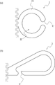
図3(a)は、本実施形態における支持部2の上面図を示す。なお、本図においては軸部1と支持部2の接続点は省略している。
FIG. 3(a) shows a top view of the
図3(a)に示すように、切込み部Cは、穿孔部Hから支持部2の外側に向かって、幅広となるように構成されている。このように構成することによって、線材Rの穿孔部Hへの挿入を容易にするとともに、支持部2からの脱落を起こりにくくすることができる。
As shown in FIG. 3( a ), the cut portion C is configured to become wider from the perforated portion H toward the outside of the
なお、支持部2からの線材Rの脱落を防ぐために、切込み部Cの位置は、図3(b)に記載のように、軸部1と支持部2との接続点の付近に設けていることがこのましい。このように構成にすることによって、線材Rを引掛けるように穿孔部Hに挿入させ、線材Rを支持具Xから離す向きに引張しても切込み部Cから脱落しにくくすることができる。
In addition, in order to prevent the wire R from falling off from the
さらに好ましくは、切込み部Cの両側にある支持部2の端部のうち一端に、切込み部Cを閉塞するフック部材を設けていてもよい。
上記フック部材は、穿孔部Hに向けて押し込み可能であり、押し込む力がかからないときは、弾性作用によって切込み部Cを閉塞する位置に戻るように設けられている。
これによって、所謂カラビナのようにして、線材Rを簡便に穿孔部Hに挿入し、さらに脱落を阻止することができるようになる。
More preferably, one of the ends of the
The hook member can be pushed toward the perforated portion H, and is provided so as to return to a position closing the cut portion C by an elastic action when the pushing force is not applied.
This makes it possible to easily insert the wire rod R into the perforated portion H like a so-called carabiner and prevent it from falling out.
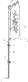
図4は、支持具Xが地面に打ち込まれ、さらにのぼり旗Fが設置された状態を表す斜視図である。 FIG. 4 is a perspective view showing a state in which the support X is driven into the ground and the flag F is installed.
図4に示すように、のぼり旗Fは、情報を表示する薄布部材である表示部F1と、表示部F1を側面から支持する棒状部材F2と、表示部F1を上方から吊り下げる吊るし部F3と、から成る。 As shown in FIG. 4, the banner F includes a display portion F1 which is a thin cloth member for displaying information, a rod-shaped member F2 which supports the display portion F1 from the side, and a suspension portion F3 which suspends the display portion F1 from above. and consists of
棒状部材F2は、プラスチック製の長尺の旗竿であって、複数の中空材が組み合わさり任意の位置関係で固定可能であることによって、軸方向の長さが変更可能であるように構成されている。これにより、支持具Xの打ち込み深さに合わせて棒状部材F2の長さを調整することができる。 The rod-shaped member F2 is an elongated flag pole made of plastic, and is configured such that the length in the axial direction can be changed by combining a plurality of hollow members so that they can be fixed in an arbitrary positional relationship. there is Thereby, the length of the rod-shaped member F2 can be adjusted according to the driving depth of the support X. As shown in FIG.
また、棒状部材F2は、支持具Xに設けられる2つの支持部2に同時に挿入されることによって、軸部1が地面に打ち込まれる向きと略同一方向に立設される。
これにより、のぼり旗Fを、支持具Xに沿わせた状態で支持することができる。
Further, the rod-shaped member F2 is inserted into the two
As a result, the banner F can be supported along the support X.
なお、穿孔部Hと棒状部材F2の周形状を略同一にすることによって、棒状部材F2を支持部2に篏合して固定し、支持部2に対して動きにくくすることができる。
In addition, by making the perforated portion H and the rod-like member F2 have substantially the same circumferential shape, the rod-like member F2 can be fitted and fixed to the
さらに、穿孔部Hと棒状部材F2の断面形状を楕円形状や角形状にすることによれば、棒状部材F2の回転を抑え、表示部F1を常に任意の方向に向けることができるようになる。 Furthermore, by making the cross-sectional shape of the perforated portion H and the rod-shaped member F2 elliptical or square, the rotation of the rod-shaped member F2 is suppressed, and the display portion F1 can always be oriented in an arbitrary direction.
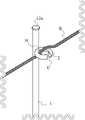
図5は、支持部2に線材Rが支持されている様子を表す模式図を表している。
FIG. 5 is a schematic diagram showing how the wire R is supported by the supporting
図5に示すように、線材Rは支持部2の下方から穿孔部Hに通じ、穿孔部Hから支持部2の上方に覆いかぶさるように当接されて支持部2に支持される。
As shown in FIG. 5, the wire rod R extends from below the supporting
なお、線材Rには、ワイヤー、ロープ(特にトラロープ等の目立ちやすいもの)、PEテープ等の帯状のものが挙げられ、それらの部材の最小幅は切込み部Cの幅よりも小さいことが好ましい。 The wire R may be a wire, a rope (especially conspicuous one such as a tiger rope), or a strip such as a PE tape, and the minimum width of these members is preferably smaller than the width of the cut portion C.
また、切込み部Cが、穿孔部Hが含まれる面に対して略垂直に設けられていることによって、上記のように支持された線材Rが切込み部Cから脱落しにくくなる。 In addition, since the cut portion C is provided substantially perpendicular to the plane including the perforated portion H, the wire rod R supported as described above is less likely to drop out of the cut portion C.
図6は、支持具Xに、のぼり旗Fと、線材Rとが同時に支持される様子を表す斜視図である。 FIG. 6 is a perspective view showing how the banner F and the wire rod R are simultaneously supported by the support X. As shown in FIG.
図6に示すように、穿孔部Hは、線材Rが挿入されている状態で、さらに棒状部材F2を挿入可能な大きさに形成されている。 As shown in FIG. 6, the perforated portion H is sized so that the rod-like member F2 can be inserted while the wire rod R is inserted.
以下、図面を用いて、本発明の使用方法について記載する。本発明は、境界を形成する目的をもつ使用者によって用いられる。
なお、使用の態様は以下の記載に限られず、その順番は前後してもよい。
The method of using the present invention will be described below with reference to the drawings. The present invention is used by users with the goal of creating boundaries.
In addition, the mode of use is not limited to the description below, and the order thereof may be changed.
まず、使用者は、軸部1の突端部11を地面に突き立てた状態で上端部12aをハンマー等で殴打することで、支持具Xを地面に打ち込む。使用者は上記作業を複数の支持具Xについて適当な間隔をもって行う。
First, the user hits the
次に、使用者は、図5に示すように、線材Rの一部を切込み部Cに沿わせ、そのまま穿孔部Hに挿入する。
これを複数の支持具Xそれぞれに行う。
Next, as shown in FIG. 5, the user places a part of the wire rod R along the notch C and inserts it into the hole H as it is.
This is performed for each of the plurality of supports X.
次に、使用者は、図4に示すように、棒状部材F2を2つの支持部2に同時に挿入する。
これを複数の支持具Xそれぞれに行う。
Next, the user inserts the rod-like members F2 into the two
This is performed for each of the plurality of supports X.
最後に、使用者は、図6に示すように、線材Rを適当な力で引張し、線材Rを張り、線材Rの端部を軸部1に結び付ける。
上記操作によって、使用者は支持具Xによって境界を形成することができる。
Finally, as shown in FIG. 6, the user pulls the wire R with an appropriate force to tension the wire R and tie the end of the wire R to the
By the operation described above, the user can form a boundary with the support X.
また、使用者は上記と逆の操作を行うことによって支持具Xを回収することができる。 Also, the user can recover the support X by performing the reverse operation.
また、棒状部材F2を線材Rの後に挿入することによって、切込み部Cを棒状部材F2によって塞ぎ、線材Rの脱落を防ぐことができる。 Further, by inserting the rod-shaped member F2 behind the wire R, the cut portion C is closed by the rod-shaped member F2, and the wire R can be prevented from falling off.
また、境界に内側と外側がある場合、切込み部Cが境界の外側を向くように支持具Xを設けることが好ましい。これにより、切込み部Cの方向に押圧する力が働きにくくなるため、挿入された線材Rが脱落しにくくなる。特に境界の角となる部分は、このように構成することが望ましい。 Moreover, if the boundary has an inner side and an outer side, it is preferable to provide the support X so that the cut portion C faces the outer side of the boundary. As a result, a pressing force in the direction of the notch C is less likely to act, so that the inserted wire R is less likely to fall off. In particular, it is desirable to configure the corners of the boundary in this way.
上記構成によって、ロープ等の線材R及びのぼり旗等の棒状部材F2を簡便に取り外し可能とする支持具Xを提供することができる。 With the above configuration, it is possible to provide the support X from which the wire R such as a rope and the rod-like member F2 such as a banner can be easily removed.
≪第二の実施形態≫
以下、図7を用いて本願発明の第二の実施形態に係る支持具Xについて説明を行う。なお、本実施形態において、第一の実施形態と同様の構成と使用方法については、説明を省略する。
<<Second embodiment>>
A support X according to a second embodiment of the present invention will be described below with reference to FIG. In addition, in this embodiment, description of the same configuration and method of use as in the first embodiment is omitted.
図7に示すように、本発明の第二の実施形態に係る支持具Xは、軸部1と、円環支持部2Xと、によって構成されている。
As shown in FIG. 7, a support X according to a second embodiment of the present invention is composed of a
円環支持部2Xは、円環状の支持部本体21と、軸部1と支持部本体21とを接続する略円柱状の接合部22によって構成されている。
The
支持部本体21は、中央に穿孔部Hが設けられており、穿孔部Hは棒状部材F2及び線材Rが挿通可能となるように形成されている。本実施形態においては、切込み部Cがないため、切込み部Cから線材が脱落するおそれはない。
なお、線材Rは穿孔部Hの下面から上面に挿通することで支持部本体21の上面に当接させて支持される。
The supporting portion
The wire R is inserted through the hole H from the lower surface to the upper surface, and is supported by being brought into contact with the upper surface of the supporting portion
接合部22は、軸部1に溶接によって固定されており、軸部1と支持部本体21との間に間隔を設ける。これにより、支持具Xを束にして収納する際に支持部本体21同士が干渉するのを防止できる。
The
また、接合部22は、線材Rを巻き付けることもできるため、線材Rの端部の固定を簡便にすることができる。
Further, since the wire rod R can be wound around the
≪第三の実施形態≫
以下、図8を用いて本願発明の第三の実施形態に係る支持具Xについて説明を行う。なお、本実施形態において、第一の実施形態又は第二の実施形態と同様の構成と使用方法については、説明を省略する。
<<Third Embodiment>>
A support X according to a third embodiment of the present invention will be described below with reference to FIG. In addition, in this embodiment, description of the same configuration and method of use as in the first embodiment or the second embodiment will be omitted.
図8に示すように、本発明の第三の実施形態に係る支持具Xは、軸部1と、締込支持部2Yによって構成されている。
As shown in FIG. 8, a support X according to a third embodiment of the present invention is composed of a
締込支持部2Yは、棒状部材F2や線材Rを支持する締込支持部本体23と、締込支持部本体23と接合し軸部1に篏合する篏合部24と、篏合部24から突設して設けられる対向する2枚の板材である締込部25と、によって構成されている。
The tightening
締込支持部本体23は、第一の実施形態の支持部2と略同一の構造であるが、上面に線材Rが篏合する凹部23aを有する。これによって、隣り合う支持具Xの高さが多少異なっていても線材Rを安定して当接支持することができる。
なお、凹部23aは、締込支持部本体23の付近に設けられることが好ましく、また複数設けられていてもよい。
The tightening support portion
In addition, it is preferable that the
篏合部24は、軸部1の外径と略同一径の内径を持ち、上端から下端に向かう裂け目を有する中空状部材である。これにより、篏合部24を摺動させることで、締込支持部2Yは軸部1上を自在に上下させることができる。
The
締込部25は、上記裂け目の両側の縁から並行に突設された二枚の板材であって、ボルトBを貫入可能な穴がそれぞれの締込部25の略同一位置に設けられている。
The tightening
第三の実施形態に係る支持具Xを使用する際、使用者は、締込支持部2Yを上下に摺動させることで軸部1の適当な位置へ移動させる。
When using the support X according to the third embodiment, the user slides the tightening
次に、使用者は、締込部25にボルトを貫入し、ナットを用いることで篏合部24の裂け目の間隔を狭め、締込支持部2Yを軸部1の適当な位置に固定する。
これにより、のぼり旗Fや線材Rを支持するための適切な高さを調整することができる。
Next, the user inserts a bolt into the tightening
Thereby, an appropriate height for supporting the banner F and the wire rod R can be adjusted.
≪第四の実施形態≫
以下、図9を用いて本願発明の第四の実施形態に係る支持具Xについて説明を行う。なお、本実施形態において、第一~第三の実施形態と同様の構成と使用方法については、説明を省略する。
<<Fourth Embodiment>>
A support X according to a fourth embodiment of the present invention will be described below with reference to FIG. Incidentally, in this embodiment, the description of the same configuration and method of use as those of the first to third embodiments will be omitted.
図9(a)および図9(b)は、第一の実施形態における支持部2の部分に当たる、分離支持部2Zの拡大図を示している。
分離支持部2Zには、軸部1と平行に設けられた穿孔である平行穿孔部H1と、平行穿孔部H1が形成する面に対して垂直に設けられた穿孔である垂直穿孔部H2が形成されている。
FIGS. 9(a) and 9(b) show enlarged views of the
The
平行穿孔部H1と、垂直穿孔部H2とは図9(a)のように結合した状態になっていてもよく、また、図9(b)のようにそれぞれが分離していてもよい。 The parallel perforated portion H1 and the vertical perforated portion H2 may be connected as shown in FIG. 9(a), or may be separated as shown in FIG. 9(b).
平行穿孔部H1は、軸部1に近い側に設けられており、棒状部材F2を挿入可能に設けられている。棒状部材F2が軸部1に近いと、モーメント力が軸部に働きにくくなり、支持具Xにより安定して立設することができる。
The parallel bore portion H1 is provided on the side closer to the
垂直穿孔部H2は、線材Rを挿入可能に設けられている。また、図9(a)に示すように、切込み部Cが上側に向けて設けられており、これによって線材Rを挿入しやすく、かつ脱落しにくくすることができる。 The vertical hole H2 is provided so that the wire rod R can be inserted. Further, as shown in FIG. 9(a), the notch C is provided facing upward, thereby making it easy to insert the wire R and making it difficult for it to come off.
上記のように、棒状部材F2を挿入する部位と、線材Rを挿入する部位と、を別々に設けることによって、それぞれの部材をスムーズに挿入することができるようになる。 By separately providing the portion into which the rod-like member F2 is inserted and the portion into which the wire rod R is inserted, as described above, each member can be smoothly inserted.
また、平行穿孔部H1と、垂直穿孔部H2と、の位置関係はこれに限られず、軸部1に近い側に垂直穿孔部H2が設けられていてもよい。
Further, the positional relationship between the parallel perforated portion H1 and the vertical perforated portion H2 is not limited to this, and the vertical perforated portion H2 may be provided on the side closer to the
上記軸部1や棒状部材F2は、円柱状に記載されているが、角柱であっても、錐体であってもよいが、穿孔部Hの形状と棒状部材F2の断面形状は略同一であることが好ましい。
Although the
1 軸部
11 突端部
12a 上端部
12b キャップ
121 キャップ本体
122 弾性部材
2 支持部
21 支持部本体
22 接合部
23 締込支持部本体
24 篏合部
25 締込部
X 支持具
H 穿孔部
H1 平行穿孔部
H2 垂直穿孔部
C 切込み部
R 線材
F のぼり旗
F1 表示部
F2 棒状部材
F3 吊るし部
B ボルト
1
Claims (7)
前記支持部は、前記軸部の軸方向に対して略平行に穿孔されている穿孔部を有し、
前記穿孔部は、棒状部材または線材の少なくとも何れか一方を挿入した状態で支持する支持具。 comprising an elongated shaft portion and a support portion projecting substantially perpendicularly to the axial direction of the shaft portion;
The support portion has a perforated portion that is perforated substantially parallel to the axial direction of the shaft portion,
The perforated portion is a support that supports at least one of a rod-shaped member and a wire rod inserted therein.
Priority Applications (1)
| Application Number | Priority Date | Filing Date | Title |
|---|---|---|---|
| JP2021021189A JP7338834B2 (en) | 2021-02-12 | 2021-02-12 | support |
Applications Claiming Priority (1)
| Application Number | Priority Date | Filing Date | Title |
|---|---|---|---|
| JP2021021189A JP7338834B2 (en) | 2021-02-12 | 2021-02-12 | support |
Publications (2)
| Publication Number | Publication Date |
|---|---|
| JP2022123701A true JP2022123701A (en) | 2022-08-24 |
| JP7338834B2 JP7338834B2 (en) | 2023-09-05 |
Family
ID=82940441
Family Applications (1)
| Application Number | Title | Priority Date | Filing Date |
|---|---|---|---|
| JP2021021189A Active JP7338834B2 (en) | 2021-02-12 | 2021-02-12 | support |
Country Status (1)
| Country | Link |
|---|---|
| JP (1) | JP7338834B2 (en) |
Citations (6)
| Publication number | Priority date | Publication date | Assignee | Title |
|---|---|---|---|---|
| JPS49141787U (en) * | 1973-04-09 | 1974-12-06 | ||
| JPS58141290U (en) * | 1982-03-17 | 1983-09-22 | 宣真工業株式会社 | Bunting attachment device on flag pole |
| JPS6234062U (en) * | 1985-08-16 | 1987-02-28 | ||
| JPS63101060U (en) * | 1986-12-22 | 1988-06-30 | ||
| JPH0514611U (en) * | 1991-08-08 | 1993-02-26 | 帝金株式会社 | Fence pole mount |
| JPH0543194U (en) * | 1991-10-31 | 1993-06-11 | 株式会社トキワ | Flag tower |
-
2021
- 2021-02-12 JP JP2021021189A patent/JP7338834B2/en active Active
Patent Citations (6)
| Publication number | Priority date | Publication date | Assignee | Title |
|---|---|---|---|---|
| JPS49141787U (en) * | 1973-04-09 | 1974-12-06 | ||
| JPS58141290U (en) * | 1982-03-17 | 1983-09-22 | 宣真工業株式会社 | Bunting attachment device on flag pole |
| JPS6234062U (en) * | 1985-08-16 | 1987-02-28 | ||
| JPS63101060U (en) * | 1986-12-22 | 1988-06-30 | ||
| JPH0514611U (en) * | 1991-08-08 | 1993-02-26 | 帝金株式会社 | Fence pole mount |
| JPH0543194U (en) * | 1991-10-31 | 1993-06-11 | 株式会社トキワ | Flag tower |
Also Published As
| Publication number | Publication date |
|---|---|
| JP7338834B2 (en) | 2023-09-05 |
Similar Documents
| Publication | Publication Date | Title |
|---|---|---|
| US6991413B2 (en) | Drive anchor | |
| AU2013302224B2 (en) | Post, fence, and method and apparatus for installing a post or fence | |
| JP2009019448A (en) | Steel pipe pile tip extension structure and steel pipe pile tip extension construction method | |
| KR101091585B1 (en) | Pile holding device for pile and construction method | |
| JP7338834B2 (en) | support | |
| JP6385866B2 (en) | Chisel hammer for pile removal | |
| JP2010106494A (en) | Foundation pile for erecting post, and post erecting method using the same | |
| US9273441B2 (en) | Tree nail | |
| JP6446515B1 (en) | Underground anchor | |
| JP2017227049A (en) | Pulling out method for embedded pile and apparatus thereof | |
| KR102299598B1 (en) | Multi-suprrort underground anchor for rock | |
| US7325344B2 (en) | Ground-mounted impact insertion and extraction apparatus | |
| JP2014084603A (en) | Pile and pile unit | |
| JP6411130B2 (en) | Driven pile | |
| KR101533938B1 (en) | A bracket support with punching tube for insulating material | |
| JP6607476B1 (en) | Tightening device | |
| JP2008255634A (en) | Dwelling sheath tube | |
| CN205242394U (en) | Repeatedly usable's tubular pile stake point | |
| JP4633697B2 (en) | Steel pipe pile cap and steel pipe pile and footing joint structure | |
| JP5974571B2 (en) | Stabilizing jig for slant pile | |
| JP6016310B2 (en) | Earth anchor | |
| JP3113392U (en) | Pile with anchor pin | |
| JP4649488B2 (en) | Standing aid for flagpole | |
| JPH11293673A (en) | Manually operated pile driving apparatus | |
| JP4456041B2 (en) | Anchor facility for civil engineering facilities |
Legal Events
| Date | Code | Title | Description |
|---|---|---|---|
| A621 | Written request for application examination |
Free format text: JAPANESE INTERMEDIATE CODE: A621 Effective date: 20220413 |
|
| A977 | Report on retrieval |
Free format text: JAPANESE INTERMEDIATE CODE: A971007 Effective date: 20230111 |
|
| A131 | Notification of reasons for refusal |
Free format text: JAPANESE INTERMEDIATE CODE: A131 Effective date: 20230117 |
|
| A521 | Request for written amendment filed |
Free format text: JAPANESE INTERMEDIATE CODE: A523 Effective date: 20230208 |
|
| A131 | Notification of reasons for refusal |
Free format text: JAPANESE INTERMEDIATE CODE: A131 Effective date: 20230523 |
|
| A521 | Request for written amendment filed |
Free format text: JAPANESE INTERMEDIATE CODE: A523 Effective date: 20230719 |
|
| TRDD | Decision of grant or rejection written | ||
| A01 | Written decision to grant a patent or to grant a registration (utility model) |
Free format text: JAPANESE INTERMEDIATE CODE: A01 Effective date: 20230808 |
|
| A61 | First payment of annual fees (during grant procedure) |
Free format text: JAPANESE INTERMEDIATE CODE: A61 Effective date: 20230814 |
|
| R150 | Certificate of patent or registration of utility model |
Ref document number: 7338834 Country of ref document: JP Free format text: JAPANESE INTERMEDIATE CODE: R150 |