JP2022166364A - Control device and control method - Google Patents
Control device and control method Download PDFInfo
- Publication number
- JP2022166364A JP2022166364A JP2021071521A JP2021071521A JP2022166364A JP 2022166364 A JP2022166364 A JP 2022166364A JP 2021071521 A JP2021071521 A JP 2021071521A JP 2021071521 A JP2021071521 A JP 2021071521A JP 2022166364 A JP2022166364 A JP 2022166364A
- Authority
- JP
- Japan
- Prior art keywords
- cooling
- showcase
- unit
- time
- grace
- Prior art date
- Legal status (The legal status is an assumption and is not a legal conclusion. Google has not performed a legal analysis and makes no representation as to the accuracy of the status listed.)
- Pending
Links
Images



Landscapes
- Devices That Are Associated With Refrigeration Equipment (AREA)
- Remote Monitoring And Control Of Power-Distribution Networks (AREA)
- Supply And Distribution Of Alternating Current (AREA)
Abstract
【課題】店舗の一部の電力を賄うことが可能な非常用発電機を用いた場合でも、店舗に設けられたショーケースの庫内温度を維持可能とする。【解決手段】庫内温度を監視する監視部301と、庫内温度の上昇率及び監視部301による監視結果に基づいて、庫内温度が上限値に達するまでの猶予時間を推定する猶予時間推定部305と、非常用発電機の供給可能電力、冷却運転に必要な消費電力及び猶予時間推定部305による推定結果に基づいて、冷却対象とするショーケース1を選択する冷却対象選択部306と、猶予時間推定部305による推定結果に基づいて、冷却対象として選択されたショーケース1に対する冷却時間を設定する冷却時間設定部307と、冷却対象として選択されたショーケースに対し、冷却時間だけ冷却を行うよう指示する冷却制御部308とを備え、猶予時間推定部305は、冷却対象として選択されたショーケース1による冷却運転が停止した場合、猶予時間の推定を再度行う。【選択図】図2An object of the present invention is to maintain the internal temperature of a showcase provided in a store even when using an emergency power generator capable of supplying power for part of the store. A monitoring unit 301 for monitoring the temperature inside the refrigerator, and a grace time estimation for estimating the grace time until the temperature inside the refrigerator reaches an upper limit value based on the rate of increase of the temperature inside the refrigerator and the result of monitoring by the monitoring unit 301. a cooling target selection unit 306 that selects the showcase 1 to be cooled based on the suppliable power of the emergency power generator, the power consumption required for the cooling operation, and the estimation result of the grace time estimation unit 305; A cooling time setting unit 307 that sets the cooling time for the showcase 1 selected as the cooling target based on the estimation result by the grace time estimating unit 305, and cools the showcase selected as the cooling target for the cooling time. A grace time estimating unit 305 re-estimates the grace time when the cooling operation of the showcase 1 selected as the object to be cooled stops. [Selection drawing] Fig. 2
Description
本開示は、ショーケースを制御する制御装置及び制御方法に関する。 The present disclosure relates to a control device and control method for controlling showcases.
従来、スーパーマーケット等の店舗に設けられたショーケースに対し、庫内品質に余裕のないショーケースを省エネ制御の対象から除外した上で、省エネ制御を行うデマンド制御装置が知られている(例えば特許文献1参照)。このデマンド制御装置では、ショーケースに対して庫内品質を維持しつつ店舗全体での省エネが可能となる。 Conventionally, demand control devices are known that perform energy-saving control after excluding showcases with insufficient internal quality from the targets of energy-saving control for showcases installed in stores such as supermarkets (for example, patent Reference 1). With this demand control device, it is possible to save energy in the entire store while maintaining the quality inside the showcase.
一方、近年、異常気象又は地震等の災害により、大規模な停電が発生する事象が増加している。そのため、スーパーマーケット等の店舗において、停電に対する備えを行うことは重要となっている。
停電に備える方法としては、非常用発電機を用いる方法が挙げられる。非常用発電機としては、店舗全体の電力を賄うことが可能な発電機を用いることはコスト面で困難な場合があり、店舗の一部の電力を賄うことが可能な発電機が用いられる場合が多い。
On the other hand, in recent years, there have been an increasing number of events in which large-scale blackouts occur due to disasters such as abnormal weather or earthquakes. Therefore, it is important for stores such as supermarkets to prepare for power outages.
As a method of preparing for a power outage, there is a method of using an emergency power generator. As an emergency generator, it may be difficult in terms of cost to use a generator that can cover the power of the entire store. There are many.
しかしながら、従来のデマンド制御装置において、店舗の一部の電力を賄うことが可能な非常用発電機を用いて制御を実施しようとした場合、従来のデマンド制御装置では店舗全体の電力を賄うことが可能であることを前提としているため、ショーケースの庫内品質を維持できない場合がある。 However, in the conventional demand control device, if an attempt is made to perform control using an emergency power generator that can cover a portion of the power of the store, the conventional demand control device cannot cover the power of the entire store. Since it is assumed that it is possible, it may not be possible to maintain the quality inside the showcase.
本開示は、上記のような課題を解決するためになされたもので、店舗の一部の電力を賄うことが可能な非常用発電機を用いた場合でも、店舗に設けられたショーケースの庫内温度を維持可能な制御装置を提供することを目的としている。 The present disclosure has been made to solve the above-mentioned problems. An object of the present invention is to provide a control device capable of maintaining the internal temperature.
本開示に係る制御装置は、複数のショーケース毎に、庫内温度を監視する監視部と、ショーケース毎の冷却運転を停止した場合での庫内温度の上昇率及び監視部による監視結果に基づいて、ショーケース毎に、庫内温度が上限値に達するまでの猶予時間を推定する猶予時間推定部と、非常用発電機の供給可能電力、ショーケース毎の冷却運転に必要な消費電力及び猶予時間推定部による推定結果に基づいて、ショーケースの中から、冷却対象とするショーケースを選択する冷却対象選択部と、猶予時間推定部による推定結果に基づいて、冷却対象選択部により冷却対象として選択されたショーケースに対する冷却時間を設定する冷却時間設定部と、冷却対象選択部により冷却対象として選択されたショーケースに対し、冷却時間設定部により設定された冷却時間だけ冷却を行うよう指示する冷却制御部とを備え、猶予時間推定部は、冷却対象選択部により冷却対象として選択されたショーケースによる冷却運転が停止した場合、猶予時間の推定を再度行うことを特徴とする。 The control device according to the present disclosure includes a monitoring unit that monitors the temperature inside the refrigerator for each of a plurality of showcases, and the rate of increase of the temperature inside the refrigerator when the cooling operation of each showcase is stopped and the result of monitoring by the monitoring unit. Based on this, for each showcase, a grace time estimating unit that estimates the grace time until the internal temperature reaches the upper limit value, the power that can be supplied by the emergency generator, the power consumption required for the cooling operation of each showcase, and A cooling object selection unit that selects a showcase to be cooled from among the showcases based on the estimation result of the grace time estimation unit; and a cooling time setting unit for setting the cooling time for the showcase selected as the cooling time setting unit. and the grace time estimating section re-estimates the grace time when the cooling operation of the showcase selected as the cooling target by the cooling target selection section is stopped.
本開示によれば、上記のように構成したので、店舗の一部の電力を賄うことが可能な非常用発電機を用いた場合でも、店舗に設けられたショーケースの庫内温度を維持可能となる。 According to the present disclosure, since it is configured as described above, it is possible to maintain the internal temperature of the showcase provided in the store even when using an emergency generator that can cover part of the power of the store. becomes.
以下、実施の形態について図面を参照しながら詳細に説明する。
実施の形態1.
図1は実施の形態1に係る制御システムの構成例を示す図である。
制御システムは、図1に示すように、複数のショーケース1、電力量計2及び制御装置(上位コントローラ)3を備えている。
Hereinafter, embodiments will be described in detail with reference to the drawings.
FIG. 1 is a diagram showing a configuration example of a control system according to
The control system includes a plurality of
ショーケース1は、店舗に設置されている。なお、ショーケース1としては、例えば、扉の付いているクローズドショーケース及び扉の付いていないオープンショーケースが挙げられる。また、ショーケース1は、庫内の冷却以外に、例えば、照明、防露ヒータによる防露又は除霜ヒータによる除霜といった機能を有している場合がある。また、ショーケース1は、庫内の温度(庫内温度)を示すデータを、制御装置3に送信する。
A
なお、店舗には、非常用発電機が設けられている。非常用発電機は、店舗の一部の電力を賄うことが可能な発電機である。そして、ショーケース1は、停電時のような非常時には、制御装置3による制御に従い、非常用発電機により供給された電力により駆動する。
The store is equipped with an emergency power generator. An emergency power generator is a power generator that can cover part of the store's power. In an emergency such as a power outage, the
電力量計2は、店舗に設置されたショーケース1の消費電力を計測する。電力量計2により計測された消費電力を示すデータは、制御装置3に送信される。
The watt-
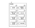
制御装置3は、店舗に設置されたショーケース1を制御する。この制御装置3は、図2に示すように、監視部301、消費電力推定部302、温度上昇率推定部303、切替え部304、猶予時間推定部305、冷却対象選択部306、冷却時間設定部307及び冷却制御部308を備えている。
The
監視部301は、ショーケース1毎に、庫内温度及び消費電力を監視する。この際、監視部301は、各ショーケース1から送信されたデータに基づいて、各ショーケース1の庫内温度の監視を行う。また、監視部301は、電力量計2から送信されたデータに基づいて、各ショーケース1の消費電力の監視を行う。
The
消費電力推定部302は、監視部301による監視結果に基づいて、ショーケース1毎に、冷却運転に必要な消費電力を推定する。
The power
温度上昇率推定部303は、監視部301による監視結果に基づいて、ショーケース1毎に、冷却運転を停止した場合での庫内温度の上昇率を推定する。
The temperature
切替え部304は、ショーケース1が設置された店舗において通常時に使用される電力系統からの電力供給による駆動から、非常用発電機からの電力供給による駆動への切替えを決定する。
The
猶予時間推定部305は、切替え部304により非常用発電機からの電力供給による駆動への切替えが決定された場合、監視部301による監視結果及び温度上昇率推定部303による推定結果に基づいて、ショーケース1毎に、庫内温度が上限値に達するまでの猶予時間を推定する。上限値は、ショーケース1毎に事前に設定される。
また、猶予時間推定部305は、冷却対象選択部306により冷却対象として選択されたショーケース1による冷却運転が停止した場合、猶予時間の推定を再度行う。
When the
Further, when the cooling operation of the
冷却対象選択部306は、非常用発電機の供給可能電力、猶予時間推定部305による推定結果及び消費電力推定部302による推定結果に基づいて、ショーケース1の中から、冷却対象とするショーケース1を選択する。なお、冷却対象選択部306は、非常用発電機の供給可能電力を、例えばユーザ入力により事前に把握可能である。
The cooling
冷却時間設定部307は、猶予時間推定部305による推定結果に基づいて、冷却対象選択部306により冷却対象として選択されたショーケース1に対する冷却時間を設定する。
The cooling
冷却制御部308は、冷却対象選択部306により冷却対象として選択されたショーケース1に対し、冷却時間設定部307により設定された冷却時間又は庫内温度が設定温度に対して閾値以下となるまで、冷却を行うよう指示する。閾値は、庫内温度の設定温度以下の値であり、ショーケース1毎に事前に設定される。
The
なお図2では、消費電力推定部302及び温度上昇率推定部303が、制御装置3の内部に設けられた場合を示した。しかしながら、消費電力推定部302及び温度上昇率推定部303は、制御装置3の外部に設けられていてもよい。この場合、制御装置3は、外部から、ショーケース1毎の冷却運転に必要な消費電力を示すデータ及びショーケース1毎の庫内温度の上昇率を示すデータを取得する。またこの場合には、監視部301による消費電力の監視は不要である。例えば、消費電力推定部302及び温度上昇率推定部303は、ショーケース1に個々に設けられていてもよい。
Note that FIG. 2 shows a case where the
また上記では、冷却制御部308が、冷却対象選択部306により冷却対象として選択されたショーケース1に対し、冷却時間設定部307により設定された冷却時間又は庫内温度が設定温度に対して閾値以下となるまで、冷却を行うよう指示する場合を示した。しかしながら、これに限らず、冷却制御部308が、冷却対象選択部306により冷却対象として選択されたショーケース1に対し、冷却時間設定部307により設定された冷却時間だけ冷却を行うよう指示してもよい。
Further, in the above, the
次に、図1,2に示す実施の形態1に係る制御装置3の動作例について、図3,4を参照しながら説明する。
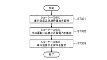
まず、図1,2に示す実施の形態1に係る制御装置3による学習動作例について、図3を参照しながら説明する。なお、ショーケース1は、庫内温度を示すデータを、制御装置3に送信している。また、電力量計2は、ショーケース1毎に計測した消費電力を示すデータを、制御装置3に送信している。
Next, an operation example of the
First, an example of the learning operation by the
図1,2に示す実施の形態1に係る制御装置3による学習動作例では、図3に示すように、まず、監視部301は、ショーケース1毎に、庫内温度及び消費電力を監視する(ステップST301)。この際、監視部301は、各ショーケース1から送信されたデータに基づいて、各ショーケース1の庫内温度の監視を行う。また、監視部301は、電力量計2から送信されたデータに基づいて、各ショーケース1の消費電力の監視を行う。この監視部301による処理は繰り返し実施される。
In the example of the learning operation by the
次いで、消費電力推定部302は、監視部301による監視結果に基づいて、ショーケース1毎に、冷却運転に必要な消費電力を推定する(ステップST302)。
Next, power
ここで、ショーケース1では、冷却以外に、例えば、照明、防露ヒータによる防露又は除霜ヒータによる除霜等の処理で電力が消費される場合がある。そのため、例えば、消費電力推定部302は、冷却のみに電力が消費されていると想定される時間帯(例えば夜間)の消費電力から、冷却運転に必要な消費電力を推定する。
Here, in the
また、温度上昇率推定部303は、監視部301による監視結果に基づいて、ショーケース1毎に、冷却運転を停止した場合での庫内温度の上昇率を推定する(ステップST303)。
Based on the results of monitoring by
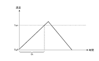
この際、例えば図5に示すように、まず、温度上昇率推定部303は、ショーケース1毎に、通常運転時にサーモオフ(冷却運転を停止)してからサーモオンになる(冷却運転を開始する)までの時間及び温度の変化を計測する。図5において、Toffはサーモオフとなった際での庫内温度を示し、Tonはサーモオンとなった際での庫内温度を示し、tnはサーモオフからサーモオンになるまでの時間を示している。そして、下式(1)に示すように、温度上昇率推定部303は、ショーケース1毎に、サーモオフからサーモオンになるまでの時間とその温度差から、庫内温度の上昇率を算出する。式(1)において、An(n)は温度上昇率推定部303によるn回目の推定での庫内温度の上昇率を示している。
その後、下式(2)に示すように、温度上昇率推定部303は、ショーケース1毎に、直近に算出した複数回の庫内温度の上昇率の移動平均から、最終的な庫内温度の上昇率を算出する。式(2)では直近に算出した3回の庫内温度の上昇率の移動平均を求めた場合を示している。式(2)において、Ascは最終的な庫内温度の上昇率を示している。
An(n)=(Ton-Toff)/tn (1)
Asc=(An(n)+An(n-1)+An(n-2))/3 (2)
At this time, for example, as shown in FIG. 5, the temperature rise
After that, as shown in the following formula (2), the temperature
An(n)=(Ton−Toff)/tn (1)
Asc=(An(n)+An(n-1)+An(n-2))/3 (2)
このように、図1,2に示す実施の形態1に係る制御装置3は、通常運転時に、各ショーケース1の庫内温度及び消費電力を監視し、ショーケース1毎に冷却運転に必要な消費電力及び庫内温度の上昇率を学習する。
In this way, the
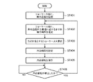
次に、図1,2に示す実施の形態1に係る制御装置3による非常時での制御動作例について、図4を参照しながら説明する。なお、ショーケース1は、庫内温度を示すデータを、制御装置3に送信している。
Next, an example of control operation in an emergency by the
また、切替え部304は、ショーケース1が設置された店舗において通常時に使用される電力系統からの電力供給による駆動から、非常用発電機からの電力供給による駆動への切替えを決定する。例えば、切替え部304は、上記店舗において停電が発生したことを検知した場合又は外部から指示があった場合に、非常用発電機からの電力供給による駆動への切替えを決定する。
Further, the
また、ショーケース1が、庫内の冷却以外の機能(例えば、照明、防露ヒータによる防露又は除霜ヒータによる除霜)を有する場合、切替え部304は、上記切替えの決定とともに、当該ショーケース1に対し、庫内の冷却以外の機能の停止を指示することが望ましい。すなわち、切替え部304は、非常時での制御の前提として、消費電力を少なくするために庫内の冷却以外の機能を停止させ、また、庫内温度の上昇を防ぐためにヒータを停止させることが望ましい。なお、上記の機能の停止は、ショーケース1自身が自発的に行ってもよい。
Further, when the
更に、ショーケース1が扉の付いていないオープンショーケースである場合、作業者によって、当該ショーケース1に対してナイトカバーがされることが望ましい。これにより、停電による店舗内の環境の変化(空調の停止等)による影響を抑制することが可能となる。
Furthermore, if the
図1,2に示す実施の形態1に係る制御装置3による非常時での制御動作例では、図4に示すように、まず、監視部301は、ショーケース1毎に、庫内温度を監視する(ステップST401)。この際、監視部301は、各ショーケース1から送信されたデータに基づいて、各ショーケース1の庫内温度の監視を行う。この監視部301による処理は繰り返し実施される。
In the example of the control operation in an emergency by the
次いで、猶予時間推定部305は、監視部301による監視結果及び温度上昇率推定部303による推定結果に基づいて、ショーケース1毎に、庫内温度が上限値に達するまでの猶予時間を推定する(ステップST402)。
Next, the grace
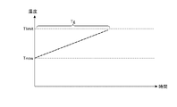
すなわち、例えば図6及び下式(3)に示すように、猶予時間推定部305は、ショーケース1毎に、庫内温度の上限値と現在値との差分値を、庫内温度の上昇率で割ることで、猶予時間を算出する。図6及び式(3)において、Tgは猶予時間を示し、Tlimitは庫内温度の上限値を示し、Tnowは庫内温度の現在値を示している。
Tg=(Tlimit-Tnow)/Asc (3)
That is, for example, as shown in FIG. 6 and the following formula (3), the grace
Tg=(Tlimit−Tnow)/Asc (3)
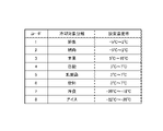
なお、例えば図7に示すように、ショーケース1は、庫内に収容される冷却対象物の分類(冷却対象分類)に応じてコードが設定可能である。また、このコードは、設定温度帯とも紐付いている。そのため、制御装置3は、ショーケース1のコードから当該ショーケース1の設定温度帯を把握可能であり、この設定温度帯からショーケース1の庫内温度に対する上限値を事前に設定可能である。この際、制御装置3は、例えば、設定温度帯の上限に対して所定値(例えば3℃)を加算した値を上限値として設定してもよい。また、商品には保管温度が決められており、制御装置3は、その保管温度に応じて上限値を設定してもよい。
For example, as shown in FIG. 7, codes can be set for the
また、制御装置3は、ショーケース1の庫内温度に対する上限値を設定せず、外部で設定された上限値を示すデータを取得してもよい。例えばショーケース1が庫内温度に対する上限値を設定してもよい。
Alternatively, the
次いで、冷却対象選択部306は、非常用発電機の供給可能電力、猶予時間推定部305による推定結果及び消費電力推定部302による推定結果に基づいて、ショーケース1の中から、冷却対象とするショーケース1を選択する(ステップST403)。
Next, the cooling
この際、例えば、冷却対象選択部306は、猶予時間推定部305により推定された猶予時間の短いショーケース1から順に、冷却対象として選択する。また、冷却対象選択部306は、冷却対象として選択したショーケース1の冷却運転に必要な消費電力の総和を算出する。そして、冷却対象選択部306は、非常用発電機の供給可能電力に対して上記総和が超えないように、冷却対象の選択を繰返す。
At this time, for example, the cooling
なお、例えば、店舗に設置されたショーケース1のうち、非常用発電機からの電力供給による駆動対象又は駆動対象外とするショーケース1を、ユーザが事前に設定することも可能である。この際、ユーザは、上記駆動対象又は駆動対象外とするショーケース1を識別可能な情報又は当該ショーケース1に対応したコードを設定する。この場合、冷却対象選択部306は、ショーケース1のうち、駆動対象であるショーケース1の中から、冷却対象とするショーケース1を選択する。すなわち、冷却対象選択部306は、駆動対象外であるショーケース1については、冷却対象からは除外する。
For example, among the
また、例えば、冷却対象とするショーケース1の優先順位をユーザが事前に設定することも可能である。この場合、冷却対象選択部306は、ユーザにより設定された優先順位を考慮し、例えば猶予時間が少なく且つ優先順位の高いショーケース1から順に、冷却対象として選択する。
Further, for example, the user can set in advance the order of priority of the
次いで、冷却時間設定部307は、猶予時間推定部305による推定結果に基づいて、冷却対象選択部306により冷却対象として選択されたショーケース1に対する冷却時間を設定する(ステップST404)。
Next, cooling
この際、例えば、冷却時間設定部307は、冷却対象外の全てのショーケース1の猶予時間を考慮し、当該猶予時間のうちの最小時間が一定値以下になるまでの時間を、冷却時間として決定する。上記一定値は事前に設定される。
At this time, for example, the cooling
次いで、冷却制御部308は、冷却対象選択部306により冷却対象として選択されたショーケース1に対し、冷却時間設定部307により設定された冷却時間又は庫内温度が閾値以下となるまで、冷却を行うよう指示する(ステップST405)。その後、冷却対象選択部306により冷却対象として選択されたショーケース1は、冷却運転を開始する。
Next, the cooling
その後、制御装置3は、冷却対象選択部306により冷却対象として選択されたショーケース1による冷却運転が停止したかを判定する(ステップST406)。
After that, the
このステップST406において、制御装置3が、冷却対象であるショーケース1の冷却運転が停止していないと判定した場合、シーケンスはステップST405に戻り、待機状態となる。
一方、ステップST406において、制御装置3が、冷却対象であるショーケース1の冷却運転が停止したと判定した場合、シーケンスはステップST402に戻り、猶予時間推定部305は猶予時間の推定を再度行う。
In this step ST406, when the
On the other hand, in step ST406, when the
次に、図1,2に示す実施の形態1に係る制御装置3による制御動作の具体例について、図8~11を参照しながら説明する。なお以下では、非常用発電機の供給可能電力は1500Wである。また、制御対象が制御対象とするショーケース1は4台(第1のショーケース1~第4のショーケース1)である。第1のショーケース1の冷却運転に必要な消費電力は400Wである。また、第2のショーケース1の冷却運転に必要な消費電力は600Wである。また、第3のショーケース1の冷却運転に必要な消費電力は1200Wである。また、第4のショーケース1の冷却運転に必要な消費電力は800Wである。また、冷却時間は、冷却対象外の全てのショーケース1の猶予時間のうちの最小時間-1分である。また、冷却対象とするショーケース1に対して優先順位は付けられていない。
Next, specific examples of control operations by the
まず、制御装置3は、非常用発電機からの電力供給による駆動への切替えを決定すると、ショーケース1毎に庫内温度が上限値に達するまでの猶予時間を推定し、冷却対象とするショーケース1を選択する。
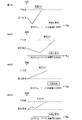
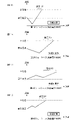
図8では、第1のショーケース1の猶予時間が2分であり、第2のショーケース1の猶予時間が5分であり、第3のショーケース1の猶予時間が10分であり、第4のショーケース1の猶予時間が8分である。この場合、まず、制御装置3は、猶予時間が最も短い第1のショーケース1を冷却対象として選択する。この場合、第1のショーケース1の冷却運転に必要な消費電力は400Wであるため、非常用発電機により供給可能な残りの電力は、1100W(=1500W-400W)となる。そして、制御装置3は、猶予時間が次に短い第2のショーケース1を冷却対象として選択する。この場合、第2のショーケース1の冷却運転に必要な消費電力は600Wであるため、非常用発電機により供給可能な残りの電力は、500W(=1100W-600W)となる。そして、制御装置3は、非常用発電機により供給可能な残りの電力で冷却運転が可能なショーケース1は残っていないため、冷却対象とするショーケース1の選択を終了する。
First, when the
In FIG. 8, the grace time of the
次に、制御装置3は、各ショーケース1の猶予時間に基づいて、冷却対象として選択したショーケース1の冷却時間を設定する。
図8では、冷却対象外の全てのショーケース1の猶予時間のうちの最小時間は、第4のショーケース1の猶予時間(8分)である。そのため、制御装置3は、7分(=8分-1分)を冷却時間として設定する。
Next, the
In FIG. 8, the minimum time of the grace times of all the
次に、制御装置3は、第1のショーケース1及び第2のショーケース1に対し、7分間又は庫内温度が閾値以下となるまで、冷却を行うよう指示する。そして、第1のショーケース1及び第2のショーケース1は冷却運転を開始する。一方、第3のショーケース1及び第4のショーケース1は停止状態となる。
Next, the
そして、この例では、3分後に、第1のショーケース1が、設定温度に対して十分冷えた(庫内温度が閾値以下となった)ため冷却運転を停止する。
In this example, after 3 minutes, the cooling operation is stopped because the
この場合、制御装置3は、ショーケース1毎に庫内温度が上限値に達するまでの猶予時間を再度推定し、冷却対象とするショーケース1を選択する。
図9では、第1のショーケース1の猶予時間が5分であり、第2のショーケース1の猶予時間が7分であり、第3のショーケース1の猶予時間が7分であり、第4のショーケース1の猶予時間が5分である。なお、第1のショーケース1は、設定温度に対して十分冷えた状態であるため、冷却対象からは除外するものとする。この場合、まず、制御装置3は、猶予時間が最も短い第4のショーケース1を冷却対象として選択する。この場合、第4のショーケース1の冷却運転に必要な消費電力は800Wであるため、非常用発電機により供給可能な残りの電力は、700W(=1500W-800W)となる。そして、制御装置3は、猶予時間が次に短い第2のショーケース1を冷却対象として選択する。なお、第3のショーケース1の猶予時間も第2のショーケース1の猶予時間と同じであるが、消費電力を考慮して、第2のショーケース1を優先するものとする。この場合、第2のショーケース1の冷却運転に必要な消費電力は600Wであるため、非常用発電機により供給可能な残りの電力は、100W(=700W-600W)となる。そして、制御装置3は、非常用発電機により供給可能な残りの電力で冷却運転が可能なショーケース1は残っていないため、冷却対象とするショーケース1の選択を終了する。
In this case, the
In FIG. 9, the grace period of the
次に、制御装置3は、各ショーケース1の猶予時間に基づいて、冷却対象として選択したショーケース1の冷却時間を設定する。
図9では、冷却対象外の全てのショーケース1の猶予時間のうちの最小時間は、第1のショーケース1の猶予時間(5分)である。そのため、制御装置3は、4分(=5分-1分)を冷却時間として設定する。
Next, the
In FIG. 9, the minimum grace period of all the
次に、制御装置3は、第2のショーケース1及び第4のショーケース1に対し、4分間又は庫内温度が閾値以下となるまで、冷却を行うよう指示する。そして、第2のショーケース1及び第4のショーケース1は冷却運転を開始する。一方、第1のショーケース1及び第3のショーケース1は停止状態となる。
Next, the
そして、この例では、2分後に、第2のショーケース1が、設定温度に対して十分冷えた(庫内温度が閾値以下となった)ため冷却運転を停止する。
In this example, after 2 minutes, the
この場合、制御装置3は、ショーケース1毎に庫内温度が上限値に達するまでの猶予時間を再度推定し、冷却対象とするショーケース1を選択する。
図10では、第1のショーケース1の猶予時間が3分であり、第2のショーケース1の猶予時間が9分であり、第3のショーケース1の猶予時間が5分であり、第4のショーケース1の猶予時間が7分である。なお、第1のショーケース1及び第2のショーケース1は、設定温度に対して十分冷えた状態であるため、冷却対象からは除外するものとする。この場合、まず、制御装置3は、猶予時間が最も短い第3のショーケース1を冷却対象として選択する。この場合、第3のショーケース1の冷却運転に必要な消費電力は1200Wであるため、非常用発電機により供給可能な残りの電力は、300W(=1500W-1200W)となる。そして、制御装置3は、非常用発電機により供給可能な残りの電力で冷却運転が可能なショーケース1は残っていないため、冷却対象とするショーケース1の選択を終了する。
In this case, the
In FIG. 10, the grace period of the
次に、制御装置3は、各ショーケース1の猶予時間に基づいて、冷却対象として選択したショーケース1の冷却時間を設定する。
図10では、冷却対象外の全てのショーケース1の猶予時間のうちの最小時間は、第1のショーケース1の猶予時間(3分)である。そのため、制御装置3は、2分(=3分-1分)を冷却時間として設定する。
Next, the
In FIG. 10, the minimum time of the grace times of all the
次に、制御装置3は、第3のショーケース1に対し、2分間又は庫内温度が閾値以下となるまで、冷却を行うよう指示する。そして、第3のショーケース1は冷却運転を開始する。一方、第1のショーケース1、第2のショーケース1及び第4のショーケース1は停止状態となる。
Next, the
そして、この例では、2分後に、第3のショーケース1が、冷却時間の経過により冷却運転を停止する。
In this example, after 2 minutes, the cooling operation of the
この場合、制御装置3は、ショーケース1毎に庫内温度が上限値に達するまでの猶予時間を再度推定し、冷却対象とするショーケース1を選択する。
図11では、第1のショーケース1の猶予時間が1分であり、第2のショーケース1の猶予時間が7分であり、第3のショーケース1の猶予時間が8分であり、第4のショーケース1の猶予時間が5分である。この場合、まず、制御装置3は、猶予時間が最も短い第1のショーケース1を冷却対象として選択する。この場合、第1のショーケース1の冷却運転に必要な消費電力は400Wであるため、非常用発電機により供給可能な残りの電力は、1100W(=1500W-400W)となる。そして、制御装置3は、猶予時間が次に短い第4のショーケース1を冷却対象として選択する。この場合、第4のショーケース1の冷却運転に必要な消費電力は800Wであるため、非常用発電機により供給可能な残りの電力は、300W(=1100W-800W)となる。そして、制御装置3は、非常用発電機により供給可能な残りの電力で冷却運転が可能なショーケース1は残っていないため、冷却対象とするショーケース1の選択を終了する。
In this case, the
In FIG. 11, the grace period for the
次に、制御装置3は、各ショーケース1の猶予時間に基づいて、冷却対象として選択したショーケース1の冷却時間を設定する。
図11では、冷却対象外の全てのショーケース1の猶予時間のうちの最小時間は、第2のショーケース1の猶予時間(7分)である。そのため、制御装置3は、6分(=7分-1分)を冷却時間として設定する。
Next, the
In FIG. 11, the minimum time of the grace times of all the
次に、制御装置3は、第1のショーケース1及び第4のショーケース1に対し、6分間又は庫内温度が閾値以下となるまで、冷却を行うよう指示する。そして、第1のショーケース1及び第4のショーケース1は冷却運転を開始する。一方、第2のショーケース1及び第3のショーケース1は停止状態となる。
以降、制御装置3は、上記と同様の動作を繰返す。
Next, the
After that, the
このように、実施の形態1に係る制御装置3では、災害等により非常用発電機に切替わることで電力供給が少ない状況となった場合でも、冷却運転しているショーケース1の見掛け上の台数を減らすことができる。すなわち、実施の形態1に係る制御装置3では、非常用発電機で供給可能な電力で稼働できる台数以上のショーケース1の冷却運転を実施可能となる。その結果、実施の形態1に係る制御装置3では、ショーケース1の庫内に収容された商品の品質を最大限補償することで商品廃棄になる確率を低減することができ、店舗における復旧後の早期再開業に貢献可能となる。
また、実施の形態1に係る制御装置3では、デマンド制御用としての発電機しか備えていない店舗であっても、非常時でのショーケース1の冷却運転を実施可能となり、BCP対策として停電対策に発電機を活用できるようになる。
As described above, in the
In addition, in the
なお、特許文献1に開示された従来技術を停電時の制御に適用しようとした場合、電力量の少ない非常用発電機では、デマンドの上限を超える可能性がある。それに対し、実施の形態1に係る制御装置3では、非常用発電機の電力量の範囲内で確実に制御を行うことができる。また、上記従来技術では制御対象を輪番で決定しているが、実施の形態1に係る制御装置3では、制御対象を温度及び消費電力から動的に決定しており、その時々で最適な制御対象を選択可能となる。
Note that if the conventional technology disclosed in
以上のように、この実施の形態1によれば、制御装置3は、複数のショーケース1毎に、庫内温度を監視する監視部301と、ショーケース1毎の冷却運転を停止した場合での庫内温度の上昇率及び監視部301による監視結果に基づいて、ショーケース1毎に、庫内温度が上限値に達するまでの猶予時間を推定する猶予時間推定部305と、非常用発電機の供給可能電力、ショーケース1毎の冷却運転に必要な消費電力及び猶予時間推定部305による推定結果に基づいて、ショーケース1の中から、冷却対象とするショーケース1を選択する冷却対象選択部306と、猶予時間推定部305による推定結果に基づいて、冷却対象選択部306により冷却対象として選択されたショーケース1に対する冷却時間を設定する冷却時間設定部307と、冷却対象選択部306により冷却対象として選択されたショーケース1に対し、冷却時間設定部307により設定された冷却時間だけ冷却を行うよう指示する冷却制御部308とを備え、猶予時間推定部305は、冷却対象選択部306により冷却対象として選択されたショーケース1による冷却運転が停止した場合、猶予時間の推定を再度行う。これにより、実施の形態1に係る制御装置3は、店舗の一部の電力を賄うことが可能な非常用発電機を用いた場合でも、店舗に設けられたショーケース1の庫内温度を維持可能となる。
As described above, according to the first embodiment, the
最後に、図12を参照して、実施の形態1に係る制御装置3のハードウェア構成例を説明する。
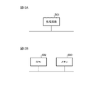
制御装置3における監視部301、消費電力推定部302、温度上昇率推定部303、切替え部304、猶予時間推定部305、冷却対象選択部306、冷却時間設定部307及び冷却制御部308の各機能は、処理回路501により実現される。処理回路501は、図12Aに示すように、専用のハードウェアであってもよいし、図12Bに示すように、メモリ503に格納されるプログラムを実行するCPU(Central Processing Unit、中央処理装置、処理装置、演算装置、マイクロプロセッサ、マイクロコンピュータ、プロセッサ、又はDSP(Digital Signal Processor)ともいう)502であってもよい。
Finally, a hardware configuration example of the
Functions of a
処理回路501が専用のハードウェアである場合、処理回路501は、例えば、単一回路、複合回路、プログラム化したプロセッサ、並列プログラム化したプロセッサ、ASIC(Application Specific Integrated Circuit)、FPGA(Field Programmable Gate Array)、又はこれらを組み合わせたものが該当する。監視部301、消費電力推定部302、温度上昇率推定部303、切替え部304、猶予時間推定部305、冷却対象選択部306、冷却時間設定部307及び冷却制御部308の各部の機能それぞれを処理回路501で実現してもよいし、各部の機能をまとめて処理回路501で実現してもよい。
When the
処理回路501がCPU502の場合、監視部301、消費電力推定部302、温度上昇率推定部303、切替え部304、猶予時間推定部305、冷却対象選択部306、冷却時間設定部307及び冷却制御部308の機能は、ソフトウェア、ファームウェア、又はソフトウェアとファームウェアとの組み合わせにより実現される。ソフトウェア及びファームウェアはプログラムとして記述され、メモリ503に格納される。処理回路501は、メモリ503に記憶されたプログラムを読み出して実行することにより、各部の機能を実現する。すなわち、制御装置3は、処理回路501により実行されるときに、例えば図3,4に示した各ステップが結果的に実行されることになるプログラムを格納するためのメモリ503を備える。また、これらのプログラムは、監視部301、消費電力推定部302、温度上昇率推定部303、切替え部304、猶予時間推定部305、冷却対象選択部306、冷却時間設定部307及び冷却制御部308の手順及び方法をコンピュータに実行させるものであるともいえる。ここで、メモリ503としては、例えば、RAM(Random Access Memory)、ROM(Read Only Memory)、フラッシュメモリ、EPROM(Erasable Programmable ROM)、EEPROM(Electrically EPROM)等の不揮発性又は揮発性の半導体メモリ、磁気ディスク、フレキシブルディスク、光ディスク、コンパクトディスク、ミニディスク、又はDVD(Digital Versatile Disc)等が該当する。
When the
なお、監視部301、消費電力推定部302、温度上昇率推定部303、切替え部304、猶予時間推定部305、冷却対象選択部306、冷却時間設定部307及び冷却制御部308の各機能について、一部を専用のハードウェアで実現し、一部をソフトウェア又はファームウェアで実現するようにしてもよい。例えば、監視部301については専用のハードウェアとしての処理回路501でその機能を実現し、消費電力推定部302、温度上昇率推定部303、切替え部304、猶予時間推定部305、冷却対象選択部306、冷却時間設定部307及び冷却制御部308については処理回路501がメモリ503に格納されたプログラムを読み出して実行することによってその機能を実現することが可能である。
In addition, regarding each function of the
このように、処理回路501は、ハードウェア、ソフトウェア、ファームウェア、又はこれらの組み合わせによって、上述の各機能を実現することができる。
Thus, the
なお、実施の形態の任意の構成要素の変形、若しくは実施の形態の任意の構成要素の省略が可能である。 It should be noted that any component of the embodiment can be modified, or any component of the embodiment can be omitted.
1 ショーケース、2 電力量計、3 制御装置、301 監視部、302 消費電力推定部、303 温度上昇率推定部、304 切替え部、305 猶予時間推定部、306 冷却対象選択部、307 冷却時間設定部、308 冷却制御部、501 処理回路、502 CPU、503 メモリ。 1 showcase, 2 electricity meter, 3 control device, 301 monitoring unit, 302 power consumption estimating unit, 303 temperature rise rate estimating unit, 304 switching unit, 305 grace time estimating unit, 306 cooling object selecting unit, 307 cooling time setting section, 308 cooling control section, 501 processing circuit, 502 CPU, 503 memory.
Claims (7)
前記ショーケース毎の冷却運転を停止した場合での庫内温度の上昇率及び前記監視部による監視結果に基づいて、前記ショーケース毎に、庫内温度が上限値に達するまでの猶予時間を推定する猶予時間推定部と、
非常用発電機の供給可能電力、前記ショーケース毎の冷却運転に必要な消費電力及び前記猶予時間推定部による推定結果に基づいて、前記ショーケースの中から、冷却対象とするショーケースを選択する冷却対象選択部と、
前記猶予時間推定部による推定結果に基づいて、前記冷却対象選択部により冷却対象として選択されたショーケースに対する冷却時間を設定する冷却時間設定部と、
前記冷却対象選択部により冷却対象として選択されたショーケースに対し、前記冷却時間設定部により設定された冷却時間だけ冷却を行うよう指示する冷却制御部とを備え、
前記猶予時間推定部は、前記冷却対象選択部により冷却対象として選択されたショーケースによる冷却運転が停止した場合、猶予時間の推定を再度行う
ことを特徴とする制御装置。 a monitoring unit that monitors the temperature inside the refrigerator for each of a plurality of showcases;
Based on the rate of increase of the temperature inside the refrigerator when the cooling operation of each showcase is stopped and the result of monitoring by the monitoring unit, the grace period until the temperature inside the refrigerator reaches the upper limit value is estimated for each showcase. a grace time estimation unit for
A showcase to be cooled is selected from among the showcases based on the power that can be supplied by the emergency power generator, the power consumption required for the cooling operation of each showcase, and the estimation result by the grace time estimation unit. a cooling target selection unit;
a cooling time setting unit that sets a cooling time for the showcase selected as a cooling target by the cooling target selection unit based on the estimation result of the grace time estimation unit;
a cooling control unit that instructs the showcase selected as a cooling target by the cooling target selection unit to be cooled for a cooling time set by the cooling time setting unit;
The control device, wherein the grace time estimating unit re-estimates the grace time when the cooling operation of the showcase selected as the object to be cooled by the cooling object selection unit is stopped.
ことを特徴とする請求項1記載の制御装置。 The cooling control unit controls, for the showcase selected as the object to be cooled by the object-to-be-cooled selection unit, until the cooling time set by the cooling time setting unit or the internal temperature becomes equal to or less than a threshold with respect to the set temperature. 2. The control device according to claim 1, which instructs to perform cooling.
ことを特徴とする請求項1又は請求項2記載の制御装置。 The cooling target selection unit selects the showcases to be cooled in order from the shortest grace time estimated by the grace time estimation unit, and calculates the total power consumption required for the cooling operation of the showcases selected as the cooling targets. 3. The control device according to claim 1, wherein the selection of cooling objects is repeated so that the sum does not exceed the suppliable power of the emergency power generator.
ことを特徴とする請求項1から請求項3のうちの何れか1項記載の制御装置。 The cooling time setting unit may set, as the cooling time, the time until the minimum grace time of all the showcases not selected as cooling objects by the cooling object selection unit becomes equal to or less than a predetermined value. 4. A control device as claimed in any one of claims 1 to 3.
前記監視部による監視結果に基づいて、前記ショーケース毎に、冷却運転に必要な消費電力を推定する消費電力推定部と、
前記監視部による監視結果に基づいて、前記ショーケース毎に、冷却運転を停止した場合での庫内温度の上昇率を推定する温度上昇率推定部とを備え、
前記猶予時間推定部は、前記温度上昇率推定部による推定結果を用いて、前記ショーケース毎に、庫内温度が上限値に達するまでの猶予時間を推定し、
前記冷却対象選択部は、前記消費電力推定部による推定結果を用いて、前記ショーケースの中から、冷却対象とするショーケースを選択する
ことを特徴とする請求項1から請求項4のうちの何れか1項記載の制御装置。 The monitoring unit monitors the internal temperature and power consumption for each showcase,
a power consumption estimating unit for estimating the power consumption required for cooling operation for each showcase based on the results of monitoring by the monitoring unit;
a temperature rise rate estimating unit for estimating, for each showcase, a rate of increase in internal temperature when the cooling operation is stopped, based on the results of monitoring by the monitoring unit;
The grace time estimating unit estimates the grace time until the internal temperature reaches the upper limit value for each showcase using the estimation result by the temperature rise rate estimating unit,
The cooling target selection unit selects a showcase to be cooled from among the showcases using the estimation result by the power consumption estimation unit. A control device according to any one of the preceding claims.
ことを特徴とする請求項5記載の制御装置。 The temperature rise rate estimating unit estimates the temperature rise rate multiple times from changes in temperature and the time from when the cooling operation is stopped until the cooling operation is started during normal operation for each showcase, and calculates the most recent 6. The control device according to claim 5, wherein a final temperature rise rate is calculated from a moving average of temperature rise rates obtained a plurality of times.
猶予時間推定部が、前記ショーケース毎の冷却運転を停止した場合での庫内温度の上昇率及び前記監視部による監視結果に基づいて、前記ショーケース毎に、庫内温度が上限値に達するまでの猶予時間を推定するステップと、
冷却対象選択部が、非常用発電機の供給可能電力、前記ショーケース毎の冷却運転に必要な消費電力及び前記猶予時間推定部による推定結果に基づいて、前記ショーケースの中から、冷却対象とするショーケースを選択するステップと、
冷却時間設定部が、前記猶予時間推定部による推定結果に基づいて、前記冷却対象選択部により冷却対象として選択されたショーケースに対する冷却時間を設定するステップと、
冷却制御部が、前記冷却対象選択部により冷却対象として選択されたショーケースに対し、前記冷却時間設定部により設定された冷却時間だけ冷却を行うよう指示するステップとを有し、
前記猶予時間推定部は、前記冷却対象選択部により冷却対象として選択されたショーケースによる冷却運転が停止した場合、猶予時間の推定を再度行う
ことを特徴とする制御方法。 a step in which the monitoring unit monitors the temperature inside the refrigerator for each of a plurality of showcases;
The grace time estimating unit determines that the temperature inside the refrigerator reaches the upper limit value for each showcase based on the rate of increase of the temperature inside the refrigerator when the cooling operation of each showcase is stopped and the result of monitoring by the monitoring unit. estimating a grace time to
A cooling object selection unit selects a cooling object from the showcase based on the suppliable power of the emergency power generator, the power consumption required for the cooling operation of each showcase, and the estimation result by the grace time estimation unit. selecting a showcase to perform;
a cooling time setting unit setting a cooling time for the showcase selected as a cooling target by the cooling target selection unit, based on the estimation result by the grace time estimation unit;
a cooling control unit instructing the showcase selected as a cooling target by the cooling target selection unit to cool for the cooling time set by the cooling time setting unit;
The control method, wherein the grace time estimating unit re-estimates the grace time when the cooling operation of the showcase selected as the object to be cooled by the cooling object selection unit is stopped.
Priority Applications (1)
| Application Number | Priority Date | Filing Date | Title |
|---|---|---|---|
| JP2021071521A JP2022166364A (en) | 2021-04-21 | 2021-04-21 | Control device and control method |
Applications Claiming Priority (1)
| Application Number | Priority Date | Filing Date | Title |
|---|---|---|---|
| JP2021071521A JP2022166364A (en) | 2021-04-21 | 2021-04-21 | Control device and control method |
Publications (1)
| Publication Number | Publication Date |
|---|---|
| JP2022166364A true JP2022166364A (en) | 2022-11-02 |
Family
ID=83851636
Family Applications (1)
| Application Number | Title | Priority Date | Filing Date |
|---|---|---|---|
| JP2021071521A Pending JP2022166364A (en) | 2021-04-21 | 2021-04-21 | Control device and control method |
Country Status (1)
| Country | Link |
|---|---|
| JP (1) | JP2022166364A (en) |
Citations (5)
| Publication number | Priority date | Publication date | Assignee | Title |
|---|---|---|---|---|
| JPH10339546A (en) * | 1997-06-06 | 1998-12-22 | Mitsubishi Electric Corp | Demand control device for refrigerator |
| JP2008011618A (en) * | 2006-06-28 | 2008-01-17 | Sanyo Electric Co Ltd | Demand controller |
| JP2015037361A (en) * | 2013-08-13 | 2015-02-23 | 三菱電機株式会社 | Demand controller and demand control method |
| JP2019078444A (en) * | 2017-10-24 | 2019-05-23 | 福島工業株式会社 | Cooling box |
| WO2020217424A1 (en) * | 2019-04-25 | 2020-10-29 | 三菱電機株式会社 | Heat-source unit and refrigeration cycle device provided with same |
-
2021
- 2021-04-21 JP JP2021071521A patent/JP2022166364A/en active Pending
Patent Citations (5)
| Publication number | Priority date | Publication date | Assignee | Title |
|---|---|---|---|---|
| JPH10339546A (en) * | 1997-06-06 | 1998-12-22 | Mitsubishi Electric Corp | Demand control device for refrigerator |
| JP2008011618A (en) * | 2006-06-28 | 2008-01-17 | Sanyo Electric Co Ltd | Demand controller |
| JP2015037361A (en) * | 2013-08-13 | 2015-02-23 | 三菱電機株式会社 | Demand controller and demand control method |
| JP2019078444A (en) * | 2017-10-24 | 2019-05-23 | 福島工業株式会社 | Cooling box |
| WO2020217424A1 (en) * | 2019-04-25 | 2020-10-29 | 三菱電機株式会社 | Heat-source unit and refrigeration cycle device provided with same |
Similar Documents
| Publication | Publication Date | Title |
|---|---|---|
| EP2026022B1 (en) | Extended cold (battery backup) refrigerator | |
| CN104570784B (en) | Determine the stealing ability of environmental control system controller | |
| US6860431B2 (en) | Strategic-response control system for regulating air conditioners for economic operation | |
| EP3447896B1 (en) | Motor control systems | |
| US8984902B2 (en) | System to control external condensation on a refrigerator | |
| JP4822303B1 (en) | Showcase control system and program | |
| US20020024332A1 (en) | Methods and apparatus for controlling electric appliances during reduced power conditions | |
| JP2009225629A (en) | Demand control system | |
| US20110198340A1 (en) | Triac control of positive temperature coefficient (ptc) heaters in room air conditioners | |
| JPS6122173A (en) | Defrostation controller | |
| JP5378630B1 (en) | Electric compressor control method, control device, and refrigerator | |
| JP3315741B2 (en) | Demand control device and demand control system | |
| JP2008164274A (en) | Air conditioner and control method thereof | |
| JP5936714B2 (en) | System controller, facility management system, demand control method and program | |
| JP5090580B1 (en) | Heating system and heating system control method | |
| CN108206521B (en) | Control method and device for demand response and electric power management and control platform | |
| KR20190106292A (en) | Refrigerator system and Control method of the same | |
| JPWO2016046991A1 (en) | Air-conditioning refrigeration complex equipment | |
| JP2018014856A (en) | Power controller and program | |
| CA2938489C (en) | Stir-cycle motor | |
| EP1936293B1 (en) | Controller for air conditioner | |
| KR100531083B1 (en) | A power control apparatus and method of multi-air conditioner | |
| CN114992969A (en) | Time-sharing power utilization control method and device and refrigerator | |
| JPH11325687A (en) | refrigerator | |
| JP6567354B2 (en) | refrigerator |
Legal Events
| Date | Code | Title | Description |
|---|---|---|---|
| A621 | Written request for application examination |
Free format text: JAPANESE INTERMEDIATE CODE: A621 Effective date: 20231204 |
|
| A977 | Report on retrieval |
Free format text: JAPANESE INTERMEDIATE CODE: A971007 Effective date: 20240628 |
|
| A131 | Notification of reasons for refusal |
Free format text: JAPANESE INTERMEDIATE CODE: A131 Effective date: 20240730 |
|
| A521 | Request for written amendment filed |
Free format text: JAPANESE INTERMEDIATE CODE: A523 Effective date: 20240913 |
|
| A02 | Decision of refusal |
Free format text: JAPANESE INTERMEDIATE CODE: A02 Effective date: 20250107 |