JP2022188564A - Phosphor wheel device and light emitting module - Google Patents
Phosphor wheel device and light emitting module Download PDFInfo
- Publication number
- JP2022188564A JP2022188564A JP2021096699A JP2021096699A JP2022188564A JP 2022188564 A JP2022188564 A JP 2022188564A JP 2021096699 A JP2021096699 A JP 2021096699A JP 2021096699 A JP2021096699 A JP 2021096699A JP 2022188564 A JP2022188564 A JP 2022188564A
- Authority
- JP
- Japan
- Prior art keywords
- light
- phosphor wheel
- detection
- wavelength conversion
- section
- Prior art date
- Legal status (The legal status is an assumption and is not a legal conclusion. Google has not performed a legal analysis and makes no representation as to the accuracy of the status listed.)
- Granted
Links
Images


Landscapes
- Projection Apparatus (AREA)
Abstract
【課題】蛍光体ホイールの回転の向きを検出できる仕組みを有する装置を提供する。【解決手段】蛍光体ホイール100の第1検出部31及び第2検出部32は、回転軸A1を中心とし少なくとも第1検出部31及び第2検出部32の一方が通過する円周の最小半径の値を第3の値とし、回転軸A1を中心とし少なくとも第1検出部31及び第2検出部32の一方が通過する円周の最大半径を第4の値としたときに、回転軸A1を中心とし半径が第3の値以上第4の値以下の範囲にある第5の値である円周上において、円周上を通過する第1検出部31の長さと第2検出部32の長さとが異なるように配される。【選択図】図2An object of the present invention is to provide a device having a mechanism capable of detecting the direction of rotation of a phosphor wheel. A first detection part (31) and a second detection part (32) of a phosphor wheel (100) have a minimum radius of a circumference around a rotation axis (A1) through which at least one of the first detection part (31) and the second detection part (32) passes. is the third value, and the maximum radius of the circumference through which at least one of the first detection unit 31 and the second detection unit 32 passes is the fourth value, the rotation axis A1 is the fifth value in the range of the third value or more and the fourth value or less, the length of the first detection unit 31 passing on the circumference and the length of the second detection unit 32 arranged to differ in length. [Selection drawing] Fig. 2
Description
本開示は、蛍光体ホイール装置及び発光モジュールに関する。 The present disclosure relates to phosphor wheel devices and light emitting modules.
発光素子と蛍光体ホイール装置とを備え、発光素子からの光を蛍光体ホイールに入射させて、蛍光を取り出す技術が知られている。また、特許文献1には、蛍光体層が設けられた回転板の異常を検出するために、検出パターンからの光を検出する検出器が設けられる照明装置が開示されている。 A technique is known in which a light-emitting element and a phosphor wheel device are provided, and light from the light-emitting element is made incident on the phosphor wheel to extract fluorescence. Further, Patent Document 1 discloses an illumination device provided with a detector for detecting light from a detection pattern in order to detect an abnormality in a rotating plate provided with a phosphor layer.
本開示は、蛍光体ホイールの回転の向きを検出できる仕組みを有する装置を提供することを目的とする。 An object of the present disclosure is to provide a device having a mechanism capable of detecting the direction of rotation of a phosphor wheel.
実施形態に開示される蛍光体ホイール装置は、基板と、光の波長を変換する1または複数の蛍光体を含み前記基板の上に設けられる波長変換部と、前記基板の上に設けられる第1検出部及び第2検出部と、を有する蛍光体ホイールと、前記蛍光体ホイールを回転自在に支持する支持部材と、前記蛍光体ホイールの回転軸を中心に前記蛍光体ホイールを回転させる駆動部と、を備え、前記波長変換部は、前記回転軸を中心とし半径が第1の値である第1円周を通過するように配され、前記第1検出部及び第2検出部は、前記回転軸を中心とし半径が前記第1の値とは異なる第2の値である第2円周を通過するように配され、前記第1検出部及び第2検出部は、前記回転軸を中心とし少なくとも前記第1検出部及び第2検出部の一方が通過する円周の最小半径の値を第3の値とし、前記回転軸を中心とし少なくとも前記第1検出部及び第2検出部の一方が通過する円周の最大半径を第4の値としたときに、前記回転軸を中心とし半径が第3の値以上第4の値以下の範囲にある第5の値である円周上において、当該円周上を通過する前記第1検出部の長さと、当該円周上を通過する前記第2検出部の長さと、が異なるように配される。 A phosphor wheel device disclosed in an embodiment comprises a substrate, a wavelength conversion unit provided on the substrate including one or more phosphors for converting the wavelength of light, and a first phosphor provided on the substrate. a phosphor wheel having a detection unit and a second detection unit; a support member that rotatably supports the phosphor wheel; and a driving unit that rotates the phosphor wheel about a rotation axis of the phosphor wheel. , wherein the wavelength conversion section is arranged so as to pass through a first circumference centered on the rotation axis and having a radius of a first value, and the first detection section and the second detection section are configured to The first detection unit and the second detection unit are arranged so as to pass through a second circumference whose center is the axis and whose radius is a second value different from the first value, and the first detection unit and the second detection unit are centered on the rotation axis. A value of a minimum radius of a circumference through which at least one of the first detection section and the second detection section passes is set as a third value, and at least one of the first detection section and the second detection section is centered on the rotation axis. On a circle centered on the rotation axis and having a fifth value in the range of a third value or more and a fourth value or less, where the maximum radius of the passing circle is a fourth value, The length of the first detection section passing on the circumference and the length of the second detection section passing on the circumference are arranged to be different.
また、実施形態に開示される発光モジュールは、実施形態に開示される蛍光体ホイール装置と、第1波長をピーク波長とする光を前記波長変換部に出射する1または複数の第1発光装置と、前記蛍光体ホイールの回転によって前記第1検出部及び第2検出部が通過する位置に検出光を出射する発光部と、前記検出光を受光する受光部と、を有する回転検出ユニットと、を備える。 Further, the light-emitting module disclosed in the embodiment includes the phosphor wheel device disclosed in the embodiment, and one or more first light-emitting devices that emit light having a peak wavelength of a first wavelength to the wavelength conversion unit. and a rotation detection unit having a light emitting section that emits detection light to a position through which the first detection section and the second detection section pass by rotation of the phosphor wheel, and a light receiving section that receives the detection light. Prepare.
本開示の実施形態によれば、蛍光体ホイールの回転の向きを検出できるため、正しい回転の向きで動作しているかを確認することができる。 According to the embodiments of the present disclosure, since the direction of rotation of the phosphor wheel can be detected, it is possible to confirm whether the device is operating in the correct direction of rotation.
本明細書または特許請求の範囲において、三角形や四角形などの多角形に関しては、多角形の隅に角丸め、面取り、角取り、丸取り等の加工が施された形状も含めて、多角形と呼ぶものとする。また、隅(辺の端)に限らず、辺の中間部分に加工が施された形状も同様に、多角形と呼ぶものとする。つまり、多角形をベースに残しつつ、部分的な加工が施された形状は、本明細書及び特許請求の範囲で記載される“多角形”の解釈に含まれるものとする。 In the present specification and claims, regarding polygons such as triangles and quadrilaterals, polygons include shapes with corners rounded, chamfered, chamfered, rounded, etc. shall be called. In addition, not only the corners (ends of sides) but also shapes in which intermediate portions of sides are processed are called polygons. In other words, shapes that are partially processed while leaving a polygon as a base shall be included in the interpretation of "polygon" described in this specification and claims.
また、多角形に限らず、台形や円形や凹凸など、特定の形状を表す言葉についても同様である。また、その形状を形成する各辺を扱う場合も同様である。つまり、ある辺において、隅や中間部分に加工が施されていたとしても、“辺”の解釈には加工された部分も含まれる。なお、部分的な加工のない“多角形”や“辺”を、加工された形状と区別する場合は“厳密な”を付して、例えば、“厳密な四角形”などと記載するものとする。 The same applies to words that express specific shapes, such as trapezoids, circles, and unevenness, in addition to polygons. The same is true when dealing with each side forming the shape. In other words, even if a corner or intermediate portion of a certain side is processed, the processed portion is also included in the interpretation of "side". When distinguishing a partially unprocessed "polygon" or "side" from a processed shape, add "strict" and describe it as, for example, "strict quadrilateral". .
また、本明細書または特許請求の範囲において、上下、左右、表裏、前後、手前と奥などの表現は、相対的な位置、向き、方向などの関係を述べるに過ぎず、使用時における関係と一致していなくてもよい。例えば、部品と完成品において、部品の上面が、完成品の側面に位置するように実装される場合でも、その部品にとっての上面は変わらない。 In addition, in this specification or the scope of claims, expressions such as up and down, left and right, front and back, front and back, front and back only describe the relationship of relative positions, orientations, directions, etc., and the relationship during use They do not have to match. For example, even if a component and a finished product are mounted so that the top surface of the component is located on the side surface of the finished product, the top surface for the component does not change.
また、本明細書または特許請求の範囲において、ある構成要素に関し、これに該当するものが複数あり、それぞれを区別して表現する場合に、その構成要素の頭に“第1”、“第2”と付記して区別することがある。 In addition, in the present specification or the scope of claims, when there are a plurality of items corresponding to a certain component, and each of them is separately expressed, "first" and "second" are added to the beginning of the component. can be distinguished by adding
以下に、図面を参照しながら、本発明を実施するための形態を説明する。ただし、示される形態は、本発明の技術思想が具体化されたものではあるが、本発明を限定するものではない。また、以下の説明において、同一の名称、符号については同一もしくは同質の部材を示しており、重複した説明は適宜省略することがある。なお、各図面が示す部材の大きさや位置関係等は、理解の便宜を図るために誇張していることがある。 EMBODIMENT OF THE INVENTION Below, the form for implementing this invention is demonstrated, referring drawings. However, although the shown form embodies the technical idea of the present invention, it does not limit the present invention. Also, in the following description, the same names and symbols indicate the same or homogeneous members, and redundant description may be omitted as appropriate. Note that the sizes and positional relationships of members shown in each drawing may be exaggerated for the convenience of understanding.
<実施形態>
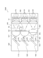
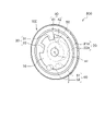
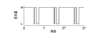
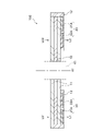
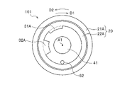
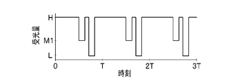
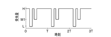
実施形態に係る発光モジュール1000を説明する。図1乃至図4は、発光モジュール1000の例示的な一形態を示す平面図である。図1は、回転検出ユニット60を省略している。また、図1は、光線の一部を点線で例示している。図2は、蛍光体ホイール装置200及び回転検出ユニット60の斜視図である。図3Aは、蛍光体ホイール100を光の出力面側から見た平面図である。図3Aは、支持部材40の心棒41と、回転検出ユニット60の受光部62とを併せて記している。図3B、図3Cは、回転検出ユニット60における受光量の時間変化の一例を示すグラフである。図4は、図3Aに示す蛍光体ホイール100のIV-IV断面線における断面図である。
<Embodiment>
A light-emitting
発光モジュール1000は、複数の構成要素を備える。複数の構成要素には、1または複数の第1発光装置410、蛍光体ホイール装置200及び回転検出ユニット60が含まれる。発光モジュール1000は、1または複数の第1発光装置410から出射される光に基づき波長変換された光を外部へと出射させる。発光モジュール1000は、筐体600に収納されている。
The
複数の構成要素には、1または複数の光学部材が含まれてもよい。1または複数の光学部材には、例えば、集光レンズ、コリメートレンズ及びミラーが含まれる。なお、これら以外の光学部材を有していてもよい。また、これらの光学部材の一部あるいは全部を有していなくてよい。図1に例示される発光モジュール1000は、複数の第1発光装置410を有し、複数の第1発光装置410から出射された光を制御する複数の光学部材を有している。複数の光学部材には、第1集光レンズ511、第1コリメートレンズ512及び第1ミラー513が含まれる。
The multiple components may include one or more optical members. The one or more optical members include, for example, condensing lenses, collimating lenses and mirrors. In addition, you may have an optical member other than these. Also, some or all of these optical members may not be provided. A light-emitting
発光モジュール1000は、1または複数の第2発光装置420を有して構成することができる。発光モジュール1000は、1または複数の第3発光装置430をさらに有して構成することができる。図1に例示される発光モジュール1000は、複数の第2発光装置420及び複数の第3発光装置430を有している。そして、複数の第2発光装置420から出射された光を制御する複数の光学部材として、第2集光レンズ521、第2コリメートレンズ522及び第2ミラー523を有し、複数の第3発光装置430から出射された光を制御する光学部材として、第3集光レンズ531、拡散部材300、第3コリメートレンズ532及び第3ミラー533を有している。
The
図1に例示される発光モジュール1000は、複数の第1発光装置410及び複数の第2発光装置420から出射される光を波長変換し、波長変換された光を外部へと出射する。また、発光モジュール1000は、複数の第3発光装置430から出射される光を波長変換せずに外部へと出射する。発光モジュール1000は、これらの光を制御して、それぞれ別個に又は合成して外部へと出射させる。別個の光又は合成された光は、例えば、筐体600に形成される光取出口700から外部へ取り出すことができる。
The
以上述べた各構成要素について説明する。
(第1発光装置410)
1または複数の第1発光装置410は、第1波長をピーク波長とする光を出射する。ここでは、複数の第1発光装置410を同一平面に配置して用いている。第1発光装置410の発光素子は同じ色の光を出射する。なお、異なる色の光を出射してもよい。
Each component mentioned above is demonstrated.
(First light emitting device 410)
The one or more first
発光素子には、一例として、半導体レーザ素子が採用される。また、LED、有機EL、などが採用されてもよい。例えば、発光素子は、その発光ピーク波長が365nm~494nmの範囲内にある光を採用することができる。なお、この範囲外のピーク波長を有する光を採用してもよい。また、可視光の波長範囲に限らなくてもよい。また、紫外光の波長範囲にピーク波長を有する光であってもよい。 A semiconductor laser element is adopted as an example of the light emitting element. Alternatively, an LED, an organic EL, or the like may be employed. For example, the light emitting element can employ light whose emission peak wavelength is within the range of 365 nm to 494 nm. In addition, you may employ|adopt the light which has a peak wavelength outside this range. Also, the range of wavelengths is not limited to visible light. Alternatively, light having a peak wavelength in the wavelength range of ultraviolet light may be used.
発光素子には、青色の光を出射する発光素子が含まれていてもよい。また、発光素子には、紫色の光を出射する発光素子が含まれていてもよい。なお、これら以外の色の光を出射する発光素子であってもよい。 The light-emitting element may include a light-emitting element that emits blue light. Further, the light-emitting element may include a light-emitting element that emits violet light. Note that a light-emitting element that emits light of a color other than these may be used.
ここでの青色の光は、その発光ピーク波長が430nm~494nmの範囲内にある光をいうものとする。紫色の光は、その発光ピーク波長が365nm~430nmの範囲内にある光をいうものとする。青色、また、紫色の光を発する発光素子として、窒化物半導体を含む半導体レーザ素子が挙げられる。窒化物半導体としては、例えば、GaN、InGaN、及びAlGaNを用いることができる。 Here, blue light refers to light having an emission peak wavelength within the range of 430 nm to 494 nm. Violet light refers to light whose emission peak wavelength is in the range of 365 nm to 430 nm. A semiconductor laser device containing a nitride semiconductor is given as a light-emitting device that emits blue or violet light. GaN, InGaN, and AlGaN, for example, can be used as nitride semiconductors.
(蛍光体ホイール装置200)
蛍光体ホイール装置200は、蛍光体ホイール100、支持部材40及び駆動部50を有している。蛍光体ホイール装置200は、蛍光体ホイール100が有する波長変換部20により、入射光とは異なる波長の出射光を出力することができる。
(Phosphor wheel device 200)
The
(蛍光体ホイール100)
蛍光体ホイール100は、基板10を有する。蛍光体ホイール100はさらに、基板10の上に設けられる、波長変換部20、第1検出部31及び第2検出部32を有する。蛍光体ホイール100は回転軸A1を有し、回転軸A1を中心に回転している状態で使用される。蛍光体ホイール100の一方の面は光の入力面であり、入力面の反対面は光の出力面である。
(Phosphor wheel 100)
A
(基板10)
基板10は板状の部材である。基板10の形状は例えば円盤状である。蛍光体ホイール100では、図2に示すように、基板10は円盤状の透光性基板である。透光性基板には、例えばサファイヤ基板を採用することができる。
(Substrate 10)
The
(第1検出部31及び第2検出部32)
図3Aに示すように、検出部30は、照射される光を遮り又は反射する領域である。検出部30は、第1検出部31及び第2検出部32を含む。また、検出部30はさらに、第3検出部を含む場合もある。検出部30は、照射される光のうち特定の波長の光を遮り又は反射できればよい。検出部30は、波長変換部20と同じ材料で形成することができる。例えば、検出部30に照射される赤外光に対し、YAG蛍光体で形成される検出部30を採用することができる。第1検出部31と第2検出部32とは、例えば、透光性の基板10の表面上に設けられる。
(
As shown in FIG. 3A, the
(波長変換部20)
波長変換部20は、光の波長を変換する1または複数の蛍光体を含む。蛍光体は、波長が特定の範囲にある光を励起光として吸収し、吸収した光とは異なる波長の光を蛍光として放出する性質を有する。青色の光を励起光とする蛍光体としては、例えばYAGやLAGなどのガーネット系蛍光体を採用することができる。
(Wavelength converter 20)
The
波長変換部20は、蛍光体の励起光となる波長範囲にある光を波長変換して出射する。ただし、励起光となる波長範囲であっても、一部の光が波長変換されずに透過される場合がある。このため、波長変換部20から出射される光には、波長変換部20を透過する入射光が含まれる場合がある。
The
波長変換部20は、例えば円環状や多角形の環状とすることができる。また、波長変換部20は、複数の波長変換領域を有して構成することができる。図3Aに例示される蛍光体ホイール100では、第1波長変換領域21A及び第2波長変換領域22Aが、互いに重ならない円環状の領域で形成されている。第1波長変換領域21Aは、第2波長変換領域22Aの外側に設けられている。第1波長変換領域21Aと第2波長変換領域22Aは、互いに異なる種類の蛍光体を含む。なお、互いに同じ種類の蛍光体を含んでもよい。例えば、第1波長変換領域21AはLAG蛍光体を含み、第2波長変換領域22AはYAG蛍光体を含むことができる。
The
波長変換部20、第1検出部31及び第2検出部32は、基板10の上に設けられる。蛍光体ホイール100が回転軸A1を中心に回転するとき、波長変換部20、第1検出部31及び第2検出部32は、回転軸A1を中心とする円周を描く。
The
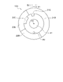
図3Aに示すように、回転軸A1を原点とする半径Rの座標軸が記載されている。第1波長変換領域21Aは、回転軸A1を中心とし半径が第1の値R1である第1円周を通過するように配されている。なお、第2波長変換領域22Aは、回転軸A1を中心として、第2波長変換領域22Aを通過する円周の半径の値を第1の値R1としてもよい。第2波長変換領域22Aを通過する円周の半径の値は、第1波長変換領域21Aを通過する円周の半径の値よりも小さな値である。第1検出部31及び第2検出部32は、回転軸A1を中心とし半径が第1の値R1とは異なる第2の値R2である第2円周を通過するように配されている。ここで、第1検出部31及び第2検出部32の少なくとも一方が通過する円周のうち、最小半径である円周の半径を第3の値R3とし、最大半径である円周の半径を第4の値R4とする。第2の値R2は、第3の値R3以上、第4の値R4以下となる。
As shown in FIG. 3A, coordinate axes with a radius R are described with the rotation axis A1 as the origin. The first
図3Aに例示する蛍光体ホイール100では、波長変換部20は、回転軸A1を中心に円環状に設けられている。そして、第1検出部31と第2検出部32とは、蛍光体ホイール100の回転方向における幅が異なり半径方向における幅が同じであるように、円環状の波長変換部20に沿って波長変換部20と一体に設けられている。
In the
第1検出部31及び第2検出部32は、一例として、第2波長変換領域22Aに接続して形成されている。第1検出部31、第2検出部32及び第2波長変換領域22Aは、一体的に形成することができる。なお、別体に形成されてもよい。
As an example, the
第1検出部31及び第2検出部32は、蛍光体ホイール100の回転方向に沿って配置されており、異なる形状になるように形成されている。第1検出部31及び第2検出部32は、回転方向に対して長さが異なる。ここでは、一例として、第1検出部31及び第2検出部32を、第2波長変換領域22Aの内周側に形成している。また、第1検出部31及び第2検出部32は、回転方向に離隔しており、かつ、回転方向の長さが異なるように形成されている。
The
図4に例示されるように、蛍光体ホイール100は、基板10を透光性とし、基板10の両面にフィルタ層11を有して構成することができる。蛍光体ホイール100は、入力面から入射光L01、L02が入射され、出力面から出射光L1、L2を出射する。フィルタ層11の特性は、入射光を透過し、波長変換部20による波長変換後の光を反射するように設定される。フィルタ層11は、例えば誘電体多層膜である。波長変換部20は、蛍光体ホイール100の出力面側のフィルタ層11上に配置される。蛍光体ホイール100の入力面は、波長変換部20が配置されていない側の面である。このように配置することで、入射光L01、L02は、フィルタ層11により反射が抑えられ、透光性の基板10を透過して波長変換部20に到達することができる。そして、波長変換部20による波長変換後の光の一部が基板10側に向けて出射されても、フィルタ層11により出力面側に反射させて取り出すことができる。
As exemplified in FIG. 4, the
また、波長変換部20の上面及び側面と蛍光体ホイール100の側面とは、被覆層12によって被覆されてもよい。被覆層12により、波長変換部20のフィルタ層11及び基板10に対する固着強度が高められる。被覆層12は、透光性の材料で形成されている。
Also, the top and side surfaces of the
(支持部材40)
支持部材40は、心棒41及び支持板42を有する。支持板42は、心棒41を一定の向き及び位置に支持する。支持部材40は、蛍光体ホイール100を回転自在に支持する。
(Support member 40)
The
(駆動部50)
駆動部50は回転軸のまわりにトルクを発生させる。回転の速さ及び向きは、外部から制御することができる。駆動部50は、例えば電力が供給されることにより作動する電気モーターである。図2に例示する蛍光体ホイール装置200では、駆動部50の回転軸は支持部材40の心棒41と重なる。
(Driving unit 50)
The driving
(回転検出ユニット60)
回転検出ユニット60は、蛍光体ホイール100の回転の速さ及び向きを検出する。回転検出ユニット60は、一例として、発光部61及び受光部62を有する。発光部61は、発光素子を有し、検出のための所定の波長の光(以下、検出光と呼ぶものとする。)を出射する。受光部62は、発光部61からの検出光を受光素子で受光し受光量に対応する信号を出力する。回転検出ユニット60は、回転する蛍光体ホイール100の検出部30が通過する位置に検出光を照射する。発光部61及び受光部62は、例えば図2に示すように、蛍光体ホイール100を挟んで向かい合って配置される。このように配置することによって、受光部62は、発光部61から出射され蛍光体ホイール100を透過した検出光を検出することができる。
(Rotation detection unit 60)
The
発光部61から出射された光は、蛍光体ホイール100に入射する。蛍光体ホイール100が回転軸A1を中心に回転すると、発光部61から出射された光の蛍光体ホイール100上における軌跡は、回転軸A1を中心とし半径が第5の値R5である第5円周を描く。この光の軌跡上に、第1検出部31及び第2検出部32が設けられている。したがって、第5の値R5は、第3の値R3以上第4の値R4以下の範囲にある。第1検出部31と第2検出部32とは、第5円周上を通過する長さが異なるように配される。ここで、長さが異なるとは、一方の長さが0である場合も含む。なお、第5の値R5は、第3の値R3以上第4の値R4以下の範囲に含まれていればよく、第2の値R2と同じ値であってもよい。
Light emitted from the
蛍光体ホイール装置200は、蛍光体ホイール100の回転の速さ及び向きを検出するために、回転検出ユニット60を使用する。回転検出ユニット60は、発光部61が出射する光を回転する蛍光体ホイール100に照射し、その透過光又は反射光を受光部62で受光する。受光部62の受光量の時間変化から、蛍光体ホイール100の回転の速さ及び向きを検出することができる。
The
図2に示す回転検出ユニット60では、発光部61から出射される光の波長に対して、第1検出部31及び第2検出部32の透過率は、同じ円周上の他の領域の透過率よりも小さい。このため、蛍光体ホイール100が回転すると、受光部62による受光量は、第1検出部31及び第2検出部32が通過しているときは小さくなり、通過していないときは大きくなる。
In the
図3A~3Cにより、受光部62の受光量の時間変化について説明する。図3Aに例示する蛍光体ホイール100では、回転検出ユニット60は、蛍光体ホイール100の1回転(1周期T)につき2回の検出状態の変化が生じる。1回は第1検出部31を通過することによる検出状態の変化で、残りの1回は第2検出部32を通過することによる検出状態の変化である。第1検出部31と第2検出部32とでは同一円周上における蛍光体ホイール100の回転方向の幅が異なるため、一定の速さで回転する蛍光体ホイール100において、各検出状態が維持される時間の長さが異なる。なお、第1検出部31及び第2検出部32をまとめて検出部30として説明する場合がある。
3A to 3C, the temporal change in the amount of light received by the
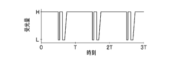
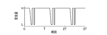
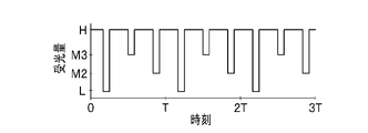
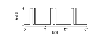
図3B、図3Cは、蛍光体ホイール100が一定の速さで回転するときに、回転検出ユニット60が出力する信号の時間変化の例であり、受光部62による受光量の時間変化に対応している。受光部62の受光量が相対的に大きいときが信号のHレベルに対応し、相対的に小さいときが信号のLレベルに対応している。すなわち、Lレベルが、検出光が検出部30上に入射している状態、Hレベルが、検出光が検出部30上に入射していない状態である。図3Bの検出状態に対して、蛍光体ホイール100の回転方向が逆になった場合の検出状態が図3Cである。
3B and 3C are examples of changes over time in the signal output from the
図3B及び図3Cのいずれも、蛍光体ホイール100が一回転する間(1周期Tの間)に2回、Lレベルの状態が検出される。1回目のLレベルの検出状態が検出されてからT1時間経過後に2回目のLレベルの検出状態が検出される。また、図3Bの場合、2回目のLレベルの検出状態が終わってから、次の周期の1回目のLレベルの検出状態が検出されるまでの時間(T2時間)は、T1時間よりも長い。なお、T1時間とT2時間はその違いが明確に検出できるだけの十分な時間差があればよく、T2時間の方がT1時間より短くてもよい。 In both FIGS. 3B and 3C, the L level state is detected twice during one rotation of the phosphor wheel 100 (during one cycle T). The second L level detection state is detected when T 1 time has passed since the first L level detection state was detected. In the case of FIG. 3B, the time (T2 hours) from the end of the second L level detection state to the detection of the first L level detection state in the next cycle is longer than T1 time. too long. It should be noted that the difference between the T1 time and the T2 time should be sufficient to clearly detect the difference, and the T2 time may be shorter than the T1 time.
図3Bでは、1回目のLレベルの検出状態が維持される時間よりも2回目のLレベルの検出状態が維持される時間の方が長い。一方で、図3Cでは、1回目のLレベルの検出状態が維持される時間よりも2回目のLレベルの検出状態が維持される時間の方が短い。このように、蛍光体ホイール100は、Lレベルの検出状態の長短の順序から回転の向きを検出することができる。なお、Hレベルの検出状態の長短の順序から回転の向きを検出することもできる。
In FIG. 3B, the time for which the L level detection state is maintained for the second time is longer than the time for which the L level detection state is maintained for the first time. On the other hand, in FIG. 3C, the time during which the low level detection state is maintained for the second time is shorter than the time during which the low level detection state is maintained for the first time. In this way, the
発光モジュール1000は、1または複数の第1発光装置410が、第1波長をピーク波長とする光を出射する。出射された光は、蛍光体ホイール装置200の波長変換部20に照射される。照射された光は、波長変換部20によって波長変換され、蛍光体ホイール装置200は第1の光を出力する。回転検出ユニット60は、蛍光体ホイール100の回転の速さ及び回転の向きを検出する。このため、蛍光体ホイール100の回転の速さ及び回転の向きを監視することができ、想定される通常の動作に対して誤動作を起こしていることがわかる。
In light-emitting
発光モジュール1000は、第1波長とは異なる第2波長をピーク波長とする光を出射する1または複数の第2発光装置420を備えてもよい。出射された光は、蛍光体ホイール装置200の波長変換部20に照射される。照射された光は、波長変換部20によって波長変換され、蛍光体ホイール装置200は第2の光を出力する。ただし、波長変換部20は、1または複数の第1発光装置410から出射された光が照射される第1波長変換領域21Aと、1または複数の第2発光装置420から出射された光が照射される第2波長変換領域22Aとを有している。このため、1または複数の第1発光装置410から出射された光と、1または複数の第2発光装置420から出射された光とを別個に波長変換することができる。
The
(光学部材)
光学部材は、光を屈折又は反射させることによって、入射される光を制御して出射する部材である。光学部材とは、例えば集光レンズ、拡散部材、コリメートレンズ又はミラーである。
(optical member)
An optical member is a member that controls and emits incident light by refracting or reflecting the light. An optical member is, for example, a condensing lens, a diffusing member, a collimating lens, or a mirror.
(集光レンズ)
第1集光レンズ511、第2集光レンズ521及び第3集光レンズ531は、入射される光を集光するように出射する。これらの各集光レンズは、単レンズでも複数の複合レンズから形成されていてもよい。
(拡散部材)
拡散部材300は、入射される光を拡散させて出射する。拡散部材300は、特定の方向に集中する光を拡散させて光を均一にしている。拡散部材300は、拡散物質を母材に含有させて形成することができる。また、拡散部材300は、表面及び裏面に凹凸を設けて形成することができる。拡散部材300は、光を均一にすることで、使用される目的に適する光としている。
(コリメートレンズ)
第1コリメートレンズ512、第2コリメートレンズ522及び第3コリメートレンズ532は、入射される光を平行光にして出射する。それぞれのコリメートレンズは、単レンズであっても複合レンズであってもよい。
(ミラー)
第1ミラー513、第2ミラー523及び第3ミラー533は、入射される光の一部を反射し、一部を透過させる。それぞれのミラーは、例えば、ダイクロイックミラーを使用することができる。
(Condenser lens)
The
(Diffusion member)
The
(collimating lens)
The
(mirror)
The
光学部材は、それぞれの発光装置から光取出口700までの光路中に配置されている。
第1集光レンズ511は、第1発光装置410から照射された光を集光して第1波長変換領域21Aに向けて出射する位置に設置されている。第2集光レンズ521は、第2発光装置420から照射された光を集光して第2波長変換領域22Aに向けて出射する位置に設置されている。第3集光レンズ531は、第3発光装置430から照射された光を集光して拡散部材300に向けて出射する位置に設置されている。
拡散部材300で拡散された光は、第3コリメートレンズ532に出射される。
The optical member is arranged in the optical path from each light emitting device to the
The
The light diffused by the
第1コリメートレンズ512は、第1波長変換領域21Aで波長変換された光を平行光として第1ミラー513に向かって出射する位置に設置されている。第2コリメートレンズ522は、第2波長変換領域22Aで波長変換された光を平行光として第2ミラー523に向かって出射する位置に設置されている。第3コリメートレンズ532は、拡散部材300で拡散された光を平行光として第3ミラー533に向かって出射する位置に設置されている。
第1ミラー513は、波長変換されて平行光となった第1の光を反射する位置に配置されている。第2ミラー523は、波長変換されて平行光となった第2の光を反射すると共に、第1の光を透過する位置に配置されている。第3ミラー533は、拡散されて平行光となった第3の光を反射すると共に、第1の光及び第2の光を透過する位置に配置されている。
The
The
(第2発光装置420、第3発光装置430)
すでに述べた第1発光装置410についての説明は、第2発光装置420及び第3発光装置430に共通する。
発光モジュール1000が、1または複数の第1発光装置410と、1または複数の第2発光装置420とを備える場合には、1または複数の第1発光装置410は複数の第1半導体レーザ素子を含み、1または複数の第2発光装置420は複数の第2半導体レーザ素子を含んで構成することができる。第1半導体レーザ素子と第2半導体レーザ素子とは、同じものでもよく、異なっていてもよい。
(Second
The description of the first
When light-emitting
発光モジュール1000が、1または複数の第3発光装置430をさらに備える場合には、1または複数の第3発光装置430は、複数の第3半導体レーザ素子を含んで構成することができる。第1半導体レーザ素子と第2半導体レーザ素子と第3半導体レーザ素子とは、同じものを含んでいてもよく、互いに異なっていてもよい。
If the light-emitting
次に、図1に例示される発光モジュール1000について、光の進路に着目して説明する。
第1発光装置410は、第1波長をピーク波長とする第1の光を出射する。出射された第1の光は第1集光レンズ511によって、蛍光体ホイール100の第1波長変換領域21Aに集光される。集光された光は、第1波長変換領域21Aの蛍光体によって波長変換され、蛍光体ホイール装置200から波長変換された第1の光が出射される。さらに、波長変換された第1の光は、第1コリメートレンズ512によって平行光L1Pとなる。平行光L1Pは、第1ミラー513によって反射され、反射された光が光取出口700の方向に進むL1P2である。
Next, the light-emitting
The first
蛍光体ホイール100は、第1集光レンズ511よりも第1コリメートレンズ512に近い位置に配置されている。蛍光体ホイール100は、第1コリメートレンズ512の近傍に配置されるのが好ましい。波長変換された光は、広い角度範囲で波長変換部20から出射されるため、波長変換部20を第1コリメートレンズ512に近付けることで、光の損失を低減することができる。また、同じ光量の光をコリメートする場合に、第1コリメートレンズ512のレンズ面の面積を小さく設計することができる。
The
第2発光装置420は、第2波長をピーク波長とする第2の光を出射する。出射された第2の光は第2集光レンズ521によって、蛍光体ホイール100の第2波長変換領域22Aに集光される。集光された光は、第2波長変換領域22Aの蛍光体によって波長変換され、蛍光体ホイール装置200から波長変換された第2の光が出射される。さらに、波長変換された第2の光は、第2コリメートレンズ522によって平行光L2Pとなる。平行光L2Pは、第2ミラー523によって反射され、反射された光が光取出口700の方向に進むL2P2である。
The second
第3発光装置430は、第3波長をピーク波長とする第3の光を出射する。出射された第3の光は第3集光レンズ531によって、拡散部材300に集光される。拡散部材300は集光された光を拡散して出射する。拡散された第3の光は、第3コリメートレンズ532によって平行光L3Pとなる。平行光L3Pは、第3ミラー533によって反射され、反射された光が光取出口700の方向に進むL3P2である。
図1に例示される発光モジュール1000の各構成要素は、光取出口700の方向に進む光L1P2、L2P2、L3P2の光軸が一致するように配置されている。このため、平行光L1P、L2P、L3Pは、光取出口700から同軸を通る別個の光又は合成された光として取り出すことができる。
The third
Each component of the
なお、図1では、光取出口700を一か所として説明したが、例えば、図10の発光モジュール1000Aが示すように、筐体600Aに第1光取出口710、第2光取出口720及び第3光取出口730を設けて、個別の光と合成された光とを分けて取り出すようにしてもよい。例えば、第1ミラー513Aが波長変換されて平行光となった第1の光L1Pの50%を反射し、50%を透過するようにして、第1ミラー513Aを透過して進む光L1P1を第1光取出口710から取り出すことができる。同様に、第2ミラー523Aが波長変換されて平行光となった第2の光L2Pの50%を反射し、50%を透過するようにして、第2ミラー523Aを透過して進む光L2P1を第2光取出口720から取り出すことができる。また、第3ミラー533Aが拡散されて平行光となった第3の光L3Pの50%を反射し、50%を透過するようにして、第3ミラー533Aを透過して進む光L3P1を第3光取出口730から取り出すことができる。また、別個の光又は合成された光は、光取出口700から取り出すことができる。
さらに、図1、図10において、第1発光装置410、第2発光装置420、第3発光装置430の後方に熱を除去するヒートシンクを設置する構成としてもよい。
In FIG. 1, the
Furthermore, in FIGS. 1 and 10, a configuration may be adopted in which a heat sink for removing heat is installed behind the first
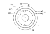
次に、各構成における変形例1乃至変形例5について、図5A乃至図9Cを参照して説明する。
(変形例1)
図5Aに示す蛍光体ホイール101では、波長変換部20は、回転軸A1を中心に円環状に設けられている。そして、第1検出部31A、第2検出部32Aは、蛍光体ホイール101の半径方向における幅が異なり回転方向における幅が同じであるように、円環状の波長変換部20に沿って波長変換部20と一体に設けられている。
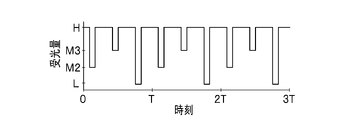
図5B、図5Cは、蛍光体ホイール101が一定の速さで回転するときに、回転検出ユニット60が出力する信号の時間変化の例である。図3B及び図3Cでは、Lレベルが検出される時間の違いを利用したが、図5B及び図5Cでは、受光部62における検出量の違いを利用する。つまり、検出光が第1検出部31Aを通過しているときに受光部62で受光される光の受光量と、検出光が第2検出部32Aを通過しているときに受光部62で受光される光の受光量とを異ならせる。例えば、第1検出部31A及び第2検出部32Aの一方においてM1レベルであり、他方においてM1レベルよりも低いLレベルとなっている。これは、第1検出部31Aよりも半径方向の幅が大きい第2検出部32Aが、より多くの光を遮るためである。例えば、検出光が照射される領域に対して、第1検出部31Aにおいて検出光の一部の領域だけが遮られ、第2検出部32Aにおいて検出光の全部が遮られるようにする。
Next, modified examples 1 to 5 in each configuration will be described with reference to FIGS. 5A to 9C.
(Modification 1)
In the
5B and 5C are examples of temporal changes in the signal output by the
(変形例2)
図6Aに示す蛍光体ホイール102では、波長変換部20は、回転軸A1を中心に円環状に設けられている。そして、第1検出部31B及び第2検出部32Bの少なくとも一方は、蛍光体ホイール102の回転方向における幅が、半径方向に一定ではない。ここで、回転方向における幅が一定ではないとは、回転方向の両端の回転軸A1を中心とする中心角が一定ではないという意味である。蛍光体ホイール102の第2検出部32Bは、半径が大きくなると中心角が大きくなっており、半径が増加する方向に回転方向における幅が増加している。
第1検出部31B、第2検出部32Bは、円環状の波長変換部20に沿って波長変換部20と一体に形成されている。第1検出部31Bと第2検出部32Bとは、回転方向の端部を除いて半径方向における幅が同じである。そして、第2検出部32Bの回転方向の両端は、半径方向に対する傾きが異なっている。また、第1検出部31B及び第2検出部32Bは、円環状の波長変換部20に沿って波長変換部20と一体に設けられている。
(Modification 2)
In the
The
図6B及び図6Cは、互いに回転方向が逆である蛍光体ホイール102が一定の速さで回転するときの、回転検出ユニット60が出力する信号の時間変化の例である。図6B及び図6Cにおいても、図3B及び図3Cと同様に、検出結果から回転の向きを検出することができる。
FIGS. 6B and 6C are examples of changes over time in signals output from the
(変形例3)
時分割式の光源では、蛍光体ホイール装置から出力される複数の波長の光を時分割で取り出して用いる場合もある。このような場合、波長変換部20に含まれる1または複数の蛍光体は、円環状の波長変換部20の回転方向に区画して設けられる。図7に示す蛍光体ホイール103は、蛍光体21B、22B、23Bを回転方向に区画して設けている。
第1検出部31Cと第2検出部32Cとは、蛍光体ホイール103の回転方向における幅が異なり半径方向における幅が同じであるように、円環状の波長変換部20に沿って波長変換部20と一体に設けられている。回転検出ユニット60が出力する信号の時間変化については、図3B及び図3Cと同様のことがいえる。なお、第1検出部31Cと第2検出部32Cとで、回転検出ユニット60の発光部61の光の波長における光吸収率が異なるようにすれば、図5B及び図5Cと同様のことがいえる。
(Modification 3)
A time-division light source sometimes extracts and uses light of a plurality of wavelengths output from a phosphor wheel device in a time-division manner. In such a case, one or a plurality of phosphors contained in the
The
(変形例4)
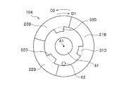
図8Aに示す蛍光体ホイール104は、蛍光体ホイール103と同様に、蛍光体21B、22B、23Bを回転方向に区画して設けている。そして、第1検出部31D、第2検出部32D及び第3検出部33Dは、円環状の波長変換部20に沿って波長変換部20と一体に設けられ、半径方向における幅が同じであり回転方向の幅も同じである。一方、第1検出部31Dと第2検出部32Dと第3検出部33Dとはそれぞれ、検出光に対する光吸収率が異なる。
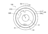
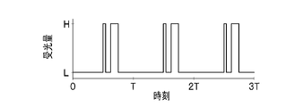
図8B及び図8Cは、蛍光体ホイール104が一定の速さで回転するときに、回転検出ユニット60が出力する信号の時間変化の例である。図8B及び図8Cに示すように、検出光が第1検出部31D、第2検出部32D及び第3検出部33Dのいずれを通過しているかは、検出状態のレベルの違いから特定できる。D1回転で回転する図8Bでは、それぞれ異なるレベルのL、M3、M2が順に現れており、D2回転で回転する図8Cでは、L、M2、M3が順に現れている。このように、L、M2、M3のレベルが検出される順番から回転の向きを検出することができる。
(Modification 4)
Similar to the
8B and 8C are examples of changes over time in signals output by the
(変形例5)
回転検出ユニット60は、反射光を利用して回転を検出してもよい。図9Aに示す例では、発光部61が出射する光を回転する蛍光体ホイール105に照射し、その反射光を受光部62で受光する。このため、第1検出部31E及び第2検出部32Eは、光反射性の表面を備え、回転検出ユニット60の発光部61と受光部62とは蛍光体ホイール105の同じ側に配置される。
図9B、図9Cは、蛍光体ホイール105が一定の速さで回転するときに、回転検出ユニット60が出力する信号の時間変化の例である。図3B及び図3Cの場合は、検出光が検出部30を通過しているときに受光量はLレベルであり、検出光が検出部30を通過していないときに受光量はHレベルであったが、図9B及び図9Cの場合は、検出光が検出部30を通過しているときに受光量がHレベルとなり、検出光が検出部30を通過していないときに受光量はLレベルとなる。この場合も、同様の原理から、回転の向きを検出することができる。
(Modification 5)
The
9B and 9C are examples of temporal changes in signals output from the
第1検出部及び第2検出部は、波長変換部の1または複数の蛍光体に含まれる1以上の蛍光体を含むようにしてもよい。
実施形態及び変形例において、検出部は、円環状の波長変換部に沿って、それぞれが隣接する波長変換部と同じ材料で一体に形成してもよい。すなわち、検出部は、円環状の波長変換部の内側又は外側に、波長変換部の突起のように設けられてもよい。
The first detection section and the second detection section may include one or more phosphors contained in one or more phosphors of the wavelength conversion section.
In embodiments and modifications, the detectors may be integrally formed of the same material as the wavelength converters adjacent to each other along the annular wavelength converters. That is, the detection section may be provided inside or outside the annular wavelength conversion section like a projection of the wavelength conversion section.
例えば、実施形態の蛍光体ホイール100において、第1検出部31及び第2検出部32を波長変換部20の第2波長変換領域22Aと同じ材料で、第2波長変換領域22Aの突起のように形成することができる。このようにすれば、第1検出部31及び第2検出部32は、蛍光体ホイール100の材料の種類を増やさずに形成可能である。そして、例えば、波長変換部20がマスクを使用してスクリーン印刷等によって形成される場合には、第1検出部31及び第2検出部32は、工程数を増やさずに同時に形成可能となる。
検出部30は、波長変換部20と同じ材料で別体に形成してもよく、波長変換部20と異なる材料で一体に形成してもよい。
For example, in the
The
また、第1検出部及び第2検出部は、第1検出部が第1蛍光体を含み、第2検出部が第1蛍光体と異なる第2蛍光体を含むようにしてもよい。このように蛍光体を異ならせることによって、第1検出部と第2検出部との光吸収率が異なるようにすることもできる。このため、蛍光体ホイールの材料を増やすことなく、検出状態の長短の順序に加え、レベルの異なる検出状態の順序からも回転の向きを検出することができる。 Further, the first detection section and the second detection section may include the first phosphor and the second detection section may include a second phosphor different from the first phosphor. By making the phosphors different in this way, it is also possible to make the light absorptances of the first detection section and the second detection section different. Therefore, the direction of rotation can be detected from the order of detection states with different levels, in addition to the order of long and short detection states, without increasing the material of the phosphor wheel.
これまでの説明では、第1波長と第2波長とは異なるとした。しかし、第1波長と第2波長とは同じでもよい。例えば、第1発光装置410及び第2発光装置420は青色の光を出射し、第3発光装置430は紫色の光を出射するようにしてもよい。この場合、第1発光装置410及び第2発光装置420の発光素子に青色の光を出射する半導体レーザ素子を採用し、第3発光装置430の発光素子に紫色の光を出射する半導体レーザ素子を採用することができる。
In the explanation so far, it is assumed that the first wavelength and the second wavelength are different. However, the first wavelength and the second wavelength may be the same. For example, the first
以上、本発明に係る実施形態を説明してきたが、本発明に係る蛍光体ホイール装置及び発光モジュールは、実施形態のものに厳密に限定されるものではない。つまり、本発明は、実施形態により開示された蛍光体ホイール装置及び発光モジュールの外形や構造に限定されなければ実現できないものではない。また、全ての構成要素を必要十分に備えることを必須とせずに適用され得るものである。例えば、特許請求の範囲に、実施形態により開示された発光モジュールの構成要素の一部が記載されていなかった場合、その一部の構成要素については、代替、省略、形状の変形、材料の変更などの当業者による設計の自由度を認め、その上で特許請求の範囲に記載された発明が適用されることを特定するものである。 Although the embodiments according to the present invention have been described above, the phosphor wheel device and the light emitting module according to the present invention are not strictly limited to the embodiments. In other words, the present invention cannot be realized unless it is limited to the outer shape and structure of the phosphor wheel device and the light emitting module disclosed by the embodiments. Moreover, it can be applied without making it essential to have all the components necessary and sufficient. For example, if some of the constituent elements of the light-emitting module disclosed by the embodiments are not described in the claims, the partial constituent elements may be replaced, omitted, modified in shape, or changed in material. It recognizes the freedom of design by those skilled in the art such as, and specifies that the invention described in the scope of claims is applied.
10 基板
20 波長変換部
21A 第1波長変換領域
22A 第2波長変換領域
30 検出部
31 第1検出部
32 第2検出部
40 支持部材
41 心棒
42 支持板
50 駆動部
60 回転検出ユニット
61 発光部
62 受光部
100 蛍光体ホイール
200 蛍光体ホイール装置
300 拡散部材
410 第1発光装置
511 第1集光レンズ
512 第1コリメートレンズ
513 第1ミラー
600 筐体
700 光取出口
710 第1光取出口
1000 発光モジュール
REFERENCE SIGNS
Claims (13)
前記蛍光体ホイールを回転自在に支持する支持部材と、
前記蛍光体ホイールの回転軸を中心に前記蛍光体ホイールを回転させる駆動部と、
を備え、
前記波長変換部は、前記回転軸を中心とし半径が第1の値である第1円周を通過するように配され、
前記第1検出部及び第2検出部は、前記回転軸を中心とし半径が前記第1の値とは異なる第2の値である第2円周を通過するように配され、
前記第1検出部及び第2検出部は、前記回転軸を中心とし少なくとも前記第1検出部及び第2検出部の一方が通過する円周の最小半径の値を第3の値とし、前記回転軸を中心とし少なくとも前記第1検出部及び第2検出部の一方が通過する円周の最大半径を第4の値としたときに、前記回転軸を中心とし半径が第3の値以上第4の値以下の範囲にある第5の値である円周上において、当該円周上を通過する前記第1検出部の長さと、当該円周上を通過する前記第2検出部の長さと、が異なるように配される蛍光体ホイール装置。 Fluorescent light having a substrate, a wavelength conversion unit provided on the substrate including one or more phosphors for converting the wavelength of light, and a first detection unit and a second detection unit provided on the substrate a body wheel;
a support member that rotatably supports the phosphor wheel;
a driving unit that rotates the phosphor wheel about the rotation axis of the phosphor wheel;
with
The wavelength conversion unit is arranged so as to pass through a first circumference centered on the rotation axis and having a first radius,
The first detection unit and the second detection unit are arranged so as to pass through a second circumference centered on the rotation axis and having a radius that is a second value different from the first value,
The first detection unit and the second detection unit set, as a third value, a value of a minimum radius of a circumference about the rotation axis through which at least one of the first detection unit and the second detection unit passes, and the rotation When the maximum radius of the circumference around the axis through which at least one of the first detection section and the second detection section passes is a fourth value, the fourth On the circumference that is a fifth value in the range of the value of or less, the length of the first detection unit passing on the circumference, the length of the second detection unit passing on the circumference, are arranged differently.
前記第1検出部と前記第2検出部とは、前記蛍光体ホイールの半径方向における幅が同じであり、前記円環状の波長変換部に沿って前記波長変換部と一体又は別体に設けられる請求項2に記載の蛍光体ホイール装置。 The wavelength conversion unit is provided in an annular shape on the substrate,
The first detection section and the second detection section have the same width in the radial direction of the phosphor wheel, and are provided integrally with or separately from the wavelength conversion section along the annular wavelength conversion section. The phosphor wheel device according to claim 2.
前記第1検出部と前記第2検出部とは、同一円周上における前記蛍光体ホイールの回転方向の幅が同じであり、前記円環状の波長変換部に沿って前記波長変換部と一体又は別体に設けられる請求項4に記載の蛍光体ホイール装置。 The wavelength conversion unit is provided in an annular shape on the substrate,
The first detection section and the second detection section have the same width in the rotation direction of the phosphor wheel on the same circumference, and are integrated with or integrated with the wavelength conversion section along the annular wavelength conversion section. 5. The phosphor wheel device according to claim 4, which is provided separately.
前記第2検出部は、前記第1蛍光体と異なる第2蛍光体を含む請求項1乃至請求項7の何れか一項に記載の蛍光体ホイール装置。 The first detection unit includes a first phosphor,
The phosphor wheel device according to any one of claims 1 to 7, wherein the second detector includes a second phosphor different from the first phosphor.
第1波長をピーク波長とする光を前記波長変換部に出射する1または複数の第1発光装置と、
前記蛍光体ホイールの回転によって前記第1検出部及び第2検出部が通過する位置に検出光を出射する発光部と、前記検出光を受光する受光部と、を有する回転検出ユニットと、
を備える発光モジュール。 a phosphor wheel device according to any one of claims 1 to 9;
one or a plurality of first light emitting devices that emit light having a first wavelength as a peak wavelength to the wavelength conversion unit;
a rotation detection unit having a light emitting section that emits detection light to a position through which the first detection section and the second detection section pass by rotation of the phosphor wheel, and a light receiving section that receives the detection light;
A light-emitting module comprising:
前記波長変換部は、前記1または複数の第1発光装置から出射された光が照射される第1波長変換領域と、前記1または複数の第2発光装置から出射された光が照射される第2波長変換領域と、を有する請求項10に記載の発光モジュール。 further comprising one or a plurality of second light emitting devices that emit light having a peak wavelength of a second wavelength different from the first wavelength to the wavelength conversion unit;
The wavelength conversion section includes a first wavelength conversion region irradiated with light emitted from the one or more first light emitting devices and a second wavelength conversion region irradiated with light emitted from the one or more second light emitting devices. 11. The light emitting module according to claim 10, comprising two wavelength conversion regions.
前記1または複数の第2発光装置は、複数の第2半導体レーザ素子を含む請求項11又は請求項12に記載の発光モジュール。 the one or more first light emitting devices include a plurality of first semiconductor laser elements,
13. The light-emitting module according to claim 11, wherein said one or more second light-emitting devices include a plurality of second semiconductor laser elements.
Priority Applications (1)
| Application Number | Priority Date | Filing Date | Title |
|---|---|---|---|
| JP2021096699A JP7727170B2 (en) | 2021-06-09 | 2021-06-09 | Phosphor wheel device and light-emitting module |
Applications Claiming Priority (1)
| Application Number | Priority Date | Filing Date | Title |
|---|---|---|---|
| JP2021096699A JP7727170B2 (en) | 2021-06-09 | 2021-06-09 | Phosphor wheel device and light-emitting module |
Publications (2)
| Publication Number | Publication Date |
|---|---|
| JP2022188564A true JP2022188564A (en) | 2022-12-21 |
| JP7727170B2 JP7727170B2 (en) | 2025-08-21 |
Family
ID=84532393
Family Applications (1)
| Application Number | Title | Priority Date | Filing Date |
|---|---|---|---|
| JP2021096699A Active JP7727170B2 (en) | 2021-06-09 | 2021-06-09 | Phosphor wheel device and light-emitting module |
Country Status (1)
| Country | Link |
|---|---|
| JP (1) | JP7727170B2 (en) |
Citations (8)
| Publication number | Priority date | Publication date | Assignee | Title |
|---|---|---|---|---|
| JPH03183385A (en) * | 1989-12-08 | 1991-08-09 | Sharp Corp | Spin motor brake circuit for disc player |
| JP2012225689A (en) * | 2011-04-15 | 2012-11-15 | Bosch Corp | Encoder wheel, rotary encoder and method for detecting rotation direction |
| JP2015031876A (en) * | 2013-08-05 | 2015-02-16 | セイコーエプソン株式会社 | Lighting device and projector |
| JP2015121575A (en) * | 2013-12-20 | 2015-07-02 | カシオ計算機株式会社 | Optical wheel device and projection device |
| JP2017142451A (en) * | 2016-02-12 | 2017-08-17 | Necディスプレイソリューションズ株式会社 | LIGHT SOURCE DEVICE, PROJECTION TYPE DISPLAY DEVICE, AND LIGHT SOURCE DEVICE CONTROL METHOD |
| CN107430320A (en) * | 2015-04-03 | 2017-12-01 | Nec显示器解决方案株式会社 | Light supply apparatus, projection type image display apparatus and light source control method |
| WO2018008284A1 (en) * | 2016-07-04 | 2018-01-11 | パナソニックIpマネジメント株式会社 | Projector device |
| US20190373227A1 (en) * | 2018-06-01 | 2019-12-05 | Coretronic Corporation | Projecting apparatus |
-
2021
- 2021-06-09 JP JP2021096699A patent/JP7727170B2/en active Active
Patent Citations (8)
| Publication number | Priority date | Publication date | Assignee | Title |
|---|---|---|---|---|
| JPH03183385A (en) * | 1989-12-08 | 1991-08-09 | Sharp Corp | Spin motor brake circuit for disc player |
| JP2012225689A (en) * | 2011-04-15 | 2012-11-15 | Bosch Corp | Encoder wheel, rotary encoder and method for detecting rotation direction |
| JP2015031876A (en) * | 2013-08-05 | 2015-02-16 | セイコーエプソン株式会社 | Lighting device and projector |
| JP2015121575A (en) * | 2013-12-20 | 2015-07-02 | カシオ計算機株式会社 | Optical wheel device and projection device |
| CN107430320A (en) * | 2015-04-03 | 2017-12-01 | Nec显示器解决方案株式会社 | Light supply apparatus, projection type image display apparatus and light source control method |
| JP2017142451A (en) * | 2016-02-12 | 2017-08-17 | Necディスプレイソリューションズ株式会社 | LIGHT SOURCE DEVICE, PROJECTION TYPE DISPLAY DEVICE, AND LIGHT SOURCE DEVICE CONTROL METHOD |
| WO2018008284A1 (en) * | 2016-07-04 | 2018-01-11 | パナソニックIpマネジメント株式会社 | Projector device |
| US20190373227A1 (en) * | 2018-06-01 | 2019-12-05 | Coretronic Corporation | Projecting apparatus |
Also Published As
| Publication number | Publication date |
|---|---|
| JP7727170B2 (en) | 2025-08-21 |
Similar Documents
| Publication | Publication Date | Title |
|---|---|---|
| JP7616337B2 (en) | Light source device and image projection device | |
| JP6232357B2 (en) | Wavelength conversion filtering module and light source system | |
| JP5770433B2 (en) | Light source device and image projection device | |
| JP5767444B2 (en) | Light source device and image projection device | |
| US9863604B2 (en) | Phosphor wheel, light source device, and projection image display apparatus | |
| CN103403596B (en) | Luminaire | |
| US10481474B2 (en) | Wavelength conversion filter module and illumination system | |
| US8740406B2 (en) | Method and apparatus for solid state illumination | |
| WO2017051534A1 (en) | Light source device, light source unit, and projector | |
| JP2012008303A (en) | Light source device and projection type display device using the same | |
| JP2018189686A (en) | Light source device and projection display device | |
| JP5799712B2 (en) | Phosphor wheel, light source device and projector | |
| TWI720144B (en) | Light source apparatus | |
| WO2018070253A1 (en) | Image display device and light source device | |
| EP3364246B1 (en) | Laser light source for projector and laser projection device | |
| US11153545B2 (en) | Projection device and illumination system thereof | |
| JP2016177272A (en) | Light source device and projection display device | |
| JP7545039B2 (en) | Light Emitting Module | |
| JP7727170B2 (en) | Phosphor wheel device and light-emitting module | |
| EP3719573B1 (en) | Light source device and projection apparatus | |
| JP6137238B2 (en) | Light source device and image projection device | |
| JP6439359B2 (en) | Light source device and projector provided with the light source device | |
| JP2022108288A (en) | Wavelength conversion wheels, light source devices, and projection devices | |
| JP2019062081A (en) | Fluorescent light source device | |
| JP6353583B2 (en) | Light source device and image projection device |
Legal Events
| Date | Code | Title | Description |
|---|---|---|---|
| A621 | Written request for application examination |
Free format text: JAPANESE INTERMEDIATE CODE: A621 Effective date: 20240509 |
|
| A977 | Report on retrieval |
Free format text: JAPANESE INTERMEDIATE CODE: A971007 Effective date: 20250123 |
|
| A131 | Notification of reasons for refusal |
Free format text: JAPANESE INTERMEDIATE CODE: A131 Effective date: 20250225 |
|
| A521 | Request for written amendment filed |
Free format text: JAPANESE INTERMEDIATE CODE: A523 Effective date: 20250422 |
|
| TRDD | Decision of grant or rejection written | ||
| A01 | Written decision to grant a patent or to grant a registration (utility model) |
Free format text: JAPANESE INTERMEDIATE CODE: A01 Effective date: 20250708 |
|
| A61 | First payment of annual fees (during grant procedure) |
Free format text: JAPANESE INTERMEDIATE CODE: A61 Effective date: 20250721 |
|
| R150 | Certificate of patent or registration of utility model |
Ref document number: 7727170 Country of ref document: JP Free format text: JAPANESE INTERMEDIATE CODE: R150 |