JP2023007745A - Differential type planetary speed reducer and robot - Google Patents
Differential type planetary speed reducer and robot Download PDFInfo
- Publication number
- JP2023007745A JP2023007745A JP2021110787A JP2021110787A JP2023007745A JP 2023007745 A JP2023007745 A JP 2023007745A JP 2021110787 A JP2021110787 A JP 2021110787A JP 2021110787 A JP2021110787 A JP 2021110787A JP 2023007745 A JP2023007745 A JP 2023007745A
- Authority
- JP
- Japan
- Prior art keywords
- gear
- reduction gear
- differential planetary
- carrier
- output
- Prior art date
- Legal status (The legal status is an assumption and is not a legal conclusion. Google has not performed a legal analysis and makes no representation as to the accuracy of the status listed.)
- Pending
Links
Images


Classifications
-
- F—MECHANICAL ENGINEERING; LIGHTING; HEATING; WEAPONS; BLASTING
- F16—ENGINEERING ELEMENTS AND UNITS; GENERAL MEASURES FOR PRODUCING AND MAINTAINING EFFECTIVE FUNCTIONING OF MACHINES OR INSTALLATIONS; THERMAL INSULATION IN GENERAL
- F16H—GEARING
- F16H48/00—Differential gearings
- F16H48/06—Differential gearings with gears having orbital motion
- F16H48/10—Differential gearings with gears having orbital motion with orbital spur gears
-
- F—MECHANICAL ENGINEERING; LIGHTING; HEATING; WEAPONS; BLASTING
- F16—ENGINEERING ELEMENTS AND UNITS; GENERAL MEASURES FOR PRODUCING AND MAINTAINING EFFECTIVE FUNCTIONING OF MACHINES OR INSTALLATIONS; THERMAL INSULATION IN GENERAL
- F16H—GEARING
- F16H48/00—Differential gearings
- F16H48/38—Constructional details
- F16H48/42—Constructional details characterised by features of the input shafts, e.g. mounting of drive gears thereon
-
- F—MECHANICAL ENGINEERING; LIGHTING; HEATING; WEAPONS; BLASTING
- F16—ENGINEERING ELEMENTS AND UNITS; GENERAL MEASURES FOR PRODUCING AND MAINTAINING EFFECTIVE FUNCTIONING OF MACHINES OR INSTALLATIONS; THERMAL INSULATION IN GENERAL
- F16H—GEARING
- F16H57/00—General details of gearing
- F16H57/02—Gearboxes; Mounting gearing therein
- F16H57/023—Mounting or installation of gears or shafts in the gearboxes, e.g. methods or means for assembly
-
- F—MECHANICAL ENGINEERING; LIGHTING; HEATING; WEAPONS; BLASTING
- F16—ENGINEERING ELEMENTS AND UNITS; GENERAL MEASURES FOR PRODUCING AND MAINTAINING EFFECTIVE FUNCTIONING OF MACHINES OR INSTALLATIONS; THERMAL INSULATION IN GENERAL
- F16H—GEARING
- F16H57/00—General details of gearing
- F16H57/08—General details of gearing of gearings with members having orbital motion
- F16H57/082—Planet carriers
Landscapes
- Engineering & Computer Science (AREA)
- General Engineering & Computer Science (AREA)
- Mechanical Engineering (AREA)
- Retarders (AREA)
- Manipulator (AREA)
- Arrangement Or Mounting Of Propulsion Units For Vehicles (AREA)
- Rolling Contact Bearings (AREA)
Abstract
【課題】キャリアを安定した姿勢で支持できる差動型遊星減速機を提供する。【解決手段】差動型遊星減速機1は、入力部材10、減速機構20、筐体30、および出力部材40を備える。減速機構は、太陽歯車21、遊星歯車22、固定内歯歯車23、回転内歯歯車24、およびキャリア25を有する。キャリアは、遊星歯車を、自転しつつ公転することが可能な状態に支持する。出力部材は、軸方向に延びる凸部43を有する。入力部材とキャリアとの間には、第1内側軸受53が介在する。出力部材の凸部とキャリアとの間には、第2軸受54が介在する。このように、出力部材に設けられた凸部により、キャリアを支持する。これにより、キャリアの姿勢を安定させることができる。【選択図】図1A differential planetary reduction gear capable of supporting a carrier in a stable posture is provided. A differential planetary reduction gear (1) includes an input member (10), a speed reduction mechanism (20), a housing (30), and an output member (40). The reduction mechanism has a sun gear 21 , a planetary gear 22 , a fixed internal gear 23 , a rotating internal gear 24 and a carrier 25 . The carrier supports the planetary gear so that it can revolve while rotating. The output member has an axially extending protrusion 43 . A first inner bearing 53 is interposed between the input member and the carrier. A second bearing 54 is interposed between the projection of the output member and the carrier. In this way, the carrier is supported by the projections provided on the output member. Thereby, the attitude of the carrier can be stabilized. [Selection drawing] Fig. 1
Description
本発明は、差動型遊星減速機およびロボットに関する。 The present invention relates to a differential planetary reduction gear and a robot.
従来、電動機の回転運動を減速して出力する減速機が知られている。従来の減速機については、例えば、実開昭47-33473号公報に記載されている。実開昭47-33473号公報の減速機は、太陽歯車(13)の周囲に3つの遊星歯車(8)を有する。3つの遊星歯車(8)は、遊星歯車枠(6)に支持されている。各遊星歯車(8)は、径の異なる2つの歯車部(9,10)を有する。小径の歯車部(9)は、不動内歯車(2)と噛み合う。大径の歯車部(10)は、可動内歯車(4)と噛み合う。太陽歯車(13)が回転すると、遊星歯車(8)は、遊星歯車枠(6)とともに公転しつつ自転する。
実開昭47-33473号公報に記載の減速機のような、いわゆる差動型遊星減速機は、高い減速比を得ることができる。しかしながら、差動型遊星減速機は、歯車の噛み合いが複雑である。また、差動型遊星減速機は、複数の遊星歯車を支持するキャリア(遊星歯車枠)が、入力部材および出力部材のいずれにも支持されていない。このため、キャリアを安定した姿勢に維持することが困難であった。また、差動型遊星減速機の製造時に、キャリアを含む各部品の組み付けが困難であった。 A so-called differential planetary speed reducer, such as the speed reducer described in Japanese Utility Model Laid-Open No. 47-33473, can obtain a high speed reduction ratio. However, the differential planetary speed reducer has complicated gear meshing. Further, in the differential planetary reduction gear, a carrier (planetary gear frame) that supports a plurality of planetary gears is not supported by either the input member or the output member. Therefore, it was difficult to maintain the carrier in a stable posture. In addition, it was difficult to assemble each part including the carrier when manufacturing the differential planetary speed reducer.
本発明の目的は、差動型遊星減速機において、キャリアを安定した姿勢で支持できる構造を提供することである。 SUMMARY OF THE INVENTION An object of the present invention is to provide a structure capable of supporting a carrier in a stable posture in a differential planetary reduction gear.
本願の第1発明は、差動型遊星減速機であって、中心軸を中心として第1回転数で回転する入力部材と、前記入力部材の回転運動を、前記第1回転数よりも低い第2回転数の回転運動に変換する減速機構と、前記減速機構を収容する筐体と、前記中心軸を中心として前記第2回転数で回転する出力部材と、を備え、前記減速機構は、前記入力部材とともに、前記中心軸を中心として前記第1回転数で回転する太陽歯車と、前記太陽歯車と噛み合いながら、前記中心軸と平行な遊星軸を中心として自転する第1歯車と、前記第1歯車とともに前記遊星軸を中心として自転する第2歯車と、を有する遊星歯車と、前記筐体に固定され、前記第1歯車と噛み合う円環状の固定内歯歯車と、前記出力部材に固定され、前記第2歯車と噛み合う円環状の回転内歯歯車と、前記遊星歯車を、前記遊星軸を中心として自転しつつ、前記中心軸を中心として公転することが可能な状態に支持するキャリアと、を有し、前記筐体は、前記減速機構よりも軸方向一方側に位置する筐体ベース部と、前記筐体ベース部の外周部から軸方向他方側へ延びる円筒状の筐体壁部と、を有し、前記出力部材は、前記減速機構よりも軸方向他方側に位置する出力ベース部と、前記出力ベース部の外周部から軸方向一方側へ延びる円筒状の出力壁部と、前記出力ベース部の中央から軸方向一方側へ延びる凸部と、を有し、前記筐体ベース部の内周面と前記入力部材との間に介在する入力側軸受と、前記筐体壁部と前記出力壁部との間に介在する外側軸受と、前記入力部材と前記キャリアとの間に介在する第1内側軸受と、前記凸部と前記キャリアとの間に介在する第2内側軸受と、をさらに備える。 A first invention of the present application is a differential planetary reduction gear, comprising: an input member that rotates about a central axis at a first rotation speed; a speed reduction mechanism that converts to rotational motion of two revolutions; a housing that houses the speed reduction mechanism; and an output member that rotates at the second speed about the central axis; a sun gear that rotates at the first rotation speed around the central axis together with the input member; a first gear that rotates around a planetary shaft parallel to the central axis while meshing with the sun gear; A planetary gear having a second gear that rotates about the planetary shaft together with the gear; an annular fixed internal gear that is fixed to the housing and meshes with the first gear; and is fixed to the output member, an annular rotating internal gear that meshes with the second gear; and a carrier that supports the planetary gear so that it can rotate about the planetary shaft and revolve about the central axis. the housing includes a housing base located on one side in the axial direction of the speed reduction mechanism; a cylindrical housing wall extending from the outer peripheral portion of the housing base to the other side in the axial direction; The output member includes an output base located on the other side in the axial direction of the speed reduction mechanism, a cylindrical output wall extending from the outer peripheral portion of the output base to the one side in the axial direction, and the output an input-side bearing interposed between an inner peripheral surface of the housing base portion and the input member; the housing wall portion and the housing wall portion; an outer bearing interposed between the output wall portion, a first inner bearing interposed between the input member and the carrier, and a second inner bearing interposed between the convex portion and the carrier; Prepare more.
本願の第2発明は、差動型遊星減速機であって、中心軸を中心として回転可能な太陽歯車を有する入力部材と、前記太陽歯車と噛み合い、前記中心軸と平行な遊星軸を中心として回転可能な遊星歯車と、前記遊星歯車を前記遊星軸を中心として回転可能に支持するキャリアと、少なくとも一部が前記遊星歯車よりも軸方向一方側に配置され、前記遊星歯車の少なくとも一部を収容する筐体と、少なくとも一部が前記キャリアよりも軸方向他方側に配置され、前記遊星歯車と接続されて前記筐体と相対回転可能な出力部材と、を有し、前記出力部材は、前記キャリアよりも軸方向他方側に配置され、前記中心軸と略直交する方向に広がる出力ベース部と、前記出力ベース部から軸方向一方側に突出する凸部と、を有し、前記凸部は、内側軸受を介して前記キャリアを支持する。 A second invention of the present application is a differential planetary reduction gear comprising: an input member having a sun gear rotatable about a central axis; a rotatable planetary gear; a carrier that supports the planetary gear so as to be rotatable about the planetary shaft; and an output member, at least a part of which is arranged on the other side of the carrier in the axial direction, is connected to the planetary gear and is rotatable relative to the housing, wherein the output member is an output base portion disposed on the other side in the axial direction of the carrier and extending in a direction substantially perpendicular to the central axis; and a convex portion protruding from the output base portion in the one axial direction, supports the carrier via inner bearings.
本願の第1発明および第2発明によれば、出力部材に設けられた凸部により、キャリアを支持する。これにより、キャリアの姿勢を安定させることができる。 According to the first and second inventions of the present application, the carrier is supported by the projection provided on the output member. Thereby, the attitude of the carrier can be stabilized.
以下、本発明の例示的な実施形態について、図面を参照しながら説明する。なお、本願では、差動型遊星減速機の中心軸と平行な方向を「軸方向」、中心軸に直交する方向を「径方向」、中心軸を中心とする円弧に沿う方向を「周方向」、とそれぞれ称する。ただし、上記の「平行な方向」は、略平行な方向も含む。また、上記の「直交する方向」は、略直交する方向も含む。 Exemplary embodiments of the invention are described below with reference to the drawings. In the present application, the direction parallel to the central axis of the differential planetary reduction gear is defined as "axial direction," the direction perpendicular to the central axis is defined as "radial direction," and the direction along the arc centered on the central axis is defined as "circumferential direction." , respectively. However, the above-mentioned "parallel direction" also includes substantially parallel directions. Moreover, the above-mentioned "perpendicular direction" also includes substantially perpendicular directions.
また、本願において「回転数」とは、単位時間あたりの回転数、すなわち回転の速さを表す。 Further, in the present application, "rotational speed" represents the number of rotations per unit time, that is, the speed of rotation.
<1.差動型遊星減速機の構成>
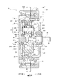
図1は、本発明の一実施形態に係る差動型遊星減速機1の縦断面図である。この差動型遊星減速機1は、入力部材10に入力される第1回転数の回転運動を、第1回転数よりも低い第2回転数の回転運動に減速して出力する装置である。差動型遊星減速機1は、例えば、ロボットの関節に、電動機とともに組み込まれて使用される。ただし、差動型遊星減速機1は、アシストスーツ、無人搬送台車などの他の装置に用いられるものであってもよい。
<1. Configuration of Differential Planetary Reducer>
FIG. 1 is a longitudinal sectional view of a differential
図1に示すように、本実施形態の差動型遊星減速機1は、入力部材10、減速機構20、筐体30、出力部材40、一対の入力側軸受51、第1外側軸受521、第2外側軸受522、第1内側軸受53、および第2内側軸受54を備える。
As shown in FIG. 1, the differential
入力部材10は、中心軸91を中心として、減速前の第1回転数で回転する部材である。本実施形態の入力部材10は、軸方向に延びる柱状の入力シャフトである。入力部材10は、ギア、ベルト、カップリング等の動力伝達機構を介して、電動機の出力軸に接続される。電動機を駆動させると、電動機から供給される駆動力により、入力部材10が、中心軸91を中心として、第1回転数で回転する。
The
減速機構20は、入力部材10の回転運動を、第1回転数よりも低い第2回転数の回転運動に変換して、出力部材40へ伝達する機構である。図2は、図1のA-A位置から見た減速機構20の横断面図である。図2では、図面の煩雑化を避けるため、断面を示すハッチングと、各ギアの歯の図示とが、省略されている。
The
図1および図2に示すように、減速機構20は、太陽歯車21、複数の遊星歯車22、固定内歯歯車23、回転内歯歯車24、およびキャリア25を有する。
As shown in FIGS. 1 and 2 , the
太陽歯車21は、入力部材10とともに、中心軸91を中心として、第1回転数で回転する歯車である。太陽歯車21は、外周面に複数の太陽外歯211を有する。複数の太陽外歯211は、中心軸91を中心として、一定の角度ピッチで設けられている。各太陽外歯211は、太陽歯車21の外周面において、径方向外側へ突出する。
The
本実施形態では、入力部材10と太陽歯車21とが、単一の部材により形成されている。換言すれば、入力部材10が太陽歯車21を有する。しかしながら、入力部材10と太陽歯車21とは、別部材であってもよい。その場合、入力部材10に対して太陽歯車21が、相対回転不能な状態に固定されていればよい。
In this embodiment, the
遊星歯車22は、太陽歯車21の径方向外側に配置された歯車である。図2に示すように、本実施形態では、太陽歯車21の周りに、3つの遊星歯車22が、周方向に等間隔で配置されている。ただし、減速機構20が有する遊星歯車22の数は、1~2つであってもよく、4つ以上であってもよい。
The
各遊星歯車22は、中央に貫通孔220を有する。貫通孔220は、遊星歯車22を軸方向に貫通する。貫通孔220には、後述するキャリアピン254が挿入される。また、遊星歯車22の内周面と、キャリアピン254との間には、一対の遊星軸受225が介在する。これにより、遊星歯車22は、中心軸91と平行な遊星軸92を中心として、回転可能に支持される。
Each
図1に示すように、遊星歯車22は、第1歯車221と、第1歯車221よりも小径の第2歯車222とを有する。第1歯車221は、第2歯車222よりも、軸方向一方側に位置する。本実施形態では、第1歯車221および第2歯車222が、単一の部材により形成されている。ただし、第1歯車221および第2歯車222は、別部材であってもよい。その場合、第1歯車221と第2歯車222が、相対回転不能な状態に固定されていればよい。
As shown in FIG. 1 , the
第1歯車221は、外周面に複数の第1外歯223を有する。複数の第1外歯223は、遊星軸92を中心として、一定の角度ピッチで設けられている。各第1外歯223は、第1歯車221の外周面において、遊星軸92から離れる向きに突出する。太陽歯車21の太陽外歯211と、第1歯車221の第1外歯223とは、互いに噛み合う。第1歯車221は、太陽歯車21と噛み合いながら、遊星軸92を中心として自転する。
The
第2歯車222は、第1歯車221とともに、遊星軸92を中心として自転する。第2歯車222の遊星軸92を中心とする径は、第1歯車221の遊星軸92を中心とする径よりも、小さい。第2歯車222は、外周面に複数の第2外歯224を有する。複数の第2外歯224は、遊星軸92を中心として、一定の角度ピッチで設けられている。各第2外歯224は、第2歯車222の外周面において、遊星軸92から離れる向きに突出する。第1歯車221が有する第1外歯223の数と、第2歯車222が有する第2外歯224の数とは、相違する。
The
固定内歯歯車23は、中心軸91を中心とする円環状の歯車である。固定内歯歯車23は、複数の遊星歯車22の第1歯車221の径方向外側に位置する。固定内歯歯車23と筐体30とは、第1ボルト61により、互いに固定される。このため、固定内歯歯車23は、筐体30に対して常に静止した状態に保たれる。なお、固定内歯歯車23および筐体30は、単一の部材により形成されていてもよい。
The fixed
固定内歯歯車23は、複数の第1内歯231を有する。複数の第1内歯231は、中心軸91を中心として、一定の角度ピッチで設けられている。各第1内歯231は、固定内歯歯車23の内周面において、径方向内側へ突出する。上述した第1歯車221の第1外歯223は、固定内歯歯車23の第1内歯231と噛み合う。
The fixed
回転内歯歯車24は、中心軸91を中心とする円環状の歯車である。回転内歯歯車24は、固定内歯歯車23よりも、軸方向他方側に位置する。回転内歯歯車24の中心軸91を中心とする内径は、固定内歯歯車23の中心軸91を中心とする内径よりも、小さい。回転内歯歯車24は、複数の遊星歯車22の第2歯車222の径方向外側に位置する。回転内歯歯車24と出力部材40とは、第2ボルト62により、互いに固定される。なお、回転内歯歯車24および出力部材40は、単一の部材により形成されていてもよい。
The rotating
回転内歯歯車24は、複数の第2内歯241を有する。複数の第2内歯241は、中心軸91を中心として、一定の角度ピッチで設けられている。各第2内歯241は、回転内歯歯車24の内周面において、径方向内側へ突出する。上述した第2歯車222の第2外歯224は、回転内歯歯車24の第2内歯241と噛み合う。固定内歯歯車23が有する第1内歯231の数と、回転内歯歯車24が有する第2内歯241の数とは、相違する。
The rotary
キャリア25は、複数の遊星歯車22を、遊星軸92を中心として自転しつつ、中心軸91を中心として公転することが可能な状態に支持するユニットである。図1および図2に示すように、キャリア25は、籠型のキャリア部材250と、複数のキャリアピン254とを有する。
The
キャリア部材250は、第1円板部251、第2円板部252、および複数の接続部253を有する。第1円板部251は、複数の遊星歯車22の軸方向一方側に位置する。第2円板部252は、複数の遊星歯車22の軸方向他方側に位置する。第1円板部251および第2円板部252は、それぞれ、中心軸91に対して直交する方向に広がる。複数の接続部253は、第1円板部251と第2円板部252とを、軸方向に接続する。遊星歯車22は、第1円板部251と第2円板部252との軸方向間、かつ、隣り合う接続部253の周方向間に配置される。
The
キャリアピン254は、遊星軸92に沿って軸方向に延びる、円柱状の部材である。キャリアピン254の軸方向一方側の端部は、第1円板部251に固定される。キャリアピン254の軸方向他方側の端部は、第2円板部252に固定される。複数のキャリアピン254は、中心軸91を中心として、周方向に等間隔に配置される。遊星歯車22の内周面と、キャリアピン254との間には、一対の遊星軸受225が介在する。これにより、遊星歯車22が、遊星軸92を中心として回転可能に支持される。
また、キャリア25は、後述する第1内側軸受53および第2内側軸受54により、中心軸91を中心として回転可能に支持される。遊星歯車22は、遊星軸92を中心として自転しながら、キャリア25とともに、中心軸91を中心として公転できる。
Further, the
筐体30は、減速機構20を内部に収容する略カップ状の部材である。筐体30は、差動型遊星減速機1が搭載される装置の枠体に固定される。筐体30は、略平板状の筐体ベース部31と、円筒状の筐体壁部32とを有する。筐体ベース部31の少なくとも一部は、減速機構20よりも軸方向一方側に位置する。筐体ベース部31は、中心軸91に対して直交する方向に広がる。ただし、上記の「直交する方向」は、「略直交する方向」も含む。筐体壁部32は、減速機構20よりも径方向外側に位置する。筐体壁部32は、筐体ベース部31の外周部(径方向外縁)から、軸方向他方側へ向けて延びる。
The
なお、筐体30は、必ずしも減速機構20の全体を内部に収容していなくてもよい。例えば、遊星歯車22の一部分が、筐体30の内部に配置され、遊星歯車22の他の部分が、筐体30の外部に配置されていてもよい。
Note that the
筐体ベース部31と入力部材10との間の径方向の隙間には、一対の入力側軸受51が介在する。入力側軸受51には、例えば、ボールベアリングが用いられる。入力側軸受51の内輪は、入力部材10の外周面に固定される。入力側軸受51の外輪は、筐体ベース部31の内周面に固定される。これにより、入力部材10が、筐体30に対して回転可能に支持される。なお、入力側軸受51は、ボールベアリング以外の軸受であってもよい。
A pair of input-
出力部材40は、中心軸91を中心として、減速後の第2回転数で回転する部材である。出力部材40は、差動型遊星減速機1が搭載される装置の、駆動対象となる部品に固定される。出力部材40は、略平板状の出力ベース部41と、円筒状の出力壁部42とを有する。出力ベース部41の少なくとも一部は、減速機構20よりも軸方向他方側に位置する。出力ベース部41は、中心軸91に対して直交する方向に広がる。ただし、上記の「直交する方向」は、「略直交する方向」も含む。出力壁部42は、減速機構20よりも径方向外側に位置する。出力壁部42は、出力ベース部41の外周部(径方向外縁)から、軸方向一方側へ向けて延びる。
The
出力壁部42は、筐体壁部32の径方向内側に挿入される。すなわち、出力壁部42は、筐体壁部32の径方向内側に位置する。このように、筐体壁部32と出力壁部42とを、径方向に重なるように配置すれば、筐体30および出力部材40を、全体として軸方向に小型化できる。したがって、差動型遊星減速機1を、軸方向に薄型化できる。
The
筐体壁部32の内周面と出力壁部42の外周面との間の径方向の隙間には、第1外側軸受521および第2外側軸受522が介在する。第2外側軸受522は、第1外側軸受521よりも、軸方向他方側に位置する。第1外側軸受521および第2外側軸受522には、例えば、ボールベアリングが用いられる。第1外側軸受521の外輪および第2外側軸受522の外輪は、筐体壁部32の内周面に固定される。第1外側軸受521の内輪および第2外側軸受522の内輪は、出力壁部42の外周面に固定される。筐体壁部32は、第1外側軸受521および第2外側軸受522を介して、出力壁部42を、回転可能に支持する。これにより、出力部材40が、筐体30に対して回転可能に支持される。なお、第1外側軸受521および第2外側軸受522は、ボールベアリング以外の軸受であってもよい。
A first
また、出力部材40は、凸部43を有する。凸部43は、出力ベース部41の中央(径方向中心)から、軸方向一方側へ向けて突出する。入力部材10および凸部43は、中心軸91に沿って、同軸に配置される。出力壁部42は、凸部43よりも径方向外側に位置する。
Moreover, the
凸部43の軸方向一方側の端部は、遊星歯車22の第2歯車222の径方向内側に位置する。遊星歯車22の第2歯車222は、第1歯車221よりも小径である。このため、第2歯車222の径方向内側には、空間が存在する。凸部43の軸方向一方側の端部は、当該空間に配置される。このようにすれば、遊星歯車22と出力部材40とを、軸方向に接近させることができる。したがって、差動型遊星減速機1の軸方向の寸法を、より低減できる。
One axial end of the
図1に示すように、凸部43は、支持面431および円錐部432を有する。支持面431は、軸方向に延びる円筒状の面である。後述する第2内側軸受54は、支持面431に支持される。円錐部432は、支持面431よりも軸方向一方側に位置する。円錐部432は、軸方向一方側ヘ向かうにつれて、徐々に縮径する。
As shown in FIG. 1, the
入力部材10とキャリア部材250との間の径方向の隙間には、第1内側軸受53が介在する。第1内側軸受53は、遊星歯車22よりも、軸方向一方側に位置する。第1内側軸受53は、入力部材10の外周面と、キャリア部材250の第1円板部251の内周面との間に介在する。
A first
第1内側軸受53には、例えば、ボールベアリングが用いられる。第1内側軸受53の内輪は、入力部材10の外周面に固定される。第1内側軸受53の外輪は、キャリア部材250の第1円板部251の内周面に固定される。入力部材10は、第1内側軸受53を介して、キャリア部材250の第1円板部251を支持する。これにより、入力部材10とキャリア25とが、中心軸91を中心として、互いに異なる回転数で回転可能となる。なお、第1内側軸受53は、ボールベアリング以外の軸受であってもよい。
A ball bearing, for example, is used for the first
図1に示すように、入力部材10は、入力側鍔部11を有する。入力側鍔部11は、入力部材10の外周面から、径方向外側へ突出する。入力側鍔部11は、第1内側軸受53の内輪の軸方向一方側の端面と、軸方向に接触する。これにより、入力部材10に対して第1内側軸受53が、軸方向一方側へずれることが抑制される。
As shown in FIG. 1 , the
また、第1内側軸受53の外輪は、第1鍔部531を有する。第1鍔部531は、第1内側軸受53の外輪の外周面から、径方向外側へ突出する。第1鍔部531は、キャリア部材250の第1円板部251の軸方向一方側の面と、軸方向に接触する。これにより、キャリア25に対して第1内側軸受53が、軸方向他方側へずれることが抑制される。また、第1内側軸受53に対してキャリア25が、軸方向一方側へずれることが抑制される。
Also, the outer ring of the first
また、第1円板部251と第1内側軸受53とは、中心軸91に対して直交する第1平面上に位置する。このように、第1円板部251と第1内側軸受53とを、径方向に重なるように配置すれば、第1円板部251および第1内側軸受53の全体としての軸方向の寸法を低減できる。したがって、差動型遊星減速機1を、軸方向により薄型化できる。
Also, the
出力部材40の凸部43とキャリア部材250との間の径方向の隙間には、第2内側軸受54が介在する。第2内側軸受54は、遊星歯車22よりも、軸方向他方側に位置する。第2内側軸受54は、凸部43の支持面431と、キャリア部材250の第2円板部252の内周面との間に介在する。
A second
第2内側軸受54には、例えば、ボールベアリングが用いられる。第2内側軸受54の内輪は、凸部43の支持面431に固定される。第2内側軸受54の外輪は、キャリア部材250の第2円板部252の内周面に固定される。凸部43は、第2内側軸受54を介して、キャリア部材250の第2円板部252を支持する。これにより、出力部材40とキャリア25とが、中心軸91を中心として、互いに異なる回転数で回転可能となる。なお、第2内側軸受54は、ボールベアリング以外の軸受であってもよい。
A ball bearing, for example, is used for the second
図1に示すように、出力部材40は、出力側鍔部44を有する。出力側鍔部44は、凸部43の支持面431から、径方向外側へ突出する。出力側鍔部44は、第2内側軸受54の内輪の軸方向他方側の端面と、軸方向に接触する。これにより、出力部材40に対して第2内側軸受54が、軸方向他方側へずれることが抑制される。
As shown in FIG. 1 , the
また、第2内側軸受54の外輪は、第2鍔部541を有する。第2鍔部541は、第2内側軸受54の外輪の外周面から、径方向外側へ突出する。第2鍔部541は、キャリア部材250の第2円板部252の軸方向他方側の面と、軸方向に接触する。これにより、キャリア25に対して第2内側軸受54が、軸方向一方側へずれることが抑制される。また、第2内側軸受54に対してキャリア25が、軸方向他方側へずれることが抑制される。
Also, the outer ring of the second
また、第2円板部252と第2内側軸受54とは、中心軸91に対して直交する第2平面上に位置する。このように、第2円板部252と第2内側軸受54とを、径方向に重なるように配置すれば、第2円板部252および第2内側軸受54の全体としての軸方向の寸法を低減できる。したがって、差動型遊星減速機1を、軸方向により薄型化できる。
Also, the
このような差動型遊星減速機1において、入力部材10および太陽歯車21が第1回転数で回転すると、遊星歯車22は、太陽歯車21との噛み合いにより、遊星軸92を中心として自転する。また、遊星歯車22は、太陽歯車21および固定内歯歯車23と噛み合っているため、遊星軸92を中心として自転しながら、固定内歯歯車23に沿って、太陽歯車21の周りを周方向に公転する。すなわち、複数の遊星歯車22は、遊星軸92を中心として自転しながら、中心軸91を中心として公転する。このとき、中心軸91を中心とする遊星歯車22の公転の回転数は、第1回転数よりも低い中間回転数となる。
In such a differential
また、固定内歯歯車23が有する第1内歯231の数に対する第1歯車221が有する第1外歯223の数の比と、回転内歯歯車24が有する第2内歯241の数に対する第2歯車222が有する第2外歯224の数の比と、は相違する。このため、遊星歯車22の公転に伴い、固定内歯歯車23に対して回転内歯歯車24が、歯数の差に応じた回転数で回転する。この回転内歯歯車24の回転数は、中間回転数よりもさらに低い第2回転数となる。その結果、回転内歯歯車24および出力部材40が、中心軸91を中心として第2回転数で回転する。したがって、出力部材40から、減速後の第2回転数の回転運動を取り出すことができる。
Also, the ratio of the number of first
上述の通り、この差動型遊星減速機1は、入力部材10が、第1内側軸受53を介して、キャリア25を支持する。また、出力部材40の凸部43が、第2内側軸受54を介して、キャリア25を支持する。すなわち、入力部材10と出力部材40の2部材により、キャリア25が支持される。これにより、キャリア25を安定した姿勢で支持できる。そして、キャリア25の姿勢が安定すれば、遊星歯車22の自転および公転の姿勢も、安定させることができる。
As described above, in this differential
特に、本実施形態の差動型遊星減速機1では、太陽歯車21の中心軸91を中心とする径が、第2歯車222の遊星軸92を中心とする径よりも、小さい。このように、太陽歯車21の径を小さくすれば、差動型遊星減速機1の減速比を大きくすることができる。ただし、太陽歯車21の径を小さくすると、太陽歯車21に対してキャリア25を安定的に支持することが難しくなり、軸方向の薄型化も困難になる。しかしながら、本実施形態の構造では、入力部材10と出力部材40の2部材で、キャリア25を支持する。これにより、キャリア25を、より安定的に支持できる。
In particular, in the differential
また、本実施形態では、第1外側軸受521と第2外側軸受522とが、軸方向に間隔をあけて配置される。これにより、筐体30に対して出力部材40を、安定した姿勢で支持できる。その結果、出力部材40に支持されるキャリア25の姿勢も、さらに安定させることができる。
Further, in the present embodiment, the first
<2.差動型遊星減速機の製造方法>
図3は、差動型遊星減速機1の製造時の様子を示した図である。
<2. Manufacturing Method of Differential Planetary Reducer>
3A and 3B are diagrams showing the manufacturing state of the differential
図3に示すように、差動型遊星減速機1の製造時には、まず、筐体30に対して、入力部材10と、減速機構20のうち回転内歯歯車24以外の部分とを、組み付ける。これにより、入力部材10、太陽歯車21、複数の遊星歯車22、固定内歯歯車23、キャリア25、筐体30、入力側軸受51、第1内側軸受53、および第2内側軸受54を含む第1ユニットU1の準備ができる。
As shown in FIG. 3 , when manufacturing the differential
また、出力部材40に対して、回転内歯歯車24を固定し、第1外側軸受521および第2外側軸受522を組み付ける。これにより、回転内歯歯車24、出力部材40、第1外側軸受521、および第2外側軸受522を含む第2ユニットU2の準備ができる。
Also, the rotary
そして、図3中の白抜き矢印のように、第1ユニットU1の軸方向他方側から、第2ユニットU2を、軸方向一方側へ接近させる。そして、筐体壁部32の内側に、第2ユニットU2を挿入する。これにより、第1ユニットU1に対して第2ユニットU2を組み付ける。その後、筐体壁部32の内周面に設けられた溝33に、止め輪34を取り付ける。これにより、第1ユニットU1から第2ユニットU2が抜けることを防止する。
3, the second unit U2 is brought closer to the one axial side from the other axial side of the first unit U1. Then, the second unit U2 is inserted inside the
第1ユニットU1に対して第2ユニットU2を組み付ける際、出力部材40の凸部43は、第2内側軸受54の径方向内側に挿入される。このとき、凸部43の軸方向一方側の端部が円錐部432となっているため、第2内側軸受54の径方向内側に、凸部43を容易に挿入できる。また、第2内側軸受54の内輪に、円錐部432の外周面を接触させつつ挿入することにより、凸部43の中心が中心軸91と一致するように、第1ユニットU1に対して第2ユニットU2を、徐々に位置決めできる。詳しくは、第1内側軸受53の回転軸と第2内側軸受54の回転軸を結ぶ直線が、中心軸91に対して傾斜していても、円錐面432の案内によって、これを同軸上に修正することが可能となる。挿入後の円錐部432は、図1に示すように、第2歯車222の径方向内側に位置する。
When assembling the second unit U2 to the first unit U1, the
なお、図3の例では、回転内歯歯車24が、第2ユニットU2に属している。しかしながら、回転内歯歯車24は、第1ユニットU1に属するようにしてもよい。その場合、第1ユニットU1に対して第2ユニットU2を組み付けた後、第2ボルト62により、出力部材40に回転内歯歯車24を固定すればよい。この場合、回転内歯歯車24の外周面が出力壁部42の内周面に挿入される。出力壁部42の内周面の軸方向一方側に軸方向他方側に向けて縮径するテーパ面421を設けることで、回転内歯歯車24に対する出力壁部42の挿入が容易になる。
In addition, in the example of FIG. 3, the rotary
<3.変形例>
以上、本発明の一実施形態について説明したが、本発明は、上記の実施形態には限定されない。以下では、種々の変形例について、上記の実施形態との相違点を中心に説明する。なお、上記の実施形態と同等の部分については、重複説明を省略する。
<3. Variation>
Although one embodiment of the present invention has been described above, the present invention is not limited to the above embodiment. Various modifications will be described below, focusing on differences from the above-described embodiment. It should be noted that redundant description of parts equivalent to those of the above-described embodiment will be omitted.
<3-1.第1変形例>
図4は、第1変形例に係る差動型遊星減速機1の縦断面図である。図4の差動型遊星減速機1は、例えば、無人搬送台車の車輪に組み込まれて使用される。図4の例では、差動型遊星減速機1の軸方向一方側に、電動機70が直結されている。そして、電動機70の出力シャフトが、差動型遊星減速機1の入力部材10となっている。このようにすれば、電動機70の出力シャフトと、差動型遊星減速機1の入力部材10とを、別部品とする場合と比べて、部品点数を低減できる。また、電動機70および差動型遊星減速機1を、全体として軸方向に小型化できる。
<3-1. First modification>
FIG. 4 is a longitudinal sectional view of a differential
また、図4の例では、筐体壁部32が、出力壁部42の径方向内側に挿入される。すなわち、筐体壁部32が、出力壁部42の径方向内側に位置する。第1外側軸受521および第2外側軸受522は、筐体壁部32の外周面と、出力壁部42の内周面と、の間に介在する。このような配置でも、筐体壁部32と出力壁部42とを、径方向に重なるように配置することで、筐体30および出力部材40を、全体として軸方向に小型化できる。したがって、差動型遊星減速機1を、軸方向に薄型化できる。
Further, in the example of FIG. 4 , the
また、図4の差動型遊星減速機1は、円環状のタイヤ80をさらに備える。タイヤ80は、出力壁部42の外周面に固定される。タイヤ80は、例えばゴム製である。このようにすれば、タイヤ80の径方向内側に、減速機構20が配置される。これにより、タイヤ80を回転させるための機構を、軸方向に薄型化できる。なお、差動型遊星減速機1は、出力壁部42とタイヤ80との間に、ホイールをさらに備えていてもよい。
Further, the differential
<3-2.第2変形例>
図5は、第2変形例に係る差動型遊星減速機1の縦断面図である。図5の差動型遊星減速機1では、入力部材10が軸継手となっている。電動機の出力シャフトは、入力部材10としての軸継手に、直接接続することができる。このようにすれば、電動機の出力シャフトと、差動型遊星減速機1の入力部材10との間に、他の部品を介在させる場合と比べて、電動機および差動型遊星減速機1を、全体として軸方向に小型化できる。
<3-2. Second modification>
FIG. 5 is a longitudinal sectional view of a differential
上述した実施形態では、差動型遊星減速機1が、第1外側軸受521および第2外側軸受522を備えていた。これに対し、図5の差動型遊星減速機1は、1つの外側軸受52を備える。外側軸受52は、筐体壁部32の内周面と、出力壁部42の外周面との間の径方向の隙間に介在する。
In the embodiment described above, the differential
図5の外側軸受52は、クロスローラベアリングである。クロスローラベアリングは、外輪と内輪との間に、複数のローラを有する。複数のローラは、外輪の内周面に設けられたV字状の溝と、内輪の外周面に設けられたV字状の溝との間に、向きを交互に変えながら配置される。このようなクロスローラベアリングは、ボールベアリングのように一対で用いずとも、1つで必要な剛性を得ることができる。したがって、外側軸受52の数を減らしつつ、筐体30に対して出力部材40を、安定して支持することができる。
The
図5のキャリア25は、複数の遊星歯車22を、遊星軸92を中心として自転しつつ、中心軸91を中心として公転することが可能な状態に支持するユニットである。キャリア25は、キャリア部材250と、複数のキャリアピン254とを有する。
The
キャリア部材250は、第1円板部251および第2円板部252を有する。本実施形態のキャリア部材250は、接続部253を有していない。第1円板部251と第2円板部252は、別部材である。第1円板部251は、複数の遊星歯車22の軸方向一方側に位置する。第2円板部252は、複数の遊星歯車22の軸方向他方側に位置する。第1円板部251および第2円板部252は、それぞれ、中心軸91に対して直交する方向に広がる。遊星歯車22は、第1円板部251と第2円板部252との軸方向間に配置される。
キャリアピン254は、遊星軸92に沿って軸方向に延びる、円柱状の部材である。キャリアピン254の軸方向一方側の端部は、第1円板部251に固定される。複数のキャリアピン254それぞれの軸方向他方側の外周部は、第2円板部252の外周部に接触する。複数のキャリアピン254は、中心軸91を中心として、周方向に等間隔に配置される。遊星歯車22の内周面と、キャリアピン254との間には、一対の遊星軸受225が介在する。これにより、遊星歯車22が、遊星軸92を中心として回転可能に支持される。
図5の例では、キャリアピン254および第1円板部251で遊星歯車22を支持し、キャリア25は第1内側軸受53で入力部材10に支持される。しかし、第1内側軸受53のみで中心軸91に対して遊星軸92を平行に保持することは難しいので、第2円板部252の外周面でキャリアピン254の径方向変位を阻止することで、遊星軸92は安定して回転することができる。
In the example of FIG. 5 , the
また、図5の例では、キャリア部材250の第1円板部251が、第3鍔部255を有する。第3鍔部255は、第1円板部251の内周面から、径方向内側へ突出する。第3鍔部255は、第1内側軸受53の外輪の軸方向他方側の端面と、軸方向に接触する。これにより、キャリア25に対して第1内側軸受53が、軸方向他方側へずれることが抑制される。また、第1内側軸受53に対してキャリア25が、軸方向一方側へずれることが抑制される。
Also, in the example of FIG. 5 , the
また、図5の例では、キャリア部材250の第2円板部252が、第4鍔部256を有する。第4鍔部256は、第2円板部252の内周面から、径方向内側へ突出する。第4鍔部256は、第2内側軸受54の外輪の軸方向一方側の端面と、軸方向に接触する。これにより、キャリア25に対して第2内側軸受54が、軸方向一方側へずれることが抑制される。また、第2内側軸受54に対してキャリア25が、軸方向他方側へずれることが抑制される。
5, the
また、図5の例では、軸方向他方側に位置する遊星軸受225の内輪の軸方向他方側端面と第2円板部252の軸方向一方側端面の間に止め輪またはカラーが挿入されている。これにより、第1円板部251と第2円板部252との互いの接近が抑止されることでキャリア25が形成される。したがって、第1内側軸受53に対して第2内側軸受54が、軸方向一方側へずれることが抑制される。また、第2内側軸受54に対して第1内側軸受53が、軸方向他方側へずれることが抑制される。
In the example of FIG. 5, a snap ring or a collar is inserted between the other axial end surface of the inner ring of the
<3-3.その他>
上記の実施形態では、入力部材10が、第1内側軸受53を介して、キャリア25を支持し、かつ、出力部材40の凸部43が、第2内側軸受54を介して、キャリア25を支持していた。すなわち、上記の実施形態では、入力部材10と出力部材40の2部材により、キャリア25を支持していた。しかしながら、入力部材10および出力部材40のうち、出力部材40のみで、キャリア25を支持してもよい。その場合でも、出力部材40に設けられた凸部43によりキャリア25を支持することで、キャリア25の姿勢を安定させることができる。
<3-3. Others>
In the above embodiment, the
差動型遊星減速機の細部の形状については、本願の各図に示された形状と異なっていてもよい。また、上記の実施形態または変形例に登場した各要素を、矛盾が生じない範囲で、適宜に取捨選択してもよい。 The shape of the details of the differential planetary speed reducer may differ from the shapes shown in the drawings of this application. Moreover, each element appearing in the above embodiments or modifications may be appropriately selected within a range that does not cause contradiction.
<4.ロボット>
図6は、差動型遊星減速機1を備えたロボット100の概要図である。ロボット100は、例えば、工業製品の製造ラインにおいて、部品の搬送、加工、組立等の作業を行う、いわゆる産業用ロボットである。図6に示すように、ロボット100は、ベースフレーム101、アーム102、差動型遊星減速機1、および電動機70を有する。差動型遊星減速機1および電動機70は、ベースフレーム101とアーム102との間の関節部に組み込まれる。これにより、キャリア25を安定した姿勢で支持できる差動型遊星減速機20を備えたロボット100を実現できる。
<4. Robot>
FIG. 6 is a schematic diagram of a
ベースフレーム101は、差動型遊星減速機1の筐体30および電動機70のケーシングのいずれかに固定される。電動機70の出力シャフトは、差動型遊星減速機1の入力部材10に固定される。アーム102は、差動型遊星減速機1の出力部材40に固定される。電動機70を駆動させると、電動機70の出力シャフトとともに、入力部材10が、第1回転数で回転する。そして、出力部材40とともに、アーム102が、第2回転数で回転する。
The
本発明は、差動型遊星減速機およびロボットに利用できる。 INDUSTRIAL APPLICABILITY The present invention can be used for differential planetary reduction gears and robots.
1 差動型遊星減速機
10 入力部材
11 入力側鍔部
20 減速機構
21 太陽歯車
22 遊星歯車
23 固定内歯歯車
24 回転内歯歯車
25 キャリア
30 筐体
31 筐体ベース部
32 筐体壁部
40 出力部材
41 出力ベース部
42 出力壁部
43 凸部
44 出力側鍔部
51 入力側軸受
52 外側軸受
53 第1内側軸受
54 第2内側軸受
91 中心軸
92 遊星軸
100 ロボット
221 第1歯車
222 第2歯車
250 キャリア部材
251 第1円板部
252 第2円板部
253 接続部
254 キャリアピン
255 第3鍔部
256 第4鍔部
431 支持面
432 円錐部
521 第1外側軸受
522 第2外側軸受
531 第1鍔部
541 第2鍔部
U1 第1ユニット
U2 第2ユニット
Claims (22)
前記入力部材の回転運動を、前記第1回転数よりも低い第2回転数の回転運動に変換する減速機構と、
前記減速機構を収容する筐体と、
前記中心軸を中心として前記第2回転数で回転する出力部材と、
を備え、
前記減速機構は、
前記入力部材とともに、前記中心軸を中心として前記第1回転数で回転する太陽歯車と、
前記太陽歯車と噛み合いながら、前記中心軸と平行な遊星軸を中心として自転する第1歯車と、前記第1歯車とともに前記遊星軸を中心として自転する第2歯車と、を有する遊星歯車と、
前記筐体に固定され、前記第1歯車と噛み合う円環状の固定内歯歯車と、
前記出力部材に固定され、前記第2歯車と噛み合う円環状の回転内歯歯車と、
前記遊星歯車を、前記遊星軸を中心として自転しつつ、前記中心軸を中心として公転することが可能な状態に支持するキャリアと、
を有し、
前記筐体は、
前記減速機構よりも軸方向一方側に位置する筐体ベース部と、
前記筐体ベース部の外周部から軸方向他方側へ延びる円筒状の筐体壁部と、
を有し、
前記出力部材は、
前記減速機構よりも軸方向他方側に位置する出力ベース部と、
前記出力ベース部の外周部から軸方向一方側へ延びる円筒状の出力壁部と、
前記出力ベース部の中央から軸方向一方側へ延びる凸部と、
を有し、
前記筐体ベース部の内周面と前記入力部材との間に介在する入力側軸受と、
前記筐体壁部と前記出力壁部との間に介在する外側軸受と、
前記入力部材と前記キャリアとの間に介在する第1内側軸受と、
前記凸部と前記キャリアとの間に介在する第2内側軸受と、
をさらに備える、差動型遊星減速機。 an input member that rotates about a central axis at a first rotation speed;
a speed reduction mechanism that converts rotational motion of the input member into rotational motion at a second rotational speed lower than the first rotational speed;
a housing that houses the speed reduction mechanism;
an output member that rotates at the second rotation speed about the central axis;
with
The speed reduction mechanism is
a sun gear that rotates at the first rotation speed about the central axis together with the input member;
a planetary gear having a first gear that rotates about a planetary axis parallel to the central axis while meshing with the sun gear, and a second gear that rotates about the planetary axis together with the first gear;
an annular fixed internal gear fixed to the housing and meshing with the first gear;
an annular rotating internal gear fixed to the output member and meshing with the second gear;
a carrier that supports the planetary gear so that it can rotate about the planetary shaft and revolve about the central axis;
has
The housing is
a housing base located on one side in the axial direction of the speed reduction mechanism;
a cylindrical housing wall portion extending from the outer peripheral portion of the housing base portion to the other side in the axial direction;
has
The output member is
an output base located on the other side in the axial direction of the speed reduction mechanism;
a cylindrical output wall portion extending from the outer peripheral portion of the output base portion to one side in the axial direction;
a convex portion extending from the center of the output base portion to one side in the axial direction;
has
an input-side bearing interposed between the inner peripheral surface of the housing base portion and the input member;
an outer bearing interposed between the housing wall and the output wall;
a first inner bearing interposed between the input member and the carrier;
a second inner bearing interposed between the projection and the carrier;
A differential planetary reducer, further comprising:
前記第2歯車の前記遊星軸を中心とする径は、前記第1歯車の前記遊星軸を中心とする径よりも小さく、
前記太陽歯車の前記中心軸を中心とする径は、前記第2歯車の前記遊星軸を中心とする径よりも、さらに小さい、差動型遊星減速機。 The differential planetary reduction gear according to claim 1,
The diameter of the second gear centered on the planetary shaft is smaller than the diameter of the first gear centered on the planetary shaft,
A differential planetary reduction gear, wherein the diameter of the sun gear centered on the central axis is smaller than the diameter of the second gear centered on the planetary shaft.
前記キャリアは、
前記遊星歯車の軸方向一方側に位置する第1円板部と、
前記遊星歯車の軸方向他方側に位置する第2円板部と、
を有し、
前記第1内側軸受は、前記入力部材と前記第1円板部との間に介在し、
前記第2内側軸受は、前記凸部と前記第2円板部との間に介在する、差動型遊星減速機。 The differential planetary reduction gear according to claim 1 or claim 2,
The carrier is
a first disk portion positioned on one side in the axial direction of the planetary gear;
a second disk portion positioned on the other side in the axial direction of the planetary gear;
has
The first inner bearing is interposed between the input member and the first disk portion,
The second inner bearing is a differential planetary reduction gear interposed between the convex portion and the second disk portion.
前記第1円板部と、前記第1内側軸受とが、前記中心軸に対して直交する第1平面上に位置し、
前記第2円板部と、前記第2内側軸受とが、前記中心軸に対して直交する第2平面上に位置する、差動型遊星減速機。 A differential planetary reduction gear according to claim 3,
the first disk portion and the first inner bearing are positioned on a first plane perpendicular to the central axis;
A differential planetary reduction gear, wherein the second disk portion and the second inner bearing are positioned on a second plane orthogonal to the central axis.
前記第1円板部と前記第2円板部は、別部材であり、
前記キャリアは、
遊星軸に沿って軸方向に延びるキャリアピン
をさらに有し、
前記キャリアピンの軸方向一方側の端部は、前記第1円板部に固定され、
前記キャリアピンの軸方向他方側の外周部は、前記第2円板部の外周部に接触する、差動型遊星減速機。 The differential planetary reduction gear according to claim 3 or claim 4,
The first disk portion and the second disk portion are separate members,
The carrier is
further comprising a carrier pin extending axially along the planetary axis;
one end of the carrier pin in the axial direction is fixed to the first disc portion;
A differential planetary reduction gear, wherein an outer peripheral portion of the carrier pin on the other side in the axial direction is in contact with an outer peripheral portion of the second disk portion.
前記外側軸受は、
第1外側軸受と、
前記第1外側軸受よりも軸方向他方側に位置する第2外側軸受と、
を含む、差動型遊星減速機。 The differential planetary reduction gear according to any one of claims 1 to 5,
The outer bearing is
a first outer bearing;
a second outer bearing located on the other side in the axial direction of the first outer bearing;
A differential planetary reducer, including
前記外側軸受は、クロスローラベアリングである、差動型遊星減速機。 The differential planetary reduction gear according to any one of claims 1 to 5,
A differential planetary reduction gear, wherein the outer bearing is a cross roller bearing.
前記出力壁部は、前記筐体壁部の径方向内側に挿入され、
前記外側軸受は、前記筐体壁部の内周面と、前記出力壁部の外周面と、の間に介在する、差動型遊星減速機。 The differential planetary reduction gear according to any one of claims 1 to 7,
The output wall portion is inserted radially inward of the housing wall portion,
The outer bearing is a differential planetary reduction gear interposed between an inner peripheral surface of the housing wall portion and an outer peripheral surface of the output wall portion.
前記筐体壁部は、前記出力壁部の径方向内側に挿入され、
前記外側軸受は、前記筐体壁部の外周面と、前記出力壁部の内周面と、の間に介在する、差動型遊星減速機。 The differential planetary reduction gear according to any one of claims 1 to 7,
The housing wall is inserted radially inward of the output wall,
The outer bearing is a differential planetary reduction gear interposed between an outer peripheral surface of the housing wall portion and an inner peripheral surface of the output wall portion.
前記出力壁部の外周面に固定されたタイヤ
をさらに備える、差動型遊星減速機。 A differential planetary reduction gear according to claim 9,
A differential planetary reduction gear further comprising a tire fixed to an outer peripheral surface of the output wall.
前記凸部は、
前記第2内側軸受を支持する円筒状の支持面と、
前記支持面よりも軸方向一方側に位置し、軸方向一方側へ向かうにつれて縮径する円錐部と、
を有する、差動型遊星減速機。 The differential planetary reduction gear according to any one of claims 1 to 10,
The convex portion is
a cylindrical support surface supporting the second inner bearing;
a conical portion located on one side in the axial direction of the support surface and decreasing in diameter toward the one side in the axial direction;
A differential planetary reducer having a
前記凸部の軸方向一方側の端部が、前記第2歯車の径方向内側に位置する、差動型遊星減速機。 The differential planetary reduction gear according to any one of claims 1 to 11,
A differential planetary reduction gear, wherein one axial end of the convex portion is positioned radially inward of the second gear.
前記入力部材は、
前記第1内側軸受の内輪と軸方向に接触する入力側鍔部
を有し、
前記出力部材は、
前記第2内側軸受の内輪と軸方向に接触する出力側鍔部
を有する、差動型遊星減速機。 The differential planetary reduction gear according to any one of claims 1 to 12,
The input member is
having an input-side flange that axially contacts the inner ring of the first inner bearing;
The output member is
A differential planetary reduction gear having an output-side flange that axially contacts the inner ring of the second inner bearing.
前記第1内側軸受の外輪は、
前記キャリアと軸方向に接触する第1鍔部
を有し、
前記第2内側軸受の外輪は、
前記キャリアと軸方向に接触する第2鍔部
を有する、差動型遊星減速機。 The differential planetary reduction gear according to any one of claims 1 to 13,
The outer ring of the first inner bearing is
Having a first collar portion that is in axial contact with the carrier,
The outer ring of the second inner bearing,
A differential planetary reduction gear having a second collar portion axially contacting the carrier.
前記キャリアは、
前記第1内側軸受の外輪と軸方向に接触する第3鍔部と、
前記第2内側軸受の外輪と軸方向に接触する第4鍔部と、
を有する、差動型遊星減速機。 The differential planetary reduction gear according to any one of claims 1 to 13,
The carrier is
a third flange axially contacting the outer ring of the first inner bearing;
a fourth flange axially contacting the outer ring of the second inner bearing;
A differential planetary reducer having a
前記入力部材は、電動機の出力シャフトである、差動型遊星減速機。 A differential planetary reduction gear according to any one of claims 1 to 15,
A differential planetary reduction gear, wherein the input member is an output shaft of an electric motor.
前記入力部材は、電動機の出力シャフトに接続可能な軸継手である、差動型遊星減速機。 A differential planetary reduction gear according to any one of claims 1 to 15,
A differential planetary reduction gear, wherein the input member is a shaft coupling connectable to an output shaft of an electric motor.
前記入力部材は、入力シャフトである、差動型遊星減速機。 A differential planetary reduction gear according to any one of claims 1 to 15,
A differential planetary reduction gear, wherein the input member is an input shaft.
前記出力壁部の内周面は、軸方向一方側から軸方向他方側へ向かうにつれて縮径するテーパ面を有する、差動型遊星減速機。 A differential planetary reduction gear according to any one of claims 1 to 18,
The differential planetary reduction gear, wherein the inner peripheral surface of the output wall portion has a tapered surface whose diameter decreases from the one axial side toward the other axial side.
前記太陽歯車と噛み合い、前記中心軸と平行な遊星軸を中心として回転可能な遊星歯車と、
前記遊星歯車を前記遊星軸を中心として回転可能に支持するキャリアと、
少なくとも一部が前記遊星歯車よりも軸方向一方側に配置され、前記遊星歯車の少なくとも一部を収容する筐体と、
少なくとも一部が前記キャリアよりも軸方向他方側に配置され、前記遊星歯車と接続されて前記筐体と相対回転可能な出力部材と、
を有し、
前記出力部材は、
前記キャリアよりも軸方向他方側に配置され、前記中心軸と略直交する方向に広がる出力ベース部と、
前記出力ベース部から軸方向一方側に突出する凸部と、
を有し、
前記凸部は、内側軸受を介して前記キャリアを支持する、差動型遊星減速機。 an input member having a sun gear rotatable about a central axis;
a planetary gear meshing with the sun gear and rotatable about a planetary axis parallel to the central axis;
a carrier that supports the planetary gear rotatably around the planetary shaft;
a housing, at least a part of which is arranged on one side in the axial direction of the planetary gear and which houses at least a part of the planetary gear;
an output member at least partially arranged on the other side in the axial direction of the carrier, connected to the planetary gear and rotatable relative to the housing;
has
The output member is
an output base portion arranged on the other side of the carrier in the axial direction and extending in a direction substantially orthogonal to the central axis;
a convex portion protruding from the output base portion to one side in the axial direction;
has
A differential planetary reduction gear, wherein the projection supports the carrier via an inner bearing.
前記出力部材は、前記凸部よりも径方向外側に配置され、前記出力ベース部から軸方向一方側に突出する出力壁部を有し、
前記筐体は、
前記遊星歯車よりも軸方向一方側に配置され、前記中心軸と略直交する方向に広がる筐体ベース部と、
前記筐体ベース部の径方向外縁から軸方向他方側に突出する筐体壁部と、
を有し、
前記筐体壁部は、外側軸受を介して前記出力壁部を回転可能に支持する、差動型遊星減速機。 21. A differential planetary reduction gear according to claim 20,
the output member has an output wall portion disposed radially outwardly of the convex portion and protruding from the output base portion to one side in the axial direction;
The housing is
a housing base portion disposed on one axial side of the planetary gear and extending in a direction substantially orthogonal to the central axis;
a housing wall portion projecting from the radial outer edge of the housing base portion toward the other side in the axial direction;
has
The differential planetary reduction gear, wherein the housing wall rotatably supports the output wall via an outer bearing.
Priority Applications (2)
| Application Number | Priority Date | Filing Date | Title |
|---|---|---|---|
| JP2021110787A JP2023007745A (en) | 2021-07-02 | 2021-07-02 | Differential type planetary speed reducer and robot |
| CN202210765615.8A CN115560047A (en) | 2021-07-02 | 2022-07-01 | Differential type planetary reducer and robot |
Applications Claiming Priority (1)
| Application Number | Priority Date | Filing Date | Title |
|---|---|---|---|
| JP2021110787A JP2023007745A (en) | 2021-07-02 | 2021-07-02 | Differential type planetary speed reducer and robot |
Publications (1)
| Publication Number | Publication Date |
|---|---|
| JP2023007745A true JP2023007745A (en) | 2023-01-19 |
Family
ID=84737609
Family Applications (1)
| Application Number | Title | Priority Date | Filing Date |
|---|---|---|---|
| JP2021110787A Pending JP2023007745A (en) | 2021-07-02 | 2021-07-02 | Differential type planetary speed reducer and robot |
Country Status (2)
| Country | Link |
|---|---|
| JP (1) | JP2023007745A (en) |
| CN (1) | CN115560047A (en) |
Cited By (3)
| Publication number | Priority date | Publication date | Assignee | Title |
|---|---|---|---|---|
| CN118148928A (en) * | 2024-05-10 | 2024-06-07 | 大庆渝利机械制造有限公司 | Double-screw nondestructive slurry lifting pump |
| CN119704249A (en) * | 2024-12-31 | 2025-03-28 | 西北机器有限公司 | Collimation driving joint of reverse-mounted frameless torque motor combined with embedded speed reducing mechanism |
| WO2026140519A1 (en) * | 2024-12-26 | 2026-07-02 | 株式会社リケン | Planetary gear mechanism and planetary gear device comprising said planetary gear mechanism |
Citations (8)
| Publication number | Priority date | Publication date | Assignee | Title |
|---|---|---|---|---|
| FR2024273A1 (en) * | 1968-11-26 | 1970-08-28 | Lansing Bagnall Ltd | |
| JPS4920824A (en) * | 1972-06-20 | 1974-02-23 | ||
| JPS5554749A (en) * | 1978-10-02 | 1980-04-22 | Jonsson Sven | Planetary gear * its manufacture and its manufacturing device |
| JPS57184348U (en) * | 1981-05-20 | 1982-11-22 | ||
| JPH0674313A (en) * | 1992-06-30 | 1994-03-15 | Koyo Seiko Co Ltd | Planetary roller transmission and multistage structured planetary roller transmission |
| JPH11502286A (en) * | 1995-03-23 | 1999-02-23 | ツェットエフ、フリードリッヒスハーフェン、アクチエンゲゼルシャフト | Planetary gear type transmission |
| JP2003130146A (en) * | 2001-10-24 | 2003-05-08 | Seiko Epson Corp | Small speed reducer and geared motor equipped with the same |
| WO2018028204A1 (en) * | 2016-08-11 | 2018-02-15 | 谭国荣 | Pitch-circle differential speed-reduction device |
-
2021
- 2021-07-02 JP JP2021110787A patent/JP2023007745A/en active Pending
-
2022
- 2022-07-01 CN CN202210765615.8A patent/CN115560047A/en active Pending
Patent Citations (8)
| Publication number | Priority date | Publication date | Assignee | Title |
|---|---|---|---|---|
| FR2024273A1 (en) * | 1968-11-26 | 1970-08-28 | Lansing Bagnall Ltd | |
| JPS4920824A (en) * | 1972-06-20 | 1974-02-23 | ||
| JPS5554749A (en) * | 1978-10-02 | 1980-04-22 | Jonsson Sven | Planetary gear * its manufacture and its manufacturing device |
| JPS57184348U (en) * | 1981-05-20 | 1982-11-22 | ||
| JPH0674313A (en) * | 1992-06-30 | 1994-03-15 | Koyo Seiko Co Ltd | Planetary roller transmission and multistage structured planetary roller transmission |
| JPH11502286A (en) * | 1995-03-23 | 1999-02-23 | ツェットエフ、フリードリッヒスハーフェン、アクチエンゲゼルシャフト | Planetary gear type transmission |
| JP2003130146A (en) * | 2001-10-24 | 2003-05-08 | Seiko Epson Corp | Small speed reducer and geared motor equipped with the same |
| WO2018028204A1 (en) * | 2016-08-11 | 2018-02-15 | 谭国荣 | Pitch-circle differential speed-reduction device |
Cited By (3)
| Publication number | Priority date | Publication date | Assignee | Title |
|---|---|---|---|---|
| CN118148928A (en) * | 2024-05-10 | 2024-06-07 | 大庆渝利机械制造有限公司 | Double-screw nondestructive slurry lifting pump |
| WO2026140519A1 (en) * | 2024-12-26 | 2026-07-02 | 株式会社リケン | Planetary gear mechanism and planetary gear device comprising said planetary gear mechanism |
| CN119704249A (en) * | 2024-12-31 | 2025-03-28 | 西北机器有限公司 | Collimation driving joint of reverse-mounted frameless torque motor combined with embedded speed reducing mechanism |
Also Published As
| Publication number | Publication date |
|---|---|
| CN115560047A (en) | 2023-01-03 |
Similar Documents
| Publication | Publication Date | Title |
|---|---|---|
| US10281007B2 (en) | Speed reducer | |
| JP6767804B2 (en) | Gear transmission | |
| CN115560047A (en) | Differential type planetary reducer and robot | |
| KR20100097564A (en) | Fixed ring gear fixing device of planetary gear reducer | |
| US10112472B2 (en) | Drive device for hybrid vehicle | |
| CN105848945B (en) | For the driving device of hybrid vehicle | |
| JP7769305B2 (en) | Transmission mechanism | |
| CN213017530U (en) | Internal gearing transmission mechanism | |
| CN112112939B (en) | Transmission mechanism | |
| JP2017223246A (en) | Wave gear transmission | |
| CN102272479B (en) | micro traction drive | |
| JP7472599B2 (en) | Planetary reducer | |
| JP7367351B2 (en) | Multistage planetary roller power transmission device | |
| CN112145549A (en) | Rotating mechanism, speed reducer, and manufacturing method of rotating mechanism | |
| JP7376206B2 (en) | Planetary gears, planetary reducers, and planetary gear manufacturing methods | |
| JP7380979B2 (en) | Motorized transmission and trolley drive unit | |
| JP7787660B2 (en) | Harmonic gear device and robot | |
| JP6568749B2 (en) | Planetary roller type power transmission device | |
| KR100641651B1 (en) | Self-Centering Type Assembly Structure for Planetary Gear Reducer | |
| JP2016008652A (en) | Planetary roller traction drive device | |
| JP7399045B2 (en) | Gear motor, gear motor series | |
| WO2026004023A1 (en) | Planetary gear mechanism and power transmission unit | |
| JPS63235754A (en) | Planetary roller type power transmission | |
| CN120402582A (en) | reducer | |
| JP6713363B2 (en) | transmission |
Legal Events
| Date | Code | Title | Description |
|---|---|---|---|
| A621 | Written request for application examination |
Free format text: JAPANESE INTERMEDIATE CODE: A621 Effective date: 20240610 |
|
| RD03 | Notification of appointment of power of attorney |
Free format text: JAPANESE INTERMEDIATE CODE: A7423 Effective date: 20240610 |
|
| A977 | Report on retrieval |
Free format text: JAPANESE INTERMEDIATE CODE: A971007 Effective date: 20250116 |
|
| A131 | Notification of reasons for refusal |
Free format text: JAPANESE INTERMEDIATE CODE: A131 Effective date: 20250121 |
|
| A521 | Request for written amendment filed |
Free format text: JAPANESE INTERMEDIATE CODE: A523 Effective date: 20250324 |
|
| A02 | Decision of refusal |
Free format text: JAPANESE INTERMEDIATE CODE: A02 Effective date: 20250701 |