JP2023018564A - coin handling equipment - Google Patents

coin handling equipment Download PDF

Info

Publication number
JP2023018564A
JP2023018564A JP2021122778A JP2021122778A JP2023018564A JP 2023018564 A JP2023018564 A JP 2023018564A JP 2021122778 A JP2021122778 A JP 2021122778A JP 2021122778 A JP2021122778 A JP 2021122778A JP 2023018564 A JP2023018564 A JP 2023018564A
Authority
JP
Japan
Prior art keywords
coins
coin
counting
opening
sorting
Prior art date
Legal status (The legal status is an assumption and is not a legal conclusion. Google has not performed a legal analysis and makes no representation as to the accuracy of the status listed.)
Granted
Application number
JP2021122778A
Other languages
Japanese (ja)
Other versions
JP7565045B2 (en
Inventor
誠 林
Makoto Hayashi
保則 池本
Yasunori Ikemoto
隆宏 増田
Takahiro Masuda
Current Assignee (The listed assignees may be inaccurate. Google has not performed a legal analysis and makes no representation or warranty as to the accuracy of the list.)
Laurel Bank Machine Co Ltd
Laurel Precision Machines Co Ltd
Laurel Machinery Co Ltd
Original Assignee
Laurel Bank Machine Co Ltd
Laurel Precision Machines Co Ltd
Laurel Machinery Co Ltd
Priority date (The priority date is an assumption and is not a legal conclusion. Google has not performed a legal analysis and makes no representation as to the accuracy of the date listed.)
Filing date
Publication date
Application filed by Laurel Bank Machine Co Ltd, Laurel Precision Machines Co Ltd, Laurel Machinery Co Ltd filed Critical Laurel Bank Machine Co Ltd
Priority to JP2021122778A priority Critical patent/JP7565045B2/en
Publication of JP2023018564A publication Critical patent/JP2023018564A/en
Application granted granted Critical
Publication of JP7565045B2 publication Critical patent/JP7565045B2/en
Active legal-status Critical Current
Anticipated expiration legal-status Critical

Links

Images

Abstract

To provide a coin processor with improved security by having a sorting hole closed at the end of coin counting or at an abnormal stop.SOLUTION: A coin processor 1 includes: an identifying/counting unit 45 that identifies and counts coins fed into the coin processor; sorting holes 71a and 71b for separating the coins into at least two types by the identifying/counting unit 45 and dropping the coins of one type; opening/closing mechanisms 72a and 72b provided in the sorting holes 71a and 71b to open and close the sorting holes 71a and 71b; and a control unit 14 for performing control to open the sorting holes 71a and 71b by the opening/closing mechanisms 72a and 72b at the start of counting and to close the sorting holes 71a and 71b by the opening/closing mechanisms 72a and 72b at the end of counting.SELECTED DRAWING: Figure 3

Description

本発明は、硬貨処理装置に関する。 The present invention relates to a coin processing device.

現在、一般的なATM(Automatic Teller Machine)においては、小口(小数枚数)の硬貨の入出金が可能である。他方で、利用者によっては、大量の硬貨を入金する場合があり、ATMとは別に、硬貨処理装置を横付けして、大量の硬貨の入金を可能とする運用がなされている。 At present, a general ATM (Automatic Teller Machine) is capable of depositing and withdrawing small amounts (decimal number of coins). On the other hand, some users may deposit a large amount of coins, and a coin processing device is installed alongside the ATM to enable the deposit of a large amount of coins.

硬貨処理装置は、多種多様である。例えば、特許文献1に開示されている硬貨処理装置は、硬貨を金種別に小径順に選別して計数し、一時貯留した後、一時貯留した硬貨群を下方の金種別の収納箱に収納するものである。 Coin processors come in many varieties. For example, the coin processing apparatus disclosed in Patent Document 1 sorts coins by denomination in ascending order of diameter, counts them, temporarily stores them, and then stores the temporarily stored coins in storage boxes by denomination below. is.

特許文献2に開示されている硬貨処理装置は、硬貨を任意の種類別に選別することが可能な選別機構を多数備える。そして、最初の硬貨が第1の選別機構に到達するまでの間に識別計数された硬貨の中で最も枚数の多い金種の硬貨が第1の金種と自動的に設定される。そして、第1の選別機構で選別し、以下、第2の金種の硬貨を第2の選別機構で選別するようにしたものである。 The coin processing device disclosed in Patent Literature 2 includes a large number of sorting mechanisms capable of sorting coins according to arbitrary types. Then, the coin of the largest denomination among the coins discriminated and counted until the first coin reaches the first sorting mechanism is automatically set as the first denomination. Then, the coins are sorted by the first sorting mechanism, and then the coins of the second denomination are sorted by the second sorting mechanism.

特許文献3に開示されている硬貨処理装置は、硬貨を受け入れ可能か受入不可能かの二種に分け、受け入れ可能な硬貨については、さらに、金種混合状態で、複数の振分部の一つ一つに順に振り分けるようにしたものである。 The coin processing apparatus disclosed in Patent Document 3 divides coins into two types of acceptable coins and unacceptable coins, and further sorts the acceptable coins into one of a plurality of sorting units in a mixed denomination state. It is arranged to distribute them one by one in order.

特開昭55-092989号公報JP-A-55-092989 特開平04-293188号公報JP-A-04-293188 特許第4732121号公報Japanese Patent No. 4732121

しかしながら、いずれの特許文献に開示されている硬貨処理装置は、硬貨が、選別機構の選別孔で下方に落下し、一時貯留部又は収納部に収納されるものであって、少なくとも、搬送される硬貨通路最後(硬貨の搬送される方向において最下流)の選別孔は、単なる孔(穴)である。このため、例えば、硬貨通路の上方に張設される搬送ベルトを退避させると、外部に、選別孔を介して一時貯留部又は収納部が露出していることになる。 However, in the coin processing apparatuses disclosed in any of the patent documents, the coins fall downward through the sorting hole of the sorting mechanism and are stored in the temporary storage section or the storage section. The sorting hole at the end of the coin passage (the most downstream in the direction in which coins are conveyed) is simply a hole (hole). Therefore, for example, when the conveyor belt stretched above the coin passage is retracted, the temporary storage section or storage section is exposed to the outside through the sorting hole.

一般に硬貨処理装置にあっては、硬貨通路が設けられる硬貨計数機構部は、搬送ジャムなどの対応が容易に可能なように、上部カバーが開閉可能に設けられている。そのため、上部カバーを開放し、搬送ベルトを退避させることが行われる。そのためこの作業において、外部に、選別孔を介して一時貯留部又は収納部が露出すると、第三者が、選別孔から一時貯留部又は収納部に収納された硬貨を取り出し得ることができるようになる。また計数されていない硬貨が落下し、選別孔を介して一時貯留部又は収納部に収納されてしまうことがある。 Generally, in a coin processing apparatus, a coin counting mechanism provided with a coin passage is provided with an upper cover that can be opened and closed so as to easily deal with a transport jam or the like. Therefore, the upper cover is opened to retract the conveyor belt. Therefore, in this operation, when the temporary storage portion or the storage portion is exposed to the outside through the sorting hole, a third person can take out the coins stored in the temporary storage portion or the storage portion through the sorting hole. Become. In addition, uncounted coins may fall and be stored in the temporary storage section or the storage section through the sorting holes.

本発明は、硬貨の計数終了又は異常停止時において選別孔を閉じることができる硬貨処理装置を提供することを目的とする。 SUMMARY OF THE INVENTION It is an object of the present invention to provide a coin processing apparatus capable of closing a sorting hole when the counting of coins is completed or when an abnormal stop occurs.

本発明の第1の観点は、硬貨処理装置であって、投入された硬貨を識別計数する識別計数部と、識別計数部により硬貨を少なくとも二種に分けて、一の種類に分けた硬貨を落下させる選別孔と、選別孔に設けられ、当該選別孔を開閉する開閉機構と、計数開始時に開閉機構により選別孔を開放させ、計数終了時に開閉機構により選別孔を閉鎖する制御を行う制御部とを備えたことを要旨とする。 A first aspect of the present invention is a coin processing apparatus, comprising: a discriminating counting section for discriminating and counting inserted coins; a sorting hole for dropping, an opening/closing mechanism provided in the sorting hole that opens and closes the sorting hole, and a control unit that controls the sorting hole to be opened by the opening/closing mechanism at the start of counting and to close the sorting hole by the opening/closing mechanism at the end of counting. The gist is that it has

計数終了時には選別孔が閉じられた状態になるので、収納された硬貨に対する計数結果の信頼性を保つことができる。 Since the sorting hole is closed at the end of counting, the reliability of the counting result for the stored coins can be maintained.

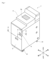
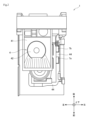
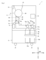
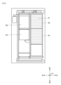
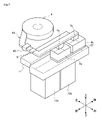
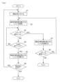
本実施の形態の硬貨処理装置の外観斜視図である。1 is an external perspective view of a coin processing apparatus according to an embodiment; FIG. 本実施の形態の硬貨処理装置の内部を真上から見た図である。It is the figure which looked at the inside of the coin processing apparatus of this Embodiment from right above. 本実施の形態の硬貨処理装置を右方向から見た構成図である。It is a block diagram which looked at the coin processing apparatus of this Embodiment from the right direction. 本実施の形態の図1の硬貨処理装置の断面A-Aである。2 is a cross section AA of the coin processing apparatus of FIG. 1 of the present embodiment. 本実施の形態の硬貨処理装置の硬貨を収納する構成を説明するための説明図である。It is an explanatory view for explaining the composition which stores the coin of the coin processor of form of this execution. 本実施の形態の硬貨処理装置の動作を説明するフローチャートである。It is a flow chart explaining operation of a coin processor of this embodiment.

以下、本発明の実施形態について説明する。以下に説明する本実施の形態は、本発明の技術的思想を具体化するための装置や方法を例示するものであって、本発明の技術的思想(構造、配置)は、下記のものに特定するものではない。本発明の技術的思想は、特許請求の範囲に記載された技術的範囲内において、種々の変更を加えることができる。図面は模式的なものであり、装置やシステムの構成等は現実のものとは異なる。また、既に公知な技術は説明を省略する。前後左右は、硬貨処理装置1の前(操作者が操作する場所から見て手前側)、硬貨処理装置1の後(操作者から見て奥側)および硬貨処理装置1の左右(操作者から見て左右)である。また、上下は前後、左右方向に垂直な方向をいうもので各図面に方向を座標で示す。 Embodiments of the present invention will be described below. The embodiment described below exemplifies an apparatus and method for embodying the technical idea of the present invention, and the technical idea (structure, arrangement) of the present invention is as follows It is not specific. Various modifications can be made to the technical idea of the present invention within the technical scope described in the claims. The drawings are schematic, and the configurations of devices and systems are different from the actual ones. Further, the description of already known techniques is omitted. The front, rear, left, and right are the front side of the coin processing device 1 (the front side when viewed from the operator's place), the rear side of the coin processing device 1 (the back side when viewed from the operator), and the left and right sides of the coin processing device 1 (from the operator). left and right). Moreover, up and down refer to directions perpendicular to the front, back, left and right directions, and the directions are indicated by coordinates in each drawing.

硬貨処理装置1は、ATMを含む金融機関のシステムにおいて、ATMとは別に設けられる硬貨の大量入金を可能とする。硬貨処理装置1は、投入された硬貨を識別計数する識別計数部45と、識別計数部45により硬貨を少なくとも二種に分けて一の種類に分けた硬貨を落下させる選別孔71a,71b(図3)と、選別孔71a,71bに設けられ、選別孔71a,71bを開閉する開閉機構72a,72b(図3)とを備え、計数開始時に開閉機構72a,72bにより選別孔71a,71bを開放させ、計数終了時に開閉機構72a,72bにより選別孔71a,71bを閉鎖する。 The coin processing apparatus 1 enables a large amount of coins to be deposited separately from an ATM in a system of a financial institution including an ATM. The coin processing apparatus 1 includes a discriminating counting section 45 for discriminating and counting the inserted coins, and sorting holes 71a and 71b (see FIG. 1) for separating the coins into at least two types by the discriminating counting section 45 and for dropping the coins divided into one type. 3) and opening/closing mechanisms 72a and 72b (FIG. 3) provided in the sorting holes 71a and 71b for opening and closing the sorting holes 71a and 71b. The sorting holes 71a and 71b are closed by the opening/closing mechanisms 72a and 72b at the end of counting.

<硬貨処理装置1の具体的構成>
硬貨処理装置1(図1)は、上部カバー2を備え、上部カバー2は装置後方の幅方向に軸線を有する水平軸を起点として、装置前方部が上方に向けて旋回開放可能に支持されている。上部カバー2の上面には、開閉装置であるシャッタ2aが設けられている。なお、図2は上部カバー2を開いた場合の見える状態を示している。上部カバー2の開閉検知部(図示しない)は、装置前方部に、上部カバー2が旋回して下りて来た上部カバー2の一部を検出する構造となっている。
<Specific Configuration of Coin Processing Device 1>
A coin processing machine 1 (FIG. 1) is provided with an upper cover 2, and the upper cover 2 is supported so that the front part of the machine can be turned upward about a horizontal axis having an axis in the width direction at the rear of the machine. there is The upper surface of the upper cover 2 is provided with a shutter 2a as an opening/closing device. Note that FIG. 2 shows a visible state when the upper cover 2 is opened. An opening/closing detector (not shown) of the upper cover 2 is configured to detect a part of the upper cover 2 that has turned and descended to the front of the apparatus.

台車3(図1)は、下部に設けられたキャスタ31を転動させることで、硬貨処理装置1に対し前面側に引き出される。さらに硬貨処理装置1から取り外されて運搬される一方、前面側から装填されることで硬貨処理装置1に装着されるようになっている。台車3には、図3に示すように、前後方向に並設して金庫12a,12bが設けられている。 The carriage 3 (FIG. 1) is pulled out to the front side with respect to the coin processing apparatus 1 by rolling casters 31 provided at the bottom. Further, it is detached from the coin handling machine 1 and transported, and is attached to the coin handling machine 1 by being loaded from the front side. As shown in FIG. 3, the truck 3 is provided with safes 12a and 12b arranged side by side in the front-rear direction.

硬貨計数部4(図3,図5)は、ホッパ41、回転円盤42、硬貨分離部43、硬貨通路44および識別計数部45を有する。ホッパ41は、シャッタ2aの直下に設けられ投入された硬貨を貯留する。回転円盤42は、ホッパ41の下側にその底部を形成するように設けられた水平旋回可能な円盤である。 The coin counting section 4 ( FIGS. 3 and 5 ) has a hopper 41 , a rotating disk 42 , a coin separating section 43 , a coin passage 44 and an identification counting section 45 . The hopper 41 is provided directly below the shutter 2a and stores the inserted coins. The rotating disc 42 is a horizontally rotatable disc that is provided below the hopper 41 so as to form its bottom.

硬貨分離部43は、硬貨が一枚のみ通過可能な開口を有し回転円盤42の回転時の遠心力で硬貨を一枚ずつ硬貨通路44に繰り出す。硬貨通路44は、硬貨分離部43で一枚ずつ繰り出された硬貨を水平に搬送する通路で、周知のように、図示せぬ搬送ベルトが硬貨通路44に沿って吊架され、上方から硬貨を硬貨通路44に押し付けるように搬送ベルトが配設されている。識別計数部45(図3,図5)は、硬貨通路44の上流側に設けられ、硬貨通路44で搬送中の硬貨の真偽及び金種を識別するとともに、それらの枚数を計数する。 The coin separating part 43 has an opening through which only one coin can pass, and feeds the coins one by one into the coin passage 44 by centrifugal force when the rotating disc 42 rotates. The coin passage 44 is a passage for horizontally conveying the coins fed out one by one by the coin separating section 43. As is well known, a conveying belt (not shown) is suspended along the coin passage 44 to convey the coins from above. A conveyor belt is arranged so as to press against the coin passage 44 . The identifying and counting unit 45 (FIGS. 3 and 5) is provided on the upstream side of the coin passage 44, identifies the authenticity and denomination of coins being conveyed in the coin passage 44, and counts the number of coins.

リジェクト部5は、硬貨計数部4の識別計数部45の計数結果に基づいて真貨以外のもの(以下、リジェクト硬貨と称する)をリジェクトボックス6に収納する。リジェクト部5は、リジェクト孔51と、リジェクト孔51に硬貨を落下させるためのリジェクト部材52と、上流側の硬貨センサ53を有している。硬貨センサ53は、リジェクト部材52の開閉タイミングを制御するために用いられる。リジェクトボックス6は、リジェクト部5で硬貨通路44から排除されたリジェクト硬貨を収納する着脱自在なボックスである。 The reject unit 5 stores items other than genuine coins (hereinafter referred to as rejected coins) in the reject box 6 based on the counting result of the identification counting unit 45 of the coin counting unit 4 . The reject part 5 has a reject hole 51 , a reject member 52 for dropping coins into the reject hole 51 , and an upstream coin sensor 53 . The coin sensor 53 is used to control opening/closing timing of the reject member 52 . The reject box 6 is a detachable box that stores the rejected coins that have been rejected from the coin passage 44 by the reject section 5 .

振分部7a及び7b(図3~図5)は、硬貨通路44におけるリジェクト部5の下流側に配置される。振分部7a及び7b(以下、個々に区別する必要がない場合、単に、振分部7と称する。他の場合も同様である)は、識別計数部45の計数結果に基づいて真の硬貨であって受け入れ可能と識別及び計数された硬貨を、一時貯留部8aまたは一時貯留部8bに振り分ける機構を有している。 The sorting sections 7a and 7b (FIGS. 3 to 5) are arranged downstream of the reject section 5 in the coin passage 44. As shown in FIG. Sorting units 7a and 7b (hereinafter simply referred to as sorting units 7 when there is no need to distinguish them individually; the same applies to other cases) sort out true coins based on the counting results of the identification counting unit 45. , and has a mechanism for allocating coins identified and counted as acceptable to the temporary storage portion 8a or the temporary storage portion 8b.

振分部7a及び振分部7bのそれぞれは、取り扱う最大径の硬貨(日本国内では500円硬貨)を落下可能な選別孔71a及び選別孔71bを有している。振分部7a及び振分部7bには、選別孔71a及び選別孔71bを個別に開閉可能な開閉機構(シャッタ)72aおよび開閉機構(シャッタ)72bが設けられている(図3)。 Each of the sorting section 7a and the sorting section 7b has a sorting hole 71a and a sorting hole 71b into which the maximum diameter coin to be handled (a 500-yen coin in Japan) can be dropped. The sorting section 7a and the sorting section 7b are provided with an opening/closing mechanism (shutter) 72a and an opening/closing mechanism (shutter) 72b capable of individually opening and closing the sorting holes 71a and 71b (FIG. 3).

開閉機構72a,72bは、例えばソレノイドを利用したものである。ソレノイドは電流を流すことによって、コイル内に磁界をつくる筒形コイルをいう。ソレノイドに係る直動アクチュエータは、パワー源から送られた直流によってコイルが励磁され、可動型の鉄心に、電磁力で応答の早い微小な直進運動を行わせるものである。ソレノイドを利用した開閉機構72a,72bは、可動型の鉄心に直結した開閉機構72a,72bによって開閉を高速で行われる。なお開閉機構72a,72bは、ソレノイドコイルを利用するものの他、カム機構を利用するなど他の方法でもよい。 The opening/closing mechanisms 72a and 72b use, for example, solenoids. A solenoid is a cylindrical coil that creates a magnetic field in the coil by passing an electric current through it. A direct-acting actuator related to a solenoid excites a coil with a direct current sent from a power source, and causes a movable iron core to perform minute rectilinear motion with quick response by electromagnetic force. The opening/closing mechanisms 72a and 72b using solenoids are opened and closed at high speed by the opening/closing mechanisms 72a and 72b directly connected to the movable iron cores. The opening/closing mechanisms 72a and 72b may use solenoid coils or other methods such as cam mechanisms.

一時貯留部8aは、平面視で四角状の枠体であり、振分部7aの下方に設けられている。一時貯留部8bは、平面視で四角状の枠体であり、振分部7bの下方に設けられている。振分部7aの開閉機構72aにより選別孔71aが開かれることで、選別孔71aに到達した硬貨は選別孔71aから一時貯留部8aに落下する。振分部7aの開閉機構72aにより振分部7aが閉じられると、硬貨は選別孔71bに到達し、選別孔71bが開状態の場合、硬貨は、選別孔71bから一時貯留部8bに落下する。 The temporary storage portion 8a is a rectangular frame in a plan view, and is provided below the distribution portion 7a. The temporary storage portion 8b is a rectangular frame in a plan view, and is provided below the distribution portion 7b. The sorting hole 71a is opened by the opening/closing mechanism 72a of the sorting section 7a, and the coins reaching the sorting hole 71a drop from the sorting hole 71a into the temporary storage section 8a. When the sorting portion 7a is closed by the opening/closing mechanism 72a of the sorting portion 7a, the coins reach the sorting hole 71b, and when the sorting hole 71b is open, the coins drop from the sorting hole 71b into the temporary storage portion 8b. .

一時貯留部8a,8bの底は、1枚の水平状の一時庫底板81で構成されている(図3,図5)。 The bottoms of the temporary storage portions 8a and 8b are composed of one horizontal temporary storage bottom plate 81 (FIGS. 3 and 5).

一時貯留部8a,8bは、一体的に装置筐体の左右方向に水平移動可能に支持されている。一時庫底板81も、一時貯留部8a,8bとは独立して左右方向に水平移動可能に支持されている。一時貯留部8a,8b、一時庫底板81が水平移動することにより硬貨を所定の場所に収納することができる。 The temporary reservoirs 8a and 8b are integrally supported so as to be horizontally movable in the lateral direction of the apparatus housing. The temporary storage bottom plate 81 is also supported so as to be horizontally movable in the horizontal direction independently of the temporary storage portions 8a and 8b. Coins can be stored in a predetermined place by horizontally moving the temporary storage portions 8a and 8b and the temporary storage bottom plate 81. As shown in FIG.

ガイド11(図5)は、一時貯留部8a,8bと一時庫底板81が左側に水平移動した際に、そこに格納されている硬貨を、金庫12a,12bに受け渡すために案内するガイドである。なお、ガイド11を設けずに、金庫12a,12bの高さをガイド11分高くして一時貯留部8a,8bに格納されている硬貨が金庫12a,12bに受け渡されるようにすることもできる。 The guide 11 (FIG. 5) guides the coins stored therein to the safes 12a and 12b when the temporary storage portions 8a and 8b and the temporary storage bottom plate 81 are horizontally moved to the left. be. It is also possible to increase the height of the safes 12a and 12b by the height of the guide 11 without providing the guide 11 so that the coins stored in the temporary storage portions 8a and 8b can be delivered to the safes 12a and 12b. .

金庫12a,12bは、一時貯留部8a,8bが装置筐体の左側部に沿って設けられた状態において、その下方に位置する場所に配置されている。 The safes 12a and 12b are arranged below the temporary storage sections 8a and 8b provided along the left side of the apparatus housing.

金庫12a,12bは、硬貨処理装置1に対して着脱可能な台車3に置かれている。なお、硬貨処理装置1に対して出し入れ可能なスライドレールに支持された金庫キャリアによって支持されるようにもできる。 The safes 12a and 12b are placed on a carriage 3 that is detachable from the coin handling machine 1. As shown in FIG. It should be noted that the coin handling machine 1 may be supported by a safe carrier supported by slide rails that can be put in and taken out of the coin handling machine 1 .

金庫12a,12bは、その上部が開口を有する箱体であり、且つその上部開口には、開口を開閉するシャッタ部材(図示せず)が設けられる。シャッタ部材は、金庫12a,12bが装置本体内に位置しているときには、上部開口を開放して、上方からの硬貨の受け入れを可能とされている。 The safes 12a and 12b are box bodies having openings at the top thereof, and the top openings are provided with shutter members (not shown) for opening and closing the openings. When the safes 12a and 12b are positioned inside the main body of the device, the shutter member opens the upper opening so that coins can be received from above.

金庫12a,12bのシャッタ部材は、金庫12a,12bが硬貨処理装置1内にある時に、回収指示を受けることで、それらの上部開口を閉じてロックされる。その後、装置筐体内から引き出すことができて、台車3ごと、または、スライドレールに支持された金庫キャリア上より、上部開口がシャッタ部材で閉じられた状態の金庫12a,12bを装置筐体外に引き出すことができるようになっている。 When the safes 12a and 12b are in the coin handling apparatus 1, the shutter members of the safes 12a and 12b are locked by closing their upper openings by receiving a recovery instruction. After that, the safes 12a and 12b with their upper openings closed by the shutter members can be pulled out of the device housing together with the carriage 3 or on the safe carrier supported by the slide rails. It is possible to do so.

金庫12a,12bは、硬貨処理装置1外にあるときには、専用のカギによって、シャッタまたは開放蓋(図示せず)を開いて、収納している硬貨を取り出すことができるようになっている。 When the safes 12a and 12b are outside the coin processing apparatus 1, the shutters or opening lids (not shown) can be opened with a dedicated key to take out the stored coins.

表示操作部13(図3)は、利用者への情報表示を行うとともに利用者による操作入力を受け付ける。制御部14は、各部を制御して、硬貨処理装置1における硬貨入金処理を実行する。 The display/operation unit 13 (FIG. 3) displays information to the user and receives operation inputs from the user. The control unit 14 controls each unit to perform coin deposit processing in the coin processing device 1 .

<硬貨処理装置1の硬貨入金処理>
図6は、硬貨入金処理を説明するフローチャートである。利用者によりATMに対して大量硬貨入金のための操作がなされ、ATMから大量硬貨入金があることの指示を受けると、ステップS1において、硬貨処理装置1の制御部14は、シャッタ2aを開かせて硬貨を受け付ける。なお、ATMから大量硬貨入金の指示を受ける前を含め、この時点でも、硬貨通路44の選別孔71a,71bは開閉機構72a,72bによって閉じられた状態で待機している。
<Coin Deposit Processing of Coin Handling Device 1>
FIG. 6 is a flowchart for explaining coin deposit processing. When the user operates the ATM to deposit a large amount of coins and receives an instruction from the ATM that there is a large amount of coins to be deposited, the control unit 14 of the coin processing device 1 opens the shutter 2a in step S1. to accept coins. Even at this time, including before receiving an instruction to deposit a large amount of coins from the ATM, the sorting holes 71a and 71b of the coin passage 44 are on standby with the opening/closing mechanisms 72a and 72b closed.

また、利用者がATMに対して計数を開始するための操作を行うと、ステップS2において、制御部14は、シャッタ2aを閉じるとともに、識別計数処理を実行する。この時点、すなわち計数開始時点において、硬貨通路44の選別孔71a,71bは開閉機構72a,72bによって閉じられた状態から開いた状態に変更制御される(シャッタが開く)。なお、選別孔71a,71bの両方を同時に開いても良いし、いずれか一方のみを開くように制御しても良い。ここにおいて、識別計数処理が実行されると、回転する回転円盤42上の硬貨が1枚ずつに分離されて硬貨通路44の上方に配置された搬送ベルト(図示せず)に送られる。搬送ベルトによって、硬貨が硬貨通路44面に押し付けられながら、硬貨通路44を下流に向けて搬送される。シャッタ2aから投入された硬貨の識別および計数が開始される。 Also, when the user performs an operation for starting counting on the ATM, in step S2, the control unit 14 closes the shutter 2a and executes identification counting processing. At this point, that is, at the start of counting, the sorting holes 71a and 71b of the coin passage 44 are controlled to be changed from the closed state to the open state (the shutter opens) by the opening/closing mechanisms 72a and 72b. Both the sorting holes 71a and 71b may be opened at the same time, or only one of them may be opened. Here, when the identification counting process is executed, the coins on the rotating rotary disk 42 are separated one by one and sent to a conveyor belt (not shown) arranged above the coin passage 44 . The conveying belt conveys the coin downstream in the coin passage 44 while pressing the coin against the surface of the coin passage 44 . Identification and counting of coins inserted from the shutter 2a are started.

このとき、上記した通り、制御部14は、開閉機構72a,72bを制御して選別孔71a,71bを開閉させ、識別計数部45の計数結果に基づいて真の硬貨であって、受け入れ可能と識別及び計数された硬貨の、一時貯留部8aまたは一時貯留部8bへの振り分けを行う。一時貯留部8aに硬貨を振り分ける場合、選別孔71aが開くように制御され、選別孔71aから硬貨が時貯留部8aに落下する。一時貯留部8bに硬貨を振り分ける場合、選別孔71aが閉じ、選別孔71bが開くように制御され、選別孔71bから硬貨が時貯留部8bに落下する。なお選別孔71bが開いていても、上流側の選別孔71aが開いていればそこから硬貨が落下するので、処理を簡単にするために、識別計数処理が開始されると、選別孔71bは開かれる。 At this time, as described above, the control section 14 controls the opening/closing mechanisms 72a and 72b to open and close the sorting holes 71a and 71b, and based on the counting result of the identification counting section 45, the coin is a true coin and can be accepted. The identified and counted coins are distributed to the temporary storage section 8a or the temporary storage section 8b. When sorting coins to the temporary storage portion 8a, the sorting hole 71a is controlled to open, and the coins drop from the sorting hole 71a into the temporary storage portion 8a. When sorting coins to the temporary storage portion 8b, the sorting hole 71a is closed and the sorting hole 71b is controlled to open, and the coins drop from the sorting hole 71b into the temporary storage portion 8b. Note that even if the sorting hole 71b is open, if the sorting hole 71a on the upstream side is open, coins will drop from there. be opened.

識別計数部45で真の硬貨と識別できなかった硬貨(リジェクト硬貨)がリジェクト部5の硬貨センサ53で検出されると、制御部14は、リジェクト部材52を開く制御を行う。その結果、硬貨センサ53で検出されたリジェクト硬貨は、リジェクト孔51を通って、リジェクトボックス6に収納される。なお、取り扱い対象となっていない記念硬貨や外国の真貨であっても、偽貨としてリジェクトボックス6に収納される。リジェクトボックス6への偽貨等排除がなされた場合には、ATMにおいてその旨が表示され、硬貨処理装置1の装置本体前面のLED(図示せず)での点灯・点滅がなされるので、利用者は偽貨等の排除物を確実に回収できる。 When the coin sensor 53 of the rejecting unit 5 detects a coin (rejected coin) that cannot be discriminated from a true coin by the identification counting unit 45 , the control unit 14 performs control to open the rejecting member 52 . As a result, the rejected coin detected by the coin sensor 53 passes through the reject hole 51 and is received in the reject box 6 . Note that even commemorative coins and foreign genuine coins that are not subject to handling are stored in the reject box 6 as counterfeit coins. When a counterfeit coin or the like is removed from the reject box 6, the ATM displays a message to that effect, and an LED (not shown) on the front face of the coin processing device 1 lights up or flashes, so that it can be used. The person can reliably collect the excluded items such as counterfeit goods.

ステップS3において、制御部14は、エラーが発生したか否かを判定する。例えば、上部カバー2が開かれた場合、計数停止ボタン(図示せず)が操作され計数停止が要求された場合、または電源系の異常(例えば、急な電源断状態)が発生した場合、エラーが発生したと判定される。 In step S3, the control unit 14 determines whether or not an error has occurred. For example, when the upper cover 2 is opened, when a counting stop button (not shown) is operated to request counting stop, or when an abnormality in the power system (for example, sudden power failure) occurs, an error occurs. is determined to have occurred.

ステップS3で、エラーが発生してないと判定した場合、制御部14は、ステップS4において、入金が完了した否かを判定する。回転円盤42上に硬貨が存在しないことが図示せぬセンサで検出され、かつ、最後に識別計数部45で正常に硬貨識別された硬貨が少なくとも最下流の選別孔72bに導かれるのに必要な時間が経過したとき、入金が完了した判定される。ステップS4で、入金が終了していないと判定した場合、制御部14は、ステップS3に戻り、それ以降の処理を同様に実行する。 If it is determined in step S3 that no error has occurred, the control unit 14 determines in step S4 whether or not the payment has been completed. A sensor (not shown) detects that there are no coins on the rotating disk 42, and the coins that are finally correctly identified by the identification and counting unit 45 are guided to at least the most downstream sorting hole 72b. When the time has passed, it is determined that the deposit has been completed. If it is determined in step S4 that the payment has not been completed, the control unit 14 returns to step S3 and similarly executes the subsequent processes.

ステップS4で、入金が完了したと判定した場合、制御部14は、ステップS5において、識別計数処理を一旦停止(計数終了)させ、すなわち、回転円盤42の回転と搬送ベルト(図示せず)の駆動を停止させるとともに、硬貨通路44の選別孔71a,71bを開閉機構72a,72bによって閉じる(シャッタを閉める)。その上で、ステップS6において、制御部14は、再計数する硬貨があるか否かを判定する。ここで、再計数とは、リジェクト硬貨等の選別孔71a,71bへ導けなかった硬貨を含む。再計数する硬貨があると判定した場合、処理はステップS1に戻り、それ以降の処理が実行される。ステップS6で、再計数する硬貨が無いと判定した場合、制御部14は、開閉機構72a,72bを閉じたままで硬貨入金処理を終了する。ここにおいて、ステップS6の再計数の有無の判定に際しては、利用者に対する再計数を希望するか否かの照会を行いつつ、一定時間の間に再計数の希望が示されたときには、硬貨の再投入を可能とするべくシャッタ2aを開き(ステップS1)、他方、一定時間の間に再計数の希望が示されなかったときには、そのまま、硬貨入金処理を終了させたり、あるいは、利用者への再計数の希望の照会を行う代わりに、硬貨の再投入ないしは追加投入を可能とするべくシャッタ2aを開き、一定時間の間に、シャッタ2a・ホッパ41・回転円盤42内への硬貨の投入の有無を確認して、硬貨の投入があったときには再計数すべきものとしてステップ2へ戻り、硬貨の投入が確認できなかったときには再計数不要として、シャッタ2aを閉じたうえで硬貨入金処理を終了させるようにしても良い。 When it is determined in step S4 that the deposit has been completed, the control unit 14 temporarily stops the identification counting process (finishes counting) in step S5. The driving is stopped, and the sorting holes 71a and 71b of the coin passage 44 are closed by the opening/closing mechanisms 72a and 72b (the shutter is closed). After that, in step S6, the control unit 14 determines whether or not there are coins to be recounted. Here, recounting includes coins such as rejected coins that could not be guided to the sorting holes 71a and 71b. If it is determined that there are coins to be recounted, the process returns to step S1 and the subsequent processes are executed. When it is determined in step S6 that there are no coins to be recounted, the control unit 14 ends the coin deposit process while keeping the opening/closing mechanisms 72a and 72b closed. Here, when determining whether or not to recount in step S6, the user is inquired as to whether or not he/she desires recounting. The shutter 2a is opened to allow the insertion of coins (step S1). On the other hand, if no request for recounting is indicated within a certain period of time, the coin receiving process is terminated or the recount is sent to the user. Instead of inquiring about the desired count, the shutter 2a is opened to allow re-insertion or additional insertion of coins, and presence or absence of insertion of coins into the shutter 2a, the hopper 41, and the rotating disk 42 within a certain period of time. If a coin has been inserted, the process returns to step 2 assuming that the coin should be recounted. If no coin has been inserted, the shutter 2a is closed and the coin receiving process is terminated. You can do it.

他方、ステップS3で、エラーが発生したと判定した場合、制御部14は、ステップS7に進み、識別計数処理を一旦停止(計数終了)させ、識別計数部45の直前に設けられた硬貨搬送停止部(図示せず)を制御し、エラーが発生前の硬貨通路44上流の硬貨の搬送を阻止し、識別計数部45で正常に硬貨識別された硬貨に限り、選別孔71a,71bに導くようにした上で、制御部14は、また開閉機構72a,72bを制御して、選別孔71a,71bを閉じさせる(シャッタを閉める)。 On the other hand, if it is determined in step S3 that an error has occurred, the control unit 14 advances to step S7, temporarily stops the identification counting process (ends counting), and stops the coin conveyance provided immediately before the identification counting unit 45. (not shown) to prevent coins from being conveyed upstream of the coin passage 44 before an error occurs, and guide only coins correctly identified by the identifying and counting unit 45 to the sorting holes 71a and 71b. After that, the control unit 14 also controls the opening/closing mechanisms 72a and 72b to close the sorting holes 71a and 71b (close the shutters).

なおエラーが発生した際、選別孔71a,71b内に導いた硬貨の計数結果に異常があると認められると、選別した硬貨の返却と再計数が行われる。また選別孔71a,71b内に導いた硬貨の計数結果に異常が無いと認められる場合、選別した硬貨はそのままとされ、異常が発生したことについての確認だけが行われる。 When an error occurs, if the coins guided into the sorting holes 71a and 71b are found to be abnormal, the sorted coins are returned and counted again. Further, when it is recognized that there is no abnormality in the counting result of the coins guided into the sorting holes 71a and 71b, the sorted coins are left as they are, and only confirmation of the occurrence of abnormality is performed.

次に、ステップS8において、制御部14は、エラーが解消したか否かを判定し、エラーが解消したと判定した場合、ステップS2に戻り、識別計数処理を再開する。ステップS8でエラーが解消しないと判定した場合、制御部14は、硬貨入金処理を終了する。 Next, in step S8, the control unit 14 determines whether or not the error has been resolved. If it is determined that the error has been resolved, the process returns to step S2 to restart the identification counting process. If it is determined in step S8 that the error has not been resolved, the control unit 14 terminates the coin receiving process.

上述のように、硬貨処理装置1において、投入された硬貨を識別計数する識別計数部45と、識別計数部45により硬貨を少なくとも二種に分けて、一の種類に分けた硬貨を落下させる選別孔71a,71bと、当該選別孔71a,71bを開閉する開閉機構72a,72bとを備え、計数開始時に開閉機構72a,72bにより選別孔71a,71bが開放され(ステップS2)、計数終了時に開閉機構72a,72bにより選別孔71a,71bを閉鎖される(ステップS5,S7)。そのため、計数終了時には、選別孔71a,71bも閉じているので、外部に、選別孔71a,71bを介して一時貯留部8a,8bが露出しない。したがって計数終了時のタイミングにおいて、第三者が、選別孔71a,71bから一時貯留部8a,8bに収納された硬貨を取り出し得ることができない。また計数されていない硬貨が落下し、選別孔71a,71bを介して一時貯留部8a,8bに収納されてしまうことがない。すなわち計数結果に対する信頼性を保つことができる。 As described above, in the coin processing device 1, the identification counting section 45 that identifies and counts the inserted coins, and the identification counting section 45 divides the coins into at least two types, and sorts the coins divided into one type to drop. Holes 71a and 71b and opening/closing mechanisms 72a and 72b for opening and closing the sorting holes 71a and 71b are provided. The sorting holes 71a and 71b are closed by the mechanisms 72a and 72b (steps S5 and S7). Therefore, the sorting holes 71a and 71b are also closed at the end of counting, so that the temporary storage portions 8a and 8b are not exposed to the outside through the sorting holes 71a and 71b. Therefore, at the timing when counting ends, a third party cannot take out the coins stored in the temporary storage portions 8a and 8b through the sorting holes 71a and 71b. In addition, uncounted coins do not drop and are stored in the temporary storage portions 8a and 8b through the sorting holes 71a and 71b. That is, the reliability of counting results can be maintained.

また上述したように再計数または追加計数を開始可能とし、再計数または追加計数開始時に開閉機構により選別孔を開放させ(ステップS6YESの後のステップ2)、再計数または追加計数終了時に開閉機構72a,72bにより選別孔71a,71bを閉鎖することとしたので(ステップS6YESの後のステップ5またはその後)、当初の計数時と再計数または追加計数との間の時間帯であっても、選別孔71a,71bが開閉機構72a,72bによって閉鎖状態に維持されているので、計数結果に対する信頼性を保つことができる。 Further, as described above, recounting or additional counting can be started, and when recounting or additional counting is started, the sorting hole is opened by the opening/closing mechanism (step 2 after step S6 YES), and when recounting or additional counting ends, opening/closing mechanism 72a is opened. , 72b to close the sorting holes 71a, 71b (step 5 after step S6 YES or after), even during the period between the initial counting and the recounting or additional counting, the sorting holes Since 71a and 71b are kept closed by the opening/closing mechanisms 72a and 72b, the reliability of the counting result can be maintained.

異常検知に伴って開閉機構72a,72bにより選別孔71a,71bを閉鎖に制御し(ステップS7)、異常検知後の正常検知ないしはエラー解消検知に伴って開閉機構72a,72bにより選別孔71a,71bを開放可能に制御される(ステップS8YESの後のステップS2)。例えば搬送ジャムが発生した場合、上部カバーを開放し、搬送ベルトを退避させて処理を行うが、その際、図2に示すように、振分部7a、7b(具体的には選別孔71a、71b)が表に出る構成となっているが、開閉機構72a,72bにより選別孔71a,71bが閉じられているので、第三者が、選別孔71a,71bから一時貯留部8a,8bに収納された硬貨を取り出し得ることができない。また計数されていない硬貨が落下し、選別孔71a,71bを介して一時貯留部8a,8bに収納されてしまうことがない。すなわち計数結果に対する信頼性を保つことができる。
なお、本実施の形態においては、選別孔71a,71b、開閉機構72a,72b、一時貯留部8a,8b、金庫12a,12bを二個ずつ設けた構成で説明したが、これに限るものではなく、一個ずつでも、または三個ずつ以上であっても、含まれるものである。
Upon detecting an abnormality, the opening/closing mechanisms 72a and 72b control the sorting holes 71a and 71b to be closed (step S7). can be opened (step S2 after step S8 YES). For example, when a conveying jam occurs, the upper cover is opened and the conveying belt is retracted for processing. At that time, as shown in FIG. 71b) is exposed to the outside, but since the sorting holes 71a and 71b are closed by the opening/closing mechanisms 72a and 72b, a third party can store them in the temporary storage portions 8a and 8b through the sorting holes 71a and 71b. You can't get the coins that have been played out. In addition, uncounted coins do not drop and are stored in the temporary storage portions 8a and 8b through the sorting holes 71a and 71b. That is, the reliability of counting results can be maintained.
In the present embodiment, two sorting holes 71a and 71b, opening/closing mechanisms 72a and 72b, temporary storage portions 8a and 8b, and safes 12a and 12b are provided. , one at a time, or three or more at a time, are included.

1 硬貨処理装置
2 上部カバー
3 台車
4 硬貨計数部
5 リジェクト部
6 リジェクトボックス
7 振分部
8 一時貯留部
9 シュート空間枠
11 ガイド
12 金庫
14 制御部
1 coin processing device 2 upper cover 3 cart 4 coin counting unit 5 reject unit 6 reject box 7 sorting unit 8 temporary storage unit 9 chute space frame 11 guide 12 safe 14 control unit

Claims (3)

硬貨処理装置であって、
投入された硬貨を識別計数する識別計数部と、
前記識別計数部により硬貨を少なくとも二種に分けて、一の種類に分けた硬貨を落下させる選別孔と、
前記選別孔に設けられ、当該選別孔を開閉する開閉機構と、
計数開始時に前記開閉機構により前記選別孔を開放させ、計数終了時に前記開閉機構により前記選別孔を閉鎖する制御を行う制御部とを備えた硬貨処理装置。
A coin handling device,
an identification counting unit that identifies and counts inserted coins;
a sorting hole for separating coins into at least two types by the identification and counting unit and dropping the coins divided into one type;
an opening and closing mechanism provided in the sorting hole for opening and closing the sorting hole;
a control unit that controls the opening and closing mechanism to open the sorting hole when counting is started and the opening and closing mechanism to close the sorting hole when counting is finished.
前記制御部は、硬貨の再投入または追加投入がされる場合、前記開閉機構により前記選別孔を開放させ、再計数または追加計数終了時に前記開閉機構により前記選別孔を再び閉鎖に制御することを特徴とする請求項1記載の硬貨処理装置。 When coins are reinserted or additionally inserted, the control unit causes the opening/closing mechanism to open the sorting hole, and controls the opening/closing mechanism to close the sorting hole again at the end of recounting or additional counting. 2. A coin handling machine according to claim 1. 前記制御部は、異常検知に伴って前記開閉機構により前記選別孔を閉鎖に制御し、異常検知後の正常検知に伴って前記開閉機構により前記選別孔を開放可能に制御することを特徴とする請求項1または2記載のいずれか1項記載の硬貨処理装置。

The control unit controls the opening/closing mechanism to close the sorting hole when an abnormality is detected, and controls the opening/closing mechanism to open the sorting hole when the normality is detected after the abnormality is detected. 3. The coin processing device according to claim 1 or 2.

JP2021122778A 2021-07-27 2021-07-27 Coin Processing Device Active JP7565045B2 (en)

Priority Applications (1)

Application Number Priority Date Filing Date Title
JP2021122778A JP7565045B2 (en) 2021-07-27 2021-07-27 Coin Processing Device

Applications Claiming Priority (1)

Application Number Priority Date Filing Date Title
JP2021122778A JP7565045B2 (en) 2021-07-27 2021-07-27 Coin Processing Device

Publications (2)

Publication Number Publication Date
JP2023018564A true JP2023018564A (en) 2023-02-08
JP7565045B2 JP7565045B2 (en) 2024-10-10

Family

ID=85158111

Family Applications (1)

Application Number Title Priority Date Filing Date
JP2021122778A Active JP7565045B2 (en) 2021-07-27 2021-07-27 Coin Processing Device

Country Status (1)

Country Link
JP (1) JP7565045B2 (en)

Also Published As

Publication number Publication date
JP7565045B2 (en) 2024-10-10

Similar Documents

Publication Publication Date Title
JPS599786A (en) Automatic coin teller equipment
CN101377868B (en) Equipment capable of sorting, ironing, disinfecting stored banknote in a bank counter to be fetched by drawing person
JP2015102926A (en) Coin processing apparatus
JP6296762B2 (en) Money handling machine and money handling method
JP2686068B2 (en) Banknote handling equipment
JP3547648B2 (en) Coin depositing and dispensing machine
JP2023018564A (en) coin handling equipment
JP6757023B2 (en) Coin deposit / withdrawal device
JP2017156990A (en) Coin processing apparatus, coin processing system and coin processing method
JP6557964B2 (en) Banknote handling equipment
JP3423645B2 (en) Coin depositing and dispensing machine
JP6681234B2 (en) Money handling equipment
JPH022477A (en) Coin processor with carrying fault recovery checking function
JP5436182B2 (en) Money handling machine
JP7565044B2 (en) Coin deposit device
JPH0973569A (en) Coin processing equipment
JP6580173B2 (en) Money handling machine and money handling method
JP5436290B2 (en) Coin handling machine
JP6697337B2 (en) Coin handling equipment
JPS61220087A (en) Circulation type coin teller machine
JP6174736B2 (en) Money handling system
JP2017182351A (en) Coin processor
JP5651765B2 (en) Money handling system
WO2010049994A1 (en) Currency processing device
JP3655141B2 (en) Coin deposit and withdrawal machine

Legal Events

Date Code Title Description
A621 Written request for application examination

Free format text: JAPANESE INTERMEDIATE CODE: A621

Effective date: 20231024

RD02 Notification of acceptance of power of attorney

Free format text: JAPANESE INTERMEDIATE CODE: A7422

Effective date: 20231024

A977 Report on retrieval

Free format text: JAPANESE INTERMEDIATE CODE: A971007

Effective date: 20240531

A131 Notification of reasons for refusal

Free format text: JAPANESE INTERMEDIATE CODE: A131

Effective date: 20240618

RD07 Notification of extinguishment of power of attorney

Free format text: JAPANESE INTERMEDIATE CODE: A7427

Effective date: 20240619

A521 Request for written amendment filed

Free format text: JAPANESE INTERMEDIATE CODE: A821

Effective date: 20240619

A521 Request for written amendment filed

Free format text: JAPANESE INTERMEDIATE CODE: A523

Effective date: 20240717

TRDD Decision of grant or rejection written
A01 Written decision to grant a patent or to grant a registration (utility model)

Free format text: JAPANESE INTERMEDIATE CODE: A01

Effective date: 20240903

A61 First payment of annual fees (during grant procedure)

Free format text: JAPANESE INTERMEDIATE CODE: A61

Effective date: 20240919

R150 Certificate of patent or registration of utility model

Ref document number: 7565045

Country of ref document: JP

Free format text: JAPANESE INTERMEDIATE CODE: R150

S111 Request for change of ownership or part of ownership

Free format text: JAPANESE INTERMEDIATE CODE: R313115

S531 Written request for registration of change of domicile

Free format text: JAPANESE INTERMEDIATE CODE: R313531

S533 Written request for registration of change of name

Free format text: JAPANESE INTERMEDIATE CODE: R313533

R350 Written notification of registration of transfer

Free format text: JAPANESE INTERMEDIATE CODE: R350