JP2023056830A - clothing processing equipment - Google Patents

clothing processing equipment Download PDF

Info

Publication number
JP2023056830A
JP2023056830A JP2021166270A JP2021166270A JP2023056830A JP 2023056830 A JP2023056830 A JP 2023056830A JP 2021166270 A JP2021166270 A JP 2021166270A JP 2021166270 A JP2021166270 A JP 2021166270A JP 2023056830 A JP2023056830 A JP 2023056830A
Authority
JP
Japan
Prior art keywords
connector
lid member
cover
lead wire
main body
Prior art date
Legal status (The legal status is an assumption and is not a legal conclusion. Google has not performed a legal analysis and makes no representation as to the accuracy of the status listed.)
Granted
Application number
JP2021166270A
Other languages
Japanese (ja)
Other versions
JP7623262B2 (en
Inventor
滉大 山田
Kodai Yamada
克則 松下
Katsunori Matsushita
陽祐 池田
Yosuke Ikeda
Current Assignee (The listed assignees may be inaccurate. Google has not performed a legal analysis and makes no representation or warranty as to the accuracy of the list.)
Toshiba Lifestyle Products and Services Corp
Original Assignee
Toshiba Lifestyle Products and Services Corp
Priority date (The priority date is an assumption and is not a legal conclusion. Google has not performed a legal analysis and makes no representation as to the accuracy of the date listed.)
Filing date
Publication date
Application filed by Toshiba Lifestyle Products and Services Corp filed Critical Toshiba Lifestyle Products and Services Corp
Priority to JP2021166270A priority Critical patent/JP7623262B2/en
Priority to CN202211088135.9A priority patent/CN115948899A/en
Publication of JP2023056830A publication Critical patent/JP2023056830A/en
Application granted granted Critical
Publication of JP7623262B2 publication Critical patent/JP7623262B2/en
Active legal-status Critical Current
Anticipated expiration legal-status Critical

Links

Images

Landscapes

  • Main Body Construction Of Washing Machines And Laundry Dryers (AREA)
  • Detail Structures Of Washing Machines And Dryers (AREA)

Abstract

To provide a clothing treatment device which includes a lid member having excellent waterproofness.SOLUTION: A clothing treatment device includes: a body having a body opening part opening upward; a lid member 30 rotatably supported at an upper part of the body and for opening/closing the body opening part, and having a first surface facing outward of the body, a second surface 302 opposing to the first surface and facing the body opening part side, and a hinge part 303 where a rotary shaft is positioned; a display device provided inside the lid member 30 and for displaying information from the first surface side so as to be visible; and a connector 53 for connecting a lead wire 50 connected to the display device and a lead wire 50 extending from the body. The lid member 30 includes: a connector storage part 322 for storing the connector 53 inside; and a cover member 34 for covering the connector storage part 322.SELECTED DRAWING: Figure 12

Description

本発明の実施形態は、衣類処理装置に関する。 Embodiments of the present invention relate to clothes processing devices.

いわゆる縦軸型の洗濯機において、本体内部に上面が開口した洗濯槽を備え、本体の上部に設けられたトップカバーに洗濯槽の上方に位置する出入口を設け、出入口を開閉する洗濯機蓋はトップカバーのヒンジ部によって回動可能に支持されている。 In a so-called vertical axis type washing machine, a washing machine with an open upper surface is provided inside the main body, a top cover provided on the upper part of the main body is provided with an entrance located above the washing tub, and a washing machine lid that opens and closes the entrance is It is rotatably supported by the hinge portion of the top cover.

近年、洗濯機蓋の上面に表示装置を設けた構成が開発されている。表示装置の基板が洗濯機蓋の内部に収容されている場合、洗濯機本体に設けられた制御装置と基板とを接続するリード線は、例えばヒンジ部を通って洗濯機本体から洗濯機蓋側に導かれる。 In recent years, a configuration has been developed in which a display device is provided on the upper surface of the lid of a washing machine. When the substrate of the display device is accommodated inside the washing machine lid, the lead wire connecting the substrate and the control device provided in the washing machine main body passes through, for example, the hinge portion and extends from the washing machine main body to the washing machine lid side. led to.

洗濯機は運転時に水や液状の洗濯処理剤を使用するため、表示装置の基板に水や液体が侵入しないように、防水性能を高めることが好ましい。 Since a washing machine uses water or a liquid washing treatment agent during operation, it is preferable to improve waterproof performance so that water or liquid does not enter the substrate of the display device.

特開2017-131424号公報JP 2017-131424 A

そこで、防水性に優れた蓋部材を備えた衣類処理装置を提供する。 Therefore, a clothing processing apparatus having a cover member with excellent waterproofness is provided.

実施形態の衣類処理装置は、上方に向けて開口した本体開口部を有する本体と、前記本体の上部に回動可能に支持されて前記本体開口部を開閉し、前記本体の外側を向いた第1面と、前記第1面に対向して前記本体開口部側を向いた第2面と、回動軸が位置するヒンジ部と、を有する蓋部材と、前記蓋部材の内部に設けられて前記第1面側から視認可能に情報を表示する表示装置と、前記表示装置に接続されたリード線と、前記本体から延びるリード線と、を接続するコネクタと、を備える。前記蓋部材は、内部に前記コネクタを収容するコネクタ収容部と、前記コネクタ収容部を覆うカバー部材と、を有する。 A laundry processing apparatus according to an embodiment includes a main body having a main body opening that opens upward, and a second main body that is rotatably supported on the upper part of the main body to open and close the main body opening and faces the outside of the main body. a lid member having one surface, a second surface facing the main body opening side facing the first surface, and a hinge portion on which a rotation shaft is positioned; A display device for displaying information to be visible from the first surface side, a connector for connecting a lead wire connected to the display device, and a lead wire extending from the main body. The lid member has a connector accommodating portion that accommodates the connector therein, and a cover member that covers the connector accommodating portion.

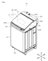
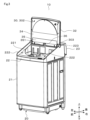
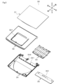
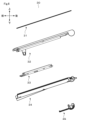
一実施形態による洗濯機の外観を示すもので、蓋部材が閉じた閉鎖状態を示す斜視図1 is a perspective view showing an appearance of a washing machine according to an embodiment, showing a closed state in which a lid member is closed; FIG. 一実施形態による洗濯機の内部構成を概略的に示す断面図FIG. 1 is a cross-sectional view schematically showing the internal configuration of a washing machine according to one embodiment; 一実施形態による洗濯機の外観を示すもので、蓋部材が開いた開放状態を示す斜視図1 is a perspective view showing an appearance of a washing machine according to one embodiment, showing an open state in which a lid member is opened; FIG. 一実施形態による洗濯機の蓋部材を第2面側から示す図The figure which shows the cover member of the washing machine by one Embodiment from the 2nd surface side. 一実施形態による洗濯機の蓋部材の主要な構成を示す分割斜視図FIG. 2 is a split perspective view showing the main configuration of the lid member of the washing machine according to one embodiment; 一実施形態による洗濯機の蓋部材の主要な構成を示す分割右側面図FIG. 2 is a split right side view showing the main configuration of the lid member of the washing machine according to one embodiment; 一実施形態による洗濯機の支持部材を第2面側から見た図The figure which looked at the support member of the washing machine by one Embodiment from the 2nd surface side 一実施形態による洗濯機の基板保持部材を第2面側から見た図The figure which looked at the board|substrate holding member of the washing machine by one Embodiment from the 2nd surface side 一実施形態による洗濯機のメインカバーを第2面側から見た図The figure which looked at the main cover of the washing machine by one Embodiment from the 2nd surface side 一実施形態による洗濯機のヒンジ部カバーを第2面側から見た図The figure which looked at the hinge part cover of the washing machine by one Embodiment from the 2nd surface side 一実施形態による洗濯機の蓋部材からヒンジ部カバーを外して第2面側から見た図The figure which removed the hinge part cover from the cover member of the washing machine by one Embodiment, and was seen from the 2nd surface side. 一実施形態による洗濯機の蓋部材からヒンジ部カバーを外した状態でメインカバーの一部を取り除いて第2面側から見た図FIG. 11 is a view of the washing machine according to one embodiment, with the hinge cover removed from the lid member and the main cover partially removed, viewed from the second surface side; 一実施形態による洗濯機の支持部材のコネクタ収容部周辺を第2面側から見た図The figure which looked at the connector accommodating part periphery of the supporting member of the washing machine by one Embodiment from the 2nd surface side. その他の実施形態による洗濯機の支持部材のコネクタ収容部周辺を第2面側から見た図The figure which looked at the connector accommodating part periphery of the supporting member of the washing machine by other embodiment from the 2nd surface side. 一実施形態による洗濯機のコネクタを図13のXV-XV線に沿って示す断面図FIG. 13 is a cross-sectional view showing the connector of the washing machine according to one embodiment along line XV-XV of FIG. 13; 一実施形態による洗濯機の防水部材に被覆された状態のリード線を示す断面図FIG. 2 is a cross-sectional view showing a lead wire covered with a waterproof member of a washing machine according to one embodiment;

以下、一の実施形態について図面を参照して説明する。図1~図3に示す衣類処理装置としての洗濯機10は、本体20、水槽11、回転槽12、モータ13、排水弁14、給水弁15、給水経路16、及び表示装置17を備えている。なお、図1の左手前側を洗濯機10の前側とし、図1の右奥側を洗濯機10の後側とする。洗濯機10の使用時に、ユーザは、洗濯機10の前側に位置するものとする。また、洗濯機10の設置面側つまり鉛直下側を、洗濯機10の下側とし、設置面と反対側つまり鉛直上側を、洗濯機10の上側とする。そして、洗濯機10の前後方向及び上下方向に対して直角方向を、洗濯機10の幅方向すなわち左右方向とする。 One embodiment will be described below with reference to the drawings. A washing machine 10 as a clothes processing apparatus shown in FIGS. 1 to 3 includes a main body 20, a water tub 11, a rotating tub 12, a motor 13, a drain valve 14, a water supply valve 15, a water supply path 16, and a display device 17. . 1 is the front side of washing machine 10, and the rear right side of FIG. 1 is the rear side of washing machine 10. As shown in FIG. It is assumed that the user is positioned on the front side of the washing machine 10 when using the washing machine 10 . The installation surface side of the washing machine 10 , that is, the vertically lower side is the lower side of the washing machine 10 , and the opposite side to the installation surface, that is, the vertically upper side is the upper side of the washing machine 10 . A direction perpendicular to the front-rear direction and the up-down direction of the washing machine 10 is defined as the width direction of the washing machine 10, that is, the left-right direction.

本実施形態の洗濯機10は、回転槽12の回転軸が鉛直方向を向いたいわゆる縦軸型の洗濯機である。なお、洗濯機10は、縦軸型に限らず、例えば回転槽12の回転軸が地面に対して水平又は傾斜したいわゆるドラム式の洗濯機であっても良い。また、洗濯機10は、乾燥機能を備えていても良いし、備えていなくても良い。 The washing machine 10 of the present embodiment is a so-called vertical axis type washing machine in which the rotating shaft of the rotating tub 12 faces the vertical direction. The washing machine 10 is not limited to the vertical axis type, and may be a so-called drum type washing machine in which the rotation axis of the rotating tub 12 is horizontal or inclined with respect to the ground. Moreover, the washing machine 10 may or may not have a drying function.

本体20は、図1に示すように、箱体21、トップカバー22、バックカバー23、及び蓋部材30を有している。箱体21は、洗濯機10の外殻を構成している。箱体21は、例えば鋼板等によって略矩形の箱状に形成されており、上側が開口している。水槽11は、本体20の内部すなわち箱体21の内部に収容されている。回転槽12は、水槽11の内部に収容されている。水槽11は、上側が開口した有底円筒形状に形成されている。同様に、回転槽12も、上側が開口した有底円筒形状に形成されている。水槽11と回転槽12とは、洗濯機10の運転時に内部に衣類を収容する洗濯槽を構成する。 The main body 20 has a box body 21, a top cover 22, a back cover 23, and a lid member 30, as shown in FIG. Box 21 constitutes the outer shell of washing machine 10 . The box body 21 is formed of, for example, a steel plate or the like in a substantially rectangular box shape, and has an open top. The water tank 11 is accommodated inside the main body 20 , that is, inside the box 21 . The rotating tank 12 is housed inside the water tank 11 . The water tank 11 is formed in a bottomed cylindrical shape with an open top. Similarly, the rotary tub 12 is also formed in a bottomed cylindrical shape with an open top. Tub 11 and rotating tub 12 constitute a washing tub in which clothes are stored when washing machine 10 is in operation.

トップカバー22は、箱体21の上部に設けられている。トップカバー22の外形は、箱体21の外形に沿った形状に形成されており、図2及び図3に示すように内側に上下方向に貫通する本体開口部221を有している。本体開口部221は、前方に弧を有する概ね半円のような形状を有する。トップカバー22の上部は、前方に向けて下降するように傾斜している。バックカバー23は、図1から図4に示すように、トップカバー22の後方に設けられている。バックカバー23は、全体として洗濯機10の左右方向に長い矩形の箱状に構成されている。バックカバー23の内部には、例えば給水弁15と、給水経路16の一部とが収容される。また、洗濯機10が乾燥機能を備えたものである場合、例えばヒータ等で構成されて乾燥風を生成するための乾燥ユニットも、バックカバー23の内部に収容することができる。 The top cover 22 is provided on the top of the box 21 . The outer shape of the top cover 22 is formed along the outer shape of the box 21, and as shown in FIGS. Body opening 221 has a generally semicircular shape with an arc forward. An upper portion of the top cover 22 is inclined downward toward the front. The back cover 23 is provided behind the top cover 22 as shown in FIGS. 1 to 4 . The back cover 23 is configured in a rectangular box shape elongated in the horizontal direction of the washing machine 10 as a whole. Inside the back cover 23, for example, the water supply valve 15 and part of the water supply path 16 are accommodated. If the washing machine 10 has a drying function, the back cover 23 can also accommodate a drying unit that is composed of, for example, a heater for generating drying air.

トップカバー22は、図3に示すように左右の側壁部222が左右方向に関する中央部よりも上方に突出した形状となっている。つまり、トップカバー22の上部は、本体開口部221の周囲における床面からの高さ位置よりも、左右の側壁部222における床面からの高さ位置が高く設定されている。なお、本明細書において左右方向に関する中央部とは、左右方向の中心に限られず、少なくとも左右方向の縁部以外の部分を指す。トップカバー22の後部寄りの上部には、左右方向に延びるヒンジ受部223が設けられている。 As shown in FIG. 3, the top cover 22 has a shape in which left and right side wall portions 222 protrude upward from a central portion in the left-right direction. That is, the height of the upper part of the top cover 22 from the floor surface of the left and right side wall portions 222 is set higher than the height position of the periphery of the main body opening 221 from the floor surface. In this specification, the central portion in the left-right direction is not limited to the center in the left-right direction, and refers to at least a portion other than the edges in the left-right direction. A hinge receiving portion 223 extending in the left-right direction is provided in the upper portion of the top cover 22 near the rear.

蓋部材30は、トップカバー22の上方であってバックカバー23の前方に設けられており、トップカバー22の本体開口部221を開閉する。蓋部材30は、トップカバー22の上部後方に設けられたヒンジ受部223によって回動可能に支持されている。なお、本実施形態では、蓋部材30は一枚の板状に形成され折り曲げ不可能な構成となっているが、前後方向の中心部で2つに折り曲げ可能に構成することもできる。 The lid member 30 is provided above the top cover 22 and in front of the back cover 23 to open and close the body opening 221 of the top cover 22 . The lid member 30 is rotatably supported by a hinge receiving portion 223 provided on the upper rear side of the top cover 22 . In the present embodiment, the cover member 30 is formed in a single plate shape and cannot be bent.

蓋部材30は、図2等に示すように、第1面301と第2面302とヒンジ部303とを有する。第1面301は、蓋部材30によって本体開口部221を閉じた閉鎖状態において、洗濯機10の外側を向く面である。第2面302は、第1面301と対向する面であって、閉鎖状態においてトップカバー22、及び本体開口部221を介して水槽11及び回転槽12と対面する。蓋部材30の第1面301は平坦に構成されており、洗濯機10の上面を構成する。ヒンジ部303は、蓋部材30のうちヒンジ受部223によって回動可能に支持される部分である。ヒンジ部303は、平面視において左右方向に延びて蓋部材30の後部の辺を形成し、側面視において第2面302側に膨出している。 The lid member 30 has a first surface 301, a second surface 302, and a hinge portion 303, as shown in FIG. 2 and the like. The first surface 301 faces the outside of the washing machine 10 in the closed state in which the body opening 221 is closed by the lid member 30 . The second surface 302 faces the first surface 301 and faces the water tub 11 and the rotating tub 12 through the top cover 22 and the body opening 221 in the closed state. A first surface 301 of the lid member 30 is flat and constitutes the upper surface of the washing machine 10 . The hinge portion 303 is a portion of the lid member 30 that is rotatably supported by the hinge receiving portion 223 . The hinge portion 303 extends in the left-right direction in a plan view to form a rear side of the lid member 30, and bulges out toward the second surface 302 in a side view.

図1及び図2に示すように、蓋部材30を閉じた閉鎖状態において、蓋部材30は、後方から前方に向かって下方へ傾斜した姿勢つまり前下がりの姿勢で配置される。すなわち、蓋部材30を閉じた際、洗濯機10の上面は、後方から前方へ向かって下降傾斜している。なお、蓋部材30は、閉鎖状態において第2面302とトップカバー22の左右の側壁部222とが接触する。これにより、蓋部材30は、トップカバー22の左右の側壁部222によって下方から支持される。 As shown in FIGS. 1 and 2, in the closed state in which the lid member 30 is closed, the lid member 30 is arranged in a posture inclined downward from the rear to the front, that is, in a forward-downward posture. That is, when the cover member 30 is closed, the upper surface of the washing machine 10 is inclined downward from the rear to the front. The second surface 302 of the lid member 30 contacts the left and right side wall portions 222 of the top cover 22 in the closed state. Thereby, the lid member 30 is supported from below by the left and right side wall portions 222 of the top cover 22 .

モータ13は、図2に示すように水槽11の底部の外側に設けられており、水槽11を貫いて回転槽12に接続されている。モータ13は、例えばアウターロータ型のDCブラシレスモータで構成することができる。モータ13は、図示しない制御装置の制御を受けて駆動し、回転槽12を回転させる。 The motor 13 is provided outside the bottom of the water tub 11 as shown in FIG. The motor 13 can be composed of, for example, an outer rotor type DC brushless motor. The motor 13 is driven under the control of a control device (not shown) to rotate the rotary tub 12 .

排水弁14は、電磁駆動可能な液体用の開閉弁であり、図示しない制御装置によって駆動制御される。排水弁14の入力側は、水槽11の下端部に設けられた排水口111に接続されており、排水弁14の出力側は、洗濯機10の外部に接続されている。排水弁14は、水槽11内に貯留されている水を機外の外部に排水するための排水経路を開閉する。排水弁14が閉じると、水槽11内は水を貯留可能な状態となる。また、排水弁14が開くと、水槽11内に貯留された水が機外へ排水可能となる。 The drain valve 14 is an electromagnetically operable opening/closing valve for liquid, and is driven and controlled by a control device (not shown). The input side of the drain valve 14 is connected to a drain port 111 provided at the lower end of the water tank 11 , and the output side of the drain valve 14 is connected to the outside of the washing machine 10 . The drain valve 14 opens and closes a drain path for draining the water stored in the water tank 11 to the outside of the machine. When the drain valve 14 is closed, the inside of the water tank 11 becomes ready to store water. Further, when the drain valve 14 is opened, the water stored in the water tank 11 can be drained out of the machine.

給水弁15は、バックカバー23の内部に設けられている。給水弁15は電磁駆動可能な液体用の開閉弁であり、給水経路16を開閉する。給水経路16は、外部の給水源と接続する接続口と水槽11とを繋ぐ経路である。給水経路16の一部はバックカバー23の内部を通り、一部はトップカバー22の内部を通って水槽11まで延びる。給水経路16の途中には、注水ケースが設けられている。注水ケースには、洗剤や柔軟剤などの洗濯処理剤を収容可能な処理剤ケースが設けられている。 The water supply valve 15 is provided inside the back cover 23 . The water supply valve 15 is an electromagnetically operable opening/closing valve for liquid, and opens and closes the water supply path 16 . The water supply path 16 is a path that connects a connection port that connects to an external water supply source and the water tank 11 . A portion of the water supply path 16 passes through the inside of the back cover 23 and a portion of the water supply route 16 passes through the inside of the top cover 22 and extends to the water tank 11 . A water injection case is provided in the middle of the water supply path 16 . The water injection case is provided with a treatment agent case capable of accommodating laundry treatment agents such as detergent and softener.

表示装置17は、図1に示すように蓋部材30の第1面301側から視認及び操作可能に設けられている。表示装置17は、表示し、及びユーザの操作を受け付ける表示部171と、表示部171の動作を制御する基板172とを含んで構成される。表示部171は、例えば静電容量式のタッチパネルであって、詳細は図示しないが、スタートキーや一時停止キー、及びユーザが洗濯運転の内容の設定等を行うための各種操作キーなどが設けられている。 The display device 17 is provided so as to be visible and operable from the first surface 301 side of the lid member 30 as shown in FIG. The display device 17 includes a display unit 171 that displays and receives user operations, and a substrate 172 that controls the operation of the display unit 171 . The display unit 171 is, for example, a capacitive touch panel, and although details are not shown, a start key, a pause key, and various operation keys for the user to set the contents of the washing operation are provided. ing.

モータ13、排水弁14、給水弁15、及び表示装置17などは、図示しない制御装置によって駆動制御される。制御装置は、洗濯機10の洗い工程、濯ぎ工程、脱水工程、及び乾燥工程のうち少なくとも1工程を含む洗濯運転を実行する。 The motor 13, the drain valve 14, the water supply valve 15, the display device 17, etc. are driven and controlled by a control device (not shown). The control device executes a washing operation including at least one of a washing process, a rinsing process, a spin-drying process, and a drying process of the washing machine 10 .

蓋部材30の構成について図4~図16も参照して詳細に説明する。なお、以下の説明において、特に断らない限り、上下方向は閉鎖状態における蓋部材30の姿勢に関して言及されている。つまり、第1面301側が上側、第2面302側を下側とする。また、蓋部材30の自由端部側つまり閉鎖状態においてトップカバー22の前端部に面する側を前側とし、ヒンジ受部223に支持されている固定端部側を後側とする。 The configuration of the lid member 30 will be described in detail with reference to FIGS. 4 to 16 as well. In the following description, unless otherwise specified, the vertical direction refers to the posture of the lid member 30 in the closed state. That is, the first surface 301 side is the upper side, and the second surface 302 side is the lower side. The free end of the lid member 30, that is, the side facing the front end of the top cover 22 in the closed state is the front side, and the fixed end supported by the hinge receiving portion 223 is the rear side.

図5及び図6等に示すように、蓋部材30は、板部材31と、支持部材32と、保持部材33と、メインカバー34と、ヒンジ部カバー35とを含んで構成される。板部材31は、支持部材32の上面側に配置され、蓋部材30の第1面301を形成する。つまり、板部材31は、蓋部材30の閉鎖状態において外部に露出してユーザによって視認される部分である。板部材31は、透明又は半透明の部材で構成され、概ね矩形の板状に形成されている。本実施形態では、板部材31は強化ガラスで形成されている。他の実施形態では、板部材31を例えばアクリル樹脂などの合成樹脂で形成しても良い。 As shown in FIGS. 5 and 6, the lid member 30 includes a plate member 31, a support member 32, a holding member 33, a main cover 34, and a hinge portion cover 35. As shown in FIG. The plate member 31 is arranged on the upper surface side of the support member 32 and forms the first surface 301 of the lid member 30 . That is, the plate member 31 is a portion that is exposed to the outside and visually recognized by the user when the lid member 30 is closed. The plate member 31 is made of a transparent or translucent member and is formed in a substantially rectangular plate shape. In this embodiment, the plate member 31 is made of tempered glass. In another embodiment, the plate member 31 may be made of synthetic resin such as acrylic resin.

支持部材32は、概ね矩形の板状に形成されて、板部材31を第2面302側からつまり下方から支持する。支持部材32と板部材31との間には、図示しない例えば接着剤や接着テープなどの貼付部材が設けられている。 The support member 32 is formed in a generally rectangular plate shape and supports the plate member 31 from the second surface 302 side, that is, from below. Between the support member 32 and the plate member 31, an attachment member (not shown) such as an adhesive or an adhesive tape is provided.

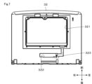
図7に示すように、支持部材32は、表示装置収容部321と、コネクタ収容部322と、ガイド溝323とを有する。表示装置収容部321は、支持部材32の中央部に設けられ、支持部材32を厚み方向に貫通する概ね矩形の開口である。表示装置収容部321は、内部に表示部171及び表示部171の動作を制御する基板172を収容する。表示部171は、第1面301側から視認可能に設置され、基板172は、表示部171の第2面302寄りつまり下方に設けられている。なお、表示部171と基板172とは、一体に構成されていても良いし、別体に構成されていても良い。 As shown in FIG. 7 , the support member 32 has a display device accommodation portion 321 , a connector accommodation portion 322 and a guide groove 323 . The display device accommodating portion 321 is provided in the central portion of the support member 32 and is a generally rectangular opening penetrating through the support member 32 in the thickness direction. The display device accommodating portion 321 accommodates therein the display portion 171 and the substrate 172 that controls the operation of the display portion 171 . The display unit 171 is installed so as to be visible from the first surface 301 side, and the substrate 172 is provided near the second surface 302 of the display unit 171, that is, below it. Note that the display unit 171 and the substrate 172 may be configured integrally or may be configured separately.

コネクタ収容部322は、表示装置収容部321よりも後方つまりヒンジ部303寄りに設けられている。コネクタ収容部322は、支持部材32を第2面302側から第1面301側に向かって窪ませた容器状に形成されている。本実施形態では、コネクタ収容部322は、左右方向に長い矩形に形成されている。コネクタ収容部322は、本体20から延びるリード線50と基板172から延びるリード線51とを接続するコネクタ53を内部に収容する。コネクタ収容部322とヒンジ部303とは接しておらず、前後方向に離れている。つまり、コネクタ収容部322とヒンジ部303との間には、前後方向に所定の距離を有する空間が設けられている。 The connector accommodating portion 322 is provided behind the display device accommodating portion 321 , that is, closer to the hinge portion 303 . The connector accommodating portion 322 is formed in a container shape by recessing the support member 32 from the second surface 302 side toward the first surface 301 side. In this embodiment, the connector accommodating portion 322 is formed in a rectangular shape elongated in the left-right direction. The connector accommodating portion 322 accommodates therein the connector 53 that connects the lead wire 50 extending from the main body 20 and the lead wire 51 extending from the substrate 172 . The connector accommodating portion 322 and the hinge portion 303 are not in contact with each other and are separated in the front-rear direction. That is, a space having a predetermined distance in the front-rear direction is provided between the connector accommodating portion 322 and the hinge portion 303 .

ガイド溝323は、支持部材32の第2面302寄りの面つまり下面に設けられており、リード線51を内部に収容しつつコネクタ収容部322から表示装置収容部321まで導く機能を有する。ガイド溝323は、支持部材32と一体に形成されている。本実施形態では、ガイド溝323は支持部材32の第2面302寄りの面を第1面301に向けて窪ませて形成されている。なお、ガイド溝323が第1面301に向けて窪ませて形成されているとは、支持部材32の第2面302寄りの面の大部分よりも底部が第1面301寄りに位置する溝形状を形成していることだけでなく、支持部材32の第2面302寄りの面から第2面302に向かって突出して形成された壁部によって囲まれることにより溝形状を形成していることも含まれる。 The guide groove 323 is provided on the surface of the support member 32 closer to the second surface 302 , ie, the lower surface, and has the function of accommodating the lead wire 51 inside and guiding it from the connector accommodating portion 322 to the display device accommodating portion 321 . The guide groove 323 is formed integrally with the support member 32 . In this embodiment, the guide groove 323 is formed by recessing the surface of the support member 32 closer to the second surface 302 toward the first surface 301 . It should be noted that the fact that the guide groove 323 is recessed toward the first surface 301 means that the bottom of the support member 32 is positioned closer to the first surface 301 than most of the surface of the support member 32 closer to the second surface 302 . In addition to forming a shape, a groove shape is formed by being surrounded by walls formed by protruding from the surface of the support member 32 closer to the second surface 302 toward the second surface 302 . is also included.

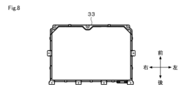
保持部材33は、概ね矩形の板状に形成されており、表示装置収容部321の開口を第2面302側から覆って表示装置収容部321の開口を開閉する。保持部材33は、表示装置収容部321に収容された表示装置17が支持部材32から脱落することを抑制する。本実施形態では、表示装置17は、予め保持部材33に装着されて、保持部材33を表示装置収容部321に装着することによって、蓋部材30に取り付けられる。 The holding member 33 is formed in a substantially rectangular plate shape, and covers the opening of the display device accommodating portion 321 from the second surface 302 side to open and close the opening of the display device accommodating portion 321 . The holding member 33 prevents the display device 17 housed in the display device housing portion 321 from dropping off from the support member 32 . In this embodiment, the display device 17 is attached to the holding member 33 in advance, and is attached to the lid member 30 by attaching the holding member 33 to the display device accommodating portion 321 .

メインカバー34は、図4、図6、及び図11等に示すように、支持部材32の第2面302側つまり下方に配置されて、蓋部材30の第2面302を形成する。図4、図9等に示すように、メインカバー34は、全体として矩形に形成され第1面301側つまり上方に向かって開口した浅い容器状に形成されている。メインカバー34を支持部材32に組み付けると、少なくとも表示装置収容部321が覆い隠される。本実施形態では、メインカバー34はコネクタ収容部322を覆っていない。この場合、メインカバー34は、切欠き部341を有している。切欠き部341は、メインカバー34の後部の一部を前方に向かって凹ませるように切り欠いて形成されている。切欠き部341は、メインカバー34の後部の左右方向の中央部であって、メインカバー34を支持部材32に組付けた際にコネクタ収容部322の外周部と概ね対応する位置に設けられている。なお、他の実施形態では、メインカバー34がコネクタ収容部322を覆う構成であっても良い。 The main cover 34 is arranged on the second surface 302 side of the support member 32, that is, below the support member 32, and forms the second surface 302 of the lid member 30, as shown in FIGS. As shown in FIGS. 4, 9, and the like, the main cover 34 is formed in a rectangular shape as a whole and is formed in a shallow container-like shape that opens toward the first surface 301 side, that is, upward. When the main cover 34 is attached to the support member 32, at least the display device accommodating portion 321 is covered. In this embodiment, the main cover 34 does not cover the connector accommodating portion 322 . In this case, the main cover 34 has a cutout portion 341 . The notch portion 341 is formed by notching a portion of the rear portion of the main cover 34 so as to recess forward. The notch portion 341 is provided at the central portion in the left-right direction of the rear portion of the main cover 34 and at a position substantially corresponding to the outer peripheral portion of the connector accommodating portion 322 when the main cover 34 is assembled to the support member 32 . there is In another embodiment, the main cover 34 may be configured to cover the connector accommodating portion 322 .

図10に示すように、ヒンジ部カバー35は、左右方向に長い矩形の板状に形成されており、少なくともヒンジ部303の第2面302側の面を形成する。つまり、ヒンジ部カバー35は、ヒンジ部303を第2面302側から覆う。本実施形態では、ヒンジ部カバー35は、コネクタ収容部322の開口を開閉する。メインカバー34とヒンジ部カバー35とは、共に蓋部材30の第2面302を形成するカバー部材を構成している。 As shown in FIG. 10 , the hinge section cover 35 is formed in a rectangular plate shape elongated in the left-right direction, and forms at least the second surface 302 side of the hinge section 303 . That is, the hinge section cover 35 covers the hinge section 303 from the second surface 302 side. In this embodiment, the hinge portion cover 35 opens and closes the opening of the connector accommodating portion 322 . The main cover 34 and the hinge cover 35 together constitute a cover member that forms the second surface 302 of the lid member 30 .

図11、12に示すように、ガイド溝323はカバー部材具体的にはメインカバー34によって第2面302側から覆われる。つまり、ガイド溝323の第2面寄りの開口は、メインカバー34によって覆われる。これにより、ガイド溝323の内部には液体や水蒸気が侵入し難くなる。そのため、リード線51を伝って液体が基板172やコネクタ53に到達することを抑制することができる。 As shown in FIGS. 11 and 12, the guide groove 323 is covered from the second surface 302 side by a cover member, specifically the main cover 34 . That is, the opening of the guide groove 323 near the second surface is covered with the main cover 34 . This makes it difficult for liquid or water vapor to enter the interior of the guide groove 323 . Therefore, it is possible to prevent the liquid from reaching the substrate 172 and the connector 53 along the lead wire 51 .

本実施形態では、ヒンジ部カバー35とメインカバー34とは、ヒンジ部カバー35の前部であってメインカバー34の後部において、この場合コネクタ収容部322の周囲において第1面301に垂直方向に関して重なっている。メインカバー34は、ヒンジ部カバー35と重なる後部において、第2面302側に段差を有している。つまり、メインカバー34は、ヒンジ部カバー35と重なる部分において、ヒンジ部カバー35を受け入れるように第1面301側に向かって窪んでいる。本実施形態では、メインカバー34は、後部においてヒンジ部カバー35の厚み分だけ窪んでおり、メインカバー34とヒンジ部カバー35とが支持部材32に装着された状態で、メインカバー34とヒンジ部カバー35との双方の第2面302側の面は、同一面上となるいわゆる面一の状態で配置される。これにより、カバー部材の概ね全体に亘って、同一の厚みを維持することができる。そのため、切欠き部341が形成されていても、カバー部材の強度が全体として概ね一定に保たれている。 In this embodiment, the hinge section cover 35 and the main cover 34 are arranged at the front section of the hinge section cover 35 and at the rear section of the main cover 34, in this case around the connector accommodating section 322, with respect to the direction perpendicular to the first surface 301. overlapping. The main cover 34 has a step on the second surface 302 side at the rear portion overlapping the hinge portion cover 35 . That is, the main cover 34 is recessed toward the first surface 301 so as to receive the hinge cover 35 at the portion overlapping the hinge cover 35 . In this embodiment, the main cover 34 is recessed at the rear portion by the thickness of the hinge section cover 35 , and when the main cover 34 and the hinge section cover 35 are attached to the support member 32 , the main cover 34 and the hinge section are recessed. The surfaces on the side of the second surface 302 on both sides of the cover 35 are arranged in a so-called flush state. Thereby, the same thickness can be maintained over substantially the entire cover member. Therefore, even if the notch portion 341 is formed, the strength of the cover member as a whole is kept generally constant.

ヒンジ部カバー35の左右方向の中央部には、開口部351が形成されている。開口部351は、ヒンジ部カバー35の後部を切り欠いて形成され、ヒンジ部カバー35とメインカバー34とを支持部材32に装着した状態で、開口部351によって蓋部材30の内部と外部とが連通する。 An opening 351 is formed in the central portion of the hinge portion cover 35 in the left-right direction. The opening 351 is formed by cutting out the rear portion of the hinge portion cover 35 , and when the hinge portion cover 35 and the main cover 34 are attached to the support member 32 , the opening 351 separates the inside and the outside of the lid member 30 . communicate.

ヒンジ部カバー35によってコネクタ収容部322を覆った状態つまりヒンジ部カバー35を支持部材32及びメインカバー34に装着した状態で、ヒンジ部カバー35とコネクタ収容部322の開口部との間には隙間が設けられている。この隙間は、リード線50、51がコネクタ収容部322内部に引き込まれ又は引き出される空間となる。つまり、ヒンジ部カバー35の内側表面すなわち第1面301側の表面と、コネクタ収容部322の開口部とは、第1面301に垂直な方向に関して所定距離離れている。この所定距離は、リード線50、51を通すことができればよく、例えば1mm~5mmの範囲内に設定することができる。 With the connector housing portion 322 covered by the hinge portion cover 35, that is, with the hinge portion cover 35 attached to the support member 32 and the main cover 34, there is a gap between the hinge portion cover 35 and the opening of the connector housing portion 322. is provided. This gap serves as a space through which the lead wires 50 and 51 are drawn into or drawn out from inside the connector accommodating portion 322 . That is, the inner surface of the hinge cover 35 , that is, the surface on the side of the first surface 301 and the opening of the connector accommodating portion 322 are separated from each other by a predetermined distance in the direction perpendicular to the first surface 301 . This predetermined distance is sufficient as long as the lead wires 50 and 51 can be passed through, and can be set within a range of 1 mm to 5 mm, for example.

蓋部材30は、更に連結部材36を有する。連結部材36は、ヒンジ部303において、ヒンジ部カバー35の開口部にはまり込むように位置している。連結部材36は、トップカバー22のヒンジ受部223の中央部に回動不可能に支持されて、支持部材32やメインカバー34、ヒンジ部カバー35に対しては回動可能に設けられている。連結部材36は、トップカバー22と、蓋部材30とを連結する機能を有する。詳細は図示しないが、連結部材36は、後部と右側面とに内部をリード線50が通過可能に連通下開口部を有している。 The lid member 30 further has a connecting member 36 . The connecting member 36 is positioned at the hinge portion 303 so as to fit into the opening of the hinge portion cover 35 . The connecting member 36 is non-rotatably supported at the central portion of the hinge receiving portion 223 of the top cover 22, and is rotatably provided with respect to the supporting member 32, the main cover 34, and the hinge portion cover 35. . The connecting member 36 has a function of connecting the top cover 22 and the lid member 30 . Although details are not shown, the connecting member 36 has lower communicating openings in the rear portion and the right side surface through which the lead wires 50 can pass.

リード線50、51は、本体20内部に設けられた制御装置と表示装置17より具体的には基板172とを電気的に接続する。図12を参照して、本体20から基板172まで延びるリード線50、51の配設方法を説明する。リード線50は、本体20からヒンジ部303を通って蓋部材30に導かれる。この場合、リード線50は連結部材36と、ヒンジ部カバー35の開口部351とを通ってカバー部材の内側に引き込まれる。 The lead wires 50 , 51 electrically connect the control device provided inside the main body 20 and the display device 17 , more specifically, the substrate 172 . A method of disposing lead wires 50 and 51 extending from main body 20 to substrate 172 will be described with reference to FIG. The lead wire 50 is led from the main body 20 to the lid member 30 through the hinge portion 303 . In this case, the lead wire 50 is drawn inside the cover member through the connecting member 36 and the opening 351 of the hinge section cover 35 .

リード線50は、ヒンジ部カバー35の内側つまり第1面301寄りにおいて、直接前方に設けられたコネクタ収容部322に向けて延びてはいない。つまり、リード線50は、まず左右方向この場合右方に引き回されて、メインカバー34の後部に設けられたガイド部342によって向きを変えられて前方に向かう。ガイド部342は、リード線50の向きを変えてリード線50を屈曲させる機能を有する。本実施形態では、ガイド部342は、ヒンジ部303において切欠き部341を後方に延長した領域、この場合切欠き部341の右端部を後方に延長した領域に設けられている。ガイド部342は、メインカバー34から第2面302側に突出して第1面301に垂直な方向に延びる軸部と、軸部の第2面302側の先端部から第1面301に水平な方向に延びる爪部とを有する。爪部は、軸部の周囲を引き回されるリード線50が、ガイド部342から脱落することを抑制する機能を有する。 The lead wire 50 does not extend toward the connector accommodating portion 322 provided directly in front of the inside of the hinge portion cover 35, that is, near the first surface 301. As shown in FIG. In other words, the lead wire 50 is first routed in the left-right direction, in this case rightward, and then turned forward by the guide portion 342 provided at the rear portion of the main cover 34 . The guide portion 342 has a function of bending the lead wire 50 by changing the direction of the lead wire 50 . In the present embodiment, the guide portion 342 is provided in a rearwardly extending region of the notch portion 341 in the hinge portion 303 , in this case, a rearwardly extending region of the right end portion of the notch portion 341 . The guide portion 342 includes a shaft portion that protrudes from the main cover 34 toward the second surface 302 and extends in a direction perpendicular to the first surface 301 , and a guide portion that extends horizontally from the tip of the shaft portion on the second surface 302 side to the first surface 301 . and a claw portion extending in the direction. The claw portion has a function of preventing the lead wire 50 routed around the shaft portion from falling off from the guide portion 342 .

リード線50は、ガイド部342の周囲を回ってこの場合概ね270°向きを変えて前方のコネクタ収容部322に向けて進む。コネクタ収容部322に至ったリード線50は、左右方向この場合左方へ向きを変えて、左右方向に長いコネクタ収容部322内部を進み、コネクタ53に接続される。例えば、リード線50のコネクタ53に接続される先端部は雄側コネクタ501であり、コネクタ53は雌型コネクタである。コネクタ53のリード線50との接続側に対する反対側からは、リード線51が延びている。 The lead wire 50 turns around the guide portion 342 , in this case approximately 270°, and advances toward the connector receiving portion 322 in the front. The lead wire 50 reaching the connector accommodating portion 322 changes its direction in the left-right direction, in this case leftward, travels inside the connector accommodating portion 322 that is elongated in the left-right direction, and is connected to the connector 53 . For example, the tip of the lead wire 50 connected to the connector 53 is the male connector 501, and the connector 53 is a female connector. A lead wire 51 extends from the side of the connector 53 opposite to the side connected to the lead wire 50 .

リード線51は、コネクタ53から左右方向この場合左方に向かって延びて、コネクタ収容部322の外部に出る。コネクタ収容部322の外に出たリード線51は、メインカバー34の内側つまり第1面301寄りを更に左方に向かって延びる。リード線51は、支持部材32の第2面302寄りの面つまり下面に設けられたガイド溝323によって基板172まで導かれる。ガイド溝323は、コネクタ収容部322の左方から更に左方に向けて延びて、基板172の左辺を後方に延長させた領域よりも右側で方向を変えて前方に向けて延びる。すなわち、リード線51は、コネクタ収容部322から左方に延び、方向を転換して前方に向かって延びて、基板172の後部左寄り部分に接続される。 The lead wire 51 extends from the connector 53 in the left-right direction, in this case, leftward, and exits the connector accommodating portion 322 . The lead wire 51 outside the connector accommodating portion 322 extends leftward inside the main cover 34, that is, near the first surface 301. As shown in FIG. The lead wire 51 is guided to the substrate 172 by a guide groove 323 provided on the surface of the support member 32 closer to the second surface 302 , that is, the lower surface. The guide groove 323 extends further leftward from the left side of the connector housing portion 322, changes its direction on the right side of the area where the left side of the board 172 is extended rearward, and extends forward. That is, the lead wire 51 extends leftward from the connector accommodating portion 322 , changes its direction, extends forward, and is connected to the rear left portion of the board 172 .

蓋部材30は、更に、図13~図16に示すように、防水構造を有する。防水構造は、少なくともコネクタ53及び又コネクタ53の周辺への液体や水蒸気の侵入を低減する機能を有する。例えば、防水構造は、防水性能を有する防水部材によって、コネクタ53やコネクタ53の周辺の構成を覆うことによって実現することができる。なお、図13~図16以外の図では、防水構造の図示は省略されている。 The lid member 30 further has a waterproof structure, as shown in FIGS. 13-16. The waterproof structure has a function of reducing penetration of liquid or water vapor into at least the connector 53 and/or the periphery of the connector 53 . For example, the waterproof structure can be realized by covering the connector 53 and the configuration around the connector 53 with a waterproof member having waterproof performance. It should be noted that illustration of the waterproof structure is omitted in figures other than FIGS.

一の実施形態では、蓋部材30は、図13に網掛けで示すように、防水部材60を有する。防水部材60は、コネクタ収容部322の開口部を密封する。例えば、防水部材60は、コネクタ収容部322の開口部とヒンジ部カバー35との間に配置されて、コネクタ収容部322内部を密封する。これにより、コネクタ収容部322内部に液体や水蒸気が侵入することを抑制して、コネクタ53の内部に液体や水蒸気が到達することを抑制する。防水部材60は、防水性、柔軟性及び伸縮性を有する例えば合成又は天然ゴムで形成されたパッキンやクッション材である。この場合、防水部材60は、例えばコネクタ収容部322の開口部の外形つまり中央部が開口した枠状に形成されてもよい。他の実施形態では、図14に網掛けで示すように、蓋部材30は、コネクタ収容部322の全体を覆う形状この場合矩形に形成された防水部材70を有していてもよい。 In one embodiment, the lid member 30 has a waterproof member 60 as shown by shading in FIG. The waterproof member 60 seals the opening of the connector accommodating portion 322 . For example, the waterproof member 60 is arranged between the opening of the connector accommodating portion 322 and the hinge portion cover 35 to seal the inside of the connector accommodating portion 322 . As a result, liquid and steam are prevented from entering the interior of the connector accommodating portion 322 and are prevented from reaching the interior of the connector 53 . The waterproof member 60 is a waterproof, flexible and stretchable packing or cushioning material made of, for example, synthetic or natural rubber. In this case, the waterproof member 60 may be formed, for example, in the shape of a frame with an opening in the outer shape of the opening of the connector accommodating portion 322, that is, in the central portion. In another embodiment, as shown by hatching in FIG. 14, the lid member 30 may have a waterproof member 70 formed in a rectangular shape, in this case, covering the entire connector accommodating portion 322 .

一の実施形態では、図15に示すように、蓋部材30は防水部材61を有する。防水部材61は、コネクタ53の表面を直接又は間接的に被覆する。防水部材61は、例えばコネクタ53の周囲を巻回して密封する。これにより、コネクタ53を被覆することで、コネクタ53の内部に外部から液体や水蒸気が侵入することを抑制する。防水部材61は、防水性、伸縮性及び柔軟性を有するシート状又はテープ状の部材であり、例えば合成樹脂で形成されている。他の実施形態では、防水部材61は、防水性及び柔軟性を有する袋状の部材であり、内部にコネクタ53を封入する。 In one embodiment, the lid member 30 has a waterproof member 61 as shown in FIG. The waterproof member 61 directly or indirectly covers the surface of the connector 53 . The waterproof member 61 is, for example, wrapped around the connector 53 to seal it. Thus, by covering the connector 53, it is possible to prevent liquid or water vapor from entering the connector 53 from the outside. The waterproof member 61 is a sheet-like or tape-like member having waterproofness, elasticity, and flexibility, and is made of synthetic resin, for example. In another embodiment, the waterproof member 61 is a bag-like member having waterproof and flexibility, and encloses the connector 53 inside.

一の実施形態では、図16に示すように蓋部材30は防水部材62を有する。防水部材62は、直接又は間接的にリード線50及び又はリード線51を包む。これにより、リード線50及び又はリード線51に液体や水蒸気が付着することを抑制すると共に、リード線50及び又はリード線51の表面を伝ってコネクタ53の内部に液体や水蒸気が侵入することを抑制する。防水部材62は、例えば合成樹脂で形成された防水性であって、粘着性又は非粘着性のテープである。防水部材62は、リード線50、51の表面に巻き付けることができる。他の実施形態では、防水部材62は、例えば防水性及び柔軟性を有するチューブ状部材である。防水部材62は、例えば、合成樹脂で形成されたいわゆる絶縁チューブである。なお、リード線50及び又はリード線51の表面を絶縁チューブで覆った後に、更に防水性のテープを巻き付けて防水部材62としてもよい。 In one embodiment, the lid member 30 has a waterproof member 62 as shown in FIG. The waterproof member 62 directly or indirectly wraps the lead wires 50 and/or the lead wires 51 . This prevents the liquid or water vapor from adhering to the lead wire 50 and/or the lead wire 51, and prevents the liquid or water vapor from entering the connector 53 along the surface of the lead wire 50 and/or the lead wire 51. Suppress. The waterproof member 62 is, for example, a waterproof, adhesive or non-adhesive tape made of synthetic resin. The waterproof member 62 can be wrapped around the surfaces of the lead wires 50 and 51 . In another embodiment, the waterproof member 62 is, for example, a waterproof flexible tubular member. The waterproof member 62 is, for example, a so-called insulating tube made of synthetic resin. Note that the waterproof member 62 may be formed by wrapping the lead wire 50 and/or the lead wire 51 with an insulating tube and then winding a waterproof tape thereon.

防水部材60若しくは70、61又は62は、それぞれ単独で使用しても良いし、2以上を組み合わせて使用しても良い。本実施形態では、蓋部材30は防水部材60、61、及び62をいずれも含んで構成されている。 The waterproof member 60 or 70, 61 or 62 may be used alone or in combination of two or more. In this embodiment, the lid member 30 is configured including all of the waterproof members 60 , 61 and 62 .

ここで、洗濯機10の運転には水や洗濯処理剤などの液体が使用される。また、温水や乾燥機能を使用した場合には、本体20内部に水蒸気が発生する。一方、本体20から蓋部材30内部にリード線50が引き込まれるためには、蓋部材30にリード線50を通す開口が必要となる。この場合、本体20内部において防水性を高めていても、蓋部材30の内部とりわけ通電されるリード線50、51やコネクタ53の防水性が低いと、開口から侵入した液体や水蒸気などによって、漏電などの虞がゼロではない。 Here, a liquid such as water or a laundry treatment agent is used to operate the washing machine 10 . Also, when the hot water or drying function is used, water vapor is generated inside the main body 20 . On the other hand, in order to draw the lead wire 50 from the main body 20 into the lid member 30 , an opening for passing the lead wire 50 is required in the lid member 30 . In this case, even if the inside of the main body 20 is highly waterproof, if the inside of the lid member 30, especially the lead wires 50, 51 and the connector 53, which are electrically energized, are low in waterproofness, liquid or water vapor entering from the opening may cause electric leakage. The risk of such things is not zero.

以上説明した本実施形態によれば、衣類処理装置としての洗濯機10は、本体20と、蓋部材30と、表示装置17と、コネクタ53と、を備える。本体20は、上方に向けて開口した本体開口部221を有する。蓋部材30は、本体20の上部に回動可能に支持されて本体開口部221を開閉し、本体20の外側を向いた第1面301と、第1面301に対向して本体開口部221側を向いた第2面302と、回動軸Axが位置するヒンジ部303と、を有する。表示装置17は、蓋部材30の内部に設けられて第1面301側から視認可能に情報を表示する。コネクタ53は、表示装置17に接続されたリード線51と、本体20から延びるリード線50と、を接続する。蓋部材30は、コネクタ収容部322と、カバー部材を構成するメインカバー34及びヒンジ部カバー35と、を有する。コネクタ収容部322は、内部にコネクタ53を収容する。メインカバー34及び又はヒンジ部カバー35は、コネクタ収容部322を覆う。 According to the embodiment described above, the washing machine 10 as the clothes processing apparatus includes the main body 20 , the lid member 30 , the display device 17 and the connector 53 . The body 20 has a body opening 221 that opens upward. The lid member 30 is rotatably supported on the upper portion of the main body 20 to open and close the main body opening 221 , and has a first surface 301 facing the outside of the main body 20 and a main body opening 221 facing the first surface 301 . It has a second surface 302 facing the side and a hinge portion 303 on which the pivot axis Ax is located. The display device 17 is provided inside the lid member 30 and displays information so that it can be visually recognized from the first surface 301 side. The connector 53 connects the lead wire 51 connected to the display device 17 and the lead wire 50 extending from the main body 20 . The lid member 30 has a connector accommodating portion 322, and a main cover 34 and a hinge portion cover 35 that constitute cover members. The connector accommodating portion 322 accommodates the connector 53 therein. The main cover 34 and/or the hinge portion cover 35 cover the connector accommodating portion 322 .

これによれば、蓋部材30の内部において液体や水蒸気が侵入した際に漏電のリスクのあるコネクタ53は、カバー部材によって保護される。そのため、コネクタ53に液体や水蒸気が侵入することを抑制できる。したがって、防水性に優れた蓋を備えた衣類処理装置が提供される。 According to this, the connector 53, which has a risk of electric leakage when liquid or water vapor enters inside the lid member 30, is protected by the cover member. Therefore, it is possible to prevent liquid and water vapor from entering the connector 53 . Accordingly, there is provided a clothes processing apparatus having a lid with excellent waterproofness.

更に、蓋部材30は、防水部材としての防水部材60、61、62を備える。防水構造は、リード線50、51及びコネクタ53の少なくともいずれか一方への液体又は水蒸気の侵入を防ぐ。これによれば、蓋部材30の内部において漏電のリスクのあるリード線50、51及び又はコネクタ53は、防水構造によって保護される。したがって、防水性に優れた蓋を備えた衣類処理装置が提供される。 Furthermore, the lid member 30 includes waterproof members 60, 61, and 62 as waterproof members. The waterproof structure prevents liquid or water vapor from entering the leads 50 , 51 and/or the connector 53 . According to this, the lead wires 50, 51 and/or the connector 53, which are at risk of electric leakage inside the lid member 30, are protected by the waterproof structure. Accordingly, there is provided a clothes processing apparatus having a lid with excellent waterproofness.

蓋部材30は、リード線50の少なくともコネクタ53に接続される部分からヒンジ部303を通過する部分までを包んでいる防水部材62を有する。 The lid member 30 has a waterproof member 62 covering at least the portion of the lead wire 50 connected to the connector 53 to the portion passing through the hinge portion 303 .

これによれば、ヒンジ部カバー35の開口部351において、外部への露出の可能性があり、液体や水蒸気への露出の可能性が高くなりがちなリード線50自体への液体や水蒸気の侵入を抑制することができる。更に、液体や水蒸気がリード線50の表面を伝ってコネクタ53に到達することを抑制することができる。したがって、蓋部材30の防水性が向上した衣類処理装置が提供される。 According to this, at the opening 351 of the hinge part cover 35, there is a possibility of exposure to the outside, and the possibility of exposure to liquid and water vapor tends to increase, so liquid and water vapor can enter the lead wire 50 itself. can be suppressed. Furthermore, it is possible to prevent liquid or water vapor from reaching the connector 53 along the surface of the lead wire 50 . Therefore, a clothes processing apparatus in which the lid member 30 is improved in waterproofness is provided.

蓋部材30は、表示装置17とコネクタ53とを接続するリード線51を被覆する防水部材62を有する。 The lid member 30 has a waterproof member 62 covering the lead wire 51 connecting the display device 17 and the connector 53 .

これによれば、液体や水蒸気がリード線51を伝って基板172まで到達することが抑制される。したがって、蓋部材30の防水性が向上した衣類処理装置が提供される。 According to this, liquid or water vapor is prevented from reaching the substrate 172 along the lead wire 51 . Therefore, a clothes processing apparatus in which the lid member 30 is improved in waterproofness is provided.

コネクタ収容部322は蓋部材30この場合支持部材32の第2面302側から第1面301側に向かって窪ませて形成されている。蓋部材30は、ヒンジ部カバー35によってコネクタ収容部322が覆われた状態においてコネクタ収容部322の開口部とカバー部材この場合ヒンジ部カバー35との間の隙間を埋めるように配置される前記防水部材を有する。 The connector accommodating portion 322 is formed by recessing from the second surface 302 side of the cover member 30 (in this case, the support member 32) toward the first surface 301 side. The lid member 30 is arranged to fill the gap between the opening of the connector accommodating portion 322 and the cover member, in this case, the hinge portion cover 35 in a state where the connector accommodating portion 322 is covered with the hinge portion cover 35. have members.

これによれば、コネクタ収容部322外部からの液体又は水蒸気の侵入を抑制することができる。したがって、蓋部材30の防水性が向上した衣類処理装置が提供される。 According to this, intrusion of liquid or water vapor from the outside of the connector accommodating portion 322 can be suppressed. Therefore, a clothes processing apparatus in which the lid member 30 is improved in waterproofness is provided.

蓋部材30は、コネクタ53を包み込む防水部材61を有する。この場合、例えば防水部材61は、防水性のシート状の部材であってコネクタ53を巻回してもよいし、防水性の袋状の部材であってコネクタ53を封入してもよい。 The lid member 30 has a waterproof member 61 that wraps around the connector 53 . In this case, for example, the waterproof member 61 may be a waterproof sheet-like member around which the connector 53 is wound, or may be a waterproof bag-like member that encloses the connector 53 .

これによれば、仮にコネクタ収容部322内部に液体や水蒸気が侵入してしまったとしても、コネクタ53の内部まで液体や水蒸気が侵入することを抑制することができる。したがって、蓋部材30の防水性が向上した衣類処理装置が提供される。 According to this, even if liquid or water vapor enters the inside of the connector accommodating portion 322 , it is possible to suppress the liquid or water vapor from entering the inside of the connector 53 . Therefore, a clothes processing apparatus in which the lid member 30 is improved in waterproofness is provided.

コネクタ収容部322とヒンジ部303との間には、蓋部材30が閉じた閉鎖状態において前後方向に関して空間が形成される。つまり、コネクタ収容部322とヒンジ部303とは、第1面301に垂直な方向に関して互いに離れている。 A space is formed in the front-rear direction between the connector accommodating portion 322 and the hinge portion 303 in the closed state in which the lid member 30 is closed. That is, the connector housing portion 322 and the hinge portion 303 are separated from each other in the direction perpendicular to the first surface 301 .

これによれば、コネクタ収容部322を、開口部351が設けられたヒンジ部303から離して配置することにより、開口部351を介して液体や水蒸気がコネクタ53の内部に侵入することを抑制することができる。したがって、蓋部材30の防水性が向上した衣類処理装置が提供される。 According to this, by arranging the connector accommodating portion 322 away from the hinge portion 303 provided with the opening 351, it is possible to prevent liquid or water vapor from entering the connector 53 through the opening 351. be able to. Therefore, a clothes processing apparatus in which the lid member 30 is improved in waterproofness is provided.

リード線50、51は、リード線50のヒンジ部303を通る部分から、リード線51の表示装置17この場合基板172との接続部までが、一直線上にない。つまり、リード線50、51は、開口部351から基板172との接続部まで、少なくとも一度屈曲している。 The lead wires 50 and 51 are not on a straight line from the portion of the lead wire 50 passing through the hinge portion 303 to the connection portion of the lead wire 51 to the display device 17 , in this case the substrate 172 . That is, the lead wires 50 and 51 are bent at least once from the opening 351 to the connecting portion with the substrate 172 .

これによれば、リード線50、51を屈曲した形状とすることで、蓋部材30の閉鎖状態では、仮に液体がリード線50,51を伝って流れ落ちても最下点であるリード線50、51の屈曲部に溜まり、その先の基板172との接続部まで伝い難くなる。また、蓋部材30が開いた開放状態においては、水蒸気がリード線50、51の周囲を直線的に上昇して基板172まで到達し難くなる。そのため、基板172との接続部や基板172に液体や水蒸気が侵入することを抑制することができる。したがって、蓋部材30の防水性が向上した衣類処理装置が提供される。 According to this, by forming the lead wires 50 and 51 into a bent shape, even if the liquid flows down along the lead wires 50 and 51 in the closed state of the cover member 30, the lead wires 50 and 51, which are the lowest points, It accumulates at the bent portion of 51 and becomes difficult to reach the connection portion with the substrate 172 beyond it. Further, in the open state where the lid member 30 is open, it is difficult for water vapor to linearly rise around the lead wires 50 and 51 and reach the substrate 172 . Therefore, it is possible to suppress penetration of liquid and water vapor into the connection portion with the substrate 172 and the substrate 172 . Therefore, a clothes processing apparatus in which the lid member 30 is improved in waterproofness is provided.

なお、上記各実施形態は、相互に組み合わせることができる。また、2以上の実施形態の特徴部分のみを抽出して組み合わせることもできる。上記実施形態は、例として提示したものであり、発明の範囲を限定することは意図していない。これら新規な実施形態は、その他の様々な形態で実施されることが可能であり、発明の要旨を逸脱しない範囲で、種々の省略、置き換え、変更を行うことができる。本実施形態及びその変形は、発明の範囲及び要旨に含まれると共に、特許請求の範囲に記載された発明とその均等の範囲に含まれる。 Note that the above embodiments can be combined with each other. It is also possible to extract and combine only characteristic portions of two or more embodiments. The above embodiments are presented as examples and are not intended to limit the scope of the invention. These novel embodiments can be implemented in various other forms, and various omissions, replacements, and modifications can be made without departing from the scope of the invention. This embodiment and its modifications are included in the scope and gist of the invention, and are included in the scope of the invention described in the claims and its equivalents.

10…洗濯機、11…水槽(洗濯槽)、12…回転槽(洗濯槽)、17…表示装置、171…表示部、172…基板、20…本体、30…蓋部材、301…第1面、302…第2面、303…ヒンジ部、31…板部材、32…支持部材、表示装置収容部321、コネクタ収容部、33…基板保持部材、34…メインカバー、35…ヒンジ部カバー、50,51…リード線、53…コネクタ、60,61,62…防水部材、70…防水部材、Ax…回動軸 DESCRIPTION OF SYMBOLS 10... Washing machine, 11... Water tank (washing tub), 12... Rotating tub (washing tub), 17... Display device, 171... Display part, 172... Substrate, 20... Main body, 30... Lid member, 301... First surface , 302... Second surface 303... Hinge part 31... Plate member 32... Support member, display device accommodating part 321, connector accommodating part 33... Board holding member 34... Main cover 35... Hinge part cover 50 , 51... Lead wire, 53... Connector, 60, 61, 62... Waterproof member, 70... Waterproof member, Ax... Rotating shaft

Claims (7)

上方に向けて開口した本体開口部を有する本体と、
前記本体の上部に回動可能に支持されて前記本体開口部を開閉し、前記本体の外側を向いた第1面と、前記第1面に対向して前記本体開口部側を向いた第2面と、回動軸が位置するヒンジ部と、を有する蓋部材と、
前記蓋部材の内部に設けられて前記第1面側から視認可能に情報を表示する表示装置と、
前記表示装置に接続されたリード線と、前記本体から延びるリード線と、を接続するコネクタと、を備え、
前記蓋部材は、
内部に前記コネクタを収容するコネクタ収容部と、
前記コネクタ収容部を覆うカバー部材と、を有する
衣類処理装置。
a main body having a main body opening that opens upward;
A first surface facing the outside of the main body and a second surface facing the main body opening facing the first surface are rotatably supported on the upper part of the main body to open and close the main body opening. a lid member having a surface and a hinge portion on which the pivot shaft is located;
a display device provided inside the lid member for displaying information so as to be visible from the first surface side;
a connector for connecting a lead wire connected to the display device and a lead wire extending from the main body,
The lid member is
a connector accommodating portion that accommodates the connector therein;
and a cover member that covers the connector accommodating portion.
前記蓋部材は、前記リード線の前記コネクタに接続される部分から前記ヒンジ部を通過する部分までを包んでいる防水部材を有する
請求項1に記載の衣類処理装置。
2. The laundry processing apparatus according to claim 1, wherein the cover member has a waterproof member covering a portion of the lead wire connected to the connector and a portion passing through the hinge portion.
前記蓋部材は、前記表示装置と前記コネクタとを接続する前記リード線を被覆する防水部材を有する
請求項1又は2に記載の衣類処理装置。
3. The laundry processing apparatus according to claim 1, wherein the lid member has a waterproof member covering the lead wire connecting the display device and the connector.
前記コネクタ収容部は前記蓋部材の前記第2面側から前記第1面側に向かって窪ませて形成されており、
前記蓋部材は、前記カバー部材によってコネクタ収容部322が覆われた状態において前記コネクタ収容部の開口部と前記カバー部材との間の隙間を埋めるように配置される防水部材を有する、
請求項1から3のいずれか一項に記載の衣類処理装置。
The connector accommodating portion is formed by being recessed from the second surface side of the lid member toward the first surface side,
The lid member has a waterproof member arranged to fill a gap between the opening of the connector housing portion and the cover member in a state where the connector housing portion 322 is covered with the cover member.
4. A clothing processing apparatus according to any one of claims 1-3.
前記蓋部材は、前記コネクタを包み込む防水部材を有する
請求項1から4のいずれか一項に記載の衣類処理装置。
The laundry processing apparatus according to any one of claims 1 to 4, wherein the lid member has a waterproof member that encloses the connector.
前記コネクタ収容部と前記ヒンジ部との間には、前記蓋部材が閉じた閉鎖状態において前後方向に関して空間が形成される
請求項1から5のいずれか一項に記載の衣類処理装置。
The laundry processing apparatus according to any one of claims 1 to 5, wherein a space is formed between the connector accommodating portion and the hinge portion in the front-rear direction in a closed state in which the lid member is closed.
前記リード線は、前記ヒンジ部を通る部分から前記表示装置との接続部までが、一直線上にない
請求項1から6のいずれか一項に記載の衣類処理装置。
The laundry processing apparatus according to any one of claims 1 to 6, wherein a portion of the lead wire from a portion passing through the hinge portion to a connection portion with the display device is not in a straight line.
JP2021166270A 2021-10-08 2021-10-08 Clothes Processing Equipment Active JP7623262B2 (en)

Priority Applications (2)

Application Number Priority Date Filing Date Title
JP2021166270A JP7623262B2 (en) 2021-10-08 2021-10-08 Clothes Processing Equipment
CN202211088135.9A CN115948899A (en) 2021-10-08 2022-09-07 Clothes treatment device

Applications Claiming Priority (1)

Application Number Priority Date Filing Date Title
JP2021166270A JP7623262B2 (en) 2021-10-08 2021-10-08 Clothes Processing Equipment

Publications (2)

Publication Number Publication Date
JP2023056830A true JP2023056830A (en) 2023-04-20
JP7623262B2 JP7623262B2 (en) 2025-01-28

Family

ID=85907311

Family Applications (1)

Application Number Title Priority Date Filing Date
JP2021166270A Active JP7623262B2 (en) 2021-10-08 2021-10-08 Clothes Processing Equipment

Country Status (2)

Country Link
JP (1) JP7623262B2 (en)
CN (1) CN115948899A (en)

Citations (7)

* Cited by examiner, † Cited by third party
Publication number Priority date Publication date Assignee Title
JPS4922775U (en) * 1972-05-31 1974-02-26
JPH05168794A (en) * 1991-12-26 1993-07-02 Toshiba Corp Dehydrating/washing machine
JP2012095152A (en) * 2010-10-27 2012-05-17 Nec Corp Portable electronic device
JP2017068942A (en) * 2015-09-29 2017-04-06 ミハル通信株式会社 Waterproof boot adapter and relay parts covering structure
JP2017205436A (en) * 2016-05-20 2017-11-24 有限会社近藤研究所 Curved pipe for endoscope
CN107723998A (en) * 2016-08-11 2018-02-23 青岛海尔洗衣机有限公司 A kind of cabling pin shaft structure and washing machine
JP2019177226A (en) * 2019-07-19 2019-10-17 パナソニックIpマネジメント株式会社 Drum-type washing machine

Family Cites Families (3)

* Cited by examiner, † Cited by third party
Publication number Priority date Publication date Assignee Title
JP4624212B2 (en) * 2005-08-24 2011-02-02 三洋電機株式会社 Washing machine
JP5349424B2 (en) * 2010-08-23 2013-11-20 株式会社東芝 Washing machine
JP2017064286A (en) * 2015-10-02 2017-04-06 パナソニックIpマネジメント株式会社 Washing machine

Patent Citations (7)

* Cited by examiner, † Cited by third party
Publication number Priority date Publication date Assignee Title
JPS4922775U (en) * 1972-05-31 1974-02-26
JPH05168794A (en) * 1991-12-26 1993-07-02 Toshiba Corp Dehydrating/washing machine
JP2012095152A (en) * 2010-10-27 2012-05-17 Nec Corp Portable electronic device
JP2017068942A (en) * 2015-09-29 2017-04-06 ミハル通信株式会社 Waterproof boot adapter and relay parts covering structure
JP2017205436A (en) * 2016-05-20 2017-11-24 有限会社近藤研究所 Curved pipe for endoscope
CN107723998A (en) * 2016-08-11 2018-02-23 青岛海尔洗衣机有限公司 A kind of cabling pin shaft structure and washing machine
JP2019177226A (en) * 2019-07-19 2019-10-17 パナソニックIpマネジメント株式会社 Drum-type washing machine

Also Published As

Publication number Publication date
CN115948899A (en) 2023-04-11
JP7623262B2 (en) 2025-01-28

Similar Documents

Publication Publication Date Title
KR101880083B1 (en) Washing machine
CN112921590B (en) Washing machine
KR102537237B1 (en) Washing machine
US8800325B2 (en) Washing machine
JP2024026546A (en) Garment processing equipment door structure
KR102620364B1 (en) Washing machine
KR102647316B1 (en) Washing machine
JP6378940B2 (en) Drum washing machine
JP2023056830A (en) clothing processing equipment
KR20140131809A (en) Detergent automatic providing apparatus and washing machine having the same
JP4624212B2 (en) Washing machine
KR101963249B1 (en) Washing machine
KR102878527B1 (en) Washing machine
KR102320194B1 (en) Washing machine
WO2023199713A1 (en) Washing machine
JP2022167524A (en) clothing processing equipment
JP7732834B2 (en) Clothes treatment equipment
JP2016158746A (en) dishwasher
KR102912959B1 (en) Apparatus for treating laundry
JP2023179990A (en) clothing processing equipment
KR101568038B1 (en) Washing machine
JP2024043722A (en) Clothes Processing Equipment
JP2024174142A (en) washing machine
KR20230001299A (en) Laundry treating apparatus
JPS602291A (en) Washer

Legal Events

Date Code Title Description
A621 Written request for application examination

Free format text: JAPANESE INTERMEDIATE CODE: A621

Effective date: 20240405

A977 Report on retrieval

Free format text: JAPANESE INTERMEDIATE CODE: A971007

Effective date: 20240925

A131 Notification of reasons for refusal

Free format text: JAPANESE INTERMEDIATE CODE: A131

Effective date: 20241008

A521 Request for written amendment filed

Free format text: JAPANESE INTERMEDIATE CODE: A523

Effective date: 20241206

TRDD Decision of grant or rejection written
A01 Written decision to grant a patent or to grant a registration (utility model)

Free format text: JAPANESE INTERMEDIATE CODE: A01

Effective date: 20241224

A61 First payment of annual fees (during grant procedure)

Free format text: JAPANESE INTERMEDIATE CODE: A61

Effective date: 20250116

R150 Certificate of patent or registration of utility model

Ref document number: 7623262

Country of ref document: JP

Free format text: JAPANESE INTERMEDIATE CODE: R150

S111 Request for change of ownership or part of ownership

Free format text: JAPANESE INTERMEDIATE CODE: R313113

R350 Written notification of registration of transfer

Free format text: JAPANESE INTERMEDIATE CODE: R350