JP2024123741A - PRINTING SYSTEM, PRINTING APPARATUS, PRINTING SYSTEM CONTROL METHOD, PRINTING APPARATUS CONTROL METHOD, AND PROGRAM - Google Patents
PRINTING SYSTEM, PRINTING APPARATUS, PRINTING SYSTEM CONTROL METHOD, PRINTING APPARATUS CONTROL METHOD, AND PROGRAM Download PDFInfo
- Publication number
- JP2024123741A JP2024123741A JP2023031383A JP2023031383A JP2024123741A JP 2024123741 A JP2024123741 A JP 2024123741A JP 2023031383 A JP2023031383 A JP 2023031383A JP 2023031383 A JP2023031383 A JP 2023031383A JP 2024123741 A JP2024123741 A JP 2024123741A
- Authority
- JP
- Japan
- Prior art keywords
- static elimination
- sheet
- printing
- jam
- user
- Prior art date
- Legal status (The legal status is an assumption and is not a legal conclusion. Google has not performed a legal analysis and makes no representation as to the accuracy of the status listed.)
- Pending
Links
Images


Classifications
-
- B—PERFORMING OPERATIONS; TRANSPORTING
- B41—PRINTING; LINING MACHINES; TYPEWRITERS; STAMPS
- B41J—TYPEWRITERS; SELECTIVE PRINTING MECHANISMS, i.e. MECHANISMS PRINTING OTHERWISE THAN FROM A FORME; CORRECTION OF TYPOGRAPHICAL ERRORS
- B41J29/00—Details of, or accessories for, typewriters or selective printing mechanisms not otherwise provided for
- B41J29/46—Applications of alarms, e.g. responsive to approach of end of line
-
- B—PERFORMING OPERATIONS; TRANSPORTING
- B41—PRINTING; LINING MACHINES; TYPEWRITERS; STAMPS
- B41J—TYPEWRITERS; SELECTIVE PRINTING MECHANISMS, i.e. MECHANISMS PRINTING OTHERWISE THAN FROM A FORME; CORRECTION OF TYPOGRAPHICAL ERRORS
- B41J11/00—Devices or arrangements of selective printing mechanisms, e.g. ink-jet printers or thermal printers, for supporting or handling copy material in sheet or web form
- B41J11/0015—Devices or arrangements of selective printing mechanisms, e.g. ink-jet printers or thermal printers, for supporting or handling copy material in sheet or web form for treating before, during or after printing or for uniform coating or laminating the copy material before or after printing
-
- B—PERFORMING OPERATIONS; TRANSPORTING
- B41—PRINTING; LINING MACHINES; TYPEWRITERS; STAMPS
- B41J—TYPEWRITERS; SELECTIVE PRINTING MECHANISMS, i.e. MECHANISMS PRINTING OTHERWISE THAN FROM A FORME; CORRECTION OF TYPOGRAPHICAL ERRORS
- B41J11/00—Devices or arrangements of selective printing mechanisms, e.g. ink-jet printers or thermal printers, for supporting or handling copy material in sheet or web form
- B41J11/006—Means for preventing paper jams or for facilitating their removal
-
- B—PERFORMING OPERATIONS; TRANSPORTING
- B41—PRINTING; LINING MACHINES; TYPEWRITERS; STAMPS
- B41J—TYPEWRITERS; SELECTIVE PRINTING MECHANISMS, i.e. MECHANISMS PRINTING OTHERWISE THAN FROM A FORME; CORRECTION OF TYPOGRAPHICAL ERRORS
- B41J29/00—Details of, or accessories for, typewriters or selective printing mechanisms not otherwise provided for
- B41J29/38—Drives, motors, controls or automatic cut-off devices for the entire printing mechanism
- B41J29/387—Automatic cut-off devices
-
- B—PERFORMING OPERATIONS; TRANSPORTING
- B41—PRINTING; LINING MACHINES; TYPEWRITERS; STAMPS
- B41J—TYPEWRITERS; SELECTIVE PRINTING MECHANISMS, i.e. MECHANISMS PRINTING OTHERWISE THAN FROM A FORME; CORRECTION OF TYPOGRAPHICAL ERRORS
- B41J29/00—Details of, or accessories for, typewriters or selective printing mechanisms not otherwise provided for
- B41J29/38—Drives, motors, controls or automatic cut-off devices for the entire printing mechanism
- B41J29/393—Devices for controlling or analysing the entire machine ; Controlling or analysing mechanical parameters involving printing of test patterns
Landscapes
- Control Or Security For Electrophotography (AREA)
- Paper Feeding For Electrophotography (AREA)
- Controlling Sheets Or Webs (AREA)
- Feeding Of Articles By Means Other Than Belts Or Rollers (AREA)
- Elimination Of Static Electricity (AREA)
- Accessory Devices And Overall Control Thereof (AREA)
Abstract
Description
本発明は、印刷システム、印刷装置、印刷システムの制御方法、印刷装置の制御方法、及びプログラムに関する。 The present invention relates to a printing system, a printing device, a control method for a printing system, a control method for a printing device, and a program.
印刷作業に用いる記録媒体(以下代表して「シート」という。)は、電子写真プロセスの過程における残荷電、もしくはシート搬送中に生じる搬送ローラーやガイドとの僅かな摩擦により、静電気を帯びた状態で搬送される。そしてこの静電気により、シート同士が貼り付いてしまうことやシートがローラーに貼りつくことによりジャムが発生することがある。また、埃や紙粉が成果物に付着する事による成果物品質の低下を引き起こす。
例えば、普通紙等はシート自体が持つ電気抵抗が低く、紙内で電荷が移動しやすい。そのため帯電量自体も小さく解消も早いが、厚紙や合成紙、コート紙といった合成樹脂(プラスチック)を用いたシートはシート自体が持つ電気抵抗が高く、紙内での電荷移動が起こりにくい。そのため、結果として合成紙やコート紙のようなシートほど帯電しやすく、電荷が残りやすいという傾向がある。また、環境、特に湿度の影響を受けやすく、湿度が低い環境ほど空気中への放電量が減る影響で、静電気を帯びやすくなる事が一般的に知られている。
Recording media used in printing (hereafter referred to as "sheets") are transported in a statically charged state due to residual charge during the electrophotographic process or slight friction with transport rollers and guides that occurs during sheet transport. This static electricity can cause sheets to stick together or to the rollers, resulting in jams. It can also cause dust and paper powder to adhere to the finished product, resulting in a decrease in the quality of the finished product.
For example, ordinary paper has a low electrical resistance, and charges move easily within the paper. Therefore, the amount of charge is small and dissipates quickly, but sheets made of synthetic resin (plastic), such as cardboard, synthetic paper, and coated paper, have a high electrical resistance, and charge movement is difficult within the paper. As a result, sheets such as synthetic paper and coated paper tend to be more likely to become charged and to retain charge. In addition, it is easily affected by the environment, especially humidity, and it is generally known that the lower the humidity, the less discharged the charge is into the air, making it easier to become charged with static electricity.
仮にシート同士が貼り付いた状態で後処理を行うと、シートの整合処理に影響を及ぼし、後処理の品質が低下するばかりか、後処理時の給紙不良や搬送不良によるジャムを誘発し、シートや機器へダメージを与えかねない。
そのため、このようなリスクを発生させないよう、後処理の実施前に、印刷工程後のシートの静電気を除電する事が望ましい。そこで、シート搬送方向の下流に位置する搬送ローラー対に対して電圧を印加する事で、シートに帯電した電荷を打ち消す提案などがなされている。(特許文献1)
If post-processing is performed while the sheets are stuck together, it will not only affect the sheet alignment process and reduce the quality of the post-processing, but it may also induce jams due to poor paper feeding or transport during post-processing, and may damage the sheets and equipment.
Therefore, in order to prevent such a risk from occurring, it is desirable to remove static electricity from the sheet after the printing process before carrying out post-processing. Therefore, a proposal has been made to apply a voltage to a pair of transport rollers located downstream in the sheet transport direction to cancel the electric charge on the sheet (Patent Document 1).
搬送ローラーに電圧を印加した構成(以下「除電ローラー」という。)による除電は、シートに帯電している電荷と逆の電荷を、除電ローラーを介してシートに与えることにより、帯電している静電気を打ち消すものである。そのため、除電ローラーによる除電制御(除電ローラーへの、シートと逆電荷の印加)は、シートの帯電量に合わせて適切に実施される必要がある。つまりこれは、湿度といった印刷環境やシートの銘柄ごとに、最適な除電用の電荷調整値というものが存在するということである。
仮に不適切な電荷調整の状態でシートに対して除電制御を実施すると、逆に帯電を引き起こしてしまうこととなり、更なるシートの貼り付きを起こしたり、ローラーにシートが貼りつくことが原因でジャムに繋がったりする恐れがある。ジャムが発生した場合、従来は紙詰まり位置をユーザに通知しシートを取り除くことで対処していたが、除電装置接続時は電荷調整値が正しくないことにより帯電しジャムを引き起こす可能性があることには気付けていない。この場合、詰まったシートを取り除くことでジャムを解消しても、エラーの真因を解決出来ていないため再度ジョブを実行した際に同様のジャムが発生してしまう。
本発明は、紙ジャムが発生して印刷処理が停止した場合に、シートに不適切な電荷調整の状態で除電制御が実施されていることが原因である可能性をユーザに通知する印刷システムを提供することを目的とする。
In the case of static elimination using a configuration in which a voltage is applied to a conveying roller (hereinafter referred to as a "static elimination roller"), a charge opposite to the charge on the sheet is applied to the sheet via the static elimination roller, thereby canceling the static electricity. Therefore, static elimination control using the static elimination roller (application of a charge opposite to that of the sheet to the static elimination roller) needs to be performed appropriately according to the amount of charge on the sheet. In other words, there is an optimal charge adjustment value for static elimination for each printing environment such as humidity and each brand of sheet.
If static elimination control is performed on a sheet with inappropriate charge adjustment, it may cause charging instead, which may cause the sheet to stick further or may lead to a jam due to the sheet sticking to the roller. When a jam occurs, the position of the jammed paper was previously notified to the user and the user was asked to remove the sheet, but when the static elimination device is connected, it is not noticed that an incorrect charge adjustment value may cause charging and lead to a jam. In this case, even if the jam is cleared by removing the jammed sheet, the true cause of the error is not resolved, and the same jam will occur when the job is executed again.
The present invention aims to provide a printing system that, when a paper jam occurs and printing processing is stopped, notifies a user that this may be due to discharge control being performed with inappropriate charge adjustment on the sheet.
本発明は、シートへ印刷処理を実行する印刷装置と印刷されたシートの除電処理を行う除電装置とを備える印刷システムであって、シートのジャムが発生した場合に、印刷処理を中断する制御手段と、少なくとも前記ジャムの発生位置とユーザに除電設定の確認を促すメッセージを表示する表示手段とを有することを特徴とする。 The present invention is a printing system that includes a printing device that executes a printing process on a sheet and a static elimination device that performs a static elimination process on the printed sheet, and is characterized by having a control means that interrupts the printing process when a sheet jam occurs, and a display means that displays at least the location where the jam has occurred and a message that prompts the user to check the static elimination settings.
以上によれば、紙ジャムが発生して印刷処理が停止した場合に、シートに不適切な電荷調整の状態で除電制御が実施されていることが原因である可能性をユーザに通知することができる。 As a result of the above, if a paper jam occurs and printing processing stops, the user can be notified that this may be due to the neutralization control being performed with the sheet's charge adjusted inappropriately.
以下、本発明を実施するための形態について図面を用いて説明する。
なお、以下の実施の形態には特許請求の範囲係る発明を限定するものでなく、また実施の形態で説明されている特徴の組み合わせの全てが発明の解決手段に必須のものとは限らない。
Hereinafter, an embodiment of the present invention will be described with reference to the drawings.
Note that the following embodiments do not limit the invention as defined by the claims, and not all of the combinations of features described in the embodiments are necessarily essential to the solution of the invention.
<第1の実施形態>
図1は本実施例の最も簡単な構成であり、印刷システム1000、クライアントコンピュータ102(以下「PC」という。)を有し、それらは相互にネットワーク101を介して接続されている。そして、PC102はネットワーク101を介して、印刷システム1000へ印刷ジョブであるPDL(ページ記述言語)コードデータを送信することが可能である。
First Embodiment
1 shows the simplest configuration of this embodiment, which includes a
・印刷システムのハードウェア構成
(ハードウェアブロック図)
図2は、印刷システム1000のハードウェアブロック図である。印刷システム1000は、図中点線で囲まれた部分である印刷装置100と、シート処理装置200とを有する。なお、印刷装置100には、任意の台数のシート処理装置200を接続することができる。また、本実施形態では、印刷装置100として、コピー機能及びプリンタ機能等、複数の機能を有するMFP(Multi Function Peripheral)を例にとり説明する。しかしながら、印刷装置100は、コピー機能のみ、あるいは、プリンタ機能のみの単一機能型の印刷装置であってもよい。
・Printing system hardware configuration (hardware block diagram)
2 is a hardware block diagram of the
印刷システム1000は、印刷装置100で印刷されたシートに対するシート処理を、印刷装置100に接続されたシート処理装置200により実行できるように構成されている。ただし、シート処理装置200を接続せずに印刷装置100のみで印刷システム1000を構成することも可能である。
シート処理装置200は、印刷装置100と通信可能に構成され、印刷装置100からの指示を受け、後述するようなシート処理を実行することができる。
スキャナ部201は、原稿上の画像を読み取り、これを画像データに変換し、他のユニットに転送する。
外部I/F202は、ネットワーク101に接続された他の装置との間でデータの送受信を行う。
プリンタ部203は、入力された画像データに基づく画像をシート上に印刷する。
操作部204は図4のような構成となっており、ハードキー入力部(キー入力部)402や、タッチパネル部401を有し、それらを介してユーザからの指示を受付ける。また、操作部204は、操作部204が有するタッチパネル部401に各種表示を行う。
The
The
A
The external I/
The
4, the operation unit 204 has a hard key input unit (key input unit) 402 and a touch panel unit 401, and receives instructions from a user via them. The operation unit 204 also displays various information on the touch panel unit 401 that the operation unit 204 has.
制御部205は、印刷システム1000が有する各種ユニットの処理や動作等を統括的に制御する。すなわち、印刷装置100及び印刷装置100に接続されたシート処理装置200の動作も制御する。
ROM207は、制御部205によって実行される各種コンピュータプログラムを記憶する。例えば、ROM207は、後述するフローチャートの各種処理を制御部205に実行させる為のプログラムや、後述する各種設定画面を表示するために必要な表示制御プログラムを記憶する。また、ROM207は、PC102から受信したPDLコードデータを、制御部205が解釈しラスタイメージデータに展開する動作を実行するためのプログラムを記憶する。他にもROM207は、ブートシーケンスやフォント情報等を記憶する。
RAM208は、スキャナ部201や外部I/F202から送られてきた画像データやPDLコードデータ、ROM207からロードされた各種プログラム、設定情報を記憶する。またRAM208は、シート処理装置200に関する情報(印刷装置100に接続されている各シート処理装置200の種類や機能に関する情報等)を記憶する。制御部205は、RAM208に記憶されたこれらシート処理装置200に関する情報を制御に利用することができる。
HDD(ハードディスクドライブ)209は、ハードディスクとハードディスクへのデータの読み書きを行う駆動部等で構成される。HDD209は、スキャナ部201から入力され、圧縮伸張部210によって圧縮された画像データを記憶する為の大容量の記憶装置である。制御部205は、ユーザからの指示に基づいて、HDD209に格納された画像データをプリンタ部203によって印刷することができる。また、HDD209はスプーラとしても用いられ、制御部205はPC102から受信したPDLコードデータを印刷ジョブとして管理し、HDD209に格納することができる。また、制御部205は、HDD209に格納されている印刷ジョブの管理を行うことができ、格納されている印刷ジョブの個数や、印刷ジョブになされている設定情報を取得することも可能である。
圧縮伸張部210は、JBIGやJPEG等といった各種圧縮方式によってRAM208、HDD209に記憶されている画像データ等の圧縮・伸張動作を行う。
The
The
The
The HDD (hard disk drive) 209 is composed of a hard disk and a drive unit that reads and writes data to the hard disk. The
A compression/
(ハードウェア詳細)
次に印刷システム1000のハードウェア構成について、図3を用いて説明する。図3は印刷装置100と印刷装置100に接続されたシート処理装置200の断面図である。シート処理装置200は、除電装置200-3a、中綴じ製本機200-3bからなる。
・印刷装置
まず印刷装置100について説明する。自動原稿搬送装置(ADF)301は、原稿トレイの積載面にセットされた原稿束を1頁目の原稿から、ページ順に、順番に分離して、スキャナ302によって原稿走査するために原稿台ガラス上へ搬送する。
スキャナ302は、原稿台ガラス上に搬送された原稿の画像を読み取り、CCDによって画像データに変換する。
回転多面鏡(ポリゴンミラー等)303は、画像データに応じて変調された、例えばレーザ光などの光線を入射させ、反射ミラーを介して反射走査光として感光ドラム304に照射する。
感光ドラム304上にレーザ光によって形成された潜像はトナーによって現像され、転写ドラム305上に貼り付けられたシートに対してトナー像を転写する。この一連の画像形成プロセスをイエロー(Y)、マゼンタ(M)、シアン(C)、ブラック(K)のトナーに対して順次実行することによりフルカラー画像が形成される。4回の画像形成プロセスの後に、フルカラー画像形成された転写ドラム305上のシートは、分離爪306によって分離され、定着前搬送器307によって定着器308へ搬送される。
定着器308は、ローラーやベルトの組合せによって構成され、ハロゲンヒータなどの熱源を内蔵し、トナー像が転写されたシート上のトナーを、熱と圧力によって溶解、定着させる。
排紙フラッパ309は、揺動軸を中心に揺動可能に構成され、シートの搬送方向を規定する。排紙フラッパ309が図中時計回りの方向に揺動しているときには、シートは真直ぐに搬送され、排紙ローラー310によって機外へ排出される。制御部205は、以上のような一連のシーケンスによって、片面印刷を実行するように印刷装置100を制御する。
(Hardware details)
Next, the hardware configuration of the
Printing device
First, a description will be given of the
The scanner 302 reads an image of a document conveyed onto a glass platen, and converts the image into image data by a CCD.
A rotating polygon mirror (polygon mirror or the like) 303 receives a light beam, such as a laser beam, modulated according to image data, and irradiates the light beam as reflected scanning light onto a
A latent image formed on the
The fixing
The
一方、シートの両面に画像を形成する場合には、排紙フラッパ309が図中反時計回りの方向に揺動し、シートは下方向に進路を変更され両面搬送部へと送り込まれる。両面搬送部は、反転フラッパ311、反転ローラー312、反転ガイド313および両面トレイ314を備える。
反転フラッパ311は、揺動軸を中心に揺動し、シートの搬送方向を規定する。制御部205は、両面印刷ジョブを処理する場合、プリンタ部203でシートの第1面にプリント済みのシートを、反転フラッパ311を図中反時計回りの方向に揺動し、反転ローラー312を介して、反転ガイド313へと送り込むよう制御する。そして、シート後端が反転ローラー312に狭持された状態で反転ローラー312を一旦停止させ、引き続き反転フラッパ311が図中時計回りの方向に揺動させる。且つ、反転ローラー312を逆方向に回転させる。これにより、シートスイッチバックして搬送させ、シートの後端と先端が入れ替わった状態で、このシートを両面トレイ314へと導くよう制御する。両面トレイ314ではシートを一旦積載し、その後、再給紙ローラー315によってシートは再びレジストローラ316へと送り込まれる。このときシートは、1面目の転写工程とは反対の面が感光ドラムと対向する側になって送られてきている。そして、先述したプロセスと同様にしてシートの第2面に対して2面目の画像を形成させる。そして、シートの両面に画像が形成され、定着工程を経て排紙ローラー310を介して印刷装置100本体内部から機外へとシートを排出させる。制御部205は、以上のような一連のシーケンスによって、両面印刷を実行するように印刷装置100を制御する。
On the other hand, when images are to be formed on both sides of the sheet, the
The reversing
また、印刷装置100は印刷処理に要するシートを収納する給紙部を有する。給紙部には、給紙カセット317、318(例えば、それぞれ500枚のシートを収容可能)、給紙デッキ319(例えば、5000枚のシートを収納可能)、手差しトレイ320等がある。給紙カセット317、318、給紙デッキ319は、サイズや材質の異なる各種シートを、給紙部ごとに区別してセットできる。また、手差しトレイ320には、OHPシート等の特殊なシートを含む各種シートをセットすることができる。
The
・除電装置
次に除電装置200-3aについて説明する。まず、図5は除電装置200-3aのシステムブロック図である。除電装置も印刷装置100とは別に制御部501を有し、この制御部501は、不図示のバスを介して図2の印刷装置100の制御部205と通信を行いつつ、除電装置200-3a全体を統括管理する。
Next, the static eliminator 200-3a will be described. First, Fig. 5 is a system block diagram of the static eliminator 200-3a. The static eliminator also has a
(操作部)
操作部502は図6のような構成となっており、本操作部502を介して、ユーザは除電装置200-3aに対する設定を行うことができる。
図6のモード設定スイッチ601は、除電装置200-3aによる除電を行うか否か(ON/OFF)を切り替えるものであり、制御部501は当該スイッチがONの時のみ、後述する除電処理部503での除電処理を実行するよう制御を行う。
また、サムロータリースイッチで構成された調整ダイヤル602は、モード設定スイッチ601がONの時に行われる除電制御の強さを調節するものであり、モード設定スイッチ601がONの時のみ有効となるよう、制御部501によって制御される。
除電処理部503は、後述する除電ローラー322、及びイオナイザー323、それぞれへの電圧印加コントローラ321から構成され、搬送されてきたシートに対する除電処理を担う箇所である。制御部501は、電圧印加コントローラ321を介して、除電ローラー322、およびイオナイザー323に電圧を印加する制御を実現する。
ROM504は、除電装置200-3aのブートプログラム、及び操作部502の制御プログラム、除電処理部503における除電処理プログラム等が記憶されている。そして制御部501は、適宜ROM504から、必要なプログラムをRAM505へロードし実行する。
(Operation section)
The
A
In addition, an
The static
The
ここで除電処理部503にて実施される除電処理について、図7を用いて説明する。(除電処理)
図7は印刷装置100にて印刷処理が実行されたシートに対して、除電装置200-3aでの除電処理が実施される様子を模式的に表した図である。まずシート701が搬送経路704を介して、感光ドラム304、および転写ドラム305から成る現像転写部へ搬送され、シートにトナーが載せられる。シートに載せられた帯電トナー702はマイナスに帯電しており、次に定着器308を通して定着された後のシートは、印字面703側がマイナスに帯電した状態で除電装置200-3aへ搬送される。除電装置200-3aは+に帯電した除電ローラー322を具備しており、マイナスに帯電した印字面703に対して除電ローラー322による接触除電で+電荷を与え、帯電状況の解消を行う。ただし、除電ローラー322による除電処理で取りきれなかったマイナス電荷、もしくは逆に帯電したプラス電荷が、除電ローラー通紙後のシート705に残ることが想定される。そこで、さらに本実施形態で取り上げる除電装置200-3aは、除電ローラー322の下流にイオナイザー323を具備した構成としている。イオナイザー323は自装置内に具備した電極針に電圧を印加することでコロナ放電を発生させ、これにより生じたイオンを用いて帯電を解消する装置である。このように除電ローラー322にて粗除電を行い、さらにイオナイザーで残電荷を整えることにより、除電装置200-3aから排出された除電処理後のシート707は帯電が解消された状態となる。
Here, the static elimination process performed by the
FIG. 7 is a schematic diagram showing how the charge removal process is performed by the charge removal device 200-3a on a sheet that has been printed by the
ここで図3の断面図を用いた説明へ戻ると、除電装置200-3aは除電ローラー322とその対のローラーを持ち、除電装置200-3aに搬送されたシートは、両ローラーに挟持されつつ搬送され、上述の除電ローラー322による粗除電が実施される。その後搬送ローラー324によって装置外へ搬送されつつ、イオナイザー323による残電荷の除電処理が実行される。
(中綴じ製本機)
次に中綴じ製本機200-3bについて説明する。中綴じ製本機200-3bによるシート処理には、例えば、中綴じ製本、パンチ処理、断裁処理、シフト排紙処理、折り処理、ステイプル処理等がある。ここでは、これらのジョブを「中綴じ製本ジョブ」と呼ぶ。
中綴じ製本ジョブを処理する場合、まず制御部205は印刷装置100で印刷されたこのジョブのシートを、中綴じ製本機200-3bに搬送させ、その後、制御部205は、このジョブのシート処理を中綴じ製本機200-3bで実行させる。そして、制御部205は、この中綴じ製本機200-3bによるシート処理がなされた中綴じ製本ジョブの印刷物を、中綴じ製本機200-3bの排紙先Zに保持させる。なお、排紙先Zには複数の排紙先候補がある。これは、中綴じ製本機200-3bが複数種類のシート処理を実行することができ、シート処理ごとに排紙先をわける際に用いられるものである。本実施形態では中綴じ製本ジョブの詳細な搬送手順に関しては説明を割愛する。
Returning to the explanation using the cross-sectional view of Fig. 3, the static eliminator 200-3a has a
(Saddle stitching machine)
Next, the saddle stitching machine 200-3b will be described. The sheet processing by the saddle stitching machine 200-3b includes, for example, saddle stitching, punching, cutting, shift discharge, folding, stapling, etc. Here, these jobs are called "saddle stitching jobs".
When processing a saddle stitching job, the
・エラー表示処理
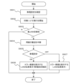
次に、印刷システム1000が実行する印刷処理時のエラー表示処理について、図8のフローチャートを参照して説明を行う。なお本処理は、CPUである制御部205が、ROM207に記憶されたプログラムをRAM208に読み出して実行することで実現される。
S801で、印刷装置100の制御部205は、印刷ジョブが投入されると受信印刷ジョブを解釈し、印刷の実行を開始する。
S802で、制御部205は受信したエラーコードによりから印刷実行中にシート処理装置200装置における紙ジャムの発生と発生位置を検知する。紙ジャムが発生したと判断した場合(S802でYes)の場合は、S803に処理を進め、紙ジャムが発生していない場合(S802でNoの場合)は、印刷ジョブの処理が最後まで滞りなく実行できたので、処理を終了する。
紙ジャムが発生した場合は、S803において、制御部205は、シートの搬送を中断する。
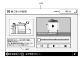
続くS804で、印刷装置100の制御部205は、印刷装置100の操作部204にジャムのエラー通知画面を表示させる。
図10は印刷システム1000のエラー通知画面1001である。S804にて、検知した紙ジャムの発生位置を印刷システム1000の側面図に表示している。さらに欄1002に、除電処理が原因で紙ジャムが発生している可能性があるため設定値の再確認をユーザに促すメッセージが表示されている。
その後、処理を終了する。
以上により、印刷システム1000において紙ジャムが発生した際に除電処理が適切な設定となっていない可能性を指摘し、適切な処置をユーザに促すことが可能となる。
Error Display Processing Next, the error display processing during printing processing executed by the
In step S801, when a print job is received, the
In S802, the
If a paper jam occurs, the
In the next step S804, the
10 shows an
Then, the process ends.
As a result, when a paper jam occurs in the
<第2の実施形態>
第1の実施形態のものは、紙ジャムの発生時に除電装置の影響を考慮したエラーメッセージを表示するものであった。しかし、除電装置の除電処理の設定値がOFFとなっている場合は除電処理を実施しないため、紙ジャムに対する影響はない。この場合を考慮し、第2の実施形態においては、除電装置が稼働しているか、すなわち除電処理の設定値のON/OFFによってエラーメッセージ表示を切り替える場合について説明する。
Second Embodiment
In the first embodiment, an error message is displayed taking into consideration the effect of the static eliminator when a paper jam occurs. However, if the static elimination setting of the static elimination device is set to OFF, the static elimination process is not performed, so there is no effect on the paper jam. Taking this case into consideration, in the second embodiment, a case will be described in which the error message display is switched depending on whether the static elimination device is operating, i.e., whether the static elimination setting is ON or OFF.
・エラー表示処理
図9に印刷システム1000が実行する印刷処理時のエラー表示処理のフローチャートを示す。本処理は、制御部205が、ROM207に記憶されたプログラムをRAM208に読み出して実行することで実現される。
S901で、印刷システム1000の制御部205は、起動時に除電装置200-3aの除電設定がONになっているかOFFになっているかを確認する。具体的には、印刷装置100の制御部205からの問い合わせを受けた除電装置200-3aの制御部501が、除電装置200-3aの操作部502のモード設定スイッチ601の状態を取得し、印刷装置100の制御部205に返信することで実現される。
続くS902で、制御部205は印刷ジョブの受信をトリガーとして、印刷処理の実行を開始する。
S903で、制御部205はエラーコード通知により紙ジャムが発生したことを検知したか否かを判断する。紙ジャムの発生を検知した場合(S903でYesの場合)は、S904に処理を進め、紙ジャムが発生していない場合(S903でNoの場合)は、印刷ジョブの処理が最後まで滞りなく実行できたので、処理を終了する。
S904で、制御部205は、シートの搬送を中断するよう制御する。
続くS905で、制御部205は除電設定の確認(S901)の結果がONであった場合(除電装置が稼働している場合)、処理をS906に進める。また、制御部205は除電設定の確認(S901)の結果がOFFであった場合(除電装置が稼働していない場合)は、処理をS907に進める。
S906で、制御部205は、ジャム位置に加えて除電設定の確認を促すエラーメッセージを操作部204に表示(図10)し、処理を終了する。
S907で、制御部205は操作部204にジャム位置のみを表示し、処理を終了する。
本実施形態によれば、除電設定を考慮したエラー表示を行うことが出来、よりユーザに適切な操作を促すことが可能となる。
9 shows a flowchart of an error display process during printing executed by the
In S901, the
In the next step S902, the
In S903, the
In S904, the
In the next step S905, if the result of checking the static elimination setting (S901) is ON (if the static eliminator is operating), the
In S906, the
In S907, the
According to this embodiment, an error display can be performed taking into consideration the static elimination settings, and it is possible to prompt the user to perform a more appropriate operation.
<第3の実施形態>
第2の実施形態において、除電設定のON/OFFを考慮したが、除電設定がONの場合であっても、除電装置200-3aより前の工程で紙ジャムが発生した場合は除電処理の影響はない。そのため、第3の実施形態においては、除電装置200-3aの接続位置と紙ジャムの発生位置の位置関係に応じてエラー表示を行う場合について説明する。
・エラー表示処理
図11は第1の実施形態において、除電装置200-3aの接続位置に応じてエラー表示を行う処理について説明する。図11のフローチャートは、制御部205が、ROM207に記憶されたプログラムをRAM208に読み出して実行することで実現される。
S1101で、印刷システム1000の制御部205は起動時に除電装置200-3aの接続位置を確認する。印刷ジョブ開始以降のS801-S803は第1の実施形態と同じ処理のため、説明は省略する。なお、S802で、エラーコードに基づき紙ジャムの発生位置を検知していることを活用する。
S1102で、紙ジャム発生後、制御部205は除電装置200-3aの接続位置と紙ジャム発生位置を比較する。制御部205は、紙ジャムの発生位置が除電装置200-3aより後の工程で発生している場合(S1102でYesの場合)、S1103に処理を進める。また、制御部205は紙ジャム発生位置が除電装置200-3aより前の工程で発生していると判断した場合(S1102でNoの場合)は、処理をS1104に進める。
S1103で、紙ジャムの発生位置に加えて除電設定の確認を促すエラーメッセージを操作部204に表示し、処理を終了する。
S1104で、制御部205は操作部204にジャム位置のみを表示し、処理を終了する。
本実施形態によれば、紙ジャムの発生位置と除電装置との位置関係から、紙ジャブの原因が除電処理と関係があるか否かを判断して、エラー表示を行うことが出来、よりユーザに適切な操作を促すことが可能となる。
Third Embodiment
In the second embodiment, the ON/OFF state of the static elimination setting was taken into consideration, but even if the static elimination setting is ON, if a paper jam occurs in a process prior to the static elimination device 200-3a, there is no effect of the static elimination process. Therefore, in the third embodiment, a case will be described in which an error is displayed according to the positional relationship between the connection position of the static elimination device 200-3a and the position where the paper jam occurred.
- Error display processing
Fig. 11 explains the process of displaying an error message according to the connection position of the static eliminator 200-3a in the first embodiment. The flowchart in Fig. 11 is implemented by the
In S1101, the
In S1102, after a paper jam occurs, the
In S1103, an error message prompting the user to check the static electricity removal settings in addition to displaying the location where the paper jam has occurred is displayed on the operation unit 204, and the process ends.
In S1104, the
According to this embodiment, based on the relative position of the location where the paper jam occurred and the position of the de-ionization device, it is possible to determine whether or not the cause of the paper jab is related to the de-ionization process, and an error message can be displayed, making it possible to prompt the user to perform more appropriate operations.
<第4の実施形態>
次に、除電装置200-3aの除電処理の設定ON/OFFと、除電装置200-3aの接続位置の両方を考慮したエラー表示について図12を用いて説明する。図12のフローチャートは、制御部205が、ROM207に記憶されたプログラムをRAM208に読み出して実行することで実現される。
Fourth Embodiment
Next, an error display that takes into consideration both the ON/OFF setting of the static elimination process of the static elimination device 200-3a and the connection position of the static elimination device 200-3a will be described with reference to Fig. 12. The flowchart in Fig. 12 is implemented by the
・エラー表示処理
S1201で、印刷システム1000の制御部205は起動時に除電装置200-3aが稼働しているか(除電設定がON/OFFか)を確認する。
S1202で、制御部205は、確認された除電設定がONかOFFかを判断する。除電設定がONになっている場合は、S1203に処理を進め、除電設定がOFFになっている場合は、S902に処理を進める。
S1203で、制御部205は除電装置200-3aの接続位置を確認する。印刷ジョブ開始以降のS902~S904は第2の実施形態(図9)と同じ処理のため、説明は省略する。
続くS1205で、制御部205は除電設定の確認(S1201)の結果がONであった場合(稼働している場合)、処理をS1206に進め、除電設定の確認(S1201)の結果がOFFであった場合(稼働していない場合)は、処理をS1208に進める。
S1206で、制御部205は先の除電設定の確認結果をもとに設定がONの場合は除電装置200-3aの接続位置とジャム発生位置の位置関係を確認する。紙ジャム発生位置が除電装置200-3aより後の工程で発生していると判断した場合(S1206でYesの場合)は、処理をS1207に進め、前の工程で発生していると判断した場合(S1206でNoの場合)は、処理をS1208に進める。
S1207で、ジャム位置に加えて除電設定の確認を促すエラーメッセージを操作部204に表示し、処理を終了する。
S1208で、制御部205は操作部204にジャム位置のみを表示し、処理を終了する。
これらによって、除電装置200-3aの接続位置と紙ジャムの位置関係、及び除電設定のON/OFFに応じた適切なエラー表示を行うことができる。
以上エラーメッセージを表示部に表示することとしたが、ユーザに通知する方法として、音声ガイド等他の通知手段でもよい。
In the error display process S1201, the
In S1202, the
In S1203, the
In the following S1205, if the result of checking the static elimination setting (S1201) is ON (if the device is operating), the
In S1206, the
In S1207, an error message prompting the user to check the static electricity removal settings in addition to the jam position is displayed on the operation unit 204, and the process ends.
In S1208, the
This makes it possible to display an appropriate error message according to the relationship between the connection position of the static elimination device 200-3a and the position of the paper jam, and the ON/OFF state of the static elimination setting.
Although an error message is displayed on the display unit as described above, other notification means such as a voice guide may be used to notify the user.
本実施形態の開示は、以下の構成、方法及びプログラムを含む。
(構成1)
シートへ印刷処理を実行する印刷装置と印刷されたシートの除電処理を行う除電装置とを備える印刷システムであって、
シートのジャムが発生した場合に、印刷処理を中断する制御手段と、
少なくとも前記ジャムの発生位置とユーザに除電設定の確認を促すメッセージを表示する表示手段とを有することを特徴とする印刷システム。
(構成2)
前記ジャムの発生位置を検知する検知手段を有し、
前記表示手段は、
前記検知手段により検知されたジャムの発生位置と前記除電装置の接続位置の位置関係に応じて除電設定の確認を促すメッセージを表示する
ことを特徴とする構成1に記載の印刷システム。
(構成3)
前記表示手段は、
前記ジャムの発生位置が、前記除電装置より前の位置で発生した場合は、除電設定の確認を促すメッセージを表示しない
ことを特徴とする構成1又は2のいずれか1つ記載の印刷システム。
(構成4)
前記表示手段は、
前記除電装置が稼働しているか否かを確認し、前記除電装置の稼働している場合は、除電設定の確認を促すメッセージを表示する
ことを特徴とする構成1~3のいずれか1つに記載の印刷システム。
(構成5)
シートの除電処理を行う除電装置にシートを搬送する印刷装置であって、
シートのジャムが発生した場合に、印刷処理を中断する制御手段と、
少なくとも前記ジャムの発生位置とユーザに除電設定の確認を促すメッセージを表示する表示手段とを有することを特徴とする印刷装置。
(構成6)
前記ジャムの発生位置を検知する検知手段を有し、
前記表示手段は、
前記検知手段により検知されたジャムの発生位置と前記除電装置の接続位置の位置関係に応じて除電設定の確認を促すメッセージを表示する
ことを特徴とする構成5に記載の印刷装置。
(構成7)
前記表示手段は、
前記ジャムの発生位置が、前記除電装置より前の位置で発生した場合は、除電設定の確認を促すメッセージを表示しない
ことを特徴とする構成5又は6記載の印刷装置。
(構成8)
前記表示手段は、
前記除電装置が稼働しているか否かを確認し、前記除電装置の稼働している場合は、除電設定の確認を促すメッセージを表示する
ことを特徴とする構成5~7のいずれか1つに記載の印刷装置。
(方法1)
シートへ印刷処理を実行する印刷装置と印刷されたシートの除電処理を行う除電装置とを備える印刷システムの制御方法であって、
シートのジャムが発生した場合に、印刷処理を中断し、前記ジャムの発生位置とユーザに除電設定の確認を促すメッセージを表示手段に表示する
を特徴とする印刷システムの制御方法。
(方法2)
シートの除電処理を行う除電装置にシートを搬送する印刷装置の制御方法であって、
シートのジャムが発生した場合に、印刷処理を中断する制御手段と、
前記ジャムの発生位置とユーザに除電設定の確認を促すメッセージを表示する表示手段とを有することを特徴とする印刷装置の制御方法。
(プログラム1)
方法1に記載の印刷システムの制御方法を、コンピュータに実行させるためのプログラム。
(プログラム2)
方法2に記載の印刷装置の制御方法を、コンピュータに実行させるためのプログラム。
The disclosure of this embodiment includes the following configuration, method, and program.
(Configuration 1)
A printing system including a printing device that executes a printing process on a sheet and a static elimination device that executes a static elimination process on the printed sheet,
A control means for interrupting a printing process when a sheet jam occurs;
A printing system comprising a display unit that displays at least the location where the jam has occurred and a message that prompts a user to check a static elimination setting.
(Configuration 2)
A detection means for detecting a position where the jam has occurred is provided,
The display means includes:
The printing system according to
(Configuration 3)
The display means includes:
3. The printing system according to
(Configuration 4)
The display means includes:
The printing system according to any one of
(Configuration 5)
A printing apparatus that conveys a sheet to a static elimination device that performs a static elimination process on the sheet,
A control means for interrupting a printing process when a sheet jam occurs;
A printing apparatus comprising: a display unit that displays at least the location of the jam and a message that prompts a user to check a static elimination setting.
(Configuration 6)
A detection means for detecting a position where the jam has occurred is provided,
The display means is
The printing apparatus according to
(Configuration 7)
The display means is
7. The printing apparatus according to
(Configuration 8)
The display means includes:
The printing device according to any one of
(Method 1)
A control method for a printing system including a printing device that executes a printing process on a sheet and a static elimination device that executes a static elimination process on the printed sheet, comprising:
A control method for a printing system, comprising the steps of: when a sheet jam occurs, interrupting a printing process; and displaying, on a display means, a position where the jam has occurred and a message urging a user to check a static elimination setting.
(Method 2)
A method for controlling a printing apparatus that conveys a sheet to a static elimination device that performs a static elimination process on the sheet, comprising:
A control means for interrupting a printing process when a sheet jam occurs;
The control method for a printing apparatus further comprises display means for displaying the location of the jam and a message for prompting a user to check a static elimination setting.
(Program 1)
A program for causing a computer to execute the printing system control method according to the first method.
(Program 2)
A program for causing a computer to execute the printing device control method described in
(その他の実施例)
本発明は、上述の実施形態の1以上の機能を実現するプログラムを、ネットワーク又は記憶媒体を介してシステム又は装置に供給し、そのシステム又は装置のコンピュータにおける1つ以上のプロセッサーがプログラムを読出し実行する処理でも実現可能である。また、1以上の機能を実現する回路(例えば、ASIC)によっても実現可能である。
(Other Examples)
The present invention can also be realized by a process in which a program for implementing one or more of the functions of the above-described embodiments is supplied to a system or device via a network or a storage medium, and one or more processors in a computer of the system or device read and execute the program. The present invention can also be realized by a circuit (e.g., ASIC) that implements one or more of the functions.
S801 印刷処理
S802 紙ジャム検知処理
S803 印刷ジョブ停止処理
S804 紙ジャムエラー表示処理
S801 Print process S802 Paper jam detection process S803 Print job stop process S804 Paper jam error display process
Claims (12)
シートのジャムが発生した場合に、印刷処理を中断する制御手段と、
少なくとも前記ジャムの発生位置とユーザに除電設定の確認を促すメッセージを表示する表示手段とを有することを特徴とする印刷システム。 A printing system including a printing device that executes a printing process on a sheet and a static elimination device that executes a static elimination process on the printed sheet,
A control means for interrupting a printing process when a sheet jam occurs;
A printing system comprising a display unit that displays at least the location where the jam has occurred and a message that prompts a user to check a static elimination setting.
前記表示手段は、
前記検知手段により検知されたジャムの発生位置と前記除電装置の接続位置の位置関係に応じて除電設定の確認を促すメッセージを表示する
ことを特徴とする請求項1に記載の印刷システム。 A detection means for detecting a position where the jam has occurred is provided,
The display means includes:
2. The printing system according to claim 1, further comprising: a display unit that displays a message prompting a user to confirm a static elimination setting in accordance with a positional relationship between a position where a jam has occurred and a connection position of the static elimination device, the position being determined by the detection unit.
前記ジャムの発生位置が、前記除電装置より前の位置で発生した場合は、除電設定の確認を促すメッセージを表示しない
ことを特徴とする請求項2記載の印刷システム。 The display means includes:
3. The printing system according to claim 2, wherein if the jam occurs at a position before the static elimination device, a message prompting the user to check static elimination settings is not displayed.
前記除電装置が稼働しているか否かを確認し、前記除電装置の稼働している場合は、除電設定の確認を促すメッセージを表示する
ことを特徴とする請求項1~3のいずれか1項に記載の印刷システム。 The display means includes:
A printing system according to any one of claims 1 to 3, characterized in that it checks whether the static elimination device is operating, and if the static elimination device is operating, displays a message prompting the user to check the static elimination settings.
シートのジャムが発生した場合に、印刷処理を中断する制御手段と、
少なくとも前記ジャムの発生位置とユーザに除電設定の確認を促すメッセージを表示する表示手段とを有することを特徴とする印刷装置。 A printing apparatus that conveys a sheet to a static elimination device that performs a static elimination process on the sheet,
A control means for interrupting a printing process when a sheet jam occurs;
A printing apparatus comprising: a display unit that displays at least the location of the jam and a message that prompts a user to check a static elimination setting.
前記表示手段は、
前記検知手段により検知されたジャムの発生位置と前記除電装置の接続位置の位置関係に応じて除電設定の確認を促すメッセージを表示する
ことを特徴とする請求項5に記載の印刷装置。 A detection means for detecting a position where the jam has occurred is provided,
The display means includes:
6. The printing apparatus according to claim 5, further comprising: a display unit that displays a message prompting a user to confirm a static elimination setting in accordance with a positional relationship between a position where a jam has occurred and a connection position of the static elimination device, the position being determined by the detection unit.
前記ジャムの発生位置が、前記除電装置より前の位置で発生した場合は、除電設定の確認を促すメッセージを表示しない
ことを特徴とする請求項6記載の印刷装置。 The display means includes:
7. The printing apparatus according to claim 6, wherein if the jam occurs at a position before the static elimination device, a message prompting the user to check static elimination settings is not displayed.
前記除電装置が稼働しているか否かを確認し、前記除電装置の稼働している場合は、除電設定の確認を促すメッセージを表示する
ことを特徴とする請求項5~7のいずれか1項に記載の印刷装置。 The display means includes:
The printing device according to any one of claims 5 to 7, characterized in that it checks whether the static elimination device is operating, and if the static elimination device is operating, displays a message prompting the user to check the static elimination settings.
シートのジャムが発生した場合に、印刷処理を中断し、前記ジャムの発生位置とユーザに除電設定の確認を促すメッセージを表示手段に表示する
を特徴とする印刷システムの制御方法。 A control method for a printing system including a printing device that executes a printing process on a sheet and a static elimination device that executes a static elimination process on the printed sheet, comprising:
A control method for a printing system, comprising the steps of: when a sheet jam occurs, interrupting a printing process; and displaying, on a display means, a position where the jam has occurred and a message urging a user to check a static elimination setting.
シートのジャムが発生した場合に、印刷処理を中断する制御手段と、
前記ジャムの発生位置とユーザに除電設定の確認を促すメッセージを表示する表示手段とを有することを特徴とする印刷装置の制御方法。 A method for controlling a printing apparatus that conveys a sheet to a static elimination device that performs a static elimination process on the sheet, comprising:
A control means for interrupting a printing process when a sheet jam occurs;
The control method for a printing apparatus further comprises display means for displaying the location of the jam and a message for prompting a user to check a static elimination setting.
Priority Applications (3)
| Application Number | Priority Date | Filing Date | Title |
|---|---|---|---|
| JP2023031383A JP2024123741A (en) | 2023-03-01 | 2023-03-01 | PRINTING SYSTEM, PRINTING APPARATUS, PRINTING SYSTEM CONTROL METHOD, PRINTING APPARATUS CONTROL METHOD, AND PROGRAM |
| US18/586,258 US20240294020A1 (en) | 2023-03-01 | 2024-02-23 | Print apparatus, method of controlling print apparatus, and storage medium |
| CN202410216631.0A CN118578792A (en) | 2023-03-01 | 2024-02-27 | Printing device and printing device control method |
Applications Claiming Priority (1)
| Application Number | Priority Date | Filing Date | Title |
|---|---|---|---|
| JP2023031383A JP2024123741A (en) | 2023-03-01 | 2023-03-01 | PRINTING SYSTEM, PRINTING APPARATUS, PRINTING SYSTEM CONTROL METHOD, PRINTING APPARATUS CONTROL METHOD, AND PROGRAM |
Publications (2)
| Publication Number | Publication Date |
|---|---|
| JP2024123741A true JP2024123741A (en) | 2024-09-12 |
| JP2024123741A5 JP2024123741A5 (en) | 2026-03-04 |
Family
ID=92526674
Family Applications (1)
| Application Number | Title | Priority Date | Filing Date |
|---|---|---|---|
| JP2023031383A Pending JP2024123741A (en) | 2023-03-01 | 2023-03-01 | PRINTING SYSTEM, PRINTING APPARATUS, PRINTING SYSTEM CONTROL METHOD, PRINTING APPARATUS CONTROL METHOD, AND PROGRAM |
Country Status (3)
| Country | Link |
|---|---|
| US (1) | US20240294020A1 (en) |
| JP (1) | JP2024123741A (en) |
| CN (1) | CN118578792A (en) |
Family Cites Families (4)
| Publication number | Priority date | Publication date | Assignee | Title |
|---|---|---|---|---|
| JP2009001418A (en) * | 2007-05-22 | 2009-01-08 | Komori Corp | Static eliminator for sheet-like material handling equipment |
| JP6682286B2 (en) * | 2016-02-04 | 2020-04-15 | キヤノン株式会社 | Image forming apparatus, control method thereof, and program |
| JP2017191288A (en) * | 2016-04-15 | 2017-10-19 | 京セラドキュメントソリューションズ株式会社 | Image forming apparatus |
| KR20240014145A (en) * | 2022-07-25 | 2024-02-01 | 휴렛-팩커드 디벨롭먼트 컴퍼니, 엘.피. | Determining cause of paper jam |
-
2023
- 2023-03-01 JP JP2023031383A patent/JP2024123741A/en active Pending
-
2024
- 2024-02-23 US US18/586,258 patent/US20240294020A1/en active Pending
- 2024-02-27 CN CN202410216631.0A patent/CN118578792A/en active Pending
Also Published As
| Publication number | Publication date |
|---|---|
| US20240294020A1 (en) | 2024-09-05 |
| CN118578792A (en) | 2024-09-03 |
Similar Documents
| Publication | Publication Date | Title |
|---|---|---|
| KR20140010891A (en) | Printing apparatus and method for controlling the same | |
| KR101313914B1 (en) | Image forming apparatus, method of controlling the same, and computer-readable storage medium | |
| US20110135326A1 (en) | Printing apparatus, method of controlling printing apparatus, and program | |
| US9377975B2 (en) | Printing apparatus, control method thereof, and storage medium | |
| US20250370394A1 (en) | Printing system, control method therefor, and storage medium | |
| US20250237980A1 (en) | Printing system, static elimination apparatus, method for controlling printing system, and storage medium | |
| JP2024123741A (en) | PRINTING SYSTEM, PRINTING APPARATUS, PRINTING SYSTEM CONTROL METHOD, PRINTING APPARATUS CONTROL METHOD, AND PROGRAM | |
| US12535759B2 (en) | Printing apparatus capable of controlling a static electricity elimination apparatus, control method for controlling printing apparatus, and storage medium | |
| US20240256812A1 (en) | Printing apparatus, control method thereof, and storage medium | |
| US20260010093A1 (en) | Printing system outputting a sheet on which charge removal processing is performed and control method therefor | |
| JP2025106860A (en) | Printing system, control method thereof, and program | |
| US12619188B2 (en) | Printing system, method of controlling the same, and storage medium | |
| JP2024157213A (en) | Printing system including static elimination device, and control method and program thereof | |
| JP2024123740A (en) | Printing system, control method thereof, and program | |
| JP2025127109A (en) | Printing system, control method thereof, and program | |
| US20260010109A1 (en) | Print system, method of controlling print system performing static electricity elimination processing, and storage medium | |
| JP2025127207A (en) | Printing system, control method thereof, and program | |
| JP2025073640A (en) | Printing system including static elimination device, and control method and program thereof | |
| US20250244710A1 (en) | Printing system, control method thereof, and storage medium | |
| JP2024124346A (en) | Printing system, control method thereof and program | |
| JP7764128B2 (en) | Image forming device | |
| US20240319649A1 (en) | Printing system, method for controlling the same, and storage medium | |
| JP2024137420A (en) | Printing system, control method thereof and program | |
| JP2025115420A (en) | Printing system including static eliminator, control method thereof, and program | |
| JP2025073534A (en) | Printing system including static elimination device, and control method and program thereof |
Legal Events
| Date | Code | Title | Description |
|---|---|---|---|
| A521 | Request for written amendment filed |
Free format text: JAPANESE INTERMEDIATE CODE: A523 Effective date: 20260224 |
|
| A621 | Written request for application examination |
Free format text: JAPANESE INTERMEDIATE CODE: A621 Effective date: 20260224 |