JP2025068942A - Positioning mechanism for tool holder - Google Patents

Positioning mechanism for tool holder Download PDF

Info

Publication number
JP2025068942A
JP2025068942A JP2023179076A JP2023179076A JP2025068942A JP 2025068942 A JP2025068942 A JP 2025068942A JP 2023179076 A JP2023179076 A JP 2023179076A JP 2023179076 A JP2023179076 A JP 2023179076A JP 2025068942 A JP2025068942 A JP 2025068942A
Authority
JP
Japan
Prior art keywords
tool holder
lever member
bolt
positioning
positioning mechanism
Prior art date
Legal status (The legal status is an assumption and is not a legal conclusion. Google has not performed a legal analysis and makes no representation as to the accuracy of the status listed.)
Pending
Application number
JP2023179076A
Other languages
Japanese (ja)
Inventor
慎也 成瀬
Shinya Naruse
Current Assignee (The listed assignees may be inaccurate. Google has not performed a legal analysis and makes no representation or warranty as to the accuracy of the list.)
Okuma Corp
Original Assignee
Okuma Corp
Okuma Machinery Works Ltd
Priority date (The priority date is an assumption and is not a legal conclusion. Google has not performed a legal analysis and makes no representation as to the accuracy of the date listed.)
Filing date
Publication date
Application filed by Okuma Corp, Okuma Machinery Works Ltd filed Critical Okuma Corp
Priority to JP2023179076A priority Critical patent/JP2025068942A/en
Publication of JP2025068942A publication Critical patent/JP2025068942A/en
Pending legal-status Critical Current

Links

Images

Landscapes

  • Cutting Tools, Boring Holders, And Turrets (AREA)

Abstract

To enable easy positioning of a tool holder in a space-saving manner without modification of a holder holding device and ensure sufficient adjustment allowance.SOLUTION: A positioning mechanism 15 includes: a reference block 16 provided on a tool holder 10; and a position adjustment part 17 that can adjust the position of the tool holder 10. The position adjustment part 17 includes: a bolt 20 provided on the tool holder 10; a lever member 19 that is provided in a tiltable manner with the lower end of a fulcrum piece 27 in contact with a mounting surface 2 as a fulcrum, and can press the bolt 20 by tilting; and an operation screw 22 that is movably provided with respect to the lever member 19 and can press the lever member 19 through a movement operation to the lever member 19. The operation screw 22 is movably provided in a direction orthogonal to the mounting surface 2. When the lever member 19 is pressed through the movement operation and tilted with the lower end of the fulcrum piece 27 as the fulcrum, the bolt 20 is pressed via the lever member 19 and the tool holder 10 is moved to a fixed position.SELECTED DRAWING: Figure 2

Description

本開示は、工具が取り付けられた工具ホルダをタレット等のホルダ保持装置に固定する際、工具ホルダをホルダ保持装置に位置決めするための位置決め機構に関する。 This disclosure relates to a positioning mechanism for positioning a tool holder on a holder holding device such as a turret when fixing a tool holder with a tool attached to the holder holding device.

例えば旋盤に設けた刃物台には、タレットの周面に複数の工具ホルダが固定されている。図15Aに示すように、工具ホルダ60は、タレット50の取付面51に固定されて、タレット50から突出する突出端部に工具61が取り付けられている。工具ホルダ60は、図示しない固定ボルトで取付面51に固定される。
工具ホルダ60の突出端部の底面には、タレット50への固定位置でタレット50の端面に当接する基準ブロック62が設けられている。工具ホルダ60の突出端部と反対側の端部には、工具ホルダ60を固定位置で位置決めする位置決め機構63が設けられている。この位置決め機構63は、工具ホルダ60の端面から下向きに突出してタレット50の反対側の端面に当接するテコ式ガイド64と、このテコ式ガイド64をタレット50の端面を押圧する方向へ傾動させる図示しない送りネジとを備えている。ここでは六角棒レンチ65等の工具で送りネジを回転操作してテコ式ガイド64を傾動させると、工具ホルダ60が矢印の方向に引っ張られて基準ブロック62がタレット50の端面に当接する固定位置に位置決めされる。位置決め後、工具ホルダ60に上方から貫通させた固定ボルトを取付面51の図示しないネジ孔にねじ込むと、工具ホルダ60が固定される。
For example, a tool rest provided on a lathe has a plurality of tool holders fixed to the peripheral surface of a turret. As shown in Fig. 15A, a tool holder 60 is fixed to a mounting surface 51 of a turret 50, and a tool 61 is attached to an end portion protruding from the turret 50. The tool holder 60 is fixed to the mounting surface 51 with a fixing bolt (not shown).
A reference block 62 is provided on the bottom surface of the protruding end of the tool holder 60, which abuts against the end surface of the turret 50 at a fixed position to the turret 50. A positioning mechanism 63 for positioning the tool holder 60 at a fixed position is provided on the end opposite to the protruding end of the tool holder 60. The positioning mechanism 63 includes a lever guide 64 that protrudes downward from the end surface of the tool holder 60 and abuts against the end surface opposite to the turret 50, and a feed screw (not shown) that tilts the lever guide 64 in a direction to press the end surface of the turret 50. Here, when the feed screw is rotated with a tool such as a hexagonal wrench 65 to tilt the lever guide 64, the tool holder 60 is pulled in the direction of the arrow, and the reference block 62 is positioned at a fixed position where it abuts against the end surface of the turret 50. After positioning, a fixing bolt that is inserted through the tool holder 60 from above is screwed into a screw hole (not shown) in the mounting surface 51, and the tool holder 60 is fixed.

図15Aの位置決め機構63の場合、テコ式ガイド64を操作する六角棒レンチ65を差し込むための空間が必要となる。よって、図15Bのようにテコ式ガイド64に近い位置にカバー52等の干渉物が存在すると、工具ホルダ60の位置決め及び取り外しが困難となる。
そこで、特許文献1には、ツールホルダ(工具ホルダ)の底面に設けたシャンクを、タレットの端面に設けたシャンク穴に差し込むと共に、ツールホルダの底面に、基準穴と、偏心軸部を有する偏心軸を設ける一方、タレットの端面に、基準穴に嵌合する位置決めピンと、偏心軸部が挿入される挿入穴とを設けた工具クランプ装置の発明が開示されている。ここでは偏心軸を回転させて偏心軸部を挿入穴の内周壁に押圧させることで、位置決めピンを相反方向で基準穴に押圧させ、突っ張り力を作用させて固定することができる。
15A requires a space for inserting the hexagonal wrench 65 that operates the lever guide 64. Therefore, if an interfering object such as the cover 52 is present near the lever guide 64 as in FIG. 15B, it becomes difficult to position and remove the tool holder 60.
Therefore, Patent Document 1 discloses an invention of a tool clamping device in which a shank provided on the bottom surface of a tool holder is inserted into a shank hole provided on an end surface of a turret, a reference hole and an eccentric shaft having an eccentric shaft portion are provided on the bottom surface of the tool holder, and a positioning pin that fits into the reference hole and an insertion hole into which the eccentric shaft portion is inserted are provided on the end surface of the turret. Here, by rotating the eccentric shaft to press the eccentric shaft portion against the inner peripheral wall of the insertion hole, the positioning pin is pressed against the reference hole in the opposite direction, and a tension force is applied to fix the tool.

実開平3-109734号公報Japanese Utility Model Application Publication No. 3-109734

しかし、特許文献1の工具クランプ装置は、タレットに位置決めピンと挿入穴とを設ける必要があり、余計な加工が必要となる。
また、偏心軸部の回転をツールホルダの直線移動に変換するため、位置決めの調整代が少なくなっている。よって、この装置を回転工具ホルダに採用すると、工具を回転させる歯車の噛み合い位置が適正でない場合が生じても、調整代で噛み合い位置を修正できない状態が起こり得る。この場合、そのまま加工に使用すると騒音の原因となるおそれがある。
However, the tool clamping device of Patent Document 1 requires the provision of a positioning pin and an insertion hole in the turret, which requires extra machining.
In addition, because the rotation of the eccentric shaft is converted into linear movement of the tool holder, there is little adjustment margin for positioning. Therefore, if this device is used in a rotary tool holder, even if the meshing position of the gear that rotates the tool is not appropriate, it may not be possible to correct the meshing position with the adjustment margin. In this case, if it is used in machining as it is, it may cause noise.

そこで、本開示は、タレット等のホルダ保持装置に手を加えることなく、省スペースで容易に工具ホルダの位置決めが可能となり、十分な調整代も確保できる工具ホルダの位置決め機構を提供することを目的としたものである。 The present disclosure therefore aims to provide a tool holder positioning mechanism that allows for easy positioning of tool holders in a space-saving manner without modifying holder holding devices such as turrets, and that also ensures sufficient adjustment margins.

上記目的を達成するために、本開示は、工具を保持する工具ホルダを、ホルダ保持装置の取付面における所定の固定位置へ位置決めするための位置決め機構であって、
前記工具ホルダに設けられ、前記固定位置で前記ホルダ保持装置に当接可能な基準ブロックと、前記取付面に対する前記工具ホルダの位置を調整可能な位置調整部と、を有し、
前記位置調整部は、前記工具ホルダに設けられた被押圧部と、前記取付面と当接してその当接部位を支点として傾動可能に設けられ、当該傾動により前記被押圧部を押圧可能なテコ部材と、前記テコ部材に対して移動可能に設けられ、前記テコ部材への移動操作により前記テコ部材を押圧可能な操作部材と、を含み、
前記操作部材は、前記取付面との交差方向へ移動可能に設けられ、移動操作により前記テコ部材を押圧して前記取付面との当接部位を支点として傾動させることで、前記テコ部材を介して前記被押圧部を押圧し、前記工具ホルダを前記固定位置へ移動させることを特徴とする。
本開示の別の態様は、上記構成において、前記位置調整部は、前記テコ部材を前記被押圧部と直接又は間接的に当接させた状態で保持する弾性部材をさらに有することを特徴とする。
本開示の別の態様は、上記構成において、前記工具ホルダは、前記位置調整部を収容する収容部を有し、
前記位置調整部は、前記テコ部材を前記交差方向に付勢して前記テコ部材を前記収容部の内面に当接させる付勢手段をさらに有し、前記操作部材の移動操作により前記テコ部材を押圧することで、前記テコ部材は、前記取付面との当接部位を支点として変形を伴いながら傾動することを特徴とする。
本開示の別の態様は、上記構成において、前記テコ部材は、前記工具ホルダが前記固定位置に達した際に前記ホルダ保持装置に当接するストッパを有し、前記基準ブロックと前記ストッパとで前記ホルダ保持装置を挟持して前記工具ホルダを前記固定位置に位置決めすることを特徴とする。
本開示の別の態様は、上記構成において、前記被押圧部は、前記交差方向で前記テコ部材を貫通して前記工具ホルダにねじ込み結合されるボルトであり、前記テコ部材は、前記操作部材の押圧による傾動の際には、前記ボルトの貫通孔が前記ボルトを押圧して前記工具ホルダを移動させることを特徴とする。
In order to achieve the above object, the present disclosure provides a positioning mechanism for positioning a tool holder that holds a tool at a predetermined fixed position on a mounting surface of a holder holding device, the positioning mechanism comprising:
a reference block provided on the tool holder and capable of contacting the holder holding device at the fixed position; and a position adjustment unit capable of adjusting a position of the tool holder with respect to the mounting surface,
the position adjustment unit includes: a pressed portion provided on the tool holder; a lever member that is in contact with the mounting surface and tiltable about a contact point thereof and capable of pressing the pressed portion by the tilting; and an operating member that is movable relative to the lever member and capable of pressing the lever member by operating the lever member to move,
The operating member is provided so as to be movable in a direction intersecting the mounting surface, and by operating the operating member to press the lever member and tilt it about the contact point with the mounting surface as a fulcrum, the pressed portion is pressed via the lever member, and the tool holder is moved to the fixed position.
Another aspect of the present disclosure is characterized in that, in the above configuration, the position adjustment portion further has an elastic member that holds the lever member in direct or indirect contact with the pressed portion.
In another aspect of the present disclosure, in the above configuration, the tool holder has an accommodating portion that accommodates the position adjustment portion,
The position adjustment portion further has a biasing means for biasing the lever member in the intersecting direction to bring the lever member into contact with the inner surface of the accommodating portion, and is characterized in that by pressing the lever member by moving the operating member, the lever member tilts while deforming, with the contact point with the mounting surface as a fulcrum.
Another aspect of the present disclosure is characterized in that, in the above-mentioned configuration, the lever member has a stopper that abuts against the holder holding device when the tool holder reaches the fixed position, and the holder holding device is sandwiched between the reference block and the stopper to position the tool holder at the fixed position.
Another aspect of the present disclosure is characterized in that, in the above-mentioned configuration, the pressed portion is a bolt that passes through the lever member in the intersecting direction and is screwed into the tool holder, and when the lever member is tilted by being pressed by the operating member, a through hole of the bolt presses the bolt to move the tool holder.

本開示によれば、テコ部材を押圧する操作部材が取付面との交差方向へ移動操作されるので、工具ホルダの位置決め機構側にカバー等の干渉物があっても支障なく位置決め操作が可能となる。また、ホルダ保持装置に位置決めのための構成部を設けることなく、工具ホルダにテコ部材を含む位置調整部を設けるだけで位置決めが行えると共に、傾動するテコ部材によって工具ホルダの移動が効率よく行える。よって、ホルダ保持装置に手を加えることなく、省スペースで容易に工具ホルダの位置決めが可能となり、十分な調整代も確保できる。 According to the present disclosure, the operating member that presses the lever member is moved in a direction intersecting with the mounting surface, so that positioning can be performed without any problems even if there is an interfering object such as a cover on the tool holder positioning mechanism side. Furthermore, positioning can be performed simply by providing the tool holder with a position adjustment unit including a lever member without providing a positioning component on the holder holding device, and the tool holder can be moved efficiently by the tilting lever member. Therefore, the tool holder can be easily positioned in a space-saving manner without modifying the holder holding device, and sufficient adjustment margin can be ensured.

形態1の位置決め機構を備えた工具ホルダの説明図で、図1Aが平面、図1Bが背面をそれぞれ示す。1A and 1B are explanatory views of a tool holder equipped with a positioning mechanism of the first embodiment, in which FIG. 1A shows a plan view and FIG. 1B shows a rear view. 図1BのA-A線拡大断面図である。1C is an enlarged cross-sectional view of line AA in FIG. 1B. 形態1の位置決め機構部分の拡大図で、図3Aは位置決め前、図3Bは位置決め状態をそれぞれ示す。3A and 3B are enlarged views of the positioning mechanism portion of the first embodiment, in which FIG. 3A shows the mechanism before positioning and FIG. 3B shows the mechanism in a positioned state. 形態2の位置決め機構部分の拡大図で、図4Aは位置決め前、図4Bは位置決め状態をそれぞれ示す。4A and 4B are enlarged views of the positioning mechanism portion of the second embodiment, in which FIG. 4A shows the positioning mechanism portion before positioning and FIG. 4B shows the positioning mechanism portion after positioning. 形態3の位置決め機構部分の拡大図で、図5Aは位置決め前、図5Bは位置決め状態をそれぞれ示す。5A and 5B are enlarged views of the positioning mechanism portion of the third embodiment, in which FIG. 5A shows the positioning mechanism portion before positioning and FIG. 5B shows the positioning mechanism portion after positioning. 形態4の位置決め機構部分の拡大図で、図6Aは位置決め前、図6Bは位置決め状態をそれぞれ示す。6A and 6B are enlarged views of the positioning mechanism portion of the fourth embodiment, in which FIG. 6A shows the positioning mechanism portion before positioning and FIG. 6B shows the positioning mechanism portion after positioning. 形態5の位置決め機構部分の拡大図で、図7Aは位置決め前、図7Bは位置決め状態をそれぞれ示す。7A and 7B are enlarged views of the positioning mechanism portion of the fifth embodiment, in which FIG. 7A shows the positioning mechanism portion before positioning and FIG. 7B shows the positioning mechanism portion after positioning. 形態6の位置決め機構部分の拡大図で、図8Aは位置決め前、図8Bは位置決め状態をそれぞれ示す。8A and 8B are enlarged views of the positioning mechanism portion of the sixth embodiment, in which FIG. 8A shows the positioning mechanism portion before positioning and FIG. 8B shows the positioning mechanism portion after positioning. 形態7の位置決め機構部分の拡大図で、図9Aは位置決め前、図9Bは位置決め状態をそれぞれ示す。9A and 9B are enlarged views of the positioning mechanism portion of the seventh embodiment, in which FIG. 9A shows the positioning mechanism portion before positioning and FIG. 9B shows the positioning mechanism portion after positioning. 形態8の位置決め機構部分の拡大図で、図10Aは位置決め前、図10Bは位置決め状態をそれぞれ示す。10A and 10B are enlarged views of the positioning mechanism portion of the eighth embodiment, in which FIG. 10A shows the positioning mechanism before positioning and FIG. 10B shows the positioning mechanism after positioning. 図10AのB-B線断面図である。This is a cross-sectional view of line BB in Figure 10A. 形態8の位置調整部の説明図で、図12Aが平面、図12Bが側面、図12Cが背面をそれぞれ示す。12A is a plan view of the position adjustment part of the eighth embodiment, FIG. 12B is a side view, and FIG. 12C is a rear view. 形態8の位置調整部の斜視図である。FIG. 13 is a perspective view of the position adjustment part of embodiment 8. 形態8の位置調整部の分解斜視図である。FIG. 13 is an exploded perspective view of the position adjustment part of embodiment 8. 従来の位置決め機構の説明図で、図15Aが干渉物がない場合、図15Bが干渉物がある場合をそれぞれ示す。15A is an explanatory diagram of a conventional positioning mechanism when there is no interfering object, and FIG. 15B is a diagram showing the case when there is an interfering object.

以下、本開示の実施の形態を図面に基づいて説明する。
[形態1]
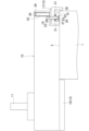
図1は、旋盤のタレットに固定される工具ホルダに本開示の位置決め機構を適用した一例を示す説明図である。図1Aが平面、図1Bが背面をそれぞれ示している。図2は、図1BのA-A線拡大断面図である。ここでは説明の便宜上、工具ホルダ10が突出する図1A及び図2の左側を前方、右側を後方として説明する。図1Bでは上側が上方となる。
タレット1の周面には、工具ホルダ10の取付面2が形成されている。取付面2には、工具ホルダ10を固定するための4本の固定ボルト4,4・・がねじ込まれる4つのネジ孔3,3・・が形成されている。タレット1は、本開示のホルダ保持装置の一例である。
工具ホルダ10は、タレット1の中心軸方向と平行となる前後方向に延びるブロック状で、工具11が取り付けられる前端がタレット1から前方へ突出した状態で固定される。
Hereinafter, an embodiment of the present disclosure will be described with reference to the drawings.
[Form 1]
Fig. 1 is an explanatory diagram showing an example in which the positioning mechanism of the present disclosure is applied to a tool holder fixed to the turret of a lathe. Fig. 1A shows a plan view, and Fig. 1B shows a rear view. Fig. 2 is an enlarged cross-sectional view taken along line A-A in Fig. 1B. For ease of explanation, the left side of Fig. 1A and Fig. 2, from which the tool holder 10 protrudes, will be described as the front, and the right side as the rear. In Fig. 1B, the upper side is the upper side.
A mounting surface 2 for a tool holder 10 is formed on the peripheral surface of the turret 1. The mounting surface 2 is formed with four screw holes 3, 3... into which four fixing bolts 4, 4... for fixing the tool holder 10 are screwed. The turret 1 is an example of a holder holding device of the present disclosure.
The tool holder 10 is in the form of a block extending in the front-rear direction parallel to the central axis of the turret 1, and is fixed with its front end, to which a tool 11 is attached, protruding forward from the turret 1.

工具ホルダ10には、取付面2の固定位置に位置決めするための位置決め機構15が設けられている。位置決め機構15は、基準ブロック16と、位置調整部17とを備えている。
基準ブロック16は、工具ホルダ10の前部底面へ一体に設けられて、下方へ突出する平面視矩形状となっている。基準ブロック16は、図15と同様に、工具ホルダ10の取付面2への固定位置で後面がタレット1の前面に当接する。
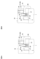
位置調整部17は、図3Aにも示すように、ベース部材18と、テコ部材19と、ボルト20と、4つのコイルバネ21,21・・と、操作ネジ22とを有している。工具ホルダ10の後部下側には、下面及び後面に開口して操作ネジ22を除く位置調整部17を収容する収容部23が切り欠き形成されている。
ベース部材18は、左右方向に延びる横長四角形の板体で、左右方向の中央には、下貫通孔24が形成されている。下貫通孔24の下部は、ボルト20の頭部25が収まるように上部よりも大径となっている。
The tool holder 10 is provided with a positioning mechanism 15 for positioning the tool holder 10 at a fixed position on the attachment surface 2. The positioning mechanism 15 includes a reference block 16 and a position adjustment portion 17.
The reference block 16 is integrally provided on the front bottom surface of the tool holder 10 and has a rectangular shape in a plan view that protrudes downward. As in the case of FIG. 15 , the rear surface of the reference block 16 abuts against the front surface of the turret 1 when the reference block 16 is fixed to the mounting surface 2 of the tool holder 10.
3A, the position adjustment part 17 has a base member 18, a lever member 19, a bolt 20, four coil springs 21, 21, ..., and an operating screw 22. A storage part 23 is cut out on the lower rear side of the tool holder 10, and opens to the bottom and rear faces to store the position adjustment part 17 excluding the operating screw 22.
The base member 18 is a horizontally elongated rectangular plate extending in the left-right direction, and has a lower through hole 24 formed in the left-right center. The lower part of the lower through hole 24 has a larger diameter than the upper part so that the head 25 of the bolt 20 can be accommodated therein.

テコ部材19は、ベース部材18と同様に左右方向へ延びる横長四角形の板状であるが、前後方向の長さはベース部材18よりも大きく形成されて、後端を収容部23から後方へ突出させている。テコ部材19の左右方向の中央には、上貫通孔26が形成されている。テコ部材19の前端には、下方へ直角に折曲されて下端が取付面2に当接する支点片27が形成されている。支点片27の下端は、本開示の取付面との当接部位の一例である。
テコ部材19の後端には、下方へ直角に折曲されてタレット1の後方まで延びた後、下端が前方へ直角に突出するストッパ片28が形成されている。ストッパ片28は、本開示のストッパの一例である。
The lever member 19 is a horizontally elongated rectangular plate extending in the left-right direction like the base member 18, but its length in the front-rear direction is greater than that of the base member 18, with its rear end protruding rearward from the housing portion 23. An upper through-hole 26 is formed in the center of the lever member 19 in the left-right direction. A fulcrum piece 27 is formed at the front end of the lever member 19, which is bent downward at a right angle and has its lower end abutting against the mounting surface 2. The lower end of the fulcrum piece 27 is an example of a portion abutting the mounting surface of the present disclosure.
A stopper piece 28 is formed at the rear end of the lever member 19, which is bent downward at a right angle, extends to the rear of the turret 1, and has a lower end that protrudes forward at a right angle. The stopper piece 28 is an example of a stopper of the present disclosure.

ボルト20は、ベース部材18の下貫通孔24とテコ部材19の上貫通孔26とをそれぞれ下方から貫通して、収容部23の上面にねじ込み結合されている。ボルト20は、頭部25が下貫通孔24の下部に収まって収容部23から下方へ突出しない位置までねじ込まれている。下貫通孔24と上貫通孔26とは、共にボルト20よりも大径であるが、上貫通孔26は、下貫通孔24の上部よりも大径に形成されている。ボルト20は、本開示の被押圧部の一例である。
コイルバネ21,21・・は、ベース部材18とテコ部材19との間でボルト20の左右に2つずつ配置されている。左右2つのコイルバネ21,21は、側面視でボルト20の前後に位置している。ベース部材18は、自重により下貫通孔24の下部上面にボルト20の頭部25が当接する下限位置にあり、テコ部材19は、各コイルバネ21により、ベース部材18から上方へ離間する位置で支持される。但し、テコ部材19は収容部23の上面に当接しない。
The bolt 20 penetrates the lower through hole 24 of the base member 18 and the upper through hole 26 of the lever member 19 from below, and is screwed and coupled to the upper surface of the housing portion 23. The bolt 20 is screwed into a position where the head 25 fits into the lower part of the lower through hole 24 and does not protrude downward from the housing portion 23. The lower through hole 24 and the upper through hole 26 are both larger in diameter than the bolt 20, but the upper through hole 26 is formed with a larger diameter than the upper part of the lower through hole 24. The bolt 20 is an example of a pressed portion of the present disclosure.
The coil springs 21, 21... are arranged two on each side of the bolt 20 between the base member 18 and the lever member 19. The two left and right coil springs 21, 21 are located in front of and behind the bolt 20 in a side view. The base member 18 is in a lowermost position where the head 25 of the bolt 20 abuts against the lower upper surface of the lower through-hole 24 due to its own weight, and the lever member 19 is supported by each coil spring 21 at a position spaced upward from the base member 18. However, the lever member 19 does not abut against the upper surface of the accommodation portion 23.

操作ネジ22は、収容部23の上側で工具ホルダ10へ上下方向に貫通形成されて下部が雌ネジとなる調整孔29に螺合している。調整孔29は、ボルト20よりも後方で工具ホルダ10の左右方向の中央に形成されている。操作ネジ22は、六角穴30を備えた上端が工具ホルダ10の上面と一致するねじ込み位置で、下端を収容部23の下面に一致させている。操作ネジ22は、回転操作により、取付面2と直交する上下方向に移動可能である。操作ネジ22は、本開示の操作部材の一例である。上下方向は、本開示の取付面との交差方向の一例である。 The operating screw 22 is screwed into an adjustment hole 29 that is formed above the storage section 23 and penetrates the tool holder 10 in the vertical direction, with the lower part being a female thread. The adjustment hole 29 is formed in the center of the tool holder 10 in the horizontal direction, behind the bolt 20. The operating screw 22 has a lower end that is aligned with the lower surface of the storage section 23 at a screw-in position where the upper end with the hexagonal hole 30 is aligned with the upper surface of the tool holder 10. The operating screw 22 can be moved in the vertical direction perpendicular to the mounting surface 2 by a rotation operation. The operating screw 22 is an example of an operating member of the present disclosure. The vertical direction is an example of a direction intersecting the mounting surface of the present disclosure.

以上の如く構成された位置決め機構15において、工具ホルダ10を位置決めする際、図2及び図3Aに示すように、工具ホルダ10の後部を取付面2に載置して、基準ブロック16をタレット1の前面に近接或いは当接する位置にセットする。この状態でテコ部材19のストッパ片28は、工具ホルダ10の下面を越えて下方へ延び、その下端をタレット1の後面に近接させている。
この状態で操作ネジ22の六角穴30に六角棒レンチを上方から嵌合させてねじ込み方向へ回転させると、図3Bに示すように、操作ネジ22が収容部23内に突出してボルト20の後方でテコ部材19に当接する。調整孔29に螺合した操作ネジ22のねじ込みを続けると、テコ部材19は、支点片27の下面後側の角を支点として図3Bにおける右回転方向へ傾動する。よって、上貫通孔26の上側の開口の前端がボルト20に当接してボルト20を後方へ押圧し、そのまま工具ホルダ10を矢印で示すように後方へスライドさせる。基準ブロック16がタレット1の前面に押圧されてテコ部材19のストッパ片28の下端がタレット1の後面に当接すると、テコ部材19の傾動が停止し、工具ホルダ10の位置決めが完了する。よって、この位置で各固定ボルト4をネジ孔3にそれぞれねじ込めば、工具ホルダ10の固定が完了する。
In positioning the tool holder 10 in the positioning mechanism 15 configured as above, as shown in Figures 2 and 3A, the rear part of the tool holder 10 is placed on the mounting surface 2 and the reference block 16 is set at a position close to or in contact with the front surface of the turret 1. In this state, the stopper piece 28 of the lever member 19 extends downward beyond the bottom surface of the tool holder 10 and has its lower end close to the rear surface of the turret 1.
In this state, when a hexagonal wrench is fitted into the hexagonal hole 30 of the operating screw 22 from above and rotated in the screwing direction, the operating screw 22 protrudes into the housing portion 23 and abuts against the lever member 19 behind the bolt 20, as shown in Fig. 3B. When the operating screw 22 screwed into the adjustment hole 29 continues to be screwed, the lever member 19 tilts in the right direction in Fig. 3B with the rear corner of the lower surface of the fulcrum piece 27 as a fulcrum. Therefore, the front end of the upper opening of the upper through hole 26 abuts against the bolt 20 and presses the bolt 20 backward, causing the tool holder 10 to slide backward as shown by the arrow. When the reference block 16 is pressed against the front surface of the turret 1 and the lower end of the stopper piece 28 of the lever member 19 abuts against the rear surface of the turret 1, the tilting of the lever member 19 stops and the positioning of the tool holder 10 is completed. Therefore, by screwing each of the fixing bolts 4 into the screw holes 3 at this position, the fixing of the tool holder 10 is completed.

このように、上記形態1の位置決め機構15は、工具ホルダ10に設けられ、固定位置でタレット1に当接可能な基準ブロック16と、取付面2に対する工具ホルダ10の位置を調整可能な位置調整部17とを有する。
位置調整部17は、工具ホルダ10に設けられたボルト20と、取付面2と当接する支点片27の下端を支点として傾動可能に設けられ、当該傾動によりボルト20を押圧可能なテコ部材19と、テコ部材19に対して移動可能に設けられ、テコ部材19への移動操作によりテコ部材19を押圧可能な操作ネジ22と、を含む。
そして、操作ネジ22は、取付面2との直交方向へ移動可能に設けられ、移動操作によりテコ部材19を押圧して支点片27の下端を支点として傾動させることで、テコ部材19を介してボルト20を押圧し、工具ホルダ10を固定位置へ移動させる。
Thus, the positioning mechanism 15 of the above-mentioned form 1 has a reference block 16 that is provided on the tool holder 10 and can abut against the turret 1 at a fixed position, and a position adjustment portion 17 that can adjust the position of the tool holder 10 relative to the mounting surface 2.
The position adjustment portion 17 includes a bolt 20 provided on the tool holder 10, a lever member 19 that is tiltable around the lower end of a fulcrum piece 27 that abuts the mounting surface 2 as a fulcrum and can press the bolt 20 by said tilting, and an operating screw 22 that is movable relative to the lever member 19 and can press the lever member 19 by moving the lever member 19.
The operating screw 22 is arranged to be movable in a direction perpendicular to the mounting surface 2, and by operating the operating screw 22 to press the lever member 19 and tilt it around the lower end of the fulcrum piece 27 as a fulcrum, the bolt 20 is pressed via the lever member 19, and the tool holder 10 is moved to a fixed position.

この構成によれば、テコ部材19を押圧する操作ネジ22が取付面2との直交方向へ移動操作されるので、工具ホルダ10の後方にカバー等の干渉物があっても、工具ホルダ10の上方から支障なく位置決め操作が可能となる。また、タレット1に位置決めのための構成部を設けることなく、工具ホルダ10にテコ部材19を含む位置調整部17を設けるだけで位置決めが行えると共に、傾動するテコ部材19によって工具ホルダ10の移動が効率よく行える。よって、タレット1に手を加えることなく、省スペースで容易に工具ホルダ10の位置決めが可能となり、十分な調整代も確保できる。
特に、テコ部材19は、工具ホルダ10が固定位置に達した際にタレット1に当接するストッパ片28を有し、基準ブロック16とストッパ片28とでタレット1を挟持して工具ホルダ10を固定位置に位置決めするので、正確な位置決めが迅速に行えると共に、操作ネジ22の過度なねじ込み操作が防止可能となる。
また、被押圧部を、上下方向でテコ部材19を貫通して工具ホルダ10にねじ込み結合されるボルト20として、テコ部材19は、操作ネジ22の押圧による傾動の際、ボルト20の上貫通孔26がボルト20を押圧して工具ホルダ10を移動させるようにしているので、ボルト20を利用したテコ部材19の支持と工具ホルダ10の移動とが容易に行える。
According to this configuration, the operating screw 22 that presses the lever member 19 is moved in a direction perpendicular to the mounting surface 2, so that even if there is an obstruction such as a cover behind the tool holder 10, positioning can be performed from above the tool holder 10 without hindrance. Furthermore, positioning can be performed simply by providing the tool holder 10 with a position adjustment unit 17 including the lever member 19 without providing a component for positioning on the turret 1, and the tool holder 10 can be moved efficiently by the tilting lever member 19. Therefore, the tool holder 10 can be positioned easily and in a small space without modifying the turret 1, and sufficient adjustment allowance can be ensured.
In particular, the lever member 19 has a stopper piece 28 that abuts against the turret 1 when the tool holder 10 reaches the fixed position, and the turret 1 is clamped between the reference block 16 and the stopper piece 28 to position the tool holder 10 at the fixed position. This allows for quick and accurate positioning and prevents the operating screw 22 from being screwed in excessively.
In addition, the pressed portion is the bolt 20 which passes through the lever member 19 in the vertical direction and is screwed into the tool holder 10. When the lever member 19 is tilted by pressing the operating screw 22, the upper through hole 26 of the bolt 20 presses the bolt 20 to move the tool holder 10. Therefore, the lever member 19 can be easily supported and the tool holder 10 can be easily moved by using the bolt 20.

以下、本開示の変更例を説明する。但し、形態1と同じ構成部には同じ符号を付して重複する説明を省略し、位置調整部17を中心に説明する。
[形態2]
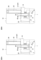
図4Aに示す位置決め機構15Aでは、テコ部材19に、先端にボール36を備えたスプリングプランジャ35が設けられている点が形態1と異なっている。テコ部材19の左右方向の中央には、ストッパ片28の後方から前後方向に貫通して前部が雌ネジとなる貫通孔37が形成されている。スプリングプランジャ35は、貫通孔37に後方から挿入されて雌ネジに螺合し、先端のボール36を上貫通孔26内に突出させている。ボール36は、図示しないバネによって前方へ突出付勢されて、ボルト20を上貫通孔26の前側内面に押圧している。よって、位置決め前のテコ部材19は、スプリングプランジャ35により後方へ付勢されて、上貫通孔26の前側内面にボルト20が当接する図4Aの位置に保持される。スプリングプランジャ35は、本開示の弾性部材の一例である。
Hereinafter, modified examples of the present disclosure will be described, in which the same components as those in the first embodiment are denoted by the same reference numerals and will not be described again. The position adjustment unit 17 will be mainly described.
[Form 2]
The positioning mechanism 15A shown in FIG. 4A is different from the first embodiment in that the lever member 19 is provided with a spring plunger 35 having a ball 36 at its tip. A through hole 37 is formed in the center of the lever member 19 in the left-right direction, penetrating the stopper piece 28 from the rear in the front-rear direction and having a female thread at its front part. The spring plunger 35 is inserted into the through hole 37 from the rear and screwed into the female thread, causing the ball 36 at its tip to protrude into the upper through hole 26. The ball 36 is biased forward by a spring (not shown) to protrude forward and press the bolt 20 against the front inner surface of the upper through hole 26. Therefore, the lever member 19 before positioning is biased backward by the spring plunger 35 and is held in the position of FIG. 4A where the bolt 20 abuts against the front inner surface of the upper through hole 26. The spring plunger 35 is an example of an elastic member of the present disclosure.

以上の如く構成された位置決め機構15Aにおいて、工具ホルダ10を位置決めする際、図4Aに示すように、工具ホルダ10の後部を取付面2に載置して、基準ブロック16をタレット1の前面に近接或いは当接する位置にセットする。
この状態で操作ネジ22をねじ込み方向へ回転させると、図4Bに示すように、操作ネジ22が収容部23内に突出してボルト20の後方でテコ部材19に当接する。調整孔29への操作ネジ22のねじ込みを続けると、テコ部材19は、支点片27の下面後側の角を支点として右回転方向へ傾き、同様に傾いた上貫通孔26の上側の開口の前端がボルト20を後方へ押圧し、そのまま工具ホルダ10を矢印で示すように後方へスライドさせる。このように、テコ部材19が傾くにつれてスプリングプランジャ35のボール36は没入方向へ押し込まれ、その反発力でボルト20と上貫通孔26の上端との当接状態を維持する。
基準ブロック16がタレット1の前面に押圧されてテコ部材19のストッパ片28の下端がタレット1の後面に当接すると、テコ部材19の傾動が停止し、工具ホルダ10の位置決めが完了する。よって、この位置で各固定ボルト4をネジ孔3にそれぞれねじ込めば、工具ホルダ10の固定が完了する。
In the positioning mechanism 15A configured as described above, when positioning the tool holder 10, as shown in FIG. 4A, the rear portion of the tool holder 10 is placed on the mounting surface 2, and the reference block 16 is set at a position close to or in contact with the front surface of the turret 1.
When the operating screw 22 is rotated in the screwing direction in this state, as shown in Fig. 4B, the operating screw 22 protrudes into the housing portion 23 and abuts against the lever member 19 behind the bolt 20. When the operating screw 22 continues to be screwed into the adjustment hole 29, the lever member 19 tilts in the clockwise direction with the rear corner of the lower surface of the fulcrum piece 27 as a fulcrum, and the front end of the upper opening of the upper through-hole 26, which is also tilted in a similar manner, presses the bolt 20 backward, causing the tool holder 10 to slide backward as shown by the arrow. In this manner, as the lever member 19 tilts, the ball 36 of the spring plunger 35 is pushed in the retracting direction, and the repulsive force of this pushes the bolt 20 and the upper end of the upper through-hole 26 together to maintain their abutment state.
When the reference block 16 is pressed against the front surface of the turret 1 and the lower end of the stopper piece 28 of the lever member 19 abuts against the rear surface of the turret 1, the tilting of the lever member 19 stops and the positioning of the tool holder 10 is completed. Therefore, if the fixing bolts 4 are screwed into the screw holes 3 at this position, the fixing of the tool holder 10 is completed.

このように、上記形態2の位置決め機構15Aにおいても、工具ホルダ10の後方にカバー等の干渉物があっても、工具ホルダ10の上方から支障なく位置決め操作が可能となる。また、タレット1に位置決めのための構成部を設けることなく、工具ホルダ10にテコ部材19を含む位置調整部17を設けるだけで位置決めが行えると共に、傾動するテコ部材19によって工具ホルダ10の移動が効率よく行える。よって、タレット1に手を加えることなく、省スペースで容易に工具ホルダ10の位置決めが可能となり、十分な調整代も確保できる。
特に形態2では、位置調整部17は、テコ部材19をボルト20と直接当接させた状態で保持するスプリングプランジャ35を備えているので、形態1よりも位置決め時の動作のばらつきが小さくなる。
In this way, even in the positioning mechanism 15A of the second embodiment, even if there is an interfering object such as a cover behind the tool holder 10, positioning can be performed without hindrance from above the tool holder 10. Moreover, positioning can be performed simply by providing the tool holder 10 with a position adjustment unit 17 including a lever member 19 without providing a positioning component on the turret 1, and the tool holder 10 can be moved efficiently by the tilting lever member 19. Therefore, the tool holder 10 can be positioned easily and in a small space without modifying the turret 1, and sufficient adjustment allowance can also be ensured.
In particular, in the second embodiment, the position adjustment portion 17 is provided with the spring plunger 35 that holds the lever member 19 in direct contact with the bolt 20, so that the variation in the operation during positioning is smaller than in the first embodiment.

[形態3]
図5Aに示す位置決め機構15Bでは、スプリングプランジャに代えて、ベース部材18とストッパ片28との間にコイルバネ38が設けられている点が形態2と異なっている。コイルバネ38は、ベース部材18の後面とストッパ片28の前面との間で前後方向に介在されている。よって、位置決め前のテコ部材19は、コイルバネ38により後方へ付勢されて、上貫通孔26の前側内面にボルト20が当接する図5Aの位置に保持される。コイルバネ38は、本開示の弾性部材の一例である。
[Form 3]
Positioning mechanism 15B shown in Fig. 5A differs from embodiment 2 in that a coil spring 38 is provided between base member 18 and stopper piece 28 instead of the spring plunger. Coil spring 38 is interposed in the front-rear direction between the rear surface of base member 18 and the front surface of stopper piece 28. Thus, before positioning, lever member 19 is urged rearward by coil spring 38 and held in the position shown in Fig. 5A where bolt 20 abuts against the front inner surface of upper through-hole 26. Coil spring 38 is an example of an elastic member of the present disclosure.

以上の如く構成された位置決め機構15Bにおいて、工具ホルダ10を位置決めする際、図5Aに示すように、工具ホルダ10の後部を取付面2に載置して、基準ブロック16をタレット1の前面に近接或いは当接する位置にセットする。
この状態で操作ネジ22をねじ込み方向へ回転させると、図5Bに示すように、操作ネジ22が収容部23内に突出してボルト20の後方でテコ部材19に当接する。調整孔29への操作ネジ22のねじ込みを続けると、テコ部材19は、支点片27の下面後側の角を支点として右回転方向へ傾き、同様に傾いた上貫通孔26の上側の開口の前端がボルト20を後方へ押圧し、そのまま工具ホルダ10を矢印で示すように後方へスライドさせる。このように、テコ部材19が傾くにつれてコイルバネ38は圧縮され、その反発力でボルト20と上貫通孔26の上端との当接状態を維持する。
基準ブロック16がタレット1の前面に押圧されてテコ部材19のストッパ片28の下端がタレット1の後面に当接すると、テコ部材19の傾動が停止し、工具ホルダ10の位置決めが完了する。よって、この位置で各固定ボルト4をネジ孔3にそれぞれねじ込めば、工具ホルダ10の固定が完了する。
In the positioning mechanism 15B configured as described above, when positioning the tool holder 10, as shown in FIG. 5A, the rear part of the tool holder 10 is placed on the mounting surface 2, and the reference block 16 is set at a position close to or in contact with the front surface of the turret 1.
When the operating screw 22 is rotated in the screwing direction in this state, as shown in Fig. 5B, the operating screw 22 protrudes into the housing portion 23 and abuts against the lever member 19 behind the bolt 20. When the operating screw 22 continues to be screwed into the adjustment hole 29, the lever member 19 tilts in the clockwise direction with the rear corner of the lower surface of the fulcrum piece 27 as a fulcrum, and the front end of the upper opening of the upper through-hole 26, which is also tilted in a similar manner, presses the bolt 20 backward, causing the tool holder 10 to slide backward as shown by the arrow. In this way, as the lever member 19 tilts, the coil spring 38 is compressed, and the repulsive force of this compression maintains the abutment state between the bolt 20 and the upper end of the upper through-hole 26.
When the reference block 16 is pressed against the front surface of the turret 1 and the lower end of the stopper piece 28 of the lever member 19 abuts against the rear surface of the turret 1, the tilting of the lever member 19 stops and the positioning of the tool holder 10 is completed. Therefore, if the fixing bolts 4 are screwed into the screw holes 3 at this position, the fixing of the tool holder 10 is completed.

このように、上記形態3の位置決め機構15Bにおいても、工具ホルダ10の後方にカバー等の干渉物があっても、工具ホルダ10の上方から支障なく位置決め操作が可能となる。また、タレット1に位置決めのための構成部を設けることなく、工具ホルダ10にテコ部材19を含む位置調整部17を設けるだけで位置決めが行えると共に、傾動するテコ部材19によって工具ホルダ10の移動が効率よく行える。よって、タレット1に手を加えることなく、省スペースで容易に工具ホルダ10の位置決めが可能となり、十分な調整代も確保できる。
特に形態3では、位置調整部17は、テコ部材19をボルト20と直接当接させた状態で保持するコイルバネ38を備えているので、形態1よりも位置決め時の動作のばらつきが小さくなる。
In this way, even in the positioning mechanism 15B of the above-mentioned third embodiment, even if there is an interfering object such as a cover behind the tool holder 10, positioning can be performed without hindrance from above the tool holder 10. Moreover, positioning can be performed only by providing the tool holder 10 with the position adjustment unit 17 including the lever member 19 without providing a positioning component on the turret 1, and the tool holder 10 can be moved efficiently by the tilting lever member 19. Therefore, the tool holder 10 can be positioned easily in a small space without modifying the turret 1, and sufficient adjustment allowance can be ensured.
In particular, in the third embodiment, the position adjustment portion 17 is provided with the coil spring 38 that holds the lever member 19 in direct contact with the bolt 20, so that the variation in the operation during positioning is smaller than in the first embodiment.

[形態4]
図6Aに示す位置決め機構15Cでは、スプリングプランジャ及びコイルバネに代えて、上貫通孔26内でボルト20との間にゴムスリーブ39が介在されている点が形態2,3と異なっている。ゴムスリーブ39は、上貫通孔26内に接着等で一体化されて、内側にボルト20が貫通している。よって、位置決め前のテコ部材19は、ゴムスリーブ39を介してボルト20を保持する図6Aの位置に保持される。ゴムスリーブ39は、本開示の弾性部材の一例である。
[Form 4]
The positioning mechanism 15C shown in Fig. 6A differs from the embodiments 2 and 3 in that a rubber sleeve 39 is interposed between the bolt 20 and the upper through-hole 26 instead of the spring plunger and coil spring. The rubber sleeve 39 is integrated into the upper through-hole 26 by adhesion or the like, and the bolt 20 passes through the inside. Therefore, the lever member 19 before positioning is held in the position shown in Fig. 6A where the bolt 20 is held via the rubber sleeve 39. The rubber sleeve 39 is an example of an elastic member of the present disclosure.

以上の如く構成された位置決め機構15Cにおいて、工具ホルダ10を位置決めする際、図6Aに示すように、工具ホルダ10の後部を取付面2に載置して、基準ブロック16をタレット1の前面に近接或いは当接する位置にセットする。
この状態で操作ネジ22をねじ込み方向へ回転させると、図6Bに示すように、操作ネジ22が収容部23内に突出してボルト20の後方でテコ部材19に当接する。調整孔29への操作ネジ22のねじ込みを続けると、テコ部材19は、支点片27の下面後側の角を支点として右回転方向へ傾き、同様に傾いた上貫通孔26の上側の開口の前端がゴムスリーブ39を介してボルト20を後方へ押圧し、そのまま工具ホルダ10を矢印で示すように後方へスライドさせる。このように、テコ部材19が傾くにつれてゴムスリーブ39は変形し、ボルト20との当接状態を維持する。
基準ブロック16がタレット1の前面に押圧されてテコ部材19のストッパ片28の下端がタレット1の後面に当接すると、テコ部材19の傾動が停止し、工具ホルダ10の位置決めが完了する。よって、この位置で各固定ボルト4をネジ孔3にそれぞれねじ込めば、工具ホルダ10の固定が完了する。
In the positioning mechanism 15C configured as described above, when positioning the tool holder 10, as shown in FIG. 6A, the rear portion of the tool holder 10 is placed on the mounting surface 2, and the reference block 16 is set at a position close to or in contact with the front surface of the turret 1.
When the operating screw 22 is rotated in the screwing direction in this state, as shown in Fig. 6B, the operating screw 22 protrudes into the housing portion 23 and abuts against the lever member 19 behind the bolt 20. When the operating screw 22 continues to be screwed into the adjustment hole 29, the lever member 19 tilts in the clockwise direction with the rear corner of the lower surface of the fulcrum piece 27 as a fulcrum, and the front end of the upper opening of the upper through-hole 26, which is also tilted in a similar manner, presses the bolt 20 backward via the rubber sleeve 39, causing the tool holder 10 to slide backward as shown by the arrow. In this manner, as the lever member 19 tilts, the rubber sleeve 39 deforms, maintaining its abutment with the bolt 20.
When the reference block 16 is pressed against the front surface of the turret 1 and the lower end of the stopper piece 28 of the lever member 19 abuts against the rear surface of the turret 1, the tilting of the lever member 19 stops and the positioning of the tool holder 10 is completed. Therefore, if the fixing bolts 4 are screwed into the screw holes 3 at this position, the fixing of the tool holder 10 is completed.

このように、上記形態4の位置決め機構15Cにおいても、工具ホルダ10の後方にカバー等の干渉物があっても、工具ホルダ10の上方から支障なく位置決め操作が可能となる。また、タレット1に位置決めのための構成部を設けることなく、工具ホルダ10にテコ部材19を含む位置調整部17を設けるだけで位置決めが行えると共に、傾動するテコ部材19によって工具ホルダ10の移動が効率よく行える。よって、タレット1に手を加えることなく、省スペースで容易に工具ホルダ10の位置決めが可能となり、十分な調整代も確保できる。
特に形態4では、位置調整部17は、テコ部材19をボルト20と間接的に当接させた状態で保持するゴムスリーブ39を備えているので、形態1よりも位置決め時の動作のばらつきが小さくなる。
In this way, even in the positioning mechanism 15C of the above-mentioned fourth embodiment, even if there is an interfering object such as a cover behind the tool holder 10, positioning can be performed without hindrance from above the tool holder 10. Moreover, positioning can be performed only by providing the tool holder 10 with the position adjustment unit 17 including the lever member 19 without providing a positioning component on the turret 1, and the tool holder 10 can be moved efficiently by the tilting lever member 19. Therefore, the tool holder 10 can be positioned easily in a small space without modifying the turret 1, and sufficient adjustment allowance can be ensured.
In particular, in the fourth embodiment, the position adjustment portion 17 is provided with a rubber sleeve 39 that holds the lever member 19 in indirect contact with the bolt 20, so that the variation in operation during positioning is smaller than in the first embodiment.

[形態5]
図7Aに示す位置決め機構15Dでは、テコ部材19が、各コイルバネ21により、上面が収容部23の下面に当接する位置に付勢されている。ボルト20には、金属製でスリーブ状の間座40が外装されている。間座40は、上貫通孔26を貫通してその上端を収容部23の下面に当接させている。また、間座40は、テコ部材19から下方へ延びてその下端をベース部材18の上面に当接させている。コイルバネ21は、本開示の付勢手段の一例である。
[Form 5]
In the positioning mechanism 15D shown in Fig. 7A, the lever member 19 is biased by each coil spring 21 to a position where the upper surface thereof abuts the lower surface of the accommodation portion 23. A sleeve-shaped spacer 40 made of metal is attached to the exterior of the bolt 20. The spacer 40 passes through the upper through-hole 26 and has its upper end abutting the lower surface of the accommodation portion 23. The spacer 40 also extends downward from the lever member 19 and has its lower end abutting the upper surface of the base member 18. The coil springs 21 are an example of a biasing means of the present disclosure.

以上の如く構成された位置決め機構15Dにおいて、工具ホルダ10を位置決めする際、図7Aに示すように、工具ホルダ10の後部を取付面2に載置して、基準ブロック16をタレット1の前面に近接或いは当接する位置にセットする。
この状態で操作ネジ22をねじ込み方向へ回転させると、図7Bに示すように、操作ネジ22が収容部23内に突出してボルト20の後方でテコ部材19に当接する。調整孔29への操作ネジ22のねじ込みを続けると、テコ部材19は、ボルト20の後側が下方へ押圧されて変形すると共に、支点片27の下面後側の角を支点として右回転方向へ傾く。よって、上貫通孔26の上側の開口の前端が間座40を押圧し、間座40を僅かに変形させながらボルト20を後方へ押圧し、そのまま工具ホルダ10を矢印で示すように後方へスライドさせる。
基準ブロック16がタレット1の前面に押圧されてテコ部材19のストッパ片28の下端がタレット1の後面に当接すると、テコ部材19の傾動が停止し、工具ホルダ10の位置決めが完了する。よって、この位置で各固定ボルト4をネジ孔3にそれぞれねじ込めば、工具ホルダ10の固定が完了する。
In the positioning mechanism 15D configured as described above, when positioning the tool holder 10, as shown in FIG. 7A, the rear part of the tool holder 10 is placed on the mounting surface 2, and the reference block 16 is set at a position close to or in contact with the front surface of the turret 1.
When the operating screw 22 is rotated in the screwing direction in this state, as shown in Fig. 7B, the operating screw 22 protrudes into the housing portion 23 and abuts against the lever member 19 at the rear of the bolt 20. When the operating screw 22 continues to be screwed into the adjustment hole 29, the lever member 19 is pressed downward at the rear side of the bolt 20, deforming it, and tilts in the clockwise direction with the rear corner of the lower surface of the fulcrum piece 27 as the fulcrum. Therefore, the front end of the upper opening of the upper through-hole 26 presses against the spacer 40, pressing the bolt 20 backward while slightly deforming the spacer 40, and causing the tool holder 10 to slide backward as shown by the arrow.
When the reference block 16 is pressed against the front surface of the turret 1 and the lower end of the stopper piece 28 of the lever member 19 abuts against the rear surface of the turret 1, the tilting of the lever member 19 stops and the positioning of the tool holder 10 is completed. Therefore, if the fixing bolts 4 are screwed into the screw holes 3 at this position, the fixing of the tool holder 10 is completed.

このように、上記形態5の位置決め機構15Dにおいても、工具ホルダ10の後方にカバー等の干渉物があっても、工具ホルダ10の上方から支障なく位置決め操作が可能となる。また、タレット1に位置決めのための構成部を設けることなく、工具ホルダ10にテコ部材19を含む位置調整部17を設けるだけで位置決めが行えると共に、傾動するテコ部材19によって工具ホルダ10の移動が効率よく行える。よって、タレット1に手を加えることなく、省スペースで容易に工具ホルダ10の位置決めが可能となり、十分な調整代も確保できる。
特に形態5では、位置調整部17は、テコ部材19を上方に付勢してテコ部材19を収容部23の内面に当接させるコイルバネ21をさらに有し、操作ネジ22の移動操作によりテコ部材19を押圧することで、テコ部材19は、支点片27の下端を支点として変形を伴いながら回転する構成となっている。
よって、テコ部材19を傾動させる空間を大きく確保する必要がなくなり、テコ部材19を含む位置調整部17をより省スペースで工具ホルダ10に設けることができる。
In this way, even in the positioning mechanism 15D of the fifth embodiment, even if there is an interfering object such as a cover behind the tool holder 10, positioning can be performed without hindrance from above the tool holder 10. Moreover, positioning can be performed simply by providing the tool holder 10 with the position adjustment unit 17 including the lever member 19 without providing a positioning component on the turret 1, and the tool holder 10 can be moved efficiently by the tilting lever member 19. Therefore, the tool holder 10 can be positioned easily and in a small space without modifying the turret 1, and sufficient adjustment allowance can be ensured.
In particular, in form 5, the position adjustment portion 17 further has a coil spring 21 which urges the lever member 19 upward to bring the lever member 19 into contact with the inner surface of the storage portion 23, and by pressing the lever member 19 by moving the operating screw 22, the lever member 19 rotates while deforming with the lower end of the fulcrum piece 27 as the fulcrum.
Therefore, it is no longer necessary to secure a large space for tilting the lever member 19, and the position adjustment portion 17 including the lever member 19 can be provided in the tool holder 10 in a smaller space.

[形態6]
図8Aに示す位置決め機構15Eでは、ベース部材が設けられておらず、他の形態よりも短いボルト20が上貫通孔26を貫通して収容部23の下面にねじ込み結合されている。上貫通孔26には、金属製でスリーブ状の間座41が設けられてボルト20が間座41を貫通している。間座41は、形態5の間座40よりも上下方向の長さが短くなっている。コイルバネ21は、テコ部材19の下方でボルト20に外装されて、テコ部材19の下面とボルト20の頭部25との間で圧縮されている。
[Form 6]
8A does not include a base member, and a bolt 20 that is shorter than those of the other embodiments passes through an upper through-hole 26 and is screwed into the underside of the accommodation portion 23. A sleeve-shaped spacer 41 made of metal is provided in the upper through-hole 26, and the bolt 20 passes through the spacer 41. The spacer 41 has a shorter length in the up-down direction than the spacer 40 of embodiment 5. The coil spring 21 is fitted around the bolt 20 below the lever member 19, and is compressed between the underside of the lever member 19 and the head 25 of the bolt 20.

以上の如く構成された位置決め機構15Eにおいて、工具ホルダ10を位置決めする際、図8Aに示すように、工具ホルダ10の後部を取付面2に載置して、基準ブロック16をタレット1の前面に近接或いは当接する位置にセットする。
この状態で操作ネジ22をねじ込み方向へ回転させると、図8Bに示すように、操作ネジ22が収容部23内に突出してボルト20の後方でテコ部材19に当接する。調整孔29への操作ネジ22のねじ込みを続けると、テコ部材19は、ボルト20の後側が下方へ押圧されて変形すると共に、支点片27の下面後側の角を支点として右回転方向へ傾く。よって、上貫通孔26の上側の開口の前端が間座41を押圧し、間座41を僅かに変形させながらボルト20を後方へ押圧し、そのまま工具ホルダ10を矢印で示すように後方へスライドさせる。
基準ブロック16がタレット1の前面に押圧されてテコ部材19のストッパ片28の下端がタレット1の後面に当接すると、テコ部材19の傾動が停止し、工具ホルダ10の位置決めが完了する。よって、この位置で各固定ボルト4をネジ孔3にそれぞれねじ込めば、工具ホルダ10の固定が完了する。
In the positioning mechanism 15E configured as described above, when positioning the tool holder 10, as shown in FIG. 8A , the rear part of the tool holder 10 is placed on the mounting surface 2, and the reference block 16 is set at a position close to or in contact with the front surface of the turret 1.
When the operating screw 22 is rotated in the screwing direction in this state, as shown in Fig. 8B, the operating screw 22 protrudes into the housing portion 23 and abuts against the lever member 19 at the rear of the bolt 20. When the operating screw 22 continues to be screwed into the adjustment hole 29, the lever member 19 is pressed downward at the rear side of the bolt 20, deforming it, and tilts in the clockwise direction with the rear corner of the lower surface of the fulcrum piece 27 as the fulcrum. Therefore, the front end of the upper opening of the upper through-hole 26 presses the spacer 41, pressing the bolt 20 backward while slightly deforming the spacer 41, and causes the tool holder 10 to slide backward as shown by the arrow.
When the reference block 16 is pressed against the front surface of the turret 1 and the lower end of the stopper piece 28 of the lever member 19 abuts against the rear surface of the turret 1, the tilting of the lever member 19 stops and the positioning of the tool holder 10 is completed. Therefore, if the fixing bolts 4 are screwed into the screw holes 3 at this position, the fixing of the tool holder 10 is completed.

このように、上記形態6の位置決め機構15Eにおいても、工具ホルダ10の後方にカバー等の干渉物があっても、工具ホルダ10の上方から支障なく位置決め操作が可能となる。また、タレット1に位置決めのための構成部を設けることなく、工具ホルダ10にテコ部材19を含む位置調整部17を設けるだけで位置決めが行えると共に、傾動するテコ部材19によって工具ホルダ10の移動が効率よく行える。よって、タレット1に手を加えることなく、省スペースで容易に工具ホルダ10の位置決めが可能となり、十分な調整代も確保できる。
特に形態6では、位置調整部17は、テコ部材19を上方に付勢してテコ部材19を収容部23の内面に当接させるコイルバネ21をさらに有し、操作ネジ22の移動操作によりテコ部材19を押圧することで、テコ部材19は、支点片27の下端を支点として変形を伴いながら回転する構成となっている。
よって、テコ部材19を傾動させる空間を大きく確保する必要がなくなり、テコ部材19を含む位置調整部17をより省スペースで工具ホルダ10に設けることができる。また、ベース部材を設けない分部品点数が削減されて位置決め機構15Eの上下方向の寸法が一層コンパクト化する。よって、工具ホルダ10の厚みを確保できる利点がある。
なお、ベース部材の省略は、他の形態においても実施することができる。
In this way, even in the positioning mechanism 15E of the sixth embodiment, even if there is an interfering object such as a cover behind the tool holder 10, positioning can be performed without hindrance from above the tool holder 10. Moreover, positioning can be performed simply by providing the tool holder 10 with a position adjustment unit 17 including a lever member 19 without providing a positioning component on the turret 1, and the tool holder 10 can be moved efficiently by the tilting lever member 19. Therefore, the tool holder 10 can be positioned easily and in a small space without modifying the turret 1, and sufficient adjustment allowance can be ensured.
In particular, in form 6, the position adjustment portion 17 further has a coil spring 21 that urges the lever member 19 upward to bring the lever member 19 into contact with the inner surface of the storage portion 23, and by pressing the lever member 19 by moving the operating screw 22, the lever member 19 rotates while deforming with the lower end of the fulcrum piece 27 as the fulcrum.
Therefore, it is not necessary to secure a large space for tilting the lever member 19, and the position adjustment unit 17 including the lever member 19 can be provided in the tool holder 10 in a smaller space. Also, since no base member is provided, the number of parts is reduced, and the vertical dimension of the positioning mechanism 15E becomes even more compact. This has the advantage that the thickness of the tool holder 10 can be secured.
The omission of the base member can also be implemented in other embodiments.

[形態7]
図9Aに示す位置決め機構15Fでは、形態5において、テコ部材19にストッパ片28を設けない例を示している。それ以外は図7Aと同様で、テコ部材19は収容部23の下面に当接し、ボルト20には、形態5と同様に上下方向に長い間座40が外装されている。
[Form 7]
9A shows an example of a positioning mechanism 15F in which the lever member 19 is not provided with a stopper piece 28 in the fifth embodiment. The rest of the structure is the same as that in Fig. 7A, in which the lever member 19 abuts against the lower surface of the housing portion 23, and the bolt 20 is fitted with a seat 40 that extends long in the vertical direction as in the fifth embodiment.

以上の如く構成された位置決め機構15Fにおいて、工具ホルダ10を位置決めする際、図9Aに示すように、工具ホルダ10の後部を取付面2に載置して、基準ブロック16をタレット1の前面に近接或いは当接する位置にセットする。
この状態で操作ネジ22をねじ込み方向へ回転させると、図9Bに示すように、操作ネジ22が収容部23内に突出してボルト20の後方でテコ部材19に当接する。調整孔29への操作ネジ22のねじ込みを続けると、テコ部材19は、ボルト20の後側が下方へ押圧されて変形すると共に、支点片27の下面後側の角を支点として右回転方向へ傾く。よって、上貫通孔26の上側の開口の前端が間座40を押圧し、間座40を僅かに変形させながらボルト20を後方へ押圧し、そのまま工具ホルダ10を矢印で示すように後方へスライドさせる。
ここではテコ部材19にストッパ片が設けられていないので、取付面2のネジ孔3に合わせて工具ホルダ10の前後位置の微調整ができる。微調整後、各固定ボルト4をネジ孔3にそれぞれねじ込めば、工具ホルダ10の固定が完了する。
In the positioning mechanism 15F configured as described above, when positioning the tool holder 10, as shown in FIG. 9A , the rear part of the tool holder 10 is placed on the mounting surface 2, and the reference block 16 is set at a position close to or in contact with the front surface of the turret 1.
When the operating screw 22 is rotated in the screwing direction in this state, as shown in Fig. 9B, the operating screw 22 protrudes into the housing portion 23 and abuts against the lever member 19 at the rear of the bolt 20. When the operating screw 22 continues to be screwed into the adjustment hole 29, the lever member 19 is pressed downward at the rear side of the bolt 20, deforming it, and tilts in the clockwise direction with the rear corner of the lower surface of the fulcrum piece 27 as the fulcrum. Therefore, the front end of the upper opening of the upper through-hole 26 presses against the spacer 40, pressing the bolt 20 backward while slightly deforming the spacer 40, and causing the tool holder 10 to slide backward as shown by the arrow.
Here, since the lever member 19 is not provided with a stopper piece, the front-rear position of the tool holder 10 can be finely adjusted to match the screw holes 3 of the mounting surface 2. After the fine adjustment, the fixing bolts 4 are screwed into the screw holes 3, respectively, to complete the fixing of the tool holder 10.

このように、上記形態7の位置決め機構15Fにおいても、工具ホルダ10の後方にカバー等の干渉物があっても、工具ホルダ10の上方から支障なく位置決め操作が可能となる。また、タレット1に位置決めのための構成部を設けることなく、工具ホルダ10にテコ部材19を含む位置調整部17を設けるだけで位置決めが行えると共に、傾動するテコ部材19によって工具ホルダ10の移動が効率よく行える。よって、タレット1に手を加えることなく、省スペースで容易に工具ホルダ10の位置決めが可能となり、十分な調整代も確保できる。
特に形態7では、位置調整部17は、テコ部材19を上方に付勢してテコ部材19を収容部23の内面に当接させるコイルバネ21をさらに有し、操作ネジ22の移動操作によりテコ部材19を押圧することで、テコ部材19は、支点片27の下端を支点として変形を伴いながら回転する構成となっている。
よって、テコ部材19を傾動させる空間を大きく確保する必要がなくなり、テコ部材19を含む位置調整部17をより省スペースで工具ホルダ10に設けることができる。また、テコ部材19にストッパ片を設けず、基準ブロック16との間でタレット1を挟持して位置決めしないので、工具ホルダ10の位置を他の形態よりも自由に調整できる利点がある。
なお、ストッパ片の省略は、他の形態においても実施することができる。
In this way, even in the positioning mechanism 15F of the seventh embodiment, even if there is an interfering object such as a cover behind the tool holder 10, positioning can be performed without hindrance from above the tool holder 10. Moreover, positioning can be performed simply by providing the tool holder 10 with the position adjustment unit 17 including the lever member 19 without providing a positioning component on the turret 1, and the tool holder 10 can be moved efficiently by the tilting lever member 19. Therefore, the tool holder 10 can be positioned easily and in a small space without modifying the turret 1, and sufficient adjustment allowance can be ensured.
In particular, in form 7, the position adjustment portion 17 further has a coil spring 21 that urges the lever member 19 upward to bring the lever member 19 into contact with the inner surface of the storage portion 23, and by pressing the lever member 19 by moving the operating screw 22, the lever member 19 rotates while deforming with the lower end of the fulcrum piece 27 as the fulcrum.
Therefore, it is not necessary to secure a large space for tilting the lever member 19, and the position adjustment unit 17 including the lever member 19 can be provided in the tool holder 10 in a space-saving manner. Also, since no stopper piece is provided on the lever member 19 and the turret 1 is not clamped and positioned between the lever member 19 and the reference block 16, there is an advantage that the position of the tool holder 10 can be adjusted more freely than in other configurations.
The stopper piece may be omitted in other embodiments.

[形態8]
図10Aに示す位置決め機構15Gでは、図11に示すように、ボルト20,20が左右に2本設けられている。テコ部材19は、収容部23の上面に当接し、左右の上貫通孔26,26には、ベース部材18の上面に当接する間座41,41が設けられてボルト20,20に外装されている。
図12は、位置調整部17を取り出した説明図で、図12Aが平面、図12Bが側面、図12Cが背面となっている。図13は位置調整部17の斜視図、図14は位置調整部17の分解斜視図である。
位置調整部17において、ストッパ片28を除くテコ部材19の前後方向の長さは、ベース部材18と同じ寸法となって、支点片27は、テコ部材19の前端下面から下向きに形成されている。よって、ベース部材18の前端には、支点片27が貫通する切欠部42が形成されている。
コイルバネ21,21も左右に2つ設けられている。ベース部材18の上面で下貫通孔24,24よりも後方には、下貫通孔24,24よりも左右の間隔が小さい凹部43,43が形成されている。コイルバネ21,21は、凹部43,43にそれぞれ下部が収容されて上端をテコ部材19の下面に当接させている。
[Form 8]
11, the positioning mechanism 15G shown in Fig. 10A has two bolts 20, 20 provided on the left and right sides. The lever member 19 abuts against the upper surface of the accommodation portion 23, and spacers 41, 41 abutting against the upper surface of the base member 18 are provided in the left and right upper through-holes 26, 26 and are fitted to the exterior of the bolts 20, 20.
Fig. 12 is an explanatory diagram of the position adjustment unit 17 taken out, with Fig. 12A being a plan view, Fig. 12B being a side view, and Fig. 12C being a rear view. Fig. 13 is a perspective view of the position adjustment unit 17, and Fig. 14 is an exploded perspective view of the position adjustment unit 17.
In the position adjustment portion 17, the length of the lever member 19 in the front-to-rear direction excluding the stopper piece 28 is the same dimension as the base member 18, and the fulcrum piece 27 is formed facing downward from the lower surface of the front end of the lever member 19. Therefore, a notch 42 through which the fulcrum piece 27 passes is formed in the front end of the base member 18.
Two coil springs 21, 21 are also provided on the left and right. Recesses 43, 43 having a smaller left-right spacing than the lower through-holes 24, 24 are formed on the upper surface of the base member 18 rearward of the lower through-holes 24, 24. The coil springs 21, 21 have their lower portions accommodated in the recesses 43, 43 and their upper ends abut against the lower surface of the lever member 19.

以上の如く構成された位置決め機構15Gにおいて、工具ホルダ10を位置決めする際、図10Aに示すように、工具ホルダ10の後部を取付面2に載置して、基準ブロック16をタレット1の前面に近接或いは当接する位置にセットする。
この状態で操作ネジ22をねじ込み方向へ回転させると、図10Bに示すように、操作ネジ22が収容部23内に突出してボルト20,20の後方でテコ部材19に当接する。調整孔29への操作ネジ22のねじ込みを続けると、テコ部材19は、ボルト20,20の後側が下方へ押圧されて変形すると共に、支点片27の下面後側の角を支点として右回転方向へ傾く。よって、上貫通孔26,26の上側の開口の前端が間座41,41を押圧し、間座41,41を僅かに変形させながらボルト20,20を後方へ押圧し、そのまま工具ホルダ10を矢印で示すように後方へスライドさせる。
基準ブロック16がタレット1の前面に押圧されてテコ部材19のストッパ片28の下端がタレット1の後面に当接すると、テコ部材19の傾動が停止し、工具ホルダ10の位置決めが完了する。よって、この位置で各固定ボルト4をネジ孔3にそれぞれねじ込めば、工具ホルダ10の固定が完了する。
In the positioning mechanism 15G configured as described above, when positioning the tool holder 10, the rear part of the tool holder 10 is placed on the mounting surface 2, and the reference block 16 is set in a position close to or in contact with the front surface of the turret 1, as shown in FIG. 10A.
When the operating screw 22 is rotated in the screwing direction in this state, as shown in Fig. 10B, the operating screw 22 protrudes into the housing portion 23 and abuts against the lever member 19 behind the bolts 20, 20. When the operating screw 22 continues to be screwed into the adjustment hole 29, the rear sides of the bolts 20, 20 are pressed downward and deformed, and the lever member 19 tilts in the clockwise direction with the rear corner of the lower surface of the fulcrum piece 27 as a fulcrum. Therefore, the front ends of the upper openings of the upper through-holes 26, 26 press the spacers 41, 41, which press the bolts 20, 20 backward while slightly deforming the spacers 41, 41, and slide the tool holder 10 backward as shown by the arrow.
When the reference block 16 is pressed against the front surface of the turret 1 and the lower end of the stopper piece 28 of the lever member 19 abuts against the rear surface of the turret 1, the tilting of the lever member 19 stops and the positioning of the tool holder 10 is completed. Therefore, if the fixing bolts 4 are screwed into the screw holes 3 at this position, the fixing of the tool holder 10 is completed.

このように、上記形態8の位置決め機構15Gにおいても、工具ホルダ10の後方にカバー等の干渉物があっても、工具ホルダ10の上方から支障なく位置決め操作が可能となる。また、タレット1に位置決めのための構成部を設けることなく、工具ホルダ10にテコ部材19を含む位置調整部17を設けるだけで位置決めが行えると共に、傾動するテコ部材19によって工具ホルダ10の移動が効率よく行える。よって、タレット1に手を加えることなく、省スペースで容易に工具ホルダ10の位置決めが可能となり、十分な調整代も確保できる。
特に、位置調整部17は、テコ部材19を上方に付勢してテコ部材19を収容部23の内面に当接させるコイルバネ21をさらに有し、操作ネジ22の移動操作によりテコ部材19を押圧することで、テコ部材19は、支点片27の下端を支点として変形を伴いながら回転する構成となっている。
よって、テコ部材19を傾動させる空間を大きく確保する必要がなくなり、テコ部材19を含む位置調整部17をより省スペースで工具ホルダ10に設けることができる。
In this way, even in the positioning mechanism 15G of the above-mentioned eighth embodiment, even if there is an interfering object such as a cover behind the tool holder 10, positioning can be performed without hindrance from above the tool holder 10. Moreover, positioning can be performed only by providing the tool holder 10 with the position adjustment unit 17 including the lever member 19 without providing a positioning component on the turret 1, and the tool holder 10 can be moved efficiently by the tilting lever member 19. Therefore, the tool holder 10 can be positioned easily and in a small space without modifying the turret 1, and sufficient adjustment allowance can be ensured.
In particular, the position adjustment section 17 further has a coil spring 21 which urges the lever member 19 upward to bring the lever member 19 into contact with the inner surface of the storage section 23, and by pressing the lever member 19 by moving the operating screw 22, the lever member 19 rotates while deforming with the lower end of the fulcrum piece 27 as the fulcrum.
Therefore, it is no longer necessary to secure a large space for tilting the lever member 19, and the position adjustment portion 17 including the lever member 19 can be provided in the tool holder 10 in a smaller space.

各形態に共通して、ボルト及び操作ネジの位置は適宜変更できる。ボルト及び操作ネジの数も増減可能である。ボルトとテコ部材の上貫通孔との間に隙間がなくてもよい。ベース部材と取付面との間に隙間があってもよい。
ベース部材とテコ部材との間に配置されるコイルバネの数や位置も変更できる。他の弾性部材を用いてもよい。但し、形態6のようにベース部材は省略可能であるし、テコ部材の傾動が可能であれば、コイルバネ等の弾性部材も省略することができる。
被押圧部は、ボルトに代えてピン等の他の部材に変更してもよい。
また、各形態では、ボルトを下側から工具ホルダに結合して被押圧部とする例を示しているが、工具ホルダの上部からボルトやピン等を取り付けてその一部を収容部内に突出させ、当該突出部分をテコ部材が押圧可能な被押圧部とすることもできる。
さらに、ボルトやピン等の別部材を工具ホルダに取り付けて被押圧部を設ける構造に限らず、工具ホルダ自体に被押圧部となる部分を一体に形成してもよい。
操作部材は、操作ネジに限らない。例えば操作部材として楔部材を採用して工具ホルダの上面から押し込み操作することでテコ部材を押圧することもできる。操作部材の移動方向は、取付面と交差する方向であれば、取付面と直交する方向でなくてもよい。
工具ホルダを固定するホルダ保持装置は、タレットに限らない。
In common with each embodiment, the positions of the bolts and the operating screws can be changed as appropriate. The number of bolts and the operating screws can also be increased or decreased. There may be no gap between the bolts and the upper through-holes of the lever member. There may be a gap between the base member and the mounting surface.
The number and positions of the coil springs disposed between the base member and the lever member may also be changed. Other elastic members may be used. However, as in form 6, the base member may be omitted, and if the lever member can be tilted, elastic members such as coil springs may also be omitted.
The pressed portion may be changed to another member such as a pin instead of the bolt.
In addition, in each of the embodiments, an example is shown in which a bolt is connected to the tool holder from below to serve as the pressed part, but it is also possible to attach a bolt, pin, or the like to the top of the tool holder and have a part of it protrude into the accommodating part, and to use the protruding part as the pressed part that can be pressed by the lever member.
Furthermore, the structure is not limited to the one in which a separate member such as a bolt or pin is attached to the tool holder to provide the pressed portion, and the pressed portion may be formed integrally with the tool holder itself.
The operating member is not limited to the operating screw. For example, a wedge member may be used as the operating member and pushed in from the top surface of the tool holder to press the lever member. The moving direction of the operating member does not have to be perpendicular to the mounting surface as long as it intersects with the mounting surface.
The holder holding device for fixing the tool holder is not limited to the turret.

1・・タレット、2・・取付面、3・・ネジ孔、4・・固定ボルト、10・・工具ホルダ、15,15A~15G・・位置決め機構、16・・基準ブロック、17・・位置調整部、18・・ベース部材、19・・テコ部材、20・・ボルト、21,38・・コイルバネ、22・・操作ネジ、23・・収容部、24・・下貫通孔、26・・上貫通孔、27・・支点片、28・・ストッパ片、29・・調整孔、35・・スプリングプランジャ、39・・ゴムスリーブ、40,41・・間座。 1: Turret, 2: Mounting surface, 3: Screw hole, 4: Fixing bolt, 10: Tool holder, 15, 15A to 15G: Positioning mechanism, 16: Reference block, 17: Position adjustment part, 18: Base member, 19: Lever member, 20: Bolt, 21, 38: Coil spring, 22: Operating screw, 23: Storage part, 24: Lower through hole, 26: Upper through hole, 27: Pivot piece, 28: Stopper piece, 29: Adjustment hole, 35: Spring plunger, 39: Rubber sleeve, 40, 41: Spacer.

Claims (5)

工具を保持する工具ホルダを、ホルダ保持装置の取付面における所定の固定位置へ位置決めするための位置決め機構であって、
前記工具ホルダに設けられ、前記固定位置で前記ホルダ保持装置に当接可能な基準ブロックと、前記取付面に対する前記工具ホルダの位置を調整可能な位置調整部と、を有し、
前記位置調整部は、前記工具ホルダに設けられた被押圧部と、前記取付面と当接してその当接部位を支点として傾動可能に設けられ、当該傾動により前記被押圧部を押圧可能なテコ部材と、前記テコ部材に対して移動可能に設けられ、前記テコ部材への移動操作により前記テコ部材を押圧可能な操作部材と、を含み、
前記操作部材は、前記取付面との交差方向へ移動可能に設けられ、移動操作により前記テコ部材を押圧して前記取付面との当接部位を支点として傾動させることで、前記テコ部材を介して前記被押圧部を押圧し、前記工具ホルダを前記固定位置へ移動させることを特徴とする工具ホルダの位置決め機構。
A positioning mechanism for positioning a tool holder that holds a tool at a predetermined fixed position on a mounting surface of a holder holding device,
a reference block provided on the tool holder and capable of contacting the holder holding device at the fixed position; and a position adjustment unit capable of adjusting a position of the tool holder with respect to the mounting surface,
the position adjustment unit includes: a pressed portion provided on the tool holder; a lever member that is in contact with the mounting surface and tiltable about a contact point thereof and capable of pressing the pressed portion by the tilting; and an operating member that is movable relative to the lever member and capable of pressing the lever member by operating the lever member to move,
the operating member is provided to be movable in a direction intersecting the mounting surface, and a moving operation of the operating member presses the lever member to tilt the operating member about a contact point with the mounting surface as a fulcrum, thereby pressing the pressed portion via the lever member and moving the tool holder to the fixed position.
前記位置調整部は、前記テコ部材を前記被押圧部と直接又は間接的に当接させた状態で保持する弾性部材をさらに有することを特徴とする請求項1に記載の工具ホルダの位置決め機構。 The tool holder positioning mechanism according to claim 1, characterized in that the position adjustment unit further has an elastic member that holds the lever member in direct or indirect contact with the pressed portion. 前記工具ホルダは、前記位置調整部を収容する収容部を有し、
前記位置調整部は、前記テコ部材を前記交差方向に付勢して前記テコ部材を前記収容部の内面に当接させる付勢手段をさらに有し、前記操作部材の移動操作により前記テコ部材を押圧することで、前記テコ部材は、前記取付面との当接部位を支点として変形を伴いながら傾動することを特徴とする請求項1に記載の工具ホルダの位置決め機構。
the tool holder has an accommodating portion that accommodates the position adjustment portion,
2. The tool holder positioning mechanism according to claim 1, wherein the position adjustment portion further includes a biasing means for biasing the lever member in the intersecting direction to bring the lever member into contact with an inner surface of the accommodating portion, and wherein by pressing the lever member by moving the operating member, the lever member tilts while deforming with a contact point with the mounting surface as a fulcrum.
前記テコ部材は、前記工具ホルダが前記固定位置に達した際に前記ホルダ保持装置に当接するストッパを有し、前記基準ブロックと前記ストッパとで前記ホルダ保持装置を挟持して前記工具ホルダを前記固定位置に位置決めすることを特徴とする請求項1乃至3の何れかに記載の工具ホルダの位置決め機構。 The tool holder positioning mechanism according to any one of claims 1 to 3, characterized in that the lever member has a stopper that abuts against the holder holding device when the tool holder reaches the fixed position, and the holder holding device is clamped between the reference block and the stopper to position the tool holder at the fixed position. 前記被押圧部は、前記交差方向で前記テコ部材を貫通して前記工具ホルダにねじ込み結合されるボルトであり、前記テコ部材は、前記操作部材の押圧による傾動の際には、前記ボルトの貫通孔が前記ボルトを押圧して前記工具ホルダを移動させることを特徴とする請求項1乃至3の何れかに記載の工具ホルダの位置決め機構。 The tool holder positioning mechanism according to any one of claims 1 to 3, characterized in that the pressed portion is a bolt that passes through the lever member in the cross direction and is screwed into the tool holder, and when the lever member tilts due to the pressing of the operating member, the through hole of the bolt presses the bolt to move the tool holder.
JP2023179076A 2023-10-17 2023-10-17 Positioning mechanism for tool holder Pending JP2025068942A (en)

Priority Applications (1)

Application Number Priority Date Filing Date Title
JP2023179076A JP2025068942A (en) 2023-10-17 2023-10-17 Positioning mechanism for tool holder

Applications Claiming Priority (1)

Application Number Priority Date Filing Date Title
JP2023179076A JP2025068942A (en) 2023-10-17 2023-10-17 Positioning mechanism for tool holder

Publications (1)

Publication Number Publication Date
JP2025068942A true JP2025068942A (en) 2025-04-30

Family

ID=95517514

Family Applications (1)

Application Number Title Priority Date Filing Date
JP2023179076A Pending JP2025068942A (en) 2023-10-17 2023-10-17 Positioning mechanism for tool holder

Country Status (1)

Country Link
JP (1) JP2025068942A (en)

Similar Documents

Publication Publication Date Title
EP1880786B1 (en) Vise mechanism incorporated in cutting machine
JP2011521795A (en) Tool holder
JP4838402B1 (en) Stage mechanism
JP2009160723A (en) Clamping device
CN102791564B (en) Device for attaching a plate against a flat face of a fixed motor vehicle component
US11377767B2 (en) Feed dog mounting/unmounting mechanism and sewing machine
EP2889092A1 (en) Intermediate-plate mounting device of press brake
JP2025068942A (en) Positioning mechanism for tool holder
JP2003182613A (en) Rack and pinion type power steering device
CN115107854A (en) Steering device
JP2991944B2 (en) Machine vise
JP7103002B2 (en) Cutting machine
JP7665144B2 (en) Torque wrench
JP2012116048A (en) Portable cutter
JP4574716B2 (en) Manual stage configuration system
TW202022882A (en) Stage mechanism
JP2000127054A (en) Vice
JP7624779B1 (en) Feeding Mechanism
JP4343651B2 (en) Structure of camera mounting unit
KR101640749B1 (en) Mobile module and contact apparatus having the same
CN101778988B (en) Slide lock device
JP4870973B2 (en) Electric tool
WO2020174844A1 (en) Robot hand
CN221012522U (en) Drawer front panel fixing mechanism and drawer mounting device
JP5305019B2 (en) Work support