JP3140937U - Press transfer processing plate and image forming body - Google Patents
Press transfer processing plate and image forming body Download PDFInfo
- Publication number
- JP3140937U JP3140937U JP2008000385U JP2008000385U JP3140937U JP 3140937 U JP3140937 U JP 3140937U JP 2008000385 U JP2008000385 U JP 2008000385U JP 2008000385 U JP2008000385 U JP 2008000385U JP 3140937 U JP3140937 U JP 3140937U
- Authority
- JP
- Japan
- Prior art keywords
- image
- concavo
- types
- transfer
- convex
- Prior art date
- Legal status (The legal status is an assumption and is not a legal conclusion. Google has not performed a legal analysis and makes no representation as to the accuracy of the status listed.)
- Expired - Lifetime
Links
Images



Landscapes
- Printing Methods (AREA)
- Printing Plates And Materials Therefor (AREA)
Abstract
【課題】全方向すなわち左右方向及び上下方向に見る角度を移動させた場合に、1つの画像から他の画像へと見えるチェンジング画像が明瞭に変化して見え、画像の重なり領域においても画像がチェンジして明瞭に見える画像形成体及びその画像形成体を得るための押圧転写加工用版を提供する。
【解決手段】複数種類の画像4と背景領域5とを表現し、それぞれの複数種類の画像は格子状に区切られたセルに微細凹凸形状の平行複数線を刻設してなる鋭角線凹凸パターンセル2と鈍角線凹凸パターンセル3とのうちの少なくとも一つの凹凸パターンセルを含む凹凸パターンセルの組み合わせにより形成され、複数種類の画像が重なる領域がある場合には、その重なり画像領域はその重なっている各画像を形成する凹凸パターンセルのうちの少なくとも1種類ずつの凹凸パターンセルの組み合わせから形成されている。
【選択図】図1When a viewing angle is moved in all directions, that is, in a horizontal direction and a vertical direction, a changing image that appears from one image to another appears to change clearly, and the image changes even in an overlapping region of the images. An image forming body that can be clearly seen and a press transfer processing plate for obtaining the image forming body are provided.
An acute angle concavo-convex pattern expressing a plurality of types of images 4 and a background region 5 and each of the plurality of types of images engraved with a plurality of fine concavo-convex parallel lines in cells partitioned in a grid pattern. In the case where there is a region where a plurality of types of images overlap each other, the overlapping image region is overlapped. Each of the concavo-convex pattern cells forming each image is formed from a combination of at least one concavo-convex pattern cell.
[Selection] Figure 1
Description
本考案は、押圧転写技術を利用して、被加工物の表面に凹凸形状で形成された複数の画像を転写形成するための押圧転写加工用版および被加工物の表面に凹凸形状で転写形成された画像形成体に関する。 The present invention utilizes press transfer technology to transfer and form a plurality of images formed in a concavo-convex shape on the surface of a workpiece, and to form a transfer in a concavo-convex shape on the surface of the workpiece. It is related with the formed image forming body.
一般に、紙などの被加工物の表面に、画像を転写形成する押圧転写技術において、押圧転写加工用版を使用して、被加工物の表面に所定の凹凸形状で形成された画像形成体を転写形成する方法が利用されている。押圧転写加工用版の表面の突起部には、所定文字・模様・文様・図柄・絵柄等の凹凸画像パターンが凹凸形状で刻設形成され、その押圧転写加工用版を被加工物の表面に押し圧することにより、押圧転写加工用版に刻設されている所望の画像に対応する画像形成体が被加工物の表面に転写形成される。この場合、転写箔フィルムなどの転写箔材料を使用して被加工物の表面にその転写箔材料よりなる凹凸形状の画像形成体を転写形成する箔押し押圧転写加工方法と、転写箔材料を使用することなく直接に被加工物の表面に凹凸形状の画像形成体を転写形成する型押し押圧転写加工方法とが利用されている。 In general, in a press transfer technique for transferring and forming an image on the surface of a workpiece such as paper, an image forming body formed in a predetermined uneven shape on the surface of the workpiece using a press transfer processing plate. A transfer forming method is used. The protrusions on the surface of the press transfer processing plate are engraved with uneven image patterns such as predetermined characters, patterns, patterns, designs, patterns, etc., and the press transfer processing plate is formed on the surface of the workpiece. By pressing, an image forming body corresponding to a desired image engraved on the press transfer processing plate is transferred and formed on the surface of the workpiece. In this case, using a transfer foil material such as a transfer foil film, a foil press-and-press transfer processing method for transferring and forming a concavo-convex image forming body made of the transfer foil material on the surface of the workpiece, and a transfer foil material are used. An embossing and pressing transfer processing method is used in which a concavo-convex image forming body is directly transferred and formed on the surface of a workpiece without using it.
箔押し押圧転写加工方法において使用される転写箔材料としては、例えば、ベースフィルム層・離型層・金属着色層・加熱溶融接着層とからなる転写箔フィルムが使用される。特に金属着色層としては、金属圧延層、金属蒸着層または金属色を呈する着色層などの箔基材やフィルム材が構成されている。箔押し加工を行う場合には、転写箔フィルムの加熱溶融接着層と被加工物が対向するように配置し、その転写箔フィルムの上方から押圧転写加工用版により加熱押圧する。金属着色層と加熱溶融接着層からなる箔層は、加熱押圧により加熱溶融接着層が溶融して接着性を発現して、押圧転写加工用版により押し圧された部位だけが被加工物の表面に転写接着するとともに、押圧転写加工用版の表面に刻設形成された凹凸画像パターンに対応する凹凸形状の画像形成体が被加工物の表面に転写形成される。この場合、その他の部分とベースフィルム層は、被加工物表面に転写されることなく、転写箔フィルム側に残存する。 As a transfer foil material used in the foil pressing and pressure transfer processing method, for example, a transfer foil film composed of a base film layer, a release layer, a metal coloring layer, and a heat-melt adhesive layer is used. In particular, as the metal coloring layer, a foil base material or a film material such as a metal rolling layer, a metal vapor deposition layer, or a coloring layer exhibiting a metal color is configured. In the case of performing foil pressing, the heat-melt adhesive layer of the transfer foil film and the workpiece are disposed so as to face each other, and heat pressing is performed from above the transfer foil film with a press transfer processing plate. The foil layer composed of the metal coloring layer and the heat-melt adhesive layer is such that the heat-melt adhesive layer is melted by heat pressing and develops an adhesive property, and only the portion pressed by the pressure transfer processing plate is the surface of the workpiece. The image forming body having a concavo-convex shape corresponding to the concavo-convex image pattern engraved and formed on the surface of the press transfer processing plate is transferred and formed on the surface of the workpiece. In this case, the other part and the base film layer remain on the transfer foil film side without being transferred to the surface of the workpiece.
型押し押圧転写加工方法においては、特に、光沢を呈する着色表面領域を有する被加工物に、転写箔材料を使用することなく、押圧転写加工用版を直接に被加工物の表面に押し圧することにより、その光沢着色表面領域に、押圧転写加工用版の表面に刻設形成された凹凸画像パターンに対応する凹凸形状の画像形成体が転写形成される。 In the press-and-press transfer processing method, in particular, a press-transfer processing plate is directly pressed against the surface of the workpiece without using a transfer foil material on the workpiece having a colored surface region exhibiting gloss. As a result, a concavo-convex image forming body corresponding to the concavo-convex image pattern engraved and formed on the surface of the pressure transfer plate is transferred and formed on the glossy colored surface region.
このような押圧転写加工用版において、特に、所定傾斜角度の微細な万線状凹凸パターン群を刻設した押圧転写加工用版および所定傾斜角度の微細な万線状凹凸パターン群よりなる画像形成体が知られている。例えば、特開昭62−227700には、被加工物上に光沢着色層と接着層とを有する転写シートを配置させ、不規則形状に区切られた領域に万線状凹凸パターン群をその万線方向を少しずつ変化させて複数組配列させてなる凹凸パターンが形成してあるプレス版を加熱しながら加圧して、転写シートの凹凸パターンにより加圧された部分を被加工物上に転写させて、該プレス版に刻設されている万線状凹凸パターン群に対応した凹凸模様体を該被加工物の特定部分のみに転写することにより、オパールパターン形成体を簡便な操作で被加工物上に形成できるということが開示されている。また、特開平3−224730には、金属層と熱可塑性樹脂製最外層表面とを有する基材の最外層のみに、不規則形状に区切られた領域に異なる角度の万線状波形凹凸模様を設けた基材を使用した包装用容器により、光沢感が部分的に異なり優れた装飾効果を発揮する包装用容器が得られるということが開示されている。また、実開昭63−66299には、帯状に区切られた多数の帯状領域を形成し、それぞれの帯状領域に、所定傾斜角度の微細な万線状凹凸パターン群からなる情報表示領域及び該情報表示領域と接し前記傾斜角度と異なる角度で傾斜したバック用万線状凹凸パターン群からなるバック表示領域とで構成された情報表示条の多数条と、前記万線状凹凸パターン群及び前記バック用万線状凹凸パターン群と傾斜角度を異にした他の万線状凹凸パターン群及び他のバック用万線状凹凸パターン群とで構成された他の情報表示条の多数条とを具備し、前記情報表示条と前記他の情報表示条とを互いに交互にして金属光沢を有するシート状基体の表面に形成した画像形成体であって、箔押し方式や凹版印刷により容易に加工でき、複数種類の情報や隠し文字等の複雑な情報を表示できるとともに高い偽造防止効果を発揮できるということが開示されている。 In such a press transfer processing plate, in particular, an image formed of a press transfer processing plate engraved with a fine line-shaped uneven pattern group having a predetermined inclination angle and a fine line-shaped uneven pattern group having a predetermined inclination angle. The body is known. For example, in Japanese Patent Laid-Open No. 62-227700, a transfer sheet having a glossy colored layer and an adhesive layer is disposed on a workpiece, and a line-shaped concavo-convex pattern group is formed in a region divided into irregular shapes. Change the direction little by little and pressurize while pressing the press plate on which the uneven pattern formed by arranging multiple sets is transferred, and transfer the part pressed by the uneven pattern on the transfer sheet onto the work piece By transferring the concavo-convex pattern corresponding to the line-shaped concavo-convex pattern group engraved on the press plate to only a specific part of the work piece, the opal pattern forming body can be formed on the work piece with a simple operation. It is disclosed that it can be formed. Further, in Japanese Patent Laid-Open No. 3-224730, only the outermost layer of a base material having a metal layer and a thermoplastic resin outermost layer surface is provided with a line-like corrugated pattern with different angles in an irregularly divided region. It is disclosed that a packaging container using the provided base material can provide a packaging container that is partially different in gloss and exhibits an excellent decorative effect. In Japanese Utility Model Laid-Open No. 63-66299, a large number of band-shaped regions divided into strips are formed, and in each of the band-shaped regions, an information display region composed of a fine line-shaped uneven pattern group having a predetermined inclination angle, A large number of information display strips composed of a back display region composed of a back line-shaped uneven pattern group in contact with the display region and inclined at an angle different from the inclination angle, the line-shaped uneven pattern group, and the back A plurality of other information display strips composed of a line-shaped concavo-convex pattern group and other line-shaped concavo-convex pattern groups having different inclination angles and other back-line concavo-convex pattern groups, An image forming body in which the information display strip and the other information display strip are alternately formed on the surface of a sheet-like substrate having a metallic luster, which can be easily processed by a foil stamping method or intaglio printing, Information and hiding It is disclosed that a high forgery prevention effect with can display complex information such as characters can be exhibited.
上述のように、凹凸模様が形成されている押圧転写加工用版を使用して、箔押し押圧転写加工方法または型押し押圧転写加工方法により、被加工物の表面に形成された凹凸形状の画像形成体は、光沢のある画像が形成されるなど通常の印刷では得られない意匠効果を有する。そして、凹凸画像が万線状凹凸パターン群によって形成されている場合には、照明の方向や見る角度によって、濃淡、輝き、色彩などが動的に変化して独特の意匠効果のある画像形成体が得られている。特に、多数の帯状領域に区切られたそれぞれの帯状領域に、互いに異なる傾斜角度の万線状凹凸パターンの形状や組み合わせを工夫することにより、光の方向や見る角度によって複数の絵柄のうちの1つの絵柄のみが見えるなどのチェンジング効果を有する画像形成体も知られている。 As described above, using a press transfer processing plate on which a concavo-convex pattern is formed, the image formation of the concavo-convex shape formed on the surface of the workpiece by the foil pressing press transfer processing method or the embossing press transfer processing method The body has a design effect that cannot be obtained by normal printing, such as formation of a glossy image. When the concavo-convex image is formed by a line-shaped concavo-convex pattern group, an image forming body having a unique design effect by dynamically changing the shading, brightness, color, etc. depending on the direction of illumination and the viewing angle. Is obtained. In particular, by devising the shape and combination of the line-shaped uneven patterns with different inclination angles in each of the band-shaped areas divided into a number of band-shaped areas, one of a plurality of patterns depending on the direction of light and the viewing angle. An image forming body having a changing effect such that only one pattern can be seen is also known.
上記の従来の押圧転写加工用版及び凹凸画像形成体において、帯状に区切られた多数の帯状領域を形成し、それぞれの帯状領域に所定の傾斜角度の万線を形成し、複数の画像を形成する場合には、それぞれの画像を表現する帯状領域に形成する万線の傾斜角度を異なる傾斜角度の万線とすることにより、照明の方向や見る角度によって複数の画像のうちの1つの画像のみが見えるチェンジング技術が知られている。しかしながら、これらの従来技術においては、左右方向または横方向に見る角度を移動させた場合と、上下方向または縦方向に見る角度を移動させた場合とを比較したとき、複数の画像のうちの1つの画像のみが見えるチェンジングの明瞭度が異なっている。例えば、左右方向または横方向に見る角度を移動させた場合には、1つの画像から他の画像へと見えるチェンジング画像がある程度、明瞭に変化して見えるが、しかしながら、上下方向または縦方向に見る角度を移動させた場合には、このようなチェンジング視認効果はやや劣り、画像の明瞭性が劣ったり、これらの画像を明瞭にチェンジングして変化して視認することができないという課題がある。特に、2つ以上の画像が重なって存在する領域の画像は、そのチェンジング画像の品質において満足できるものではなかった。 In the above-described conventional press-transfer processing plate and concavo-convex image forming body, a plurality of strip-shaped regions divided into strips are formed, and a plurality of lines are formed in each strip-shaped region with a predetermined inclination angle, thereby forming a plurality of images. In this case, by changing the inclination angle of the lines formed in the belt-like region representing each image to a different inclination angle, only one image among a plurality of images depending on the direction of illumination and the viewing angle. Changing technology is visible. However, in these prior arts, when comparing the case where the viewing angle is moved in the horizontal direction or the horizontal direction with the case where the viewing angle is moved in the vertical direction or the vertical direction, one of a plurality of images is compared. The intelligibility of changing that only one image can be seen is different. For example, if you change the viewing angle in the horizontal or horizontal direction, the changing image that appears from one image to the other appears to change somewhat clearly, but it looks in the vertical or vertical direction. When the angle is moved, there is a problem that such a changing visual effect is somewhat inferior, the clarity of the image is inferior, or these images cannot be clearly changed by changing. In particular, an image in a region where two or more images overlap is not satisfactory in terms of the quality of the changing image.
本考案は、上述したような課題を解決して、所望の角度から複数種類の画像のうちの1つの画像のみが明瞭に見えるとともに、左右方向または横方向、及び、上下方向または縦方向に見る角度を移動させた場合に、複数の画像のうちのさらに他の画像のみが明瞭に見えるようになり、このように見る角度を全方向に変化させた場合にも、1つの画像から他の画像へと見えるチェンジング画像が明瞭に変化して見え、画像の重なり領域においても画像がチェンジして明瞭に見える画像形成体及びその画像形成体を得るための押圧転写加工用版を提供する。 The present invention solves the above-described problems, and only one image of a plurality of types of images can be clearly seen from a desired angle, and can be viewed in the horizontal direction or the horizontal direction, and in the vertical direction or the vertical direction. When the angle is moved, only the other images of the multiple images can be clearly seen, and even when the viewing angle is changed in all directions in this way, from one image to another The present invention provides an image forming body in which a changing image that is visible appears to change clearly, and the image changes in an overlapping region of the image and that can be clearly seen, and a press transfer processing plate for obtaining the image forming body.
本考案の押圧転写加工用版は、複数種類の画像と前記複数種類の画像を含まない背景領域とを表現し、少なくとも、前記複数種類の画像は、微細凹凸形状で刻設されて格子状に区切られて規則性を持って配列された複数種類の凹凸パターンセルの組み合わせによって表現され、縦方向および横方向のいずれかひとつを基準線としたとき、前記複数種類の凹凸パターンセルは、少なくとも、前記基準線に対して鋭角の2本以上の平行複数線の凹凸形状で刻設された鋭角線凹凸パターンセルと前記基準線に対して鈍角の2本以上の平行複数線の凹凸形状で刻設された鈍角線凹凸パターンセルとを含む互いに異なる角度の平行複数線の凹凸形状で刻設された複数種類の凹凸パターンセルを有し、前記複数種類の画像のそれぞれの画像は、前記鋭角線凹凸パターンセルと前記鈍角線凹凸パターンセルのうちの少なくともひとつの凹凸パターンセルを含む凹凸パターンセルの組み合わせにより形成されていることを特徴とする。 The press transfer processing plate of the present invention expresses a plurality of types of images and a background area that does not include the plurality of types of images, and at least the plurality of types of images are engraved with a fine uneven shape in a lattice shape. Expressed by a combination of a plurality of types of concave and convex pattern cells that are partitioned and arranged with regularity, and using one of the vertical direction and the horizontal direction as a reference line, the plurality of types of concave and convex pattern cells are at least: An acute-angle line pattern cell engraved with a concavo-convex shape of two or more parallel plural lines having an acute angle with respect to the reference line and an concavo-convex shape of two or more parallel plural lines with an obtuse angle with respect to the reference line A plurality of types of concavo-convex pattern cells engraved with parallel concavo-convex shapes of parallel plural lines at different angles, including the obtuse angle line concavo-convex pattern cells formed, and each of the plurality of types of images has the acute angle line Characterized in that it is formed by the combination of the uneven pattern cell comprising at least one convex pattern cell of the convex pattern cell obtuse line unevenness pattern cells.
前記押圧転写加工用版において、特に望ましくは、前記複数種類の画像のうちの画像が重なる領域がある場合には、その重なっている重なり画像領域はその重なっているそれぞれの画像を形成する凹凸パターンセルのうちの少なくとも1種類ずつの凹凸パターンセルの組み合わせから形成されていることを特徴とする。 In the press transfer processing plate, particularly preferably, when there is an overlapping area of the images of the plurality of types, the overlapping overlapping image area forms an uneven pattern that forms the overlapping image. It is characterized by being formed from a combination of at least one type of concave / convex pattern cell among the cells.
前記押圧転写加工用版において、特に望ましくは、前記複数種類の画像と前記背景領域とが格子状に区切られた前記複数種類の凹凸パターンセルの組み合わせによって表現され、前記複数種類の画像が第1画像と第2画像の2種類の画像であるとき、前記複数種類の凹凸パターンセルは、前記基準線に対して鋭角の平行複数線の凹凸形状で刻設された第1鋭角線凹凸パターンセルと、前記第1鋭角線凹凸パターンセルと異なる鋭角の平行複数線の凹凸形状で刻設された第2鋭角線凹凸パターンセルと、前記基準線に対して鈍角の平行複数線の凹凸形状で刻設された第1鈍角線凹凸パターンセルと、前記第1鈍角線凹凸パターンセルと異なる鈍角の平行複数線の凹凸形状で刻設された第2鈍角線凹凸パターンセルとからなり、前記第1画像は前記第1鋭角線凹凸パターンセルと前記第2鈍角線凹凸パターンセルとが縦方向及び横方向に交互に位置するように組み合わされて形成され、前記第2画像は前記第2鋭角線凹凸パターンセルと前記第1鈍角線凹凸パターンセルとが交互に位置するように組み合わされて形成され、前記第1画像と前記第2画像とが重なる重なり画像領域は前記第1鋭角線凹凸パターンセルと前記第1鈍角線凹凸パターンセルとが交互に位置するように組み合わされて形成され、前記第1画像と前記第2画像とを含まない背景領域は前記第2鋭角線凹凸パターンセルと前記第2鈍角線凹凸パターンセルとが交互に位置するように組み合わされて形成されていることを特徴とする。 In the press transfer processing plate, it is particularly desirable that the plurality of types of images and the background region are expressed by a combination of the plurality of types of concavo-convex pattern cells, and the plurality of types of images are first. When there are two types of images, an image and a second image, the plurality of types of concavo-convex pattern cells are a first acute-angle concavo-convex pattern cell engraved with an concavo-convex shape of acute parallel lines with respect to the reference line, and A second acute angle concavo-convex pattern cell engraved with an uneven shape of acute parallel multiple lines different from the first acute angle concavo-convex pattern cell, and an uneven shape of parallel plural lines with an obtuse angle with respect to the reference line The first obtuse angle line uneven pattern cell and the second obtuse angle line uneven pattern cell engraved with an uneven shape of parallel lines having an obtuse angle different from the first obtuse angle line uneven pattern cell, and the first image is Above The first acute angle concavo-convex pattern cell and the second obtuse angle concavo-convex pattern cell are formed so as to be alternately positioned in the vertical direction and the horizontal direction, and the second image is the second acute angle concavo-convex pattern cell. The first obtuse angle line uneven pattern cells are formed so as to be alternately arranged, and the overlapped image region where the first image and the second image overlap is the first acute angle line uneven pattern cell and the first The obtuse angle line uneven pattern cells are formed so as to be alternately arranged, and the background area not including the first image and the second image is the second acute angle line uneven pattern cell and the second obtuse angle line unevenness. The pattern cells are combined so as to be alternately positioned.
前記押圧転写加工用版において、特に望ましくは、前記複数種類の画像と前記背景領域とが格子状に区切られた前記複数種類の凹凸パターンセルの組み合わせによって表現され、前記複数種類の画像が第1画像と第2画像の2種類の画像であるとき、前記複数種類の凹凸パターンセルは、前記基準線に対して0度から45度までの範囲の鋭角の平行複数線の凹凸形状で刻設された第1鋭角線凹凸パターンセルと、前記基準線に対して45度から90度までの範囲であって前記第1鋭角線凹凸パターンセルと異なる鋭角の平行複数線の凹凸形状で刻設された第2鋭角線凹凸パターンセルと、前記基準線に対して135度から180度までの範囲の鈍角の平行複数線の凹凸形状で刻設された第1鈍角線凹凸パターンセルと、前記基準線に対して90度から135度までの範囲であって前記第1鈍角線凹凸パターンセルと異なる鈍角の平行複数線の凹凸形状で刻設された第2鈍角線凹凸パターンセルとからなり、前記第1画像は前記第1鋭角線凹凸パターンセルと前記第2鈍角線凹凸パターンセルとが交互に位置するように組み合わされて形成され、前記第2画像は前記第2鋭角線凹凸パターンセルと前記第1鈍角線凹凸パターンセルとが交互に位置するように組み合わされて形成され、前記第1画像と前記第2画像とが重なる重なり画像領域は前記第1鋭角線凹凸パターンセルと前記第1鈍角線凹凸パターンセルとが交互に位置するように組み合わされて形成され、前記第1画像と前記第2画像とを含まない前記背景領域は前記第2鋭角線凹凸パターンセルと前記第2鈍角線凹凸パターンセルとが交互に位置するように組み合わされて形成されていることを特徴とする。
In the press transfer processing plate, it is particularly desirable that the plurality of types of images and the background region are expressed by a combination of the plurality of types of concavo-convex pattern cells, and the plurality of types of images are first. When the image and the second image are two types of images, the plurality of types of uneven pattern cells are engraved with an uneven shape of acute parallel lines in the range of 0 to 45 degrees with respect to the reference line. The first acute angle line concavo-convex pattern cell and the concavo-convex shape of parallel multiple lines with acute angles different from the first acute line concavo-convex pattern cell in a range from 45 degrees to 90 degrees with respect to the reference line. A second obtuse line concavo-convex pattern cell, a first obtuse angle line concavo-convex pattern cell engraved with an concavo-convex shape of obtuse parallel lines in the range of 135 to 180 degrees with respect to the reference line, and the reference line Against 90 And the second obtuse line concavo-convex pattern cell engraved with the concavo-convex shape of the parallel obtuse angle different from the first obtuse angle line concavo-convex pattern cell in the range from 1 to 135 degrees, and the first image is the
前記押圧転写加工用版において、特に望ましくは、前記複数種類の画像と前記背景領域とが格子状に区切られた前記複数種類の凹凸パターンセルの組み合わせによって表現され、前記複数種類の画像が第1画像から第n画像までのn種類の画像であるとき、前記複数種類の凹凸パターンセルは、前記鋭角線凹凸パターンセルと前記鈍角線凹凸パターンセルとを含む互いに異なる角度の平行複数線の凹凸形状で刻設された第1凹凸パターンセルから第(n+1)凹凸パターンセルまでの(n+1)種類の凹凸パターンセルが用いられ、前記n種類の画像のそれぞれの画像には、それぞれの角度の平行複数線の凹凸形状で刻設された凹凸パターンセルが割り当てられ、前記n種類の画像のそれぞれの画像が単独で存在する領域は、それぞれの画像に割り当てられた前記第1凹凸パターンセルから第n凹凸パターンセルまでの凹凸パターンセルのいずれか1つの凹凸パターンセルと前記第(n+1)凹凸パターンセルとが交互に位置するように組み合わされて形成され、前記n種類の画像の2つ以上が重なっている重なり画像領域は、その重なっている領域の画像に割り当てられた凹凸パターンセルのすべての凹凸パターンセルが互いに異なる凹凸パターンセルが隣り合うように位置して組み合わされて形成され、前記n種類の画像のいずれの画像も含まない背景領域は、前記第(n+1)凹凸パターンセルだけからなるように位置して組み合わされて形成されていることを特徴とする。 In the press-transfer processing plate, it is particularly desirable that the plurality of types of images and the background region are expressed by a combination of the plurality of types of uneven pattern cells, and the plurality of types of images are the first. When there are n types of images from the image to the nth image, the plurality of types of concavo-convex pattern cells include concavo-convex shapes of parallel plural lines at different angles including the acute angle concavo-convex pattern cell and the obtuse angle concavo-convex pattern cell. (N + 1) types of concavo-convex pattern cells from the first concavo-convex pattern cell to the (n + 1) th concavo-convex pattern cell are used, and each of the n types of images has parallel plural angles. An uneven pattern cell engraved with an uneven shape of a line is assigned, and an area where each of the n types of images exists independently is included in each image. Formed by combining any one of the uneven pattern cells from the first uneven pattern cell to the n-th uneven pattern cell and the (n + 1) -th uneven pattern cell that are alternately positioned. In the overlapped image region in which two or more of the n types of images overlap, the uneven pattern cells of the uneven pattern cell assigned to the image of the overlapped region are adjacent to each other. The background region that is formed by being combined at the position and does not include any of the n types of images is formed by being positioned and combined so as to include only the (n + 1) th uneven pattern cell. It is characterized by.
前記押圧転写加工用版において、特に望ましくは、前記複数種類の画像と前記背景領域とが格子状に区切られた前記複数種類の凹凸パターンセルの組み合わせによって表現され、前記複数種類の画像が第1画像から第n画像までのn種類の画像であるとき、前記複数種類の凹凸パターンセルは、前記鋭角線凹凸パターンセルと前記鈍角線凹凸パターンセルとを含む互いに異なる角度の平行複数線の凹凸形状で刻設された第1凹凸パターンセルから第(n+1)凹凸パターンセルまでの(n+1)種類の凹凸パターンセルが用いられ、前記n種類の画像のそれぞれの画像には、それぞれの角度の平行複数線の凹凸形状で刻設された凹凸パターンセルが割り当てられ、前記n種類の画像のそれぞれの画像が単独で存在する領域は、それぞれの画像に割り当てられた前記第1凹凸パターンセルから第n凹凸パターンセルまでの凹凸パターンセルのいずれか1つの凹凸パターンセルと前記第(n+1)凹凸パターンセルとが交互に位置するように組み合わされて形成され、前記n種類の画像の2つ以上が重なっている重なり画像領域は、その重なっている領域の画像に割り当てられた凹凸パターンセルのすべての凹凸パターンセルと前記第(n+1)凹凸パターンセルとが互いに異なる凹凸パターンセルが隣り合うように位置して組み合わされて形成され、前記n種類の画像のいずれの画像も含まない背景領域は、前記第(n+1)凹凸パターンセルだけからなるように位置して組み合わされて形成されていることを特徴とする。 In the press-transfer processing plate, it is particularly desirable that the plurality of types of images and the background region are expressed by a combination of the plurality of types of uneven pattern cells, and the plurality of types of images are the first. When there are n types of images from the image to the nth image, the plurality of types of concavo-convex pattern cells include concavo-convex shapes of parallel plural lines at different angles including the acute angle concavo-convex pattern cell and the obtuse angle concavo-convex pattern cell. (N + 1) types of concavo-convex pattern cells from the first concavo-convex pattern cell to the (n + 1) th concavo-convex pattern cell are used, and each of the n types of images has parallel plural angles. An uneven pattern cell engraved with an uneven shape of a line is assigned, and an area where each of the n types of images exists independently is included in each image. Formed by combining any one of the uneven pattern cells from the first uneven pattern cell to the nth uneven pattern cell and the (n + 1) th uneven pattern cell that are alternately positioned. The overlapping image region in which two or more of the n types of images overlap each other includes all the uneven pattern cells of the uneven pattern cell assigned to the image of the overlapping region and the (n + 1) th uneven pattern cell. Are formed such that the uneven pattern cells different from each other are positioned adjacent to each other, and the background region that does not include any of the n types of images is positioned to include only the (n + 1) th uneven pattern cell. It is characterized by being combined.
前記押圧転写加工用版において、特に望ましくは、前記複数種類の画像が格子状に区切られた前記複数種類の凹凸パターンセルの組み合わせによって表現され、前記複数種類の画像が第1画像から第n画像までのn種類の画像であるとき、前記複数種類の凹凸パターンセルは、前記鋭角線凹凸パターンセルと前記鈍角線凹凸パターンセルとを含む互いに異なる角度の平行複数線の凹凸形状で刻設された第1凹凸パターンセルから第n凹凸パターンセルまでのn種類の凹凸パターンセルが用いられ、前記n種類の画像のそれぞれの画像には、それぞれの角度の平行複数線の凹凸形状で刻設された凹凸パターンセルが割り当てられ、前記n種類の画像のそれぞれの画像が単独で存在する領域は、それぞれの画像に割り当てられた前記第1凹凸パターンセルから第n凹凸パターンセルまでの凹凸パターンセルのいずれか1つの凹凸パターンセルが組み合わされて形成され、前記n種類の画像の2つ以上が重なっている重なり画像領域は、その重なっている領域の画像に割り当てられた凹凸パターンセルのすべての凹凸パターンセルが互いに異なる凹凸パターンセルが隣り合うように位置して組み合わされて形成され、前記n種類の画像のいずれの画像も含まない背景領域は、前記n種のパターンセル以外の角度により形成された第(n+1)凹凸パターンセル、または、多重直線群、多重曲線群、多重折線群、微細円群、微細多角形群などの微細凹凸形状群、または、凹凸のない凸平面形状、または、転写しない凹平面形状により刻設形成されていることを特徴とする。 In the press transfer processing plate, it is particularly desirable that the plurality of types of images are represented by a combination of the plurality of types of concave and convex pattern cells divided into a lattice shape, and the plurality of types of images are represented by a first image to an nth image. In the case of n types of images, the plurality of types of concavo-convex pattern cells are engraved with concavo-convex shapes of parallel plural lines at different angles including the acute angle concavo-convex pattern cell and the obtuse angle concavo-convex pattern cell N types of concavo-convex pattern cells from the first concavo-convex pattern cell to the n-th concavo-convex pattern cell are used, and each of the n types of images is engraved with a concavo-convex shape of parallel plural lines at each angle. A region where a concavo-convex pattern cell is assigned and each of the n types of images is present alone is the first concavo-convex pattern assigned to each image. An overlapping image region formed by combining any one of the uneven pattern cells from the first to the nth uneven pattern cell and overlapping two or more of the n kinds of images is an overlapping region. All the uneven pattern cells of the uneven pattern cell assigned to the image are formed by combining the different uneven pattern cells so that different uneven pattern cells are adjacent to each other, and the background region that does not include any of the n types of images The (n + 1) th uneven pattern cell formed at an angle other than the n types of pattern cells, or a fine uneven shape group such as a multiple straight line group, a multiple curve group, a multiple bent line group, a fine circle group, and a fine polygon group. Or a convex flat shape without unevenness or a concave flat shape not transferred.
前記押圧転写加工用版において、特に望ましくは、さらに、さらなる所望画像が所望の領域に刻設され、前記所望画像は、多重直線群、多重曲線群、多重折線群、微細円群、微細多角形群などの微細凹凸形状群、または、凸状平面形状、または、凹状平面形状により刻設形成されていることを特徴とする。 In the press transfer processing plate, it is particularly desirable that a further desired image is engraved in a desired region, and the desired image includes a multiple straight line group, a multiple curve group, a multiple bent line group, a fine circle group, and a fine polygon. It is characterized in that it is engraved and formed by a fine uneven shape group such as a group, a convex planar shape, or a concave planar shape.
前記押圧転写加工用版において、特に望ましくは、転写箔材料を使用して、該転写箔材料を被加工物の表面に箔押しにより押圧転写形成するために使用されることを特徴とする。 In the press transfer processing plate, it is particularly preferable that a transfer foil material is used to press-transfer and form the transfer foil material on the surface of the workpiece by foil pressing.
本考案の画像形成体は、前記記載の押圧転写加工用版を使用して被加工物の表面に押圧転写加工処理され、前記押圧転写加工用版に刻設された複数種類の凹凸パターンセルの表面形状に対応して前記被加工物の表面に凹凸形状で転写形成されていることを特徴とする。 An image forming body according to the present invention is formed of a plurality of types of concave and convex pattern cells that are subjected to a pressure transfer processing on a surface of a workpiece using the press transfer processing plate described above, and are engraved on the press transfer processing plate. In accordance with the surface shape, it is transferred and formed in a concavo-convex shape on the surface of the workpiece.
本考案の画像形成体は、複数種類の転写画像と前記複数種類の転写画像を含まない転写背景領域とを表現し、少なくとも、前記複数種類の転写画像は微細凹凸形状に形成され、格子状に区切られた複数種類の転写凹凸パターンセルの組み合わせによって表現され、縦方向または横方向のいずれかひとつを基準線としたとき、前記複数種類の転写凹凸パターンセルは少なくとも、前記基準線に対して2本以上の平行複数線の凹凸形状で形成された転写鋭角線凹凸パターンセルと前記基準線に対して2本以上の平行複数線の凹凸形状で形成された転写鈍角線凹凸パターンセルとを含む互いに異なる角度の平行複数線の凹凸形状で形成された転写複数種類の凹凸パターンセルを有し、前記複数種類の転写画像のそれぞれの転写画像は前記転写鋭角線凹凸パターンセルと前記転写鈍角線凹凸パターンセルのうちの少なくともひとつの転写凹凸パターンセルを含む転写凹凸パターンセルの組み合わせにより形成され、前記複数種類の転写画像のうちの画像が重なっている転写重なり画像領域がある場合には、その重なっている画像の領域はその重なっているそれぞれの画像を形成する転写凹凸パターンセルのうちの少なくとも1種類ずつの転写凹凸パターンセルの組み合わせから形成されていることを特徴とする。 The image forming body of the present invention expresses a plurality of types of transfer images and a transfer background area that does not include the plurality of types of transfer images, and at least the plurality of types of transfer images are formed in a fine concavo-convex shape in a lattice shape Expressed by a combination of a plurality of types of divided transfer concavo-convex pattern cells, and when one of the vertical direction and the horizontal direction is used as a reference line, the plurality of types of transfer concavo-convex pattern cells are at least 2 with respect to the reference line. A transfer acute angle line concavo-convex pattern cell formed in a concavo-convex shape of two or more parallel plural lines and a transfer obtuse line concavo-convex pattern cell formed in a concavo-convex shape of two or more parallel plural lines with respect to the reference line. There are a plurality of types of concavo-convex pattern cells formed in a concavo-convex shape of parallel plural lines at different angles, and each transfer image of the plurality of types of transfer images is the transfer acute angle line Transfer overlap image formed by a combination of a transfer concavo-convex pattern cell including at least one transfer concavo-convex pattern cell among the convex pattern cell and the transfer obtuse angle line concavo-convex pattern cell, and the images of the plurality of types of transfer images overlap. If there is an area, the overlapping image area is formed by a combination of at least one type of transfer uneven pattern cell among the transfer uneven pattern cells that form the overlapping images. Features.
本考案の画像形成体、および、本考案の押圧転写加工用版を使用して被加工物に転写形成された画像形成体において、所望の角度から複数種類の転写画像のうちの所望の画像のみが明瞭に見えるとともに、左右方向及び上下方向、または、横方向及び縦方向などの全方向に見る角度を移動させた場合にも、複数種類の転写画像のうちの1つの画像から他の画像へと明瞭に画像がチェンジングして見える。また、画像の重なり領域においても、全方向に見る角度を移動させた場合にも、複数種類の転写画像のうちの1つの画像から他の画像へと明瞭に画像がチェンジングして見える。特に、従来の押圧転写加工用版や画像形成体よりも、それぞれの一つ一つの画像の明瞭性や精細度を向上できる。さらに、画像が重なっている転写重なり領域においても、所定の方向から1つの画像のみが明瞭に見えるとともに、全方向に見る角度を移動させた場合にも、他の画像のみが明瞭に見えるというチェンジング視認効果が、従来の押圧転写加工用版や画像形成体よりも著しく優れる。さらに、より多くの画像が重なって存在する場合にも、このチェンジング視認効果が従来の押圧転写加工用版や画像形成体よりも著しく優れるため、単位領域内により多くの画像を構成できる。 In the image forming body of the present invention and the image forming body transferred and formed on the workpiece using the pressure transfer processing plate of the present invention, only a desired image of a plurality of types of transfer images from a desired angle is used. Can be seen clearly, and even when the viewing angle is moved in all directions, such as in the horizontal and vertical directions, or in the horizontal and vertical directions, from one image of multiple types of transferred images to another image The image appears to change clearly. Even in the overlapping region of the images, even when the viewing angle is moved in all directions, the image clearly changes from one image of the plurality of types of transfer images to another image. In particular, it is possible to improve the clarity and definition of each individual image as compared to conventional press-transfer processing plates and image forming bodies. Furthermore, even in a transfer overlap area where images overlap, only one image can be clearly seen from a predetermined direction, and only the other images can be clearly seen when the viewing angle is moved in all directions. The visual recognition effect is remarkably superior to conventional press transfer processing plates and image forming bodies. Further, even when more images are overlapped, this changing visual recognition effect is remarkably superior to the conventional press transfer processing plate and image forming body, so that more images can be formed in the unit area.
また、前記画像形成体が箔押し転写形成された画像形成体である場合、または、前記押圧転写加工用版が、転写箔材料を使用して、該転写箔材料を被加工物の表面に箔押しにより押圧転写形成するための押圧転写加工用版である場合、転写形成された画像形成体は、優れた表面光沢を有し、光や照明の方向により鮮やかで様々な色彩を発現するとともに、上記の効果がさらに向上する。 In addition, when the image forming body is an image forming body formed by foil press transfer, or when the press transfer processing plate uses a transfer foil material, the transfer foil material is pressed onto the surface of the workpiece by foil pressing. In the case of a press transfer processing plate for press transfer forming, the transferred image formed body has excellent surface gloss, expresses vivid and various colors depending on the direction of light and illumination, and The effect is further improved.
以下に本考案の押圧転写加工用版、及び、被加工物の表面に凹凸形状で転写形成された画像形成体について、図面を示しながら説明する。図面において、構成要素の形状・大きさ・寸法等は正確に示すものではなく形状、構成等の特徴を説明するための概略を示すものである。 Hereinafter, a plate for press transfer processing of the present invention and an image forming body transferred and formed in a concavo-convex shape on the surface of a workpiece will be described with reference to the drawings. In the drawings, the shape, size, dimensions, and the like of the constituent elements are not shown accurately, but outlines for explaining the features of the shape, the structure, and the like.
図16は本考案の押圧転写加工用版を使用した押圧転写加工装置の一実施例の概略構成図であり、特に転写箔材料を使用する場合の概略構成図を示す。図16の押圧転写加工装置は原理的な機構を示すものであり、支持部材9の上に置かれた被加工物10に対し、ロール状に巻かれた転写箔材料11から一対の送受ロール12で繰り出されるベースフィルム層付転写箔材料11を間に挟んで、所望の文字・模様・文様・図柄・絵柄等の複数種類の画像を刻設した押圧転写加工用版1を固定した熱盤7で支持して配置し、プレス8により上下方向に押圧・離反させてベースフィルム層付転写箔材料11を被加工物10に転写形成するように構成されている。転写形成加工された残りのベースフィルム層付転写箔材料11は他方の送受ロール12で巻き取られる。プレス8と熱盤7は基盤を構成し、これら基盤が上下動する。この場合、熱盤7を加熱しない構成、または、熱盤7を使用しないでプレス8に押圧転写加工用版1を直接に固定した構成、または、熱盤7に基板(図示しない)を固定してその基板の表面に押圧転写加工用版1を固定した構成も可能である。また、転写箔材料11を使用することなく、押圧転写加工用版1を直接に被加工物10に型押し押圧転写加工する方法も可能である。また、複数個の押圧転写加工用版1を押圧転写加工装置に固定して押圧転写加工することも可能である。本実施例において、押圧転写加工用版1としては平板状の押圧転写加工用版1が使用される。
FIG. 16 is a schematic configuration diagram of an embodiment of a press transfer processing apparatus using the press transfer processing plate of the present invention, and particularly shows a schematic configuration diagram when a transfer foil material is used. The press transfer processing apparatus of FIG. 16 shows a principle mechanism, and a pair of sending and receiving rolls 12 from a transfer foil material 11 wound in a roll shape to a
図1は本考案の一実施例の押圧転写加工用版1を説明するための概略模式図であり、(A)は押圧転写加工用版1の平面図を示す。図1において、複数種類の画像は、微細凹凸形状で刻設されて格子状に区切られて規則性を持って配列された複数種類の凹凸パターンセルの組み合わせによって表現されている。格子状に区切られて規則性を持って配列された複数種類の凹凸パターンセルの組み合わせによって表現される微細凹凸形状が押圧転写加工用版1の表面に刻設されている。本実施例では、微細凹凸形状で刻設されて互いに直交する縦線と横線により格子状に区切られた略正方形の凹凸パターンセルが、縦方向および横方向に規則性を持って配列されている。それらの凹凸パターンセルの組み合わせは複数種類の画像4と前記複数種類の画像を含まない背景領域5とを表現する。縦方向または横方向のいずれかひとつを基準線としたとき、前記複数種類のセルは少なくとも、前記基準線に対して鋭角の2本以上の平行複数線の凹凸形状で刻設された鋭角線凹凸パターンセル2と前記基準線に対して鈍角の2本以上の平行複数線の凹凸形状で刻設された鈍角線凹凸パターンセル3とを含む互いに異なる角度の2本以上の平行複数線の凹凸形状で刻設された複数種類の凹凸パターンセルより構成されている。そして、前記複数種類の画像4のそれぞれの画像は、前記鋭角線凹凸パターンセル2と前記鈍角線凹凸パターンセル3のうちの少なくともひとつの凹凸パターンセルを含む凹凸パターンセルの組み合わせにより形成されている。さらに、前記複数種類の画像4のうちの画像が重なる重なり画像領域がある場合には、その重なっている画像の領域はその重なっているそれぞれの画像を形成する凹凸パターンセルのうちの少なくとも1種類ずつの凹凸パターンセルの組み合わせから形成されている。上記構成において特に望ましくは、前記複数種類の画像4のそれぞれの画像は少なくとも前記鋭角線凹凸パターンセル2と前記鈍角線凹凸パターンセル3とを含む前記複数種類の凹凸パターンセルの組み合わせにより形成されている。
FIG. 1 is a schematic diagram for explaining a press
図1において、(B)、(C)、(D)、(E)、(F)(G)、(H)、(I)、(J)および(K)はそれぞれの凹凸パターンセルの拡大図であり、複数種類の凹凸パターンセルは互いに異なる傾斜角度の平行複数線を有し、たとえば、(B)、(C)、(D)、(E)および(F)に示されるような鋭角線凹凸パターンセル2と、(G)、(H)、(I)、(J)および(K)に示されるような鈍角線凹凸パターンセル3とから構成される。例えば、それぞれの凹凸パターンセルは3本の平行複数線を構成し、それぞれの平行線の角度は、横方向の横線を基準線とした場合、(B)は15度の鋭角であり、(C)は30度の鋭角であり、(D)は45度の鋭角であり、(E)は60度の鋭角であり、(F)は75度の鋭角であり、(G)は105度の鈍角であり、(H)は120度の鈍角であり、(I)は135度の鈍角であり、(J)は150度の鈍角であり、(K)は165度の鈍角である。これらの縦線、横線、鋭角線、鈍角線を表す黒線領域が、凸状態に刻設され、その他の領域が凹状態に刻設されている。なお、上記構成に限定されることなく、縦線と横線が形成されなく各凹凸パターンセルが鋭角線または鈍角線により形成された構成も可能である。また、鋭角線または鈍角線の平行複数線の数が2本または4本以上の平行複数線により形成された構成も可能である。また、縦線、横線、鋭角線、鈍角線を表す黒線領域が凹状態で刻設され、その他の領域が凸状態で刻設された構成も可能である。また、鋭角線または鈍角線の平行複数線の傾斜角度が前述の傾斜角度に限定されることなく、他の所望の角度で構成された構成も可能である。また、基準線として、縦線を基準線とした構成も可能である。また、図15は本考案の押圧転写加工用版1の表面に刻設され格子状に区切られて規則性を持って配列された複数種類の凹凸パターンセルの他の実施例の形状を示す平面の拡大模式図である。上記実施例では、格子状に区切られて規則性を持って配列された複数種類の凹凸パターンセルの形状は、互いに直交する縦線と横線により格子状に区切られた略正方形を有するが、この形状に限定されることなく、図15の(A)に示されるような菱形正四角形の凹凸パターンセル、(B)に示されるような長方形の凹凸パターンセル、(C)に示されるような平行四辺形の凹凸パターンセル、などの規則性を持って配列した格子状に区切られた凹凸パターンセルに区切られて、このような四角形の凹凸パターンセルの中に、所定の傾斜角度の平行複数線が凹凸形状で刻設されたような構成も可能である。
In FIG. 1, (B), (C), (D), (E), (F) (G), (H), (I), (J) and (K) are enlargements of the respective uneven pattern cells. The plurality of types of uneven pattern cells have parallel plural lines with different inclination angles, for example, acute angles as shown in (B), (C), (D), (E) and (F) It is comprised from the line | wire uneven |
複数種類の画像4としては、図柄、絵、文字、記号、紋様、写真画像など任意の画像が適用される。また、本実施例においては、複数種類の画像4としては第1画像4aと第2画像4bと第3画像4cとが形成されている。これらの複数種類の画像4と背景領域5は複数種類のセルの組み合わせによって表現されて構成されている。すなわち、それぞれの第1画像4a,第2画像4b,第3画像4cは、鋭角線凹凸パターンセル2と鈍角線凹凸パターンセル3のうちの少なくとも1つの凹凸パターンセルを含む凹凸パターンセルの組み合わせにより形成されている。または、少なくとも鋭角線凹凸パターンセル2と鈍角線凹凸パターンセル3とを含む複数種類の凹凸パターンセルの組み合わせにより形成されている。また、背景領域5は、少なくとも鋭角線凹凸パターンセル2と鈍角線凹凸パターンセル3とを含む複数種類の凹凸パターンセルの組み合わせ、または、鋭角線凹凸パターンセル2と鈍角線凹凸パターンセル3のいずれか1つの凹凸パターンセルの組み合わせにより形成されている。第1画像4aと第2画像4bが重なっている重なり画像領域は第1画像4aを形成する少なくとも1種類の凹凸パターンセルと第2画像4bを形成する少なくとも1種類の凹凸パターンセルとを含む凹凸パターンセルの組み合わせにより形成され、第2画像4bと第3画像4cが重なっている重なり画像領域は第2画像4bを形成する少なくとも1種類の凹凸パターンセルと第3画像4cを形成する少なくとも1種類の凹凸パターンセルとを含む凹凸パターンセルの組み合わせにより形成され、第1画像4aと第3画像4cが重なっている重なり画像領域は第1画像4aを形成する少なくとも1種類の凹凸パターンセルと第3画像4cを形成する少なくとも1種類の凹凸パターンセルとを含む凹凸パターンセルの組み合わせにより形成されている。第1画像4aと第2画像4bと第3画像4cが重なっている重なり画像領域は第1画像4aを形成する少なくとも1種類の凹凸パターンセルと第2画像4bを形成する少なくとも1種類の凹凸パターンセルと第3画像4cを形成する少なくとも1種類の凹凸パターンセルとを含む凹凸パターンセルの組み合わせにより形成されている。なお、上記構成に限定されることなく、背景領域5が凹凸パターンセルより構成されることなく、凹凸のない平坦形状である構成も可能である。また、複数種類の画像4が2種類の画像または4種類以上の画像である構成も可能である。また、複数種類の画像4が重ならないような構成、または、複数種類の画像4のうちの任意の数の画像が重なっているような構成なども可能である。また、さらなる所望画像6が形成され、そのさらなる所望画像6が凹凸パターンセルの組み合わせにより形成されることなく、多重直線群、多重曲線群、多重折線群、微細円群、微細多角形群などの微細凹凸形状群、または、凸状平面形状、凹状平面形状により刻設形成されている構成も可能である。
As the plurality of types of
押圧転写加工用版1の形状は任意に設定でき、例えば、平板形状の押圧転写加工用版1の平面図において、対角長さが10mmから500mmまでの範囲の長方形または正方形の押圧転写加工用版1が使用できる。格子状に区切られた多数個のセルは略正方形を有し、そのそれぞれの正方形セルの大きさは任意に設定でき、例えば、対角長さが100mmの長方形の押圧転写加工用版1の場合には、それぞれの正方形セルの一辺の長さは約0.1mmから約2mmまでの範囲が望ましい。それぞれの凹凸パターンセルの凹凸形状で刻設された平行複数線のピッチ間隔は0.02mmから1mmまでの範囲が望ましい。それぞれの凹凸パターンセルの凹凸形状で刻設された平行複数線の凹部と凸部との高低差は0.005mmから0.1mmまでの範囲が望ましい。各平行線の線幅は、線の部分が凸部で形成される場合には平行複数線のピッチ間隔の約1/2または1/2よりも細くし、線の部分が凹部で形成される場合には平行複数線のピッチ間隔の約1/2または1/2よりも太くすることが望ましい。これらの形状、寸法などは上記に限定されることなく使用目的に対応して任意に設定できる。
The shape of the press-
次に、押圧転写加工用版1の製造方法の一例について説明する。押圧転写加工用版1は、腐蝕エッチング加工方法によって作製される。すなわち、(a)露光用のマスクとなる原版フィルムの作製であり、それぞれの格子状セルのパターンに対応して、押圧転写加工用版1の凸部となる部分が透明で凹部となる部分が遮光されるパターンの原版フィルムを作製する。(b)腐蝕エッチングする金属原板に光硬化性の感光性レジストを塗布する。(c)前記の作製した原版フィルムを感光性レジスト塗布済み金属原板に密着した状態で露光する。(d)現像装置を用いて、露光により部分的に硬化されたレジストの非硬化部を溶解除去することにより現像して、金属原板にレジストにより形成された格子状セルのパターンを生成する。(e)レジストにより形成された格子状セルのパターンを有する金属原板を腐蝕エッチング装置を用いて腐食エッチングし、レジストにより覆われた部分を除く領域を凹状にエッチングする。(f)マスクとして利用した残存レジスト膜を剥離する。このようにして、腐食エッチング工程により、凹凸形状で複数個の凹凸パターンセルを刻設した押圧転写加工用版1が得られる。(g)必要に応じて、押圧転写しない金属板の部分だけをエッチングまたは機械加工する。さらに、精密な機械加工を行う。このような一連の工程により押圧転写加工用版1が製造される。なお、上記では、光照射により硬化する光硬化性レジストを使用したが、光照射により分子的架橋崩壊する光分解性レジストを使用する腐蝕エッチング加工方法も適用でき、この場合、押圧転写加工用版1に刻設された凹凸パターンセルの凹凸形状の凹部と凸部とが逆になるため、原版フィルムの作製時において、パターン形状を逆にする必要がある。このような腐蝕エッチング加工方法によって作製される金属原板としては、銅、鉄、真鍮、等の金属または合金を使用することができる。また、レーザーによる刻設、電離線による刻設、高周波ウェルダー加工による刻設などの刻設方法によっても凹凸パターンを形成できる。この場合には、原板としては金属に限定されることなく、プラスチック、ゴム、その他の原板を使用でき、プラスチック製、ゴム製などの押圧転写加工用版1が得られる。
Next, an example of a method for manufacturing the press
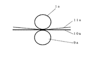
上記の説明において、平板形状の略平面の表面形状を有する押圧転写加工用版1について説明したが、本考案は、これに限定されることなく、押圧転写加工用版1として円柱状や円筒形状のロール状のロールを使用し、そのロールの表面に格子状に区切られた多数個のセルの組み合わせによって表現される微細凹凸形状が表面に刻設されている押圧転写加工用版1も使用できる。または、なめらかに曲げることができるフレキシブル薄板の表面に格子状に区切られた多数個のセルの組み合わせによって表現される微細凹凸形状が表面に刻設されているフレキシブル原版も使用でき、そのフレキシブル原板をロールの表面に巻きつけて固定して構成した押圧転写加工用版1も使用できる。この固定方法としては、例えば、磁力を利用した固定、ボルトなどの固定治具を使用した固定または接着剤を利用した固定などが使用できる。このようなロール形状の押圧転写加工用版を使用した実施例について説明する。図17は本考案の押圧転写加工用版を使用した押圧転写加工装置の一実施例の概略構成図である。図17の押圧転写加工装置は原理的な機構を示すものであり、ロール状の押圧転写加工用版1aと支持部材としてのアンビルロール9aとが対を成して対向し、所定方向に回転している。その押圧転写加工用版1aとアンビルロール9aとの間に被加工物10aと転写箔材料11aが位置する状態で、被加工物10aと転写箔材料11aが繰り出される。本実施例においては、ロールの円周表面が上記に説明した平板形状の表面に相当し、ロールの円周表面に格子状に区切られた多数個のセルの組み合わせによって表現される微細凹凸形状が表面に刻設されている。すなわち、そのロールの表面の展開図が上記説明した押圧転写加工用版に相当する。ロール状の押圧転写加工用版1aとアンビルロール9aとが被加工物10aと転写箔材料11aの速度と同期してこれらを送る方向に回転しながら、それらの間に位置する被加工物10aと転写箔材料11aとを押圧する。これにより、被加工物10aの表面に凹凸パターンの転写画像が転写形成される。転写されなかった残りの転写箔材料11aは他方の方向に運び去られる。
In the above description, the press
また、本考案において、図18に示すような押圧転写加工装置の使用も可能である。図18において、ロール状の押圧転写加工用版1bと平面形状の支持部材9bとが対向し、ロール状の押圧転写加工用版1bが所定方向に回転し、そのロール状の押圧転写加工用版1bの回転と同期して、その押圧転写加工用版1bと支持部材9bとの間に被加工物10bと転写箔材料11bが位置する状態で、被加工物10bと転写箔材料11bが繰り出される。その他の構成および作用は、前述の図16、図17に関する説明と同じである。 Further, in the present invention, it is possible to use a press transfer processing apparatus as shown in FIG. In FIG. 18, the roll-shaped press transfer processing plate 1b and the planar support member 9b face each other, the roll-shaped press transfer processing plate 1b rotates in a predetermined direction, and the roll-shaped press transfer processing plate In synchronism with the rotation of 1b, the workpiece 10b and the transfer foil material 11b are fed out in a state where the workpiece 10b and the transfer foil material 11b are positioned between the press transfer processing plate 1b and the support member 9b. . Other configurations and operations are the same as those described above with reference to FIGS.
転写箔材料を使用しない型押し押圧転写加工装置を使用することも可能である。すなわち、図16の平板状押圧転写加工装置において、支持部材9の上に置かれた被加工物10に対し、所望の文字・模様・文様・図柄・絵柄等の複数種類の画像を刻設した押圧転写加工用版1を固定した熱盤7で支持して配置し、プレス8により上下方向に押圧・離反させて、押圧転写加工用版1に刻設された複数種類の画像を、直接に、被加工物10の表面に直接に転写することも可能である。図17のロール状押圧転写加工装置において、ロール状押圧転写加工用版1aとアンビルロール9aとの間に被加工物10を位置し、押圧転写加工用版1に刻設された複数種類の画像を、直接に、被加工物10の表面に直接に転写することも可能である。この場合、被加工物10は、押圧または押圧・加熱により変形可能な材質である場合に適用でき、例えば、紙類、ダンボール紙、プラスチック成形物、プラスチックフィルム、ゴム類、フェルト類、布類、または、これらを積層した複合材などの被加工物10が適用できる。
It is also possible to use an embossing press transfer processing device that does not use a transfer foil material. That is, in the flat plate press transfer processing apparatus of FIG. 16, a plurality of types of images such as desired characters / patterns / patterns / designs / patterns are engraved on the
このような押圧転写加工用版1を図16に示される押圧転写加工装置に装着、または、ロール状押圧転写加工用版1aを図17に示される押圧転写加工装置に装着して、転写箔材料11を使用して、被加工物10に箔押し押圧転写加工を行い、箔押し転写形成された画像形成体100の模式図が図2に示される。図2において、画像形成体100は、複数種類の転写画像40と複数種類の転写画像を含まない転写背景領域50とを表現し、少なくとも、複数種類の転写画像40を格子状に区切られ、規則性をもって配列された複数種類の転写凹凸パターンセルの組み合わせによって表現する微細凹凸形状が表面に形成されている。本実施例では、複数種類の転写画像40は縦線と横線により格子状に区切られ、縦方向および横方向に規則性をもって配列された複数種類の転写凹凸パターンセルの組み合わせによって微細凹凸形状が表面に形成されている。縦方向または横方向のいずれかひとつを基準線としたとき、前記複数種類の転写凹凸パターンセルは、少なくとも、前記基準線に対して2本以上の平行複数線の凹凸形状で形成された転写鋭角線凹凸パターンセル20と前記基準線に対して2本以上の平行複数線の凹凸形状で形成された転写鈍角線凹凸パターンセル30とを含む互いに異なる角度の2本以上の平行複数線の凹凸形状で形成された転写複数種類の凹凸パターンセルより成る。前記複数種類の転写画像40のそれぞれの転写画像は少なくとも前記転写鋭角線凹凸パターンセル20と前記転写鈍角線凹凸パターンセル30のうちの少なくともひとつの転写凹凸パターンセルを含む転写凹凸パターンセルの組み合わせにより形成されている。または、複数種類の転写画像40のそれぞれの画像は少なくとも転写鋭角線凹凸パターンセル20と転写鈍角線凹凸パターンセル30とを含む前記転写複数種類の凹凸パターンセルの組み合わせにより形成されている。数種類の転写画像40のうちの画像が重なっている転写重なり画像領域がある場合には、その重なっている画像の領域はその重なっているそれぞれの画像を形成する転写凹凸パターンセルのうちの少なくとも1種類ずつの転写凹凸パターンセルの組み合わせから形成されている。
Such a press
すなわち、図2において、(B)、(C)、(D)、(E)、(F)(G)、(H)、(I)、(J)および(K)はそれぞれの転写凹凸パターンセルの拡大図であり、複数種類の転写凹凸パターンセルは互いに異なる傾斜角度の平行複数線を有し、たとえば、(B)、(C)、(D)、(E)および(F)に示されるような転写鋭角線凹凸パターンセル20と、(G)、(H)、(I)、(J)および(K)に示されるような転写鈍角線凹凸パターンセル30とから構成される。なお、図2における転写鋭角線凹凸パターンセル20は、図1における鋭角線凹凸パターンセル2の転写された凹凸パターンセルであり、したがって、転写鋭角線凹凸パターンセル20の傾斜角度の平行複数線は鈍角の平行複数線となるとともに、同様に、転写鈍角線凹凸パターンセル30の傾斜角度の平行複数線は鋭角の平行複数線となる。例えば、それぞれの凹凸パターンセルは3本の平行複数線を構成し、それぞれの平行線の角度は、横線を基準線とした場合、(B)は165度の鈍角であり、(C)は150度の鈍角であり、(D)は135度の鈍角であり、(E)は120度の鈍角であり、(F)は105度の鈍角であり、(G)は75度の鋭角であり、(H)は60度の鋭角であり、(I)は45度の鋭角であり、(J)は30度の鋭角であり、(K)は15度の鋭角である。これらの縦線、横線、鋭角線、鈍角線を表す黒線領域が、使用した押圧転写加工用版の凸部に対応して凹状態に形成され、その他の領域が凸状態に形成されている。なお、上記構成に限定されることなく、縦線と横線が形成されなく各凹凸パターンセルが鋭角線または鈍角線のみにより形成された構成も可能である。また、鋭角線または鈍角線の平行複数線の数が2本または4本以上の平行複数線により形成された構成も可能である。また、縦線、横線、鋭角線、鈍角線を表す黒線領域が凸状態で形成され、その他の領域が凹状態で形成された構成も可能である。また、鋭角線または鈍角線の平行複数線の傾斜角度が前述の傾斜角度に限定されることなく、他の所望の角度で構成された構成も可能である。また、基準線として、縦線を基準線とした構成も可能である。
That is, in FIG. 2, (B), (C), (D), (E), (F) (G), (H), (I), (J), and (K) are the respective transfer uneven patterns. FIG. 4 is an enlarged view of a cell, and a plurality of types of transfer concavo-convex pattern cells have parallel plural lines with different inclination angles, and are shown in, for example, (B), (C), (D), (E), and (F). And a transfer obtuse angle concavo-
複数種類の転写画像40としては、図柄、絵、文字、記号、紋様、写真画像などが適用される。本実施例においては、複数種類の転写画像40としては第1転写画像40aと第2転写画像40bと第3転写画像40cとが形成されている。これらの複数種類の転写画像40と転写背景領域50は複数種類のセルの組み合わせによって表現されて構成されている。すなわち、それぞれの第1転写画像40a,第2転写画像40b,第3転写画像40cは、転写鋭角線凹凸パターンセル20と転写鈍角線凹凸パターンセル30のうちの少なくとも1つの転写凹凸パターンセルを含む組み合わせ、または、少なくとも転写鋭角線凹凸パターンセル20と転写鈍角線凹凸パターンセル30とを含む複数種類の転写凹凸パターンセルの組み合わせにより形成されている。転写背景領域50は、少なくとも転写鋭角線凹凸パターンセル20と転写鈍角線凹凸パターンセル30とを含む複数種類の転写凹凸パターンセルの組み合わせ、または、転写鋭角線凹凸パターンセル20と転写鈍角線凹凸パターンセル30のいずれか1つの転写凹凸パターンセルの組み合わせにより形成されている。第1転写画像40aと第2転写画像40bが重なっている転写重なり画像領域は第1転写画像40aを形成する少なくとも1種類の転写凹凸パターンセルと第2転写画像40bを形成する少なくとも1種類の転写凹凸パターンセルとを含む転写凹凸パターンセルの組み合わせにより形成され、第2転写画像40bと第3転写画像40cが重なっている転写重なり画像領域は第2転写画像40bを形成する少なくとも1種類の転写凹凸パターンセルと第3転写画像40cを形成する少なくとも1種類の転写凹凸パターンセルとを含む転写凹凸パターンセルの組み合わせにより形成され、第1転写画像40aと第3転写画像40cが重なっている転写重なり画像領域は第1転写画像40aを形成する少なくとも1種類の転写凹凸パターンセルと第3転写画像40cを形成する少なくとも1種類の転写凹凸パターンセルとを含む転写凹凸パターンセルの組み合わせにより形成されている。第1転写画像40aと第2転写画像40bと第3転写画像40cが重なっている転写重なり画像領域は第1転写画像40aを形成する少なくとも1種類の転写凹凸パターンセルと第2転写画像40bを形成する少なくとも1種類の転写凹凸パターンセルと第3転写画像40cを形成する少なくとも1種類の転写凹凸パターンセルとを含む転写凹凸パターンセルの組み合わせにより形成されている。なお、上記構成に限定されることなく、転写背景領域50が転写凹凸パターンセルより構成されることなく、凹凸のない平坦形状である構成も可能である。また、複数種類の転写画像40が2種類の転写画像または4種類以上の転写画像である構成も可能である。また、複数種類の転写画像40が重ならないような構成、または、複数種類の転写画像40のうちの任意の数の転写画像が重なっているような構成なども可能である。また、さらなる所望転写画像60が形成され、そのさらなる所望転写画像60が凹凸パターンセルの組み合わせにより形成されることなく、多重直線群、多重曲線群、多重折線群、微細円群、微細多角形群などの微細凹凸形状群、凸状平面形状、凹状平面形状により形成されている構成も可能である。
As the plurality of types of
このような画像形成体は、所望の角度から複数種類の転写画像のうちの所望の画像のみが明瞭に見えるとともに、左右方向及び上下方向、または、横方向及び縦方向などの全方向に見る角度を移動させた場合にも、複数種類の転写画像のうちの1つの画像から他の画像へと明瞭に画像がチェンジングして見える。また、画像の重なり領域においても、全方向に見る角度を移動させた場合にも、複数種類の転写画像のうちの1つの画像から他の画像へと明瞭に画像がチェンジングして見える。特に、従来公知の押圧転写加工用版や画像形成体よりも、それぞれの一つ一つの画像の明瞭性や精細度を著しく向上できる。さらに、画像が重なっている転写重なり領域においても、所定の方向から1つの画像のみが明瞭に見えるとともに、全方向に見る角度を移動させた場合にも、他の画像のみが明瞭に見えるというチェンジング視認効果が、従来の押圧転写加工用版や画像形成体よりも著しく優れる。さらに、より多くの画像が重なって存在する場合にも、このチェンジング視認効果が従来の押圧転写加工用版や画像形成体よりも著しく優れるため、単位領域内により多くの画像を構成できる。 In such an image forming body, only a desired image of a plurality of types of transfer images can be clearly seen from a desired angle, and an angle viewed in all directions such as a horizontal direction and a vertical direction, or a horizontal direction and a vertical direction. Even when the is moved, the image clearly changes from one of the multiple types of transfer images to the other image. Even in the overlapping region of the images, even when the viewing angle is moved in all directions, the image clearly changes from one image of the plurality of types of transfer images to another image. In particular, the clarity and definition of each individual image can be remarkably improved as compared with conventionally known press transfer processing plates and image forming bodies. Furthermore, even in a transfer overlap area where images overlap, only one image can be clearly seen from a predetermined direction, and only the other images can be clearly seen when the viewing angle is moved in all directions. The visual recognition effect is remarkably superior to conventional press transfer processing plates and image forming bodies. Further, even when more images are overlapped, this changing visual recognition effect is remarkably superior to the conventional press transfer processing plate and image forming body, so that more images can be formed in the unit area.
本考案の典型的実施例について以下に説明する。 Exemplary embodiments of the present invention are described below.
実施例1
本考案の典型的実施例の押圧転写加工用版1の概略図を図3に示す。図3において、(A)は平面図であり、押圧転写加工用版1の表面には複数種類の画像が刻設されている。本実施例では複数種類の画像として三角形を形成する第1画像4aとBCD文字を形成する第2画像4bが刻設されている。(B)は第1画像4aの一部分の拡大図であり、(C)は第2画像4bの一部分の拡大図であり、(D)は背景領域5の一部分の拡大図であり、(E)は第1画像4aと第2画像4bとが重なっている重なり領域4abの一部分の拡大図である。(A)において図示を略しているが、押圧転写加工用版1の表面には、互いに直交する縦線と横線により格子状に区切られた複数種類の凹凸パターンセルセルの組み合わせによって表現する微細凹凸形状の複数種類の凹凸パターンセルが刻設されている。横線を基準線としたとき、複数種類の凹凸パターンセルは、基準線に対して鋭角(30度)の平行複数線の凹凸形状で刻設された第1鋭角線凹凸パターンセル2aと、第1鋭角線凹凸パターンセル2aと異なる鋭角(60度)の平行複数線の凹凸形状で刻設された第2鋭角線凹凸パターンセル2bと、基準線に対して鈍角(150度)の平行複数線の凹凸形状で刻設された第1鈍角線凹凸パターンセル3aと、第1鈍角線凹凸パターンセル3aと異なる鈍角(120度)の平行複数線の凹凸形状で刻設された第2鈍角線凹凸パターンセル3bとからなる。(B)に示されるように第1画像4aは第1鋭角線凹凸パターンセル2aと第2鈍角線凹凸パターンセル3bとが縦方向及び横方向に交互に位置するように組み合わされて形成され、(C)に示されるように第2画像4bは第2鋭角線凹凸パターンセル2bと第1鈍角線凹凸パターンセル3aとが縦方向及び横方向に交互に位置するように組み合わされて形成され、(E)に示されるように第1画像と前記第2画像とが重なる重なり画像領域4abは第1鋭角線凹凸パターンセル2aと第1鈍角線凹凸パターンセル3aとが縦方向及び横方向に交互に位置するように組み合わされて形成されている。(D)に示されるように第1画像と第2画像とを含まない背景領域5は第2鋭角線凹凸パターンセル2bと第2鈍角線凹凸パターンセル3bとが縦方向及び横方向に交互に位置するように組み合わされて形成されている。
Example 1
FIG. 3 shows a schematic diagram of a
すなわち、図3に示される押圧転写加工用版1の構成において、押圧転写加工用版1は、複数種類の画像4と背景領域5とが格子状に区切られた複数種類のセルの組み合わせによって表現されている。複数種類の画像4が第1画像4aと第2画像4bの2種類の画像であるとき、複数種類の凹凸パターンセルは、基準線に対して0度から45度までの範囲の鋭角の平行複数線の凹凸形状で刻設された第1鋭角線凹凸パターンセル2aと、基準線に対して45度から90度までの範囲であって第1鋭角線凹凸パターンセルと異なる鋭角の平行複数線の凹凸形状で刻設された第2鋭角線凹凸パターンセル2bと、基準線に対して135度から180度までの範囲の鈍角の平行複数線の凹凸形状で刻設された第1鈍角線凹凸パターンセル3aと、基準線に対して90度から135度までの範囲であって第1鈍角線凹凸パターンセルと異なる鈍角の平行複数線の凹凸形状で刻設された第2鈍角線凹凸パターンセル3bとからなる。第1画像4aは前記第1鋭角線凹凸パターンセル2aと第2鈍角線凹凸パターンセル3bとが縦方向及び横方向に交互に位置するように組み合わされて形成され、第2画像4bは第2鋭角線凹凸パターンセル2bと前記第1鈍角線凹凸パターンセル3aとが縦方向及び横方向に交互に位置するように組み合わされて形成され、第1画像と第2画像とが重なる重なり画像領域は第1鋭角線凹凸パターンセル2aと第1鈍角線凹凸パターンセル3aとが縦方向及び横方向に交互に位置するように組み合わされて形成され、第1画像と第2画像とを含まない背景領域5は第2鋭角線凹凸パターンセル2bと第2鈍角線凹凸パターンセル3bとが縦方向及び横方向に交互に位置するように組み合わされて形成されている。
That is, in the configuration of the press
図3において、押圧転写加工用版1の材質は真鍮製であり、その形状は、平面図において横長さが80mm、縦長さが50mmの長方形である。表面に刻設形成された格子状に区切られたそれぞれのセルの形状は、縦長さおよび横長さがそれぞれ0.3mmの正方形である。それぞれのセルには所定の傾斜角度の2本の平行線が形成され、その平行線のピッチ間隔は約0.1mmである。縦線、横線、平行傾斜角度線などの黒線部が凸状態で形成され、黒線以外の部分は凹状態で形成され、その凸部と凹部との高低差は約0.02mmである。凸部の平行線の線幅は約0.04mmであり、凸部の格子状線の線幅は約0.02mmである。このような押圧転写加工用版1は、前述の腐蝕エッチング加工方法によって、精度よく作製される。
In FIG. 3, the material of the press
図16に示される押圧転写加工装置に、図3に示される押圧転写加工用版1を装着して、ベースフィルム層と転写箔層とを有する転写箔材料11と、被加工物10としての厚紙を使用して、箔押し押圧転写加工を行う場合における押圧転写加工用版1と転写箔材料11と被加工物10との関係の断面形状を説明するための模式図を図4に示す。図4において、(A)は箔押し押圧転写加工を行う直前の断面模式図であり、(B)は押圧転写加工用版1が転写箔材料11を被加工物10に押圧したときの状態の断面模式図を示し、(C)は、箔押し押圧転写加工を行った後の被加工物10の断面模式図を示す。図3において、(A)の状態に位置する押圧転写加工用版1が、(B)のように転写箔材料11を被加工物10に押圧することにより、押圧転写加工用版1の表面に刻設された凹凸パターンの形状に対応して、転写箔材料11の転写箔層が被加工物10に接着するとともに凹凸形状に転写形成され、その結果、(C)のように被加工物10の表面に接着されるとともに凹凸パターン形状に転写形成された転写箔層の箔押しされた転写パターンが形成される。なお、被加工物10が繊維製フェルトなどの厚く軟らかい材料である場合、凹凸形状に転写形成されるとともに、被加工物10の表面も凹凸形状に転写形成される。また、図4(C)に示される凹凸パターン形状に転写形成された転写箔層の凸部の断面形状において丸みを帯びているが、この断面形状に限定されることなく、例えば、厚い厚さの転写箔材料11を使用した場合または押圧転写加工用版1に刻設された凹凸パターンの凹凸部が被加工物10の表面から深く入り込むような被加工物10を使用した場合には、押圧転写加工用版1に刻設された凹凸パターンの深さ方向の凹凸形状に忠実に凹凸形成された箔押しされた転写パターンが転写形成される。
A press
図4と図16において、被加工物10としての厚紙の表面に、押圧転写加工用版1に刻設された凹凸パターン形状に対応して箔押し転写パターンが凹凸形状で箔押転写形成される。この場合、ベースフィルム層と被加工物側に転写されなかった残りの転写箔層とを含むベースフィルム層付転写箔材料11は、他方の送受ロール12により巻き取られる。転写箔材料11としては、例えば、ベースフィルム層・離型層・表面保護層・着色層・金属層・接着層とから構成され、ベースフィルム層(約0.01mm−0.05mm厚)と転写箔層とからなる転写箔材料が使用できる。ここで、ベースフィルム層はキャリアフィルム層とも呼ばれ、ポリエステルフィルムなどの強靭なフィルムが使用される。転写箔層は例えば、表面保護層・着色層・金属層・接着層から構成される。着色層としては、染料や顔料などの着色剤含有材や着色フィルム層などが使用される。表面保護層としては、透明または着色された塗料やプラスチックフィルムが使用される。金属層としては金属蒸着層、金属薄膜層、金属蒸着フィルム層または金属箔層などが使用される。接着層は対象となる被加工物に接着しやすい材質の接着剤より構成される。離型層は、ベースフィルム層側または転写箔層側に形成される。これらの金属層の金属の種類や着色層の色の種類を組み合わせることによって、「金色」、「銀色」、「メタリックブルー」、「メタリックピンク」などの所望の色を呈する転写箔材料11が得られる。このような転写箔材料11を使用した場合、転写箔層(表面保護層・着色層・金属層・接着層)の接着層側が被加工物の表面に接着されて箔押転写形成される。本実施例では、「金色」を呈する転写箔材料11を使用した場合について説明する。
4 and 16, a foil press transfer pattern is formed on the surface of a thick paper as the
このようにして箔押し転写形成された画像形成体100の模式図が図5に示される。図5において、(A)は画像形成体100の表面の平面模式図であり、(B)は第1転写画像40aの部分拡大模式図であり、(C)は第2転写画像40bの部分拡大模式図であり、(D)は背景転写画像領域50の部分拡大模式図であり、(E)は第1転写画像と第2転写画像との重なり転写画像領域40abの一部分の拡大模式図である。図5の(B)、(C)、(D)、(E)において、使用した押圧転写加工用版1に刻設された凹凸パターン形状に対応して、黒線部が凹状態で転写形成され、黒線以外の部分が凸状態で転写形成されている。横線を基準線としたとき、複数種類の転写凹凸パターンセルは、第1鋭角線凹凸パターンセル2aに対応して転写形成された第1転写鋭角線凹凸パターンセル20aと、第2鋭角線凹凸パターンセル2bに対応して転写形成された第2転写鋭角線凹凸パターンセル20bと、第1鈍角線凹凸パターンセル3aに対応して転写形成された第1転写鈍角線凹凸パターンセル30aと、第2鈍角線凹凸パターンセル3bに対応して転写形成された第2転写鈍角線凹凸パターンセル30bとからなる。なお、それぞれの傾斜角度線は、転写形成されるために鋭角と鈍角とが逆に形成される。すなわち、第1転写鋭角線凹凸パターンセル20aと第2転写鋭角線凹凸パターンセル20bは鈍角線として転写形成され、第1転写鈍角線凹凸パターンセル30aと第2転写鈍角線凹凸パターンセル30bは鋭角線として転写形成される。
FIG. 5 shows a schematic diagram of the
(B)に示されるように、第1転写画像40aは第1転写鋭角線凹凸パターンセル20aと第2転写鈍角線凹凸パターンセル30bとが縦方向および横方向に交互に位置するように構成される。(C)に示されるように、第2転写画像40bは第2転写鋭角線凹凸パターンセル20bと第1転写鈍角線凹凸パターンセル30aとが縦方向および横方向に交互に位置するように構成される。(D)に示されるように、背景転写画像領域50は第2転写鋭角線凹凸パターンセル20bと第2転写鈍角線凹凸パターンセル30bとが縦方向および横方向に交互に位置するように構成される。(E)に示されるように、第1転写画像と第2転写画像との転写重なり画像領域40abは第1転写鋭角線凹凸パターンセル20aと第1転写鈍角線凹凸パターンセル30aとが縦方向および横方向に交互に位置するように構成される。すなわち、複数種類の転写画像40と転写背景領域50とが格子状に区切られた複数種類の転写凹凸パターンセルの組み合わせによって表現され、複数種類の転写画像40が第1転写画像40aと第2転写画像40bの2種類の転写画像であるとき、複数種類の転写凹凸パターンセルは、前記基準線に対して鈍角の平行複数線の凹凸形状で刻設された第1転写鋭角線凹凸パターンセル20aと、第1転写鋭角線凹凸パターンセルと異なる鈍角の平行複数線の凹凸形状で刻設された第2転写鋭角線凹凸パターンセル20bと、前記基準線に対して鋭角の平行複数線の凹凸形状で刻設された第1転写鈍角線凹凸パターンセル30aと、前記第1鈍角線凹凸パターンセルと異なる鋭角の平行複数線の凹凸形状で刻設された第1転写鈍角線凹凸パターンセル30bとからなり、第1転写画像40aは第1転写鋭角線凹凸パターンセル20a(傾斜角150度)と第2転写鈍角線凹凸パターンセル30b(傾斜角60)とが縦方向及び横方向に交互に位置するように組み合わされて形成され、第2転写画像40bは第2転写鋭角線凹凸パターンセル20b(傾斜角120度)と第1転写鈍角線凹凸パターンセル30a(傾斜角30度)とが縦方向及び横方向に交互に位置するように組み合わされて形成され、第1転写画像と第2転写画像とが重なる転写重なり画像領域40abは第1転写鋭角線凹凸パターンセル20a(傾斜角150度)と第1転写鈍角線凹凸パターンセル30a(傾斜角30度)とが縦方向及び横方向に交互に位置するように組み合わされて形成され、第1転写画像と第2転写画像とを含まない転写背景領域50は第2転写鋭角線凹凸パターンセル20b(傾斜角120度)と第2転写鈍角線凹凸パターンセル30b(傾斜角60度)とが縦方向及び横方向に交互に位置するように組み合わされて形成されている。
As shown in (B), the first transfer image 40a is configured such that the first transfer acute angle line
このようにして凹凸形状で転写形成された画像形成体100の転写形成された転写箔層は光沢表面を呈し、その転写形成された画像形成体100を、左右方向または横方向に視線を動かして見たとき、第1転写画像40aのみが明瞭に見える視線角度があり、また、第2転写画像40bのみが明瞭に見える視線角度があり、第1転写画像40aと第2転写画像40bが不明瞭にぼやけて見える視線角度がある。さらに、その画像形成体100を、上下方向または縦方向に視線を動かして見たとき、第1転写画像40aのみが明瞭に見える視線角度があり、また、第2転写画像40bのみが明瞭に見える視線角度があり、また、第1転写画像40aと第2転写画像40bが不明瞭にぼやけて見える視線角度がある。特に、第1転写画像40aと第2転写画像40bとが重なる転写重なり画像領域40abにおいても、所望の角度からは、2つの画像のうちの一つの転写画像のみが明瞭に見える。このように、箔押し転写形成された画像形成体100を左右方向および上下方向、または、横方向および縦方向に視線を動かして見たとき、第1転写画像40aのみが明瞭に視認できる視線角度があり、また、第2転写画像40bのみが明瞭に視認できる視線角度がある。すなわち、所望の角度から複数種類の画像のうちの1つの画像が明瞭に見えるとともに、左右方向または横方向、及び、上下方向または縦方向の全方向に見る角度を移動させた場合にも、1つの画像から他の画像へと見えるチェンジング画像が明瞭に変化して見える。さらに、画像の重なり領域においても、全方向に見る角度を移動させた場合にも、複数種類の転写画像のうちの1つの画像から他の画像へと明瞭に画像がチェンジングして見える。
The transferred transfer foil layer of the
なお、本実施例において、転写箔材料11の転写箔層として、表面保護層・着色層・金属層・接着層からなる構成を例示したが、これに限定されることなく、箔押により転写形成できる所定の構成からなる転写箔層が使用できる。また、被加工物10としては、本実施例においては厚紙を使用したが、これに限定されることなく、例えば、通常の紙類、レター用紙、便箋、ノート表紙、カード、ラベル、繊維織物、繊維製フェルト、布、不織布等、樹脂コートされた紙類、防水コートされた紙類、プラスチックフィルムとラミネートされた紙類、プラスチックフィルムシート、皮革製品、プラスチック薄板、金属薄板、ラミネートフィルム、プラスチック製シート、プラスチック成形品、などが使用される。
In the present embodiment, the transfer foil layer of the transfer foil material 11 is exemplified by a structure composed of a surface protective layer, a colored layer, a metal layer, and an adhesive layer. However, the transfer foil layer is formed by stamping without being limited thereto. A transfer foil layer having a predetermined configuration can be used. Further, as the
本実施例においては、図3の押圧転写加工用版1の(B)、(C)、(D)、(E)に示されるそれぞれの凹凸パターンセルの黒線部が凸状に刻設されているが、これに限定されることなく、その黒線部が凹状に刻設された構成も可能である。このように、押圧転写加工用版1に刻設された凹凸が逆の押圧転写加工用版1を使用して転写形成された画像形成体も、上記説明と同じ優れた作用効果を発揮する。また、この場合、押圧転写加工用版1の腐蝕エッチング製造工程において、ネガ型レジストとポジ型レジストの種類、露光用マスクとなる原版フィルムの透明部と遮光部の構成、などを適切に適用することによって所望の凹凸形状を有する凹凸パターンセルを製造することができる。
In the present embodiment, the black line portions of the concavo-convex pattern cells shown in (B), (C), (D), and (E) of the
本実施例においては、第1画像4aが三角形であり、第2画像がBCD文字である例を示したが、これらの画像に限定されることなく、任意の文字、絵柄、記号、図柄、写真柄、文様、これらの組み合わせなどの任意の所望の画像を形成するように刻設した押圧転写加工用版1を使用することもできる。また、本実施例では、縦線と横線により格子状に区切られた正方形の凹凸パターンセルの中に所定傾斜角度の平行複数線を刻設した実施例について説明したが、この構成に限定されることなく、図15の(A)に示されるような菱形正四角形の凹凸パターンセル、(B)に示されるような長方形の凹凸パターンセル、(C)に示されるような平行四辺形の凹凸パターンセル、などの規則性を持って配列した格子状に区切られた凹凸パターンセルに区切られて、このような多角形の凹凸パターンセルの中に、所定の傾斜角度の平行複数線が凹凸形状で刻設されたような構成も可能であり、この場合にも、本実施例と同じ効果を発揮する。
In the present embodiment, the
実施例2
本考案の他の実施例の押圧転写加工用版は、複数種類の画像4と背景領域5とが格子状に区切られた前記複数種類のセルの組み合わせによって表現され、複数種類の画像4が第1画像から第n画像までのn種類の画像であるとき、複数種類の凹凸パターンセルは、鋭角線凹凸パターンセル2と鈍角線凹凸パターンセル3とを含む互いに異なる角度の平行複数線の凹凸形状で刻設された第1凹凸パターンセルから第(n+1)凹凸パターンセルまでの(n+1)種類の凹凸パターンセルが用いられ、n種類の画像のそれぞれの画像には、それぞれの角度の平行複数線の凹凸形状で刻設された凹凸パターンセルが割り当てられ、n種類の画像のそれぞれの画像が単独で存在する領域は、それぞれの画像に割り当てられた前記第1凹凸パターンセルから第n凹凸パターンセルまでの凹凸パターンセルのいずれか1つの凹凸パターンセルと前記第(n+1)凹凸パターンセルとが縦方向及び横方向に交互に位置するように組み合わされて形成され、n種類の画像の2つ以上が重なっている重なり画像領域は、その重なっている領域の画像に割り当てられた凹凸パターンセルのすべての凹凸パターンセルが縦方向及び横方向に互いに異なる凹凸パターンセルが隣り合うように位置して組み合わされて形成され、n種類の画像のいずれの画像も含まない背景領域は、前記第(n+1)凹凸パターンセルだけからなるように位置して組み合わされて形成されていることを特徴とする。
Example 2
A plate for press transfer processing according to another embodiment of the present invention is expressed by a combination of a plurality of types of cells in which a plurality of types of
本実施例の具体的実施例の押圧転写加工用版の概略模式図が図6に示される。図6において、n種類の複数種類の画像としては2種類の画像が形成され、(n+1)種類の複数種類の凹凸パターンセルとしては、3種類の凹凸パターンセルが形成されている実施例である。図6において、(A)は平面図であり、押圧転写加工用版1の表面にはn種類の画像としての円形を形成する第1画像4aとEFG反転文字を形成する第2画像4bの2種類の画像が形成されている。(B)は第1画像4aの一部分の拡大図であり、(C)は第2画像4bの一部分の拡大図であり、(D)は背景領域5の一部分の拡大図であり、(E)は第1画像4aと第2画像4bとが重なっている重なり領域4abの一部分の拡大図である。(n+1)種類の複数種類の凹凸パターンセルとして、傾斜角度が30度の3本の平行線を刻設した第1鋭角凹凸パターンセル2aと、傾斜角度が60度の3本の平行線を刻設した第2鋭角凹凸パターンセル2bと、傾斜角度が150度の3本の平行線を刻設した第1鈍角凹凸パターンセル3aの3種類の凹凸パターンセルが刻設されている。本実施例では、格子状に区切るための縦線と横線は形成されていないが、縦横に格子状に区切られたそれぞれのセルには、所定傾斜角度の複数平行線が刻設されている。図6(B)に示されるように、第1画像4aは、傾斜角度30度の平行線を刻設した第1鋭角凹凸パターンセル2aと傾斜角度60度の平行線を刻設した第2鋭角凹凸パターンセル2bとが縦方向及び横方向に交互に位置するように構成されている。図6(C)に示されるように、第2画像4bは、傾斜角度150度の平行線を刻設した第1鈍角凹凸パターンセル3aと傾斜角度60度の平行線を刻設した第2鋭角凹凸パターンセル2bとが縦方向及び横方向に交互に位置するように構成されている。図6(D)に示されるように、背景領域5は、傾斜角度60度の平行線を刻設した第2鋭角凹凸パターンセル2bが縦方向及び横方向に位置するように構成されている。図6(E)に示されるように、第1画像4aと第2画像4bが重なっている重なり画像領域4abは、傾斜角度30度の平行線を刻設した第1鋭角凹凸パターンセル2aと傾斜角度150度の平行線を刻設した第1鈍角凹凸パターンセル3aとが縦方向及び横方向に交互に位置するように構成されている。すなわち、背景領域5は1種類の凹凸パターンセル2bのみから形成され、第1画像が単独で存在する領域4aは背景領域を形成する凹凸パターンセル2bと第1画像に割り当てられた凹凸パターンセル2aとの組み合わせから形成され、第2画像が単独で存在する領域4bは背景領域を形成する凹凸パターンセル2bと第2画像に割り当てられた凹凸パターンセル3aとの組み合わせから形成され、第1画像と第2画像とが重なる領域4abは第1画像に割り当てられた凹凸パターンセル2aと第2画像に割り当てられた凹凸パターンセル3aとの組み合わせから形成される。
FIG. 6 shows a schematic diagram of a plate for press transfer processing according to a specific example of this example. In FIG. 6, two types of images are formed as n types of images, and three types of concavo-convex pattern cells are formed as (n + 1) types of concavo-convex pattern cells. . In FIG. 6, (A) is a plan view. On the surface of the
本実施例において、押圧転写加工用版の材質は鋼鉄製であり、その形状は、平面図において横長さが105mm、縦長さが65mmの長方形である。図6において、表面に刻設形成された格子状に区切られたそれぞれのセルの形状は、縦長さおよび横長さがそれぞれ0.5mmの正方形である。それぞれのセルには所定の傾斜角度の3本の平行傾斜角度線が形成され、その平行傾斜角度線のピッチ間隔は約0.15mmである。平行傾斜角度線などの黒線部が凸状態で形成され、黒線以外の部分は凹状態で形成され、その凸部と凹部との高低差は約0.015mmであり、凸部の平行傾斜角度線の線幅は約0.06mmである。このような押圧転写加工用版1aは、前述の腐蝕エッチング加工方法によって、精度よく作製される。その他については実施例1で説明した内容と同じである。
In this embodiment, the material of the press transfer processing plate is made of steel, and the shape thereof is a rectangle having a horizontal length of 105 mm and a vertical length of 65 mm in the plan view. In FIG. 6, the shape of each cell partitioned into a lattice shape formed on the surface is a square having a vertical length and a horizontal length of 0.5 mm. Each cell is formed with three parallel inclination angle lines having a predetermined inclination angle, and the pitch interval of the parallel inclination angle lines is about 0.15 mm. The black line part such as the parallel inclination angle line is formed in a convex state, the part other than the black line is formed in a concave state, and the height difference between the convex part and the concave part is about 0.015 mm, and the parallel inclination of the convex part The line width of the angle line is about 0.06 mm. Such a press
このような押圧転写加工用版1を図16に示される押圧転写加工装置に装着して、ベースフィルム層と転写箔層とを有する転写箔材料11と、被加工物10としての不織布を使用して、箔押し押圧転写加工を行い、箔押し転写形成された画像形成体100の模式図が図7に示される。なお、転写箔材料11としては、被加工物10としての不織布に適正に転写形成できる転写箔材料11が使用される。図7において、(A)は画像形成体100の表面の平面模式図である。(B)は第1転写画像40aの部分拡大模式図であり、第1転写画像40aは第1転写鋭角線凹凸パターンセル20aと第2転写鋭角線凹凸パターンセル20bとが縦方向および横方向に交互に位置して形成されている。(C)は第2転写画像40bの部分拡大模式図であり、第2転写画像40bは第1転写鈍角線凹凸パターンセル30aと第2転写鋭角線凹凸パターンセル20bとが縦方向および横方向に交互に位置して形成されている。(D)は背景転写画像50の部分拡大模式図であり、背景転写画像50は第2転写鋭角線凹凸パターンセル20bから形成されている。(E)は第1転写画像と第2転写画像との転写重なり画像領域40abの一部分の拡大模式図であり、転写重なり画像領域40abは第1転写鋭角線凹凸パターンセル20aと第1転写鈍角線凹凸パターンセル30aとが縦方向および横方向に交互に位置して形成されている。図7の(B)、(C)、(D)、(E)において、使用した押圧転写加工用版1に刻設された凹凸パターン形状に対応して、黒線部が凹状態で転写形成され、黒線以外の部分が凸状態で転写形成されている。すなわち、画像形成体100は複数種類の転写画像40と転写背景領域50とが格子状に区切られた複数種類の転写凹凸パターンセルの組み合わせによって表現され、複数種類の転写画像40が第1画像から第n画像までのn種類の転写画像であるとき、複数種類の転写凹凸パターンセルは、転写鋭角線凹凸パターンセル20と転写鈍角線凹凸パターンセル30とを含む互いに異なる角度の平行複数線の凹凸形状で刻設された第1転写凹凸パターンセルから第(n+1)転写凹凸パターンセルまでの(n+1)種類の転写凹凸パターンセルが用いられ、n種類の転写画像のそれぞれの転写画像には、それぞれの角度の平行複数線の凹凸形状で刻設された転写凹凸パターンセルが割り当てられ、n種類の転写画像のそれぞれの転写画像が単独で存在する領域は、それぞれの転写画像に割り当てられた第1転写凹凸パターンセルから第n転写凹凸パターンセルまでの転写凹凸パターンセルのいずれか1つの転写凹凸パターンセルと第(n+1)転写凹凸パターンセルとが縦方向及び横方向に交互に位置するように組み合わされて形成され、n種類の転写画像の2つ以上が重なっている転写重なり画像領域は、その重なっている領域の転写画像に割り当てられた転写凹凸パターンセルのすべての転写凹凸パターンセルが縦方向及び横方向に互いに異なる凹凸パターンセルが隣り合うように位置して組み合わされて形成され、n種類の転写画像のいずれの画像も含まない転写背景領域は、第(n+1)転写凹凸パターンセルだけからなるように位置して組み合わされて形成されている。
Such a press
このようにして凹凸形状で転写形成された画像形成体100の転写形成された転写箔層は光沢表面を呈し、その転写形成された画像形成体100を、左右方向または横方向、および、上下方向または縦方向に視線を動かして見たとき、第1転写画像40aのみが明瞭に見える視線角度があり、また、第2転写画像40bのみが明瞭に見える視線角度があり、第1転写画像40aと第2転写画像40bが不明瞭にぼやけて見える視線角度がある。特に、第1転写画像40aと第2転写画像40bとが重なる転写重なり画像領域40abにおいても、所望の角度からは、2つの画像のうちの一つの転写画像のみが明瞭に見える。このように、所望の角度から複数種類の画像のうちの1つの画像が明瞭に見えるとともに、左右方向または横方向、及び、上下方向または縦方向の全方向に見る角度を移動させた場合にも、1つの画像から他の画像へと見えるチェンジング画像が明瞭に変化して見える。さらに、画像の重なり領域においても、全方向に見る角度を移動させた場合にも、複数種類の転写画像のうちの1つの画像から他の画像へと明瞭に画像がチェンジングして見える。
The transfer-formed transfer foil layer of the
実施例3
本考案の他の実施例の具体的実施例の押圧転写加工用版の概略図が図8に示される。本実施例の押圧転写加工用版1は、実施例2の押圧転写加工用版において、n種類の複数種類の画像4として3種類の画像が形成され、(n+1)種類の複数種類の凹凸パターンセルとして4種類の凹凸パターンセルが形成されている実施例である。図8において、(A)は平面図であり、押圧転写加工用版1の表面には円形を形成する第1画像4aと三角形を形成する第2画像4bとEFG反転文字を形成する第3画像4cの3種類の画像が形成されている。(B)は第1画像4aの一部分の拡大図であり、(C)は第2画像4bの一部分の拡大図であり、(D)は第3画像4cの一部分の拡大図であり、(E)は背景領域5の一部分の拡大図であり、(F)は第1画像4aと第2画像4bとが重なっている重なり画像領域4abの一部分の拡大図であり、(G)は第2画像4bと第3画像4cとが重なっている重なり画像領域4bcの一部分の拡大図であり、(H)は第1画像4aと第3画像4cとが重なっている重なり画像領域4acの一部分の拡大図である。(I)は第1画像4aと第2画像4bと第3画像4cとが重なっている重なり画像領域4abcの一部分の拡大図である。(n+1)種類の複数種類の凹凸パターンセルとして、傾斜角度が30度の3本の平行線を刻設した第1鋭角凹凸パターンセル2aと、傾斜角度が60度の3本の平行線を刻設した第2鋭角凹凸パターンセル2bと、傾斜角度が150度の3本の平行線を刻設した第1鈍角凹凸パターンセル3aと、傾斜角度が120度の3本の平行線を刻設した第2鈍角凹凸パターンセル3bの4種類の凹凸パターンセルが刻設されている。本実施例では、格子状に区切るための縦線と横線が形成されている。
Example 3
FIG. 8 shows a schematic view of a press transfer processing plate according to a specific embodiment of another embodiment of the present invention. In the press-
図8(B)に示されるように、第1画像4aは、傾斜角度30度の平行線を刻設した第1鋭角凹凸パターンセル2aと傾斜角度60度の平行線を刻設した第2鋭角凹凸パターンセル2bとが縦方向及び横方向に交互に位置するように構成されている。図8(C)に示されるように、第2画像4bは、傾斜角度150度の平行線を刻設した第1鈍角凹凸パターンセル3aと傾斜角度60度の平行線を刻設した第2鋭角凹凸パターンセル2bとが縦方向及び横方向に交互に位置するように構成されている。図8(D)に示されるように、第3画像4cは、傾斜角度120度の平行線を刻設した第2鈍角凹凸パターンセル3bと傾斜角度60度の平行線を刻設した第2鋭角凹凸パターンセル2bとが縦方向及び横方向に交互に位置するように構成されている。図8(E)に示されるように、背景領域5は、傾斜角度60度の平行線を刻設した第2鋭角凹凸パターンセル2bが縦方向及び横方向に位置するように構成されている。図8(F)に示されるように、第1画像4aと第2画像4bが重なっている重なり画像領域4abは、傾斜角度30度の平行線を刻設した第1鋭角凹凸パターンセル2aと傾斜角度150度の平行線を刻設した第1鈍角凹凸パターンセル3aとが縦方向及び横方向に交互に位置するように構成されている。図8(G)に示されるように、第2画像4bと第3画像4cが重なっている重なり画像領域4bcは、傾斜角度150度の平行線を刻設した第1鈍角凹凸パターンセル3aと傾斜角度120度の平行線を刻設した第2鈍角凹凸パターンセル3bとが縦方向及び横方向に交互に位置するように構成されている。図8(H)に示されるように、第1画像4aと第3画像4cが重なっている重なり画像領域4acは、傾斜角度30度の平行線を刻設した第1鋭角凹凸パターンセル2aと傾斜角度120度の平行線を刻設した第2鈍角凹凸パターンセル3bとが縦方向及び横方向に交互に位置するように構成されている。図8(I)に示されるように、第1画像4aと第2画像4bと第3画像4cが重なっている重なり画像領域4abcは、傾斜角度30度の平行線を刻設した第1鋭角凹凸パターンセル2aと傾斜角度150度の平行線を刻設した第1鈍角凹凸パターンセル3aと傾斜角度120度の平行線を刻設した第2鈍角凹凸パターンセル3bが縦方向及び横方向に交互に位置するように構成されている。すなわち、背景領域5は1種類の凹凸パターンセル2bのみから形成され、第1画像が単独で存在する領域4aは背景領域を形成する凹凸パターンセル2bと第1画像に割り当てられた凹凸パターンセル2aとの組み合わせから形成され、第2画像が単独で存在する領域4bは背景領域を形成する凹凸パターンセル2bと第2画像に割り当てられた凹凸パターンセル3aとの組み合わせから形成され、第3画像が単独で存在する領域4cは背景領域を形成する凹凸パターンセル2bと第3画像に割り当てられた凹凸パターンセル3bとの組み合わせから形成される。第1画像と第2画像とが重なる重なり画像領域4abは第1画像に割り当てられた凹凸パターンセル2aと第2画像に割り当てられた凹凸パターンセル3aとの組み合わせから形成され、第2画像と第3画像とが重なる重なり画像領域4bcは第2画像に割り当てられた凹凸パターンセル3aと第3画像に割り当てられた凹凸パターンセル3bとの組み合わせから形成され、第1画像と第3画像とが重なる重なり画像領域4acは第1画像に割り当てられた凹凸パターンセル2aと第3画像に割り当てられた凹凸パターンセル3bとの組み合わせから形成される。また、第1画像と第2画像と第3画像とが重なる重なり画像領域4abcは第1画像に割り当てられた凹凸パターンセル2aと第2画像に割り当てられた凹凸パターンセル3aと第3画像に割り当てられた凹凸パターンセル3bとの組み合わせから形成される。
As shown in FIG. 8B, the
本実施例において、押圧転写加工用版1の材質は銅製であり、その形状は、平面図において横長さが105mm、縦長さが65mmの長方形である。表面に刻設形成された格子状に区切られたそれぞれのセルの形状は、縦長さおよび横長さがそれぞれ0.5mmの正方形である。それぞれのセルには所定の傾斜角度の3本の平行傾斜角度線が形成され、その平行傾斜角度線のピッチ間隔は約0.15mmである。平行傾斜角度線などの黒線部が凹状態で形成され、黒線以外の部分は凸状態で形成され、その凸部と凹部との高低差は約0.015mmであり、凹部の平行傾斜角度線の線幅は約0.09mmであり、凹部の縦線・横線の線幅は約0.07mmである。このような押圧転写加工用版1は、前述の腐蝕エッチング加工方法によって、精度よく作製される。その他については実施例1で説明した内容と同じである。
In the present embodiment, the material of the press
このような押圧転写加工用版と図16に示される押圧転写加工装置に装着して、転写箔材料を使用することなく、被加工物の表面に直接に押圧転写加工を行った場合の転写形成された画像形成体の模式図が図9に示される。この場合、被加工物の一例として、金色に着色された光沢表面を有するプラスチックフィルムと紙との積層物が使用される。このようなプラスチックフィルム・紙積層物の所定の領域に転写形成された画像形成体の模式図が図9である。図9において、(A)は画像形成体100の表面の平面模式図である。(B)は第1転写画像40aの部分拡大模式図であり、第1転写画像40aは第1転写鋭角線凹凸パターンセル20aと第2転写鋭角線凹凸パターンセル20bとが縦方向および横方向に交互に位置して形成されている。(C)は第2転写画像40bの部分拡大模式図であり、第2転写画像40bは第1転写鈍角線凹凸パターンセル30aと第2転写鋭角線凹凸パターンセル20bとが縦方向および横方向に交互に位置して形成されている。(D)は第3転写画像40cの部分拡大模式図であり、第3転写画像40cは第2転写鈍角線凹凸パターンセル30bと第2転写鋭角線凹凸パターンセル20bとが縦方向および横方向に交互に位置して形成されている。(E)は転写背景画像50の部分拡大模式図であり、転写背景画像50は第2転写鋭角線凹凸パターンセル20bから形成されている。(F)は第1転写画像と第2転写画像との転写重なり画像領域40abの一部分の拡大模式図であり、転写重なり画像領域40abは第1転写鋭角線凹凸パターンセル20aと第1転写鈍角線凹凸パターンセル30aとが縦方向および横方向に交互に位置して形成されている。(G)は第2転写画像と第3転写画像との転写重なり画像領域40bcの一部分の拡大模式図であり、転写重なり画像領域40bcは第1転写鈍角線凹凸パターンセル30aと第2転写鈍角線凹凸パターンセル30bとが縦方向および横方向に交互に位置して形成されている。(H)は第1転写画像と第3転写画像との転写重なり画像領域40acの一部分の拡大模式図であり、転写重なり画像領域40acは第1転写鋭角線凹凸パターンセル20aと第2転写鈍角線凹凸パターンセル30bとが縦方向および横方向に交互に位置して形成されている。(I)は第1転写画像と第2転写画像と第3転写画像との転写重なり画像領域40abcの一部分の拡大模式図であり、転写重なり画像領域40abcは第1転写鋭角線凹凸パターンセル20aと第1転写鈍角線凹凸パターンセル30aと第2転写鈍角線凹凸パターンセル30bとが縦方向および横方向に交互に位置して形成されている。図9の(B)、(C)、(D)、(E)、(F)、(G)、(H)、(I)において、使用した押圧転写加工用版1に刻設された凹凸パターン形状に対応して、黒線部が凹状態で転写形成され、黒線以外の部分が凹状態で転写形成されている。
Transfer formation when such a press-transfer processing plate and the press-transfer processing apparatus shown in FIG. 16 are mounted and the press-transfer processing is directly performed on the surface of the workpiece without using a transfer foil material. A schematic diagram of the formed image forming body is shown in FIG. In this case, a laminate of a plastic film and paper having a glossy surface colored in gold is used as an example of a workpiece. FIG. 9 is a schematic view of an image forming body transferred and formed in a predetermined region of such a plastic film / paper laminate. 9A is a schematic plan view of the surface of the
このようにして凹凸形状で転写形成された画像形成体100の転写形成された転写領域は光沢表面を呈し、その転写形成された画像形成体100を、左右方向または横方向、および、上下方向または縦方向に視線を動かして見たとき、第1転写画像40aのみが明瞭に見える視線角度があり、また、第2転写画像40bのみが明瞭に見える視線角度があり、第3転写画像40cのみが明瞭に見える視線角度がある。特に、第1転写画像40aと第2転写画像40bとが重なる転写重なり画像領域40ab、第2転写画像40bと第3転写画像40cとが重なる転写重なり画像領域40ac、第1転写画像40aと第3転写画像40cとが重なる転写重なり画像領域40ac、第1転写画像40aと第2転写画像40bと第3転写画像40cが重なる転写重なり画像領域40abcにおいても、所望の角度からは、3つの画像のうちの一つの転写画像のみが明瞭に見える。このように、所望の角度から複数種類の画像のうちの1つの画像が明瞭に見えるとともに、左右方向または横方向、及び、上下方向または縦方向の全方向に見る角度を移動させた場合にも、1つの画像から他の画像へと見えるチェンジング画像が明瞭に変化して見える。さらに、画像の重なり領域においても、全方向に見る角度を移動させた場合にも、複数種類の転写画像のうちの1つの画像から他の画像へと明瞭に画像がチェンジングして見える。
The transferred transfer area of the
実施例4
本考案の他の実施例の押圧転写加工用版1は、複数種類の画像と前記背景領域とが格子状に区切られた複数種類の凹凸パターンセルの組み合わせによって表現され、複数種類の画像が第1画像から第n画像までのn種類の画像であるとき、複数種類の凹凸パターンセルは、鋭角線凹凸パターンセルと鈍角線凹凸パターンセルとを含む互いに異なる角度の平行複数線の凹凸形状で刻設された第1凹凸パターンセルから第(n+1)凹凸パターンセルまでの(n+1)種類の凹凸パターンセルが用いられ、n種類の画像のそれぞれの画像には、それぞれの角度の平行複数線の凹凸形状で刻設された凹凸パターンセルが割り当てられ、n種類の画像のそれぞれの画像が単独で存在する領域は、それぞれの画像に割り当てられた前記第1凹凸パターンセルから第n凹凸パターンセルまでの凹凸パターンセルのいずれか1つの凹凸パターンセルと第(n+1)凹凸パターンセルとが縦方向及び横方向に交互に位置するように組み合わされて形成され、n種類の画像の2つ以上が重なっている重なり画像領域は、その重なっている領域の画像に割り当てられた凹凸パターンセルのすべての凹凸パターンセルと第(n+1)凹凸パターンセルとが縦方向及び横方向に互いに異なる凹凸パターンセルが隣り合うように位置して組み合わされて形成され、n種類の画像のいずれの画像も含まない背景領域は、第(n+1)凹凸パターンセルだけからなるように位置して組み合わされて形成されていることを特徴とする。
Example 4
A press
本実施例の具体的実施例の押圧転写加工用版1の概略図が図10に示される。図10に示される押圧転写加工用版1において、n種類の複数種類の画像4としては3種類の画像が形成され、(n+1)種類の複数種類の凹凸パターンセルとしては、4種類の凹凸パターンセルが形成されている実施例である。図9において、(A)は平面図であり、押圧転写加工用版1の表面にはn種類の画像としての円形を形成する第1画像4aと三角形を形成する第2画像4bと、楕円形を形成する第3画像4cの3種類の画像が形成されている。(B)は第1画像4aの一部分の拡大図であり、(C)は第2画像4bの一部分の拡大図であり、(D)は第3画像4cの一部分の拡大図であり、(E)は背景領域5の一部分の拡大図である。(F)は第1画像4aと第2画像4bとが重なっている重なり画像領域4abの一部分の拡大図であり、(G)は第2画像4bと第3画像4cとが重なっている重なり画像領域4bcの一部分の拡大図であり、(H)は第1画像4aと第3画像4cとが重なっている重なり画像領域4acの一部分の拡大図である。(I)は第1画像4aと第2画像4bと第3画像4cとが重なっている重なり画像領域4abcの一部分の拡大図である。(n+1)種類の複数種類の凹凸パターンセルとして、傾斜角度が30度の3本の平行線を刻設した第1鋭角凹凸パターンセル2aと、傾斜角度が60度の3本の平行線を刻設した第2鋭角凹凸パターンセル2bと、傾斜角度が150度の3本の平行線を刻設した第1鈍角凹凸パターンセル3aと、傾斜角度が120度の3本の平行線を刻設した第2鈍角凹凸パターンセル3bの4種類の凹凸パターンセルが刻設されている。本実施例では、格子状に区切るための縦線と横線が形成されている。
FIG. 10 shows a schematic diagram of the press
図10(B)に示されるように、第1画像4aは、傾斜角度30度の平行線を刻設した第1鋭角凹凸パターンセル2aと傾斜角度60度の平行線を刻設した第2鋭角凹凸パターンセル2bとが縦方向及び横方向に交互に位置するように構成されている。図10(C)に示されるように、第2画像4bは、傾斜角度150度の平行線を刻設した第1鈍角凹凸パターンセル3aと傾斜角度60度の平行線を刻設した第2鋭角凹凸パターンセル2bとが縦方向及び横方向に交互に位置するように構成されている。図10(D)に示されるように、第3画像4cは、傾斜角度120度の平行線を刻設した第2鈍角凹凸パターンセル3bと傾斜角度60度の平行線を刻設した第2鋭角凹凸パターンセル2bとが縦方向及び横方向に交互に位置するように構成されている。図10(E)に示されるように、背景領域5は、傾斜角度60度の平行線を刻設した第2鋭角凹凸パターンセル2bが縦方向及び横方向に位置するように構成されている。図10(F)に示されるように、第1画像4aと第2画像4bが重なっている重なり画像領域4abは、傾斜角度30度の平行線を刻設した第1鋭角凹凸パターンセル2aと傾斜角度150度の平行線を刻設した第1鈍角凹凸パターンセル3aと傾斜角度60度の平行線を刻設した第2鋭角凹凸パターンセル2bとが縦方向及び横方向に交互に位置するように構成されている。図10(G)に示されるように、第2画像4bと第3画像4cが重なっている重なり画像領域4bcは、傾斜角度150度の平行線を刻設した第1鈍角凹凸パターンセル3aと傾斜角度120度の平行線を刻設した第2鈍角凹凸パターンセル3bと傾斜角度60度の平行線を刻設した鋭角凹凸パターンセル2bとが縦方向及び横方向に交互に位置するように構成されている。図10(H)に示されるように、第1画像4aと第3画像4cが重なっている重なり画像領域4acは、傾斜角度30度の平行線を刻設した第1鋭角凹凸パターンセル2aと傾斜角度120度の平行線を刻設した第2鈍角凹凸パターンセル3bと傾斜角度60度の平行線を刻設した鋭角凹凸パターンセル2bとが縦方向及び横方向に交互に位置するように構成されている。図10(I)に示されるように、第1画像4aと第2画像4bと第3画像4cが重なっている重なり画像領域4abcは、傾斜角度30度の平行線を刻設した第1鋭角凹凸パターンセル2aと傾斜角度150度の平行線を刻設した第1鈍角凹凸パターンセル3aと傾斜角度120度の平行線を刻設した第2鈍角凹凸パターンセル3bと傾斜角度60度の平行線を刻設した鋭角凹凸パターンセル2bとが縦方向及び横方向に交互に位置するように構成されている。すなわち、背景領域5は1種類の凹凸パターンセル2bのみから形成され、第1画像が単独で存在する領域4aは背景領域を形成する凹凸パターンセル2bと第1画像に割り当てられた凹凸パターンセル2aとの組み合わせから形成され、第2画像が単独で存在する領域4bは背景領域を形成する凹凸パターンセル2bと第2画像に割り当てられた凹凸パターンセル3aとの組み合わせから形成され、第3画像が単独で存在する領域4cは背景領域を形成する凹凸パターンセル2bと第3画像に割り当てられた凹凸パターンセル3bとの組み合わせから形成される。第1画像と第2画像とが重なる重なり画像領域4abは第1画像に割り当てられた凹凸パターンセル2aと第2画像に割り当てられた凹凸パターンセル3aと背景領域を形成する凹凸パターンセル2bとの組み合わせから形成され、第2画像と第3画像とが重なる重なり画像領域4bcは第2画像に割り当てられた凹凸パターンセル3aと第3画像に割り当てられた凹凸パターンセル3bと背景領域を形成する凹凸パターンセル2bとの組み合わせから形成され、第1画像と第3画像とが重なる重なり領域4acは第1画像に割り当てられた凹凸パターンセル2aと第3画像に割り当てられた凹凸パターンセル3bと背景領域を形成する凹凸パターンセル2bとの組み合わせから形成される。また、第1画像と第2画像と第3画像とが重なる重なり画像領域4abcは第1画像に割り当てられた凹凸パターンセル2aと第2画像に割り当てられた凹凸パターンセル3aと第3画像に割り当てられた凹凸パターンセル3bと背景領域を形成する凹凸パターンセル2bとの組み合わせから形成される。すなわち、背景画像5に割り当てられた凹凸パターンセル2bが、単独画像4a,4b,4cおよび重なり画像4ab,4ac,4bc,4abcに組み合わされて存在する。
As shown in FIG. 10B, the
本実施例において、押圧転写加工用版1の材質は真鍮製であり、その形状は、平面図において横長さが80mm、縦長さが50mmの長方形である。表面に刻設形成された格子状に区切られたそれぞれのセルの形状は、縦長さおよび横長さがそれぞれ0.3mmの正方形である。本実施例ではセルに区切るための縦線および横線は刻設されていない。それぞれのセルには所定の傾斜角度の3本の平行線が形成され、その平行線のピッチ間隔は約0.07mmである。平行傾斜角度線などの黒線部が凸状態で形成され、黒線以外の部分は凹状態で形成され、その凸部と凹部との高低差は約0.015mmである。凸部の平行線の線幅は約0.04mmである。このような押圧転写加工用版1は、前述の腐蝕エッチング加工方法によって、精度よく作製される。その他については実施例1で説明した内容と同じである。
In this embodiment, the material of the press
図16に示される押圧転写加工装置に、図10に示される押圧転写加工用版1を装着して、ベースフィルム層と転写箔層とを有する転写箔材料11を使用して、被加工物10に箔押し押圧転写加工を行うことができる。被加工物10としては、紙類、フェルト類、不織布、織布などの比較的やわらかい材質からなる物、または、プラスチック成形物、プラスチック薄板、フェルト、ガラス類、陶磁器類などの比較的硬い材質からなる物が使用される。このようにして箔押し加工物に転写形成された画像形成体において、所望の角度から複数種類の画像のうちの1つの画像が明瞭に見えるとともに、左右方向または横方向、及び、上下方向または縦方向の全方向に見る角度を移動させた場合にも、1つの画像から他の画像へと見えるチェンジング画像が明瞭に変化して見える。さらに、画像の重なり領域においても、全方向に見る角度を移動させた場合にも、複数種類の転写画像のうちの1つの画像から他の画像へと明瞭に画像がチェンジングして見える。
16 is attached to the press
実施例5
本考案の他の押圧転写加工用版は、複数種類の画像が格子状に区切られた前記複数種類の凹凸パターンセルの組み合わせによって表現され、複数種類の画像が第1画像から第n画像までのn種類の画像であるとき、複数種類の凹凸パターンセルは、鋭角線凹凸パターンセルと鈍角線凹凸パターンセルとを含む互いに異なる角度の平行複数線の凹凸形状で刻設された第1凹凸パターンセルから第n凹凸パターンセルまでのn種類の凹凸パターンセルが用いられ、n種類の画像のそれぞれの画像には、それぞれの角度の平行複数線の凹凸形状で刻設された凹凸パターンセルが割り当てられ、n種類の画像のそれぞれの画像が単独で存在する領域は、それぞれの画像に割り当てられた第1凹凸パターンセルから第n凹凸パターンセルまでの凹凸パターンセルのいずれか1つの凹凸パターンセルが縦方向及び横方向に位置するように組み合わされて形成され、n種類の画像の2つ以上が重なっている重なり画像領域は、その重なっている領域の画像に割り当てられた凹凸パターンセルのすべての凹凸パターンセルが縦方向及び横方向に互いに異なる凹凸パターンセルが隣り合うように位置して組み合わされて形成され、n種類の画像のいずれの画像も含まない背景領域は、n種のパターンセル以外の角度により形成された第(n+1)凹凸パターンセル、または、多重直線群、多重曲線群、多重折線群、微細円群、微細多角形群などの微細凹凸形状群、または、凹凸のない凸平面形状、または、転写しない凹平面形状により刻設形成されていることを特徴とする。
Example 5
Another press-transfer processing plate of the present invention is expressed by a combination of the plurality of types of concave / convex pattern cells in which a plurality of types of images are partitioned in a grid pattern, and the plurality of types of images are represented by the first image to the nth image. When there are n types of images, the plurality of types of concavo-convex pattern cells are first concavo-convex pattern cells engraved with concavo-convex shapes of parallel plural lines at different angles including acute angle concavo-convex pattern cells and obtuse angle concavo-convex pattern cells. N types of concavo-convex pattern cells from the nth concavo-convex pattern cell to the nth concavo-convex pattern cell are used, and concavo-convex pattern cells engraved with concavo-convex shapes of parallel multiple lines at each angle are assigned to each of the n types of images. The region where each of the n types of images exists independently is a concavo-convex pattern from the first concavo-convex pattern cell to the n-th concavo-convex pattern cell assigned to each image. An overlapping image area formed by combining any one of the concave and convex pattern cells in the vertical direction and the horizontal direction and overlapping two or more of n types of images is an image of the overlapping area. All the concavo-convex pattern cells of the concavo-convex pattern cell assigned to are formed by being combined so that different concavo-convex pattern cells are adjacent to each other in the vertical and horizontal directions, and does not include any of the n types of images The background area is the (n + 1) th uneven pattern cell formed at an angle other than n types of pattern cells, or fine unevenness such as multiple straight line group, multiple curve group, multiple bent line group, fine circle group, fine polygon group, etc. It is characterized by being engraved and formed by a shape group, a convex planar shape without irregularities, or a concave planar shape not transferred.
上記構成において、n種類の複数種類の画像として3種類の画像が形成され、n種類の複数種類の凹凸パターンセルとして3種類の凹凸パターンセルが形成されている実施例について説明する。図11において、(A)は平面図であり、押圧転写加工用版1の表面には円形を形成する第1画像4aと三角形を形成する第2画像4bと楕円形を形成する第3画像4cの3種類の画像が形成されている。(B)は第1画像4aの一部分の拡大図であり、(C)は第2画像4bの一部分の拡大図であり、(D)は第3画像4cの一部分の拡大図であり、(E)は背景領域5の一部分の拡大図である。(F)は第1画像4aと第2画像4bとが重なっている重なり画像領域4abの一部分の拡大図であり、(G)は第2画像4bと第3画像4cとが重なっている重なり画像領域4bcの一部分の拡大図であり、(H)は第1画像4aと第3画像4cとが重なっている重なり画像領域4acの一部分の拡大図である。(I)は第1画像4aと第2画像4bと第3画像4cとが重なっている重なり画像領域4abcの一部分の拡大図である。n種類の複数種類の凹凸パターンセルとして、傾斜角度が30度の3本の平行線を刻設した第1鋭角凹凸パターンセル2aと、傾斜角度が150度の3本の平行線を刻設した第1鈍角凹凸パターンセル3aと、傾斜角度が120度の3本の平行線を刻設した第2鈍角凹凸パターンセル3bの3種類の凹凸パターンセルが刻設されている。本実施例では、格子状に区切るための縦線と横線が形成されている。なお、本実施例において、縦線、横線および各3本の平行傾斜角度線の黒線部が凸状態で刻設されている。
In the above configuration, an example will be described in which three types of images are formed as n types of plural types of images, and three types of concavo-convex pattern cells are formed as n types of plural types of concavo-convex pattern cells. In FIG. 11, (A) is a plan view, and on the surface of the press
図11(B)に示されるように、第1画像4aは、傾斜角度30度の平行線を刻設した第1鋭角凹凸パターンセル2aのみが縦方向及び横方向に位置するように構成されている。図11(C)に示されるように、第2画像4bは、傾斜角度150度の平行線を刻設した第1鈍角凹凸パターンセル3aのみが縦方向及び横方向に交互に位置するように構成されている。図11(D)に示されるように、第3画像4cは、傾斜角度120度の平行線を刻設した第2鈍角凹凸パターンセル3bのみが縦方向及び横方向に交互に位置するように構成されている。図11(E)に示されるように、背景領域5には、平行線は刻設されていない。図11(F)に示されるように、第1画像4aと第2画像4bが重なっている重なり画像領域4abは、傾斜角度30度の平行線を刻設した第1鋭角凹凸パターンセル2aと傾斜角度150度の平行線を刻設した第1鈍角凹凸パターンセル3aとが縦方向及び横方向に交互に位置するように構成されている。図11(G)に示されるように、第2画像4bと第3画像4cが重なっている重なり画像領域4bcは、傾斜角度150度の平行線を刻設した第1鈍角凹凸パターンセル3aと傾斜角度120度の平行線を刻設した第2鈍角凹凸パターンセル3bとが縦方向及び横方向に交互に位置するように構成されている。図11(H)に示されるように、第1画像4aと第3画像4cが重なっている重なり画像領域4acは、傾斜角度30度の平行線を刻設した第1鋭角凹凸パターンセル2aと傾斜角度120度の平行線を刻設した第2鈍角凹凸パターンセル3bとが縦方向及び横方向に交互に位置するように構成されている。図11(I)に示されるように、第1画像4aと第2画像4bと第3画像4cが重なっている重なり画像領域4abcは、傾斜角度30度の平行線を刻設した第1鋭角凹凸パターンセル2aと傾斜角度150度の平行線を刻設した第1鈍角凹凸パターンセル3aと傾斜角度120度の平行線を刻設した第2鈍角凹凸パターンセル3bが縦方向及び横方向に交互に位置するように構成されている。すなわち、第1画像が単独で存在する領域4aは第1画像に割り当てられた凹凸パターンセル2aのみの組み合わせから形成され、第2画像が単独で存在する領域4bは第2画像に割り当てられた凹凸パターンセル3aのみの組み合わせから形成され、第3画像が単独で存在する領域4cは第3画像に割り当てられた凹凸パターンセル3bのみの組み合わせから形成される。第1画像と第2画像とが重なる重なり画像領域4abは第1画像に割り当てられた凹凸パターンセル2aと第2画像に割り当てられた凹凸パターンセル3aとの組み合わせから形成され、第2画像と第3画像とが重なる重なり画像領域4bcは第2画像に割り当てられた凹凸パターンセル3aと第3画像に割り当てられた凹凸パターンセル3bとの組み合わせから形成され、第1画像と第3画像とが重なる重なり画像領域4acは第1画像に割り当てられた凹凸パターンセル2aと第3画像に割り当てられた凹凸パターンセル3bとの組み合わせから形成される。また、第1画像と第2画像と第3画像とが重なる重なり画像領域4abcは第1画像に割り当てられた凹凸パターンセル2aと第2画像に割り当てられた凹凸パターンセル3aと第3画像に割り当てられた凹凸パターンセル3bとの組み合わせから形成される。
As shown in FIG. 11B, the
本実施例において、図11(E)に示す背景領域5の凹凸に形成された模様に換えて、第1画像、第2画像および第3画像に割り当てられた凹凸パターンセルの形状以外の任意の模様の形状に刻設された凹凸パターンが使用できる。例えば、背景領域5としては、図12の(A)から(M)に示されるような多重直線群、多重曲線群、多重折線群、微細円群、微細多角形群などの微細凹凸形状群、または、凹凸のない凸平面形状などに刻設された凹凸模様が使用できる。
In the present embodiment, in place of the pattern formed on the unevenness of the
図16に示される押圧転写加工装置に、図11に示される押圧転写加工用版1を装着して、ベースフィルム層と転写箔層とを有する転写箔材料11を使用して、実施例4で説明したような被加工物10に箔押し押圧転写加工を行うことができる。このようにして箔押し加工物に転写形成された画像形成体において、所望の角度から複数種類の画像のうちの1つの画像が明瞭に見えるとともに、左右方向または横方向、及び、上下方向または縦方向の全方向に見る角度を移動させた場合にも、1つの画像から他の画像へと見えるチェンジング画像が明瞭に変化して見える。さらに、画像の重なり領域においても、全方向に見る角度を移動させた場合にも、複数種類の転写画像のうちの1つの画像から他の画像へと明瞭に画像がチェンジングして見える。
In the press transfer processing apparatus shown in FIG. 16, the press
実施例6
本考案の他の構成の押圧転写加工用版は、上記の実施例1から実施例5までの構成に加えて、さらに、さらなる所望画像が所望の領域に刻設され、そのさらなる所望画像は、多重直線群、多重曲線群、多重折線群、微細円群、微細多角形群などの微細凹凸形状群、または凹凸のない平面形状により刻設形成されていることを特徴とする。上記構成において、複数種類の画像として2種類の画像が形成され、複数種類の凹凸パターンセルとして4種類の凹凸パターンセルが形成されている押圧転写加工用版の実施例について、図13を参照して説明する。図13は本実施例の押圧転写加工用版1の(A)は平面図であり、押圧転写加工用版1の表面には円形を形成する第1画像4aと、三角形を形成する第2画像4bと、「B2C3E4」反転文字を形成するさらなる所望画像6が形成されている。図13において、(B)は第1画像4aの一部分の拡大図であり、(C)は第2画像4bの一部分の拡大図であり、(D)は背景領域5の一部分の拡大図である。(E)は第1画像4aと第2画像4bとが重なっている重なり画像領域4abの一部分の拡大図である。また、(F)はさらなる所望画像の一部分の拡大図である。複数種類の凹凸パターンセルとして、傾斜角度が30度の2本の平行線を刻設した第1鋭角凹凸パターンセル2aと、傾斜角度が60度の2本の平行線を刻設した第2鋭角凹凸パターンセル2bと、傾斜角度が150度の2本の平行線を刻設した第1鈍角凹凸パターンセル3aと、傾斜角度が120度の2本の平行線を刻設した第2鈍角凹凸パターンセル3bの4種類の凹凸パターンセルが刻設されている。本実施例では、格子状に区切るための縦線と横線が形成されている。なお、本実施例において、縦線、横線および各3本の平行傾斜角度線の黒線部が凸状態で刻設されている。
Example 6
In the press transfer processing plate of another configuration of the present invention, in addition to the configurations of the first to fifth embodiments, a further desired image is further engraved in a desired region. It is characterized in that it is engraved and formed by a fine concavo-convex shape group such as a multiple straight line group, a multiple curve group, a multiple bent line group, a fine circle group, and a fine polygon group, or a planar shape without unevenness. FIG. 13 shows an example of a press transfer processing plate in which two types of images are formed as a plurality of types of images and four types of concavo-convex pattern cells are formed as a plurality of types of concavo-convex pattern cells. I will explain. FIG. 13A is a plan view of the press-
図13(B)に示されるように、第1画像4aは、傾斜角度120度の平行線を刻設した第2鈍角凹凸パターンセル3bと、第1画像4aに割り当てられた傾斜角度30度の平行線を刻設した第1鋭角凹凸パターンセル2aとが縦方向及び横方向に交互に位置するように構成される。図13(C)に示されるように、第2画像4bは、傾斜角度60度の平行線を刻設した第2鋭角凹凸パターンセル2bと、第2画像4bに割り当てられた傾斜角度150度の平行線を刻設した第1鈍角凹凸パターンセル3aとが縦方向及び横方向に交互に位置するように構成される。図13(D)に示されるように、背景領域5は傾斜角度60度の平行線を刻設した第2鋭角凹凸パターンセル2bと傾斜角度120度の平行線を刻設した第2鈍角凹凸パターンセル3bとが縦方向及び横方向に交互に位置するように構成されている。図13(E)に示されるように、第1画像4aと第2画像4bが重なっている重なり画像領域4abは、第1画像4aに割り当てられた傾斜角度30度の平行線を刻設した第1鋭角凹凸パターンセル2aと、第2画像4bに割り当てられた傾斜角度150度の平行線を刻設した第1鈍角凹凸パターンセル3aとが縦方向及び横方向に交互に位置するように構成されている。図13(F)に示されるように、さらなる所望画像6は黒色で示される凸状態で構成されている。
As shown in FIG. 13B, the
本実施例において、図13(F)に示すさらなる所望画像6に形成された模様に換えて、第1画像および第2画像を形成する凹凸パターンセルの形状以外の任意の模様の形状に刻設された凹凸パターンが使用できる。例えば、さらなる所望画像6としては、図14の(A)から(H)に示されるような、多重直線群、多重曲線群、多重折線群、微細円群、微細多角形群などの微細凹凸形状群の凹凸模様、または凹凸のない平面形状により刻設形成されているパターンが使用できる。
In this embodiment, in place of the pattern formed on the further desired
図16に示される押圧転写加工装置に、図13に示される押圧転写加工用版1を装着して、ベースフィルム層と転写箔層とを有する転写箔材料11を使用して、実施例4で説明したような被加工物10に箔押し押圧転写加工を行うことができる。このようにして箔押し加工物に転写形成された画像形成体において、所望の角度から複数種類の画像のうちの1つの画像が明瞭に見えるとともに、左右方向または横方向、及び、上下方向または縦方向の全方向に見る角度を移動させた場合にも、1つの画像から他の画像へと見えるチェンジング画像が明瞭に変化して見える。さらに、画像の重なり領域においても、全方向に見る角度を移動させた場合にも、複数種類の転写画像のうちの1つの画像から他の画像へと明瞭に画像がチェンジングして見える。また、さらなる所望画像6が全方向から見える。
In Example 4 using the transfer foil material 11 having the base film layer and the transfer foil layer mounted on the press transfer processing apparatus shown in FIG. 16 and the press
実施例7
上記の実施例1から実施例6において、平板形状の略平面の表面形状を有する押圧転写加工用版について説明したが、本考案は、これに限定されることなく、押圧転写加工用版として円柱形状や円筒形状のロールを使用し、そのロールの表面に複数種類の凹凸パターンセルを刻設形成した構成の箔押加工用版も使用できる。例えば、図17に示されるようなロール形状の押圧転写加工装置を使用する加工方法も可能である。ロール状の押圧転写加工用版1aとしては、ロールの円周表面に実施例1から実施例6で説明した構成に相当する展開平面図の構成を有する凹凸パターンがロールの円周表面に刻設形成されたロール版、または、凹凸パターンを刻設したフレキシブルな薄板形状の版が表面に固定されているロール版が使用できる。このようなロール状の押圧転写加工用版1aとアンビルロール9aとが被加工物10aと転写箔材料4aの速度と同期してこれらを送る方向に回転しながら、それらの間に位置する被加工物10aと転写箔材料4aとを押圧する。これにより、被加工物10aの表面に複数種類の転写画像を有する画像形成体100が転写形成される。転写されなかった残りの転写箔材料4aは他方の方向に運び去られる。本実施例におけるその他の構成および変形例は、実施例1から実施例6で説明した内容と同じ例も適用できる。
Example 7
In the first to sixth embodiments, the plate for press transfer processing having a substantially flat surface shape having a flat plate shape has been described. However, the present invention is not limited to this, and a cylinder as a plate for press transfer processing is used. It is also possible to use a plate for foil stamping having a configuration in which a roll having a shape or a cylindrical shape is used and a plurality of types of concave and convex pattern cells are formed on the surface of the roll. For example, a processing method using a roll-shaped press transfer processing apparatus as shown in FIG. 17 is also possible. As the roll-shaped press
このようにして箔押し加工物に転写形成された画像形成体において、実施例1から実施例6で得られた画像形成体と同じように、所望の角度から複数種類の画像のうちの1つの画像が明瞭に見えるとともに、左右方向または横方向、及び、上下方向または縦方向の全方向に見る角度を移動させた場合にも、1つの画像から他の画像へと見えるチェンジング画像が明瞭に変化して見える。さらに、画像の重なり領域においても、全方向に見る角度を移動させた場合にも、複数種類の転写画像のうちの1つの画像から他の画像へと明瞭に画像がチェンジングして見える。 In the image forming body transferred and formed on the foil stamped product in this way, as in the image forming bodies obtained in Examples 1 to 6, one image of a plurality of types of images from a desired angle. Can be seen clearly, and the changing image seen from one image to the other changes clearly even when the viewing angle is moved in the horizontal or horizontal direction and the vertical or vertical direction in all directions. Looks. Further, even in the overlapping region of the images, even when the viewing angle is moved in all directions, the image clearly changes from one image of the plurality of types of transfer images to another image.
実施例8
実施例1、実施例2、および、実施例4から実施例7においては、転写箔材料を使用して、被加工物表面に画像形成体100を転写形成する方法について説明したが、これに限定されることなく、転写箔材料を使用しない型押し押圧転写加工装置を使用することも可能である。すなわち、図16の平板状押圧転写加工装置において、支持部材9の上に置かれた被加工物10に対し、押圧転写加工用版1を固定した熱盤7で支持して配置し、プレス8により上下方向に押圧・離反させて、押圧転写加工用版1に刻設された複数種類の画像を、直接に、被加工物10の表面に直接に転写することも可能である。また、図17のロール状押圧転写加工装置において、ロール状押圧転写加工用版1aとアンビルロール9aとの間に被加工物10を位置し、押圧転写加工用版1に刻設された複数種類の画像を、直接に、被加工物10の表面に直接に転写することも可能である。この場合、被加工物10は、押圧または押圧・加熱により変形可能な材質である場合に適用でき、例えば、紙類、ダンボール紙、プラスチック成形物、プラスチックフィルム、ゴム類、フェルト類、布類、または、これらを積層した複合材などの被加工物10が適用できる。このようにして形成された画像形成体100は、実施例1から実施例6で得られた画像形成体と同じように、所望の角度から複数種類の画像のうちの1つの画像が明瞭に見えるとともに、左右方向または横方向、及び、上下方向または縦方向の全方向に見る角度を移動させた場合にも、1つの画像から他の画像へと見えるチェンジング画像が明瞭に変化して見える。さらに、画像の重なり領域においても、全方向に見る角度を移動させた場合にも、複数種類の転写画像のうちの1つの画像から他の画像へと明瞭に画像がチェンジングして見える。
Example 8
In the first embodiment, the second embodiment, and the fourth to seventh embodiments, the transfer foil material is used to transfer and form the
実施例9
実施例1から実施例6では、格子状に区切られた凹凸パターンセルとして、互いに直交する縦線と横線により格子状に区切られた正方形の凹凸パターンセルの中に所定傾斜角度の平行複数線を刻設した実施例について説明したが、この構成に限定されることなく、図15の、(A)に示されるような菱形正四角形の凹凸パターンセル、(B)に示されるような長方形の凹凸パターンセル、(C)に示されるような平行四辺形の凹凸パターンセルなどに区切られた凹凸パターンセルが規則性を持って配列し、このような多角形の凹凸パターンセルの中に、所定の傾斜角度の平行複数線が凹凸形状で刻設されたような構成も可能である。たとえば、図15の(B)、(C)および(D)に示されるような四角形の凹凸パターンセルに区切られた凹凸パターンセルを構成する場合には、上記の実施例1から実施例6において、四角形のそれぞれの辺が隣り合う横方向と縦方向、または、横方向と斜め方向に、互いに異なる傾斜角度の平行複数線を有する凹凸パターンセルを隣り合うように組み合わせて配列することができる。このように押圧転写加工用版を使用して転写形成された画像形成体は、実施例1から実施例6で得られた画像形成体と同じように、所望の角度から複数種類の画像のうちの1つの画像が明瞭に見えるとともに、左右方向または横方向、及び、上下方向または縦方向の全方向に見る角度を移動させた場合にも、1つの画像から他の画像へと見えるチェンジング画像が明瞭に変化して見える。さらに、画像の重なり領域においても、全方向に見る角度を移動させた場合にも、複数種類の転写画像のうちの1つの画像から他の画像へと明瞭に画像がチェンジングして見える。ここで、このような格子状に区切られた凹凸パターンセルとして、実施例1から実施例6のように互いに直交する縦線と横線により格子状に区切られた正方形の凹凸パターンセルを形成する構成、または、図15の(B)、(C)および(D)に示されるような四角形の凹凸パターンセルに区切られた凹凸パターンセルを形成する構成によって、転写形成された画像形成体の見え方に若干の差が生じる。互いに直交する縦線と横線により格子状に区切られた正方形の凹凸パターンセルを形成する構成の場合には、左右上下の全方向から見た時、見える画像は同じような見え方の画像が見える。他方、図15の(B)、(C)および(D)に示されるような四角形の凹凸パターンセルに区切られた凹凸パターンセルを形成する構成の場合には、見る方向により、見える画像の感覚がやや異なって見える場合がある。しかし、チェンジング視認効果はいずれの場合も優れた効果を有する。したがって、目的に対応して、これらの凹凸パターンセルの形状が選択される。また、格子状に区切られた線がない構成も実施可能であり、この場合も、画像の見え方に若干の差があるが、しかしながら、チェンジング視認効果はいずれの場合も優れた効果を有する。
Example 9
In Example 1 to Example 6, as the concavo-convex pattern cells partitioned in a grid pattern, parallel plural lines having a predetermined inclination angle are formed in square concavo-convex pattern cells partitioned in a grid pattern by vertical and horizontal lines orthogonal to each other. Although the engraved embodiment has been described, the present invention is not limited to this configuration, and the rhombic regular quadrangular concave / convex pattern cell as shown in FIG. 15A and the rectangular concave / convex as shown in FIG. The pattern cell, the concavo-convex pattern cell divided into parallelogram concavo-convex pattern cells as shown in (C) is arranged with regularity, and in such a polygonal concavo-convex pattern cell, a predetermined A configuration in which a plurality of parallel lines having an inclination angle are engraved in an uneven shape is also possible. For example, in the case where the concave / convex pattern cell divided into the quadrangular concave / convex pattern cells as shown in FIGS. 15 (B), (C) and (D) is constructed, The concavo-convex pattern cells having parallel plural lines having different inclination angles can be arranged in combination in the horizontal direction and the vertical direction where the sides of the quadrangle are adjacent to each other, or in the horizontal direction and the diagonal direction. The image forming body transferred and formed using the press transfer processing plate in this manner is the same as the image forming body obtained in Example 1 to Example 6, among a plurality of types of images from a desired angle. When one of the images is clearly visible and the viewing angle is changed in all directions, left and right or horizontal, and up and down or vertical, a changing image can be seen from one image to another. It appears to change clearly. Further, even in the overlapping region of the images, even when the viewing angle is moved in all directions, the image clearly changes from one image of the plurality of types of transfer images to another image. Here, as the concavo-convex pattern cells partitioned in the form of a grid, a configuration in which square concavo-convex pattern cells partitioned in a grid form by vertical and horizontal lines orthogonal to each other as in the first to sixth embodiments is formed. Or the appearance of the image-formed body transferred and formed by forming a concavo-convex pattern cell divided into quadrangular concavo-convex pattern cells as shown in FIGS. 15B, 15C and 15D There is a slight difference. In the case of a configuration in which square concavo-convex pattern cells divided in a lattice pattern by vertical and horizontal lines that are orthogonal to each other are formed, when viewed from all directions, left, right, up, and down, an image that looks the same can be seen. . On the other hand, in the case of the configuration in which the concavo-convex pattern cell divided into the quadrangular concavo-convex pattern cells as shown in FIGS. 15B, 15C, and 15D is formed, the sense of the visible image depends on the viewing direction. May look slightly different. However, the changing visual effect is excellent in any case. Therefore, the shape of these concavo-convex pattern cells is selected according to the purpose. In addition, it is possible to implement a configuration in which there are no lines partitioned in a grid pattern. In this case, there is a slight difference in the appearance of the image. However, the changing visual effect is excellent in any case.
本考案の画像形成体、および、本考案の押圧転写加工用版を使用して被加工物に転写形成された画像形成体において、所望の角度から複数種類の転写画像のうちの所望の画像のみが明瞭に見えるとともに、左右方向及び上下方向、または、横方向及び縦方向などの全方向に見る角度を移動させた場合にも、複数種類の転写画像のうちの1つの画像から他の画像へと明瞭に画像がチェンジングして見える。また、画像の重なり領域においても、全方向に見る角度を移動させた場合にも、複数種類の転写画像のうちの1つの画像から他の画像へと明瞭に画像がチェンジングして見える。特に、従来の押圧転写加工用版や画像形成体よりも、それぞれの一つ一つの画像の明瞭性や精細度を向上できる。さらに、画像が重なっている転写重なり領域においても、所定の方向から1つの画像のみが明瞭に見えるとともに、全方向に見る角度を移動させた場合にも、他の画像のみが明瞭に見えるというチェンジング視認効果が、従来の押圧転写加工用版や画像形成体よりも著しく優れる。さらに、より多くの画像が重なって存在する場合にも、このチェンジング視認効果が従来の押圧転写加工用版や画像形成体よりも著しく優れるため、単位領域内により多くの画像を構成できる。また、前記画像形成体が箔押し転写形成された画像形成体である場合、または、前記押圧転写加工用版が、転写箔材料を使用して、該転写箔材料を被加工物の表面に箔押しにより押圧転写形成するための押圧転写加工用版である場合、転写形成された画像形成体は、優れた表面光沢を有し、光や照明の方向により鮮やかで様々な色彩を発現するとともに、上記の効果がさらに向上する。 In the image forming body of the present invention and the image forming body transferred and formed on the workpiece using the pressure transfer processing plate of the present invention, only a desired image of a plurality of types of transfer images from a desired angle is used. Can be seen clearly, and even when the viewing angle is moved in all directions, such as in the horizontal and vertical directions, or in the horizontal and vertical directions, from one image of multiple types of transferred images to another image The image appears to change clearly. Even in the overlapping region of the images, even when the viewing angle is moved in all directions, the image clearly changes from one image of the plurality of types of transfer images to another image. In particular, it is possible to improve the clarity and definition of each individual image as compared to conventional press-transfer processing plates and image forming bodies. Furthermore, even in a transfer overlap area where images overlap, only one image can be clearly seen from a predetermined direction, and only the other images can be clearly seen when the viewing angle is moved in all directions. The visual recognition effect is remarkably superior to conventional press transfer processing plates and image forming bodies. Further, even when more images are overlapped, this changing visual recognition effect is remarkably superior to the conventional press transfer processing plate and image forming body, so that more images can be formed in the unit area. In addition, when the image forming body is an image forming body formed by foil press transfer, or when the press transfer processing plate uses a transfer foil material, the transfer foil material is pressed onto the surface of the workpiece by foil pressing. In the case of a press transfer processing plate for press transfer forming, the transferred image formed body has excellent surface gloss, expresses vivid and various colors depending on the direction of light and illumination, and The effect is further improved.
1 押圧転写加工用版
1a ロール状の押圧転写加工用版
1b ロール状の押圧転写加工用版
2 鋭角線凹凸パターンセル
2a 第1鋭角線凹凸パターンセル
2b 第2鋭角線凹凸パターンセル
3 鈍角線凹凸パターンセル
3a 第1鈍角線凹凸パターンセル
3b 第2鈍角線凹凸パターンセル
4 複数種類の画像
4a 第1画像
4b 第2画像
4c 第3画像
4ab 第1画像と第2画像との重なり画像領域
4bc 第2画像と第3画像との重なり画像領域
4ac 第1画像と第3画像との重なり画像領域
4abc 第1画像と第2画像と第3画像との重なり画像領域
5 背景画像
6 さらなる所望画像
7 熱盤
8 プレス
9 支持部材
9a 支持部材としてのアンビルロール
9b 支持部材
10 被加工物
10a 被加工物
10b 被加工物
11 転写箔材料
11a 転写箔材料
11b 転写箔材料
12 送受ロール
20 転写鋭角線凹凸パターンセル
20a 第1転写鋭角線凹凸パターンセル
20b 第2転写鋭角線凹凸パターンセル
30 鈍角線凹凸パターンセル
30a 第1転写鈍角線凹凸パターンセル
30b 第2転写鈍角線凹凸パターンセル
40 複数種類の転写画像
40a 第1転写画像
40b 第2転写画像
40c 第3転写画像
40ab 第1転写画像と第2転写画像との転写重なり画像領域
40bc 第2転写画像と第3転写画像との転写重なり画像領域
40ac 第1転写画像と第3転写画像との転写重なり画像領域
40abc 第1転写画像と第2転写画像と第3転写画像との転写重なり画像領域
50 転写背景画像
60 転写さらなる所望画像
100 画像形成体
DESCRIPTION OF SYMBOLS 1 Plate for press transfer processing 1a Roll-shaped press transfer processing plate 1b Roll-shaped press transfer processing plate 2 Acute angle line uneven pattern cell 2a 1st acute angle line uneven pattern cell 2b 2 acute angle line uneven pattern cell 3 Obtuse angle line unevenness Pattern cell 3a First obtuse line uneven pattern cell 3b Second obtuse line uneven pattern cell 4 Multiple types of images 4a First image 4b Second image 4c Third image 4ab Overlapping image area of the first image and the second image 4bc First Overlapping image area of 2 image and 3rd image 4ac Overlapping image area of 1st image and 3rd image 4abc Overlapping image area of 1st image, 2nd image, and 3rd image 5 Background image 6 Further desired image 7 Heat Panel 8 Press 9 Support member 9a Anvil roll as support member 9b Support member 10 Work piece 10a Work piece 10b Work piece 11 Transfer foil material 1 a Transfer foil material 11b Transfer foil material 12 Send / receive roll 20 Transfer acute angle line uneven pattern cell 20a First transfer acute line uneven pattern cell 20b Second transfer acute line uneven pattern cell 30 Obtuse line uneven pattern cell 30a First transfer obtuse line uneven pattern 30a Cell 30b Second transfer obtuse line uneven pattern cell 40 Multiple types of transfer images 40a First transfer image 40b Second transfer image 40c Third transfer image 40ab Transfer overlap image region of first transfer image and second transfer image 40bc Second 40acc Transfer overlap image area between the first transfer image and the third transfer image 40acc Transfer overlap image area between the first transfer image, the second transfer image and the third transfer image 50 Transfer background image 60 Transfer further desired image 100 Image forming body
Claims (11)
縦方向または横方向のいずれかひとつの方向を基準線としたとき、
前記複数種類の凹凸パターンセルは、少なくとも、前記基準線に対して鋭角の2本以上の平行複数線の凹凸形状で刻設された鋭角線凹凸パターンセル(2)と前記基準線に対して鈍角の2本以上の平行複数線の凹凸形状で刻設された鈍角線凹凸パターンセル(3)とを含む互いに異なる角度の平行複数線の凹凸形状で刻設された複数種類の凹凸パターンセルを有し、
前記複数種類の画像(4)のそれぞれの画像は、前記鋭角線凹凸パターンセル(2)と前記鈍角線凹凸パターンセル(3)のうちの少なくともひとつの凹凸パターンセルを含む凹凸パターンセルの組み合わせにより形成されていることを特徴とする押圧転写加工用版。 A plurality of types of images (4) and a background region (5) that does not include the plurality of types of images are represented, and at least the plurality of types of images are engraved with a fine uneven shape and are divided into a lattice shape to form a rule It is expressed by the combination of multiple types of uneven pattern cells arranged with
When one of the vertical and horizontal directions is taken as the reference line,
The plurality of types of concavo-convex pattern cells include at least an acute-angle concavo-convex pattern cell (2) engraved with concavo-convex shapes of two or more parallel plural lines having an acute angle with respect to the reference line and an obtuse angle with respect to the reference line. A plurality of types of concavo-convex pattern cells engraved with concavo-convex shapes of parallel plural lines at different angles, including obtuse angle concavo-convex pattern cells (3) engraved with two or more parallel concavo-convex shapes of And
Each of the plurality of types of images (4) is formed by a combination of concavo-convex pattern cells including at least one concavo-convex pattern cell of the acute angle concavo-convex pattern cell (2) and the obtuse angle concavo-convex pattern cell (3). A plate for press transfer processing, which is formed.
前記複数種類の画像(4)が第1画像(4a)と第2画像(4b)の2種類の画像であるとき、
前記複数種類の凹凸パターンセルは、前記基準線に対して鋭角の平行複数線の凹凸形状で刻設された第1鋭角線凹凸パターンセル(2a)と、前記第1鋭角線凹凸パターンセルと異なる鋭角の平行複数線の凹凸形状で刻設された第2鋭角線凹凸パターンセル(2b)と、前記基準線に対して鈍角の平行複数線の凹凸形状で刻設された第1鈍角線凹凸パターンセル(3a)と、前記第1鈍角線凹凸パターンセルと異なる鈍角の平行複数線の凹凸形状で刻設された第2鈍角線凹凸パターンセル(3b)とからなり、
前記第1画像(4a)は前記第1鋭角線凹凸パターンセル(2a)と前記第2鈍角線凹凸パターンセル(3b)とが交互に位置するように組み合わされて形成され、
前記第2画像(4b)は前記第2鋭角線凹凸パターンセル(2b)と前記第1鈍角線凹凸パターンセル(3a)とが交互に位置するように組み合わされて形成され、
前記第1画像と前記第2画像とが重なっている重なり画像領域(4ab)は前記第1鋭角線凹凸パターンセル(2a)と前記第1鈍角線凹凸パターンセル(3a)とが交互に位置するように組み合わされて形成され、
前記第1画像と前記第2画像とを含まない前記背景領域(5)は前記第2鋭角線凹凸パターンセル(2b)と前記第2鈍角線凹凸パターンセル(3b)とが交互に位置するように組み合わされて形成されていることを特徴とする請求項1に記載の押圧転写加工用版。 The plurality of types of images (4) and the background region (5) are represented by a combination of the plurality of types of uneven pattern cells partitioned in a lattice pattern,
When the plurality of types of images (4) are two types of images, a first image (4a) and a second image (4b),
The plurality of types of concavo-convex pattern cells are different from the first acute angle concavo-convex pattern cell (2a) engraved with an concavo-convex shape of acute parallel lines with respect to the reference line, and the first acute angle concavo-convex pattern cell. A second acute angle line uneven pattern cell (2b) engraved with an acute parallel multi-line uneven shape, and a first obtuse line uneven pattern engraved with an obtuse parallel multiple line uneven shape with respect to the reference line A cell (3a) and a second obtuse angle line uneven pattern cell (3b) engraved with an uneven shape of parallel plural lines with an obtuse angle different from the first obtuse angle line uneven pattern cell,
The first image (4a) is formed by combining the first acute angle line uneven pattern cell (2a) and the second obtuse angle line uneven pattern cell (3b) alternately,
The second image (4b) is formed by combining the second acute angle line uneven pattern cell (2b) and the first obtuse angle line uneven pattern cell (3a) alternately,
In the overlapping image region (4ab) where the first image and the second image overlap, the first acute angle line uneven pattern cell (2a) and the first obtuse angle line uneven pattern cell (3a) are alternately positioned. Formed in combination,
In the background region (5) not including the first image and the second image, the second acute angle line pattern cell (2b) and the second obtuse line pattern pattern cell (3b) are alternately positioned. The press transfer processing plate according to claim 1, wherein the press transfer processing plate is combined with each other.
前記複数種類の画像(4)が第1画像(4a)と第2画像(4b)の2種類の画像であるとき、
前記複数種類の凹凸パターンセルは、前記基準線に対して0度から45度までの範囲の鋭角の平行複数線の凹凸形状で刻設された第1鋭角線凹凸パターンセル(2a)と、前記基準線に対して45度から90度までの範囲であって前記第1鋭角線凹凸パターンセルと異なる鋭角の平行複数線の凹凸形状で刻設された第2鋭角線凹凸パターンセル(2b)と、前記基準線に対して135度から180度までの範囲の鈍角の平行複数線の凹凸形状で刻設された第1鈍角線凹凸パターンセル(3a)と、前記基準線に対して90度から135度までの範囲であって前記第1鈍角線凹凸パターンセルと異なる鈍角の平行複数線の凹凸形状で刻設された第2鈍角線凹凸パターンセル(3b)とからなり、
前記第1画像(4a)は前記第1鋭角線凹凸パターンセル(2a)と前記第2鈍角線凹凸パターンセル(3b)とが交互に位置するように組み合わされて形成され、
前記第2画像(4b)は前記第2鋭角線凹凸パターンセル(2b)と前記第1鈍角線凹凸パターンセル(3a)とが交互に位置するように組み合わされて形成され、
前記第1画像と前記第2画像とが重なっている重なり画像領域(4ab)は前記第1鋭角線凹凸パターンセル(2a)と前記第1鈍角線凹凸パターンセル(3a)とが交互に位置するように組み合わされて形成され、
前記第1画像と前記第2画像とを含まない前記背景領域(5)は前記第2鋭角線凹凸パターンセル(2b)と前記第2鈍角線凹凸パターンセル(3b)とが交互に位置するように組み合わされて形成されていることを特徴とする請求項1に記載の押圧転写加工用版。 The plurality of types of images (4) and the background region (5) are represented by a combination of the plurality of types of uneven pattern cells partitioned in a lattice pattern,
When the plurality of types of images (4) are two types of images, a first image (4a) and a second image (4b),
The plurality of types of concavo-convex pattern cells include a first acute angle concavo-convex pattern cell (2a) engraved with an concavo-convex shape of acute parallel lines in the range of 0 to 45 degrees with respect to the reference line; A second acute angle concavo-convex pattern cell (2b) engraved with concavo-convex shapes of acute parallel lines that are different from the first acute angle concavo-convex pattern cell in a range from 45 degrees to 90 degrees with respect to a reference line; A first obtuse angle line uneven pattern cell (3a) engraved with an uneven shape of obtuse parallel lines in the range from 135 degrees to 180 degrees with respect to the reference line, and from 90 degrees with respect to the reference line The second obtuse angle line uneven pattern cell (3b) engraved with an uneven shape of parallel plural lines with an obtuse angle different from the first obtuse angle line uneven pattern cell in the range up to 135 degrees,
The first image (4a) is formed by combining the first acute angle line uneven pattern cell (2a) and the second obtuse angle line uneven pattern cell (3b) alternately,
The second image (4b) is formed by combining the second acute angle line uneven pattern cell (2b) and the first obtuse angle line uneven pattern cell (3a) alternately,
In the overlapping image region (4ab) where the first image and the second image overlap, the first acute angle line uneven pattern cell (2a) and the first obtuse angle line uneven pattern cell (3a) are alternately positioned. Formed in combination,
In the background region (5) not including the first image and the second image, the second acute angle line pattern cell (2b) and the second obtuse line pattern pattern cell (3b) are alternately positioned. The press transfer processing plate according to claim 1, wherein the press transfer processing plate is combined with each other.
前記複数種類の画像(4)が第1画像から第n画像までのn種類の画像であるとき、
前記複数種類の凹凸パターンセルは、前記鋭角線凹凸パターンセル(2)と前記鈍角線凹凸パターンセル(3)とを含む互いに異なる角度の平行複数線の凹凸形状で刻設された第1凹凸パターンセルから第(n+1)凹凸パターンセルまでの(n+1)種類の凹凸パターンセルが用いられ、
前記n種類の画像のそれぞれの画像には、それぞれの角度の平行複数線の凹凸形状で刻設された凹凸パターンセルが割り当てられ、
前記n種類の画像のそれぞれの画像が単独で存在する領域は、それぞれの画像に割り当てられた前記第1凹凸パターンセルから第n凹凸パターンセルまでの凹凸パターンセルのいずれか1つの凹凸パターンセルと前記第(n+1)凹凸パターンセルとが交互に位置するように組み合わされて形成され、
前記n種類の画像の2つ以上が重なっている重なり画像領域は、その重なっている領域の画像に割り当てられた凹凸パターンセルのすべての凹凸パターンセルが互いに異なる凹凸パターンセルが隣り合うように位置して組み合わされて形成され、
前記n種類の画像のいずれの画像も含まない前記背景領域は、前記第(n+1)凹凸パターンセルだけからなるように位置して組み合わされて形成されていることを特徴とする請求項1に記載の押圧転写加工用版。 The plurality of types of images (4) and the background region (5) are represented by a combination of the plurality of types of uneven pattern cells partitioned in a lattice pattern,
When the plurality of types of images (4) are n types of images from the first image to the nth image,
The plurality of types of concavo-convex pattern cells are first concavo-convex patterns engraved with concavo-convex shapes of parallel plural lines at different angles including the acute-angle concavo-convex pattern cell (2) and the obtuse-angle concavo-convex pattern cell (3). (N + 1) types of uneven pattern cells from the cell to the (n + 1) th uneven pattern cell are used,
Each of the n types of images is assigned a concavo-convex pattern cell engraved with a concavo-convex shape of parallel multiple lines at each angle,
The region where each of the n types of images exists independently is one uneven pattern cell of the uneven pattern cells from the first uneven pattern cell to the nth uneven pattern cell assigned to each image. The (n + 1) th uneven pattern cells are combined and formed so as to be alternately arranged,
The overlapping image area where two or more of the n types of images overlap is positioned such that all the uneven pattern cells of the uneven pattern cell assigned to the image of the overlapping area are adjacent to different uneven pattern cells. Formed in combination,
2. The background region that does not include any of the n types of images is formed by being positioned and combined so as to include only the (n + 1) th uneven pattern cell. Version for press transfer processing.
前記複数種類の画像が第1画像から第n画像までのn種類の画像であるとき、
前記複数種類の凹凸パターンセルは、前記鋭角線凹凸パターンセル(2)と前記鈍角線凹凸パターンセル(3)とを含む互いに異なる角度の平行複数線の凹凸形状で刻設された第1凹凸パターンセルから第(n+1)凹凸パターンセルまでの(n+1)種類の凹凸パターンセルが用いられ、
前記n種類の画像のそれぞれの画像には、それぞれの角度の平行複数線の凹凸形状で刻設された凹凸パターンセルが割り当てられ、
前記n種類の画像のそれぞれの画像が単独で存在する領域は、それぞれの画像に割り当てられた前記第1凹凸パターンセルから第n凹凸パターンセルまでの凹凸パターンセルのいずれか1つの凹凸パターンセルと前記第(n+1)凹凸パターンセルとが交互に位置するように組み合わされて形成され、
前記n種類の画像の2つ以上が重なっている重なり画像領域は、その重なっている領域の画像に割り当てられた凹凸パターンセルのすべての凹凸パターンセルと前記第(n+1)凹凸パターンセルとが互いに異なる凹凸パターンセルが隣り合うように位置して組み合わされて形成され、
前記n種類の画像のいずれの画像も含まない背景領域は、前記第(n+1)凹凸パターンセルだけからなるように位置して組み合わされて形成されていることを特徴とする請求項1に記載の押圧転写加工用版。 The plurality of types of images and the background region are represented by a combination of the plurality of types of concavo-convex pattern cells partitioned in a grid pattern,
When the plurality of types of images are n types of images from the first image to the nth image,
The plurality of types of concavo-convex pattern cells are first concavo-convex patterns engraved with concavo-convex shapes of parallel plural lines at different angles including the acute-angle concavo-convex pattern cell (2) and the obtuse-angle concavo-convex pattern cell (3). (N + 1) types of uneven pattern cells from the cell to the (n + 1) th uneven pattern cell are used,
Each of the n types of images is assigned a concavo-convex pattern cell engraved with a concavo-convex shape of parallel multiple lines at each angle,
The region where each of the n types of images exists independently is one uneven pattern cell of the uneven pattern cells from the first uneven pattern cell to the nth uneven pattern cell assigned to each image. The (n + 1) th uneven pattern cells are combined and formed so as to be alternately arranged,
The overlapping image area where two or more of the n types of images overlap each other is such that all the uneven pattern cells of the uneven pattern cell assigned to the image of the overlapping area and the (n + 1) th uneven pattern cell are mutually connected. Different uneven pattern cells are formed so as to be positioned adjacent to each other,
The background region that does not include any of the n types of images is formed by being positioned and combined so as to include only the (n + 1) th uneven pattern cell. Plate for pressure transfer processing.
前記複数種類の画像が第1画像から第n画像までのn種類の画像であるとき、
前記複数種類の凹凸パターンセルは、前記鋭角線凹凸パターンセル(2)と前記鈍角線凹凸パターンセル(3)とを含む互いに異なる角度の平行複数線の凹凸形状で刻設された第1凹凸パターンセルから第n凹凸パターンセルまでのn種類の凹凸パターンセルが用いられ、
前記n種類の画像のそれぞれの画像には、それぞれの角度の平行複数線の凹凸形状で刻設された凹凸パターンセルが割り当てられ、
前記n種類の画像のそれぞれの画像が単独で存在する領域は、それぞれの画像に割り当てられた前記第1凹凸パターンセルから第n凹凸パターンセルまでの凹凸パターンセルのいずれか1つの凹凸パターンセルが組み合わされて形成され、
前記n種類の画像の2つ以上が重なっている重なり画像領域は、その重なっている領域の画像に割り当てられた凹凸パターンセルのすべての凹凸パターンセルが互いに異なる凹凸パターンセルが隣り合うように位置して組み合わされて形成され、
前記n種類の画像のいずれの画像も含まない背景領域(5)は、前記n種のパターンセル以外の角度により形成された第(n+1)凹凸パターンセル、または、多重直線群、多重曲線群、多重折線群、微細円群、微細多角形群などの微細凹凸形状群、または、凹凸のない凸平面形状、または、転写しない凹平面形状により刻設形成されていることを特徴とする請求項1に記載の押圧転写加工用版。 The plurality of types of images (4) are represented by a combination of the plurality of types of concavo-convex pattern cells partitioned in a lattice pattern,
When the plurality of types of images are n types of images from the first image to the nth image,
The plurality of types of concavo-convex pattern cells are first concavo-convex patterns engraved with concavo-convex shapes of parallel plural lines at different angles including the acute-angle concavo-convex pattern cell (2) and the obtuse-angle concavo-convex pattern cell (3). N types of uneven pattern cells from the cell to the nth uneven pattern cell are used,
Each of the n types of images is assigned a concavo-convex pattern cell engraved with a concavo-convex shape of parallel multiple lines at each angle,
The region where each of the n types of images is present alone is an uneven pattern cell of any one of the uneven pattern cells from the first uneven pattern cell to the nth uneven pattern cell assigned to each image. Formed in combination,
The overlapping image area where two or more of the n types of images overlap is positioned such that all the uneven pattern cells of the uneven pattern cell assigned to the image of the overlapping area are adjacent to different uneven pattern cells. Formed in combination,
The background region (5) that does not include any of the n types of images is the (n + 1) th uneven pattern cell formed at an angle other than the n types of pattern cells, or a multiple line group, a multiple curve group, 2. A concave and convex shape group such as a multi-fold line group, a fine circle group, and a fine polygon group, or a convex flat shape having no concave or convex, or a concave flat shape not transferred. 2. A plate for press transfer processing according to 1.
前記さらなる所望画像は、多重直線群、多重曲線群、多重折線群、微細円群、微細多角形群などの微細凹凸形状群、または、凸状平面形状、または、凹状平面形状により刻設形成されていることを特徴とする請求項1乃至請求項7のいずれか1項に記載の押圧転写加工用版。 Furthermore, a further desired image (6) is engraved in the desired area,
The further desired image is engraved and formed by a fine uneven shape group such as a multiple straight line group, a multiple curve group, a multiple bent line group, a fine circle group, and a fine polygon group, or a convex planar shape or a concave planar shape. The plate for press transfer processing according to any one of claims 1 to 7, wherein the plate is used for press transfer processing.
縦方向または横方向のいずれかひとつを基準線としたとき、
前記複数種類の転写凹凸パターンセルは少なくとも、前記基準線に対して2本以上の平行複数線の凹凸形状で形成された転写鋭角線凹凸パターンセル(20)と前記基準線に対して2本以上の平行複数線の凹凸形状で形成された転写鈍角線凹凸パターンセル(30)とを含む互いに異なる角度の平行複数線の凹凸形状で形成された転写複数種類の凹凸パターンセルを有し、
前記複数種類の転写画像(40)のそれぞれの転写画像は前記転写鋭角線凹凸パターンセル(20)と前記転写鈍角線凹凸パターンセル(30)のうちの少なくともひとつの転写凹凸パターンセルを含む転写凹凸パターンセルの組み合わせにより形成され、
前記複数種類の転写画像(40)のうちの画像が重なっている転写重なり画像領域がある場合には、その重なっている画像の領域はその重なっているそれぞれの画像を形成する転写凹凸パターンセルのうちの少なくとも1種類ずつの転写凹凸パターンセルの組み合わせから形成されていることを特徴とする画像形成体。 A plurality of types of transfer images (40) and a transfer background region (50) that does not include the plurality of types of transfer images are expressed, and at least the plurality of types of transfer images are formed in a fine uneven shape and divided into a lattice shape. Expressed by a combination of multiple types of transfer concavo-convex pattern cells,
When one of the vertical and horizontal directions is used as the reference line,
The plurality of types of transfer concavo-convex pattern cells include at least two transfer acute angle concavo-convex pattern cells (20) formed with concavo-convex shapes of two or more parallel plural lines with respect to the reference line and two or more with respect to the reference line A plurality of types of concavo-convex pattern cells formed of concavo-convex shapes of parallel plural lines at different angles, including a transfer obtuse angle concavo-convex pattern cell (30) formed of concavo-convex shapes of parallel plural lines of
Each transfer image of the plurality of types of transfer images (40) includes transfer unevenness including at least one transfer unevenness pattern cell of the transfer acute angle unevenness pattern cell (20) and the transfer obtuse angle unevenness pattern cell (30). Formed by a combination of pattern cells,
When there is a transfer overlapping image area where the images of the plurality of types of transfer images (40) overlap, the overlapping image area corresponds to the transfer concave / convex pattern cell forming each of the overlapping images. An image forming body, wherein the image forming body is formed from a combination of at least one of the transfer concavo-convex pattern cells.
Priority Applications (1)
| Application Number | Priority Date | Filing Date | Title |
|---|---|---|---|
| JP2008000385U JP3140937U (en) | 2008-01-29 | 2008-01-29 | Press transfer processing plate and image forming body |
Applications Claiming Priority (1)
| Application Number | Priority Date | Filing Date | Title |
|---|---|---|---|
| JP2008000385U JP3140937U (en) | 2008-01-29 | 2008-01-29 | Press transfer processing plate and image forming body |
Publications (1)
| Publication Number | Publication Date |
|---|---|
| JP3140937U true JP3140937U (en) | 2008-04-17 |
Family
ID=43291031
Family Applications (1)
| Application Number | Title | Priority Date | Filing Date |
|---|---|---|---|
| JP2008000385U Expired - Lifetime JP3140937U (en) | 2008-01-29 | 2008-01-29 | Press transfer processing plate and image forming body |
Country Status (1)
| Country | Link |
|---|---|
| JP (1) | JP3140937U (en) |
Cited By (5)
| Publication number | Priority date | Publication date | Assignee | Title |
|---|---|---|---|---|
| JP2009012411A (en) * | 2007-07-09 | 2009-01-22 | Dainippon Printing Co Ltd | Printed material manufacturing method and printed material |
| JP2011128269A (en) * | 2009-12-16 | 2011-06-30 | Toppan Printing Co Ltd | Image forming material |
| JP2018149758A (en) * | 2017-03-14 | 2018-09-27 | 凸版印刷株式会社 | Image forming body |
| CN111775545A (en) * | 2020-07-31 | 2020-10-16 | 彭亮 | A method for designing and manufacturing a three-dimensional microstructure hot stamping embossing plate |
| JP7530684B1 (en) | 2023-11-22 | 2024-08-08 | 株式会社ゼータ | Anti-counterfeit seal |
-
2008
- 2008-01-29 JP JP2008000385U patent/JP3140937U/en not_active Expired - Lifetime
Cited By (7)
| Publication number | Priority date | Publication date | Assignee | Title |
|---|---|---|---|---|
| JP2009012411A (en) * | 2007-07-09 | 2009-01-22 | Dainippon Printing Co Ltd | Printed material manufacturing method and printed material |
| JP2011128269A (en) * | 2009-12-16 | 2011-06-30 | Toppan Printing Co Ltd | Image forming material |
| JP2018149758A (en) * | 2017-03-14 | 2018-09-27 | 凸版印刷株式会社 | Image forming body |
| CN111775545A (en) * | 2020-07-31 | 2020-10-16 | 彭亮 | A method for designing and manufacturing a three-dimensional microstructure hot stamping embossing plate |
| CN111775545B (en) * | 2020-07-31 | 2022-09-09 | 彭亮 | A method for designing and manufacturing a three-dimensional microstructure hot stamping embossing plate |
| JP7530684B1 (en) | 2023-11-22 | 2024-08-08 | 株式会社ゼータ | Anti-counterfeit seal |
| JP2025084527A (en) * | 2023-11-22 | 2025-06-03 | 株式会社ゼータ | Anti-counterfeit seal |
Similar Documents
| Publication | Publication Date | Title |
|---|---|---|
| CA2735897C (en) | Thin film high definition dimensional image display device and methods of making same | |
| CN108025583B (en) | Method and security device for manufacturing security ticket | |
| CN102712206B (en) | Safety device and method of manufacturing the same | |
| CA2714275C (en) | Printed article for displaying images having improved definition and depth | |
| US20130330486A1 (en) | One-Way Graphics Materials and Methods | |
| EP0809816A1 (en) | Lenticular optical system | |
| HK1247895A1 (en) | Methods of manufacturing security documents and security devices | |
| CA2632018A1 (en) | Security element | |
| EP1716004A1 (en) | Security device | |
| CN107599660B (en) | Method for printing tactile texture effect on paper | |
| JPH06143529A (en) | Decorative display and manufacture thereof | |
| KR102214046B1 (en) | Manufacturing method of security hologram sticker labels | |
| JP2019084719A (en) | Method of manufacturing shaping card and shaping card | |
| JP2018072660A (en) | Metal gloss embossment decorative sheet, production method and production device of metal gloss embossment decorative sheet | |
| JP2570273Y2 (en) | Card with convex pattern | |
| JPH0525920Y2 (en) | ||
| JPH0436960Y2 (en) | ||
| JP2503410Y2 (en) | Image forming body | |
| JP2008302500A (en) | Variable color pattern print product and method of forming pattern | |
| JPH0736790Y2 (en) | Image forming body | |
| US5148741A (en) | Method and apparatus for reflective enhancement of rotogravure printed material | |
| JP2014021296A (en) | Patterned products and manufacturing method therefor | |
| JPH0621731Y2 (en) | Image forming body | |
| JP6035950B2 (en) | Pattern formation manufacturing method, pattern formation | |
| CN119773388A (en) | Medium with multi-directional latent image and process for finishing and forming the medium on packaging surface and method for making multi-directional latent image texture |
Legal Events
| Date | Code | Title | Description |
|---|---|---|---|
| R150 | Certificate of patent or registration of utility model |
Free format text: JAPANESE INTERMEDIATE CODE: R150 |
|
| FPAY | Renewal fee payment (event date is renewal date of database) |
Free format text: PAYMENT UNTIL: 20110326 Year of fee payment: 3 |
|
| FPAY | Renewal fee payment (event date is renewal date of database) |
Free format text: PAYMENT UNTIL: 20120326 Year of fee payment: 4 |
|
| FPAY | Renewal fee payment (event date is renewal date of database) |
Free format text: PAYMENT UNTIL: 20120326 Year of fee payment: 4 |
|
| FPAY | Renewal fee payment (event date is renewal date of database) |
Free format text: PAYMENT UNTIL: 20130326 Year of fee payment: 5 |
|
| FPAY | Renewal fee payment (event date is renewal date of database) |
Free format text: PAYMENT UNTIL: 20140326 Year of fee payment: 6 |
|
| R250 | Receipt of annual fees |
Free format text: JAPANESE INTERMEDIATE CODE: R250 |
|
| R250 | Receipt of annual fees |
Free format text: JAPANESE INTERMEDIATE CODE: R250 |
|
| R250 | Receipt of annual fees |
Free format text: JAPANESE INTERMEDIATE CODE: R250 |
|
| EXPY | Cancellation because of completion of term |