JP3141987U - Open / close valve for piping - Google Patents
Open / close valve for piping Download PDFInfo
- Publication number
- JP3141987U JP3141987U JP2008001512U JP2008001512U JP3141987U JP 3141987 U JP3141987 U JP 3141987U JP 2008001512 U JP2008001512 U JP 2008001512U JP 2008001512 U JP2008001512 U JP 2008001512U JP 3141987 U JP3141987 U JP 3141987U
- Authority
- JP
- Japan
- Prior art keywords
- housing
- valve
- axis
- pipe line
- rotary valve
- Prior art date
- Legal status (The legal status is an assumption and is not a legal conclusion. Google has not performed a legal analysis and makes no representation as to the accuracy of the status listed.)
- Expired - Fee Related
Links
Images


Landscapes
- Sliding Valves (AREA)
Abstract
【課題】回転弁の回転動作が阻害されることを防止することができると共に、配管路内を流れる粉体物の均一性が劣化したり、粉体物が配管路外に漏れ出すことを防止することができる配管路の開閉バルブを提供する。
【解決手段】円筒形状の上流側配管路と同一軸線上に配置される円筒形状のハウジング8と、ハウジング8とほぼ同一径を有する略円筒形状に形成され、その軸線がハウジング8の軸線と交差するようにこのハウジング8に接合する下流側配管路10と、ハウジング8と下流側配管路10との接合部の内部にハウジング8の軸線Lを中心として回転可能に設けられ、円筒形状の一部を用いて形成された回転弁14とを備え、回転弁14がハウジング8の軸線Lを中心として回転することにより、円筒形状の一部がハウジング8と下流側配管路10との間を連通したり遮断したりすることができるようにした。
【選択図】図3[PROBLEMS] To prevent the rotational operation of a rotary valve from being hindered, and to prevent the uniformity of a powder material flowing in a pipe line from leaking out of the pipe line. Provided is an open / close valve for a pipeline.
A cylindrical housing 8 disposed on the same axis as a cylindrical upstream pipe line, and a substantially cylindrical shape having substantially the same diameter as the housing 8, the axis intersecting with the axis of the housing 8. In this way, the downstream side pipe line 10 joined to the housing 8 and the inside of the joint part between the housing 8 and the downstream side pipe line 10 are provided so as to be rotatable around the axis L of the housing 8 and are part of a cylindrical shape And the rotary valve 14 rotates about the axis L of the housing 8 so that a part of the cylindrical shape communicates between the housing 8 and the downstream piping 10. And can be blocked.
[Selection] Figure 3
Description
本考案は、配管路の開閉バルブであって、特に、配管路内を粉体物が通る場合に用いるのに適した配管路の開閉バルブに関するものである。 The present invention relates to an open / close valve for a pipeline, and more particularly to an open / close valve for a pipeline suitable for use when a powder material passes through a pipeline.
従来において、小麦粉等の粉体状の食品や粉体状の薬品等(以下、粉体物という。)を通す配管路の開閉バルブとして、回動する円盤状のバタフライ弁や、往復移動する板状のスライドゲート弁を用いるものがあった(例えば、特許文献1,2参照)。
しかしながら、上記従来の配管路の開閉バルブとしてバタフライ弁を用いた場合には、このバタフライ弁が開き切った状態において、バタフライ弁自体の板厚部が配管路内に残るため、それが邪魔となって配管路内を流れる粉体物が均一に流れるのを阻害するという問題があった。 However, when a butterfly valve is used as the open / close valve of the conventional pipe line, the thickness of the butterfly valve itself remains in the pipe line when the butterfly valve is fully opened, which is an obstacle. Therefore, there has been a problem that the powdered material flowing in the pipeline is prevented from flowing uniformly.
また、粉体物が配管路内にあるバタフライ弁と擦れることにより粉体物が本来の粒径より細かく粉砕されたり、逆にバタフライ弁に押し付けられて互いに付着し合って、本来の粒径より大きな塊状となったりするおそれがあるという問題があった。 In addition, the powdered material is crushed finer than the original particle size by rubbing with the butterfly valve in the piping, or conversely, it is pressed against the butterfly valve and adheres to each other. There was a problem that it might become a large lump.
また、バタフライ弁は、その閉じる動作の際に、バタフライ弁の周部と配管路内壁との間や、バタフライ弁の周部とその回動停止部の内壁との間に粉体物が挟み込まれることにより、バタフライ弁が完全に閉じることを阻害するおそれがあるという問題があった。 In addition, when the butterfly valve is closed, a powder material is sandwiched between the peripheral portion of the butterfly valve and the inner wall of the pipe line, or between the peripheral portion of the butterfly valve and the inner wall of the rotation stop portion. Therefore, there is a problem that the butterfly valve may be prevented from being completely closed.
そして、このときもバタフライ弁が粉体物を押し潰して細かく粉砕したり、逆に押し固められて互いに付着し合って、本来の粒径より大きな塊状となったりするおそれがあるという問題があった。 At this time, there is also a problem that the butterfly valve may crush the powdered material and pulverize it finely, or conversely, it may be compacted and adhere to each other to form a lump larger than the original particle size. It was.
また、バタフライ弁は、その回動軸線が円盤状の弁体のほぼ中央の直径方向に配置され、この回動軸線の両側の半円部分のうちの一方が粉体物が流れる方向の下流側に向かって回動し、他方の半円部分が逆の上流側に向かって回動することにより開くようになっているので、このようなバタフライ弁の開く動作が、バタフライ弁が閉じている間にそれより上流側の配管路に溜まった粉体物の半円部をその上流側に押し戻すように作用することにより、バタフライ弁が開くときの負担となるという問題があった。 Further, the butterfly valve has a rotation axis arranged in the diameter direction of the center of the disc-shaped valve body, and one of the semicircular portions on both sides of the rotation axis is downstream in the direction in which the powder flows. And the other semi-circular part is opened by rotating toward the opposite upstream side, so that the butterfly valve opening operation is performed while the butterfly valve is closed. In addition, there is a problem that the semicircular portion of the powder accumulated in the upstream pipe line is pushed back to the upstream side, which causes a burden when the butterfly valve is opened.
そして、このときもバタフライ弁の半円部分が粉体物の一部を上流側に押し戻すように作用することにより、その粉体物を押し固めてその本来の粒径より大きな塊状となったりすることがあるという問題があった。 Also at this time, the semicircular portion of the butterfly valve acts to push back a part of the powder material to the upstream side, thereby pressing and solidifying the powder material to become a lump larger than its original particle size. There was a problem that there was something.
このため、上記従来の配管路の開閉バルブとしてバタフライ弁を用いた場合には、バタフライ弁の回転動作が阻害されたり、バタフライ弁が配管路内を流れる粉体物の粒径にばらつきを生じさせてしまうことにより、粉体物の均一性を劣化させてしまったりするおそれがあるという問題があった。 For this reason, when a butterfly valve is used as the open / close valve of the conventional pipe line, the rotation operation of the butterfly valve is hindered, or the butterfly valve causes variation in the particle size of the powder flowing in the pipe line. As a result, there is a problem that the uniformity of the powder may be deteriorated.
また、上記従来の配管路の開閉バルブとして、上記バタフライ弁の代わりに、上記往復移動する板状のスライドゲート弁を用いた場合には、このスライドゲート弁を配管路内に差し込んだり、配管路の外側に引き出したりするためのスリット状孔から、配管路内の粉体物が漏れ出てくるおそれがあるという問題があった。 In addition, in the case where the reciprocating plate-like slide gate valve is used instead of the butterfly valve as the conventional open / close valve of the pipe line, the slide gate valve is inserted into the pipe line, There is a problem that the powder in the pipe line may leak out from the slit-like hole for drawing out to the outside.
また、スライドゲート弁は、上記バタフライ弁と同様に、その閉じる動作の際に、スライドゲート弁自身と配管路の内壁等との間に粉体物を挟み込んでしまうことにより、粉体物を押し潰して本来の粒径より細かく粉砕してしまったりすることにより、粉体物の均一性を劣化させてしまうおそれがあるという問題があった。 Similarly to the above-described butterfly valve, the slide gate valve pushes the powder material by sandwiching the powder material between the slide gate valve itself and the inner wall of the pipe line during the closing operation. There has been a problem that the uniformity of the powder may be deteriorated by crushing and crushing finer than the original particle size.
そこで本考案は、上記問題点に鑑みて、回転弁の回転動作が阻害されることを防止することができると共に、配管路内を流れる粉体物の均一性が劣化したり、粉体物が配管路外に漏れ出すことを防止することができる配管路の開閉バルブを提供することを課題とするものである。 Therefore, in view of the above problems, the present invention can prevent the rotation operation of the rotary valve from being hindered, and the uniformity of the powder material flowing in the pipe line is deteriorated, It is an object of the present invention to provide an open / close valve for a pipeline that can prevent leakage outside the pipeline.
上記課題を解決するために、本考案による配管路の開閉バルブは、
円筒形状の上流側配管路と同一軸線上に配置される円筒形状のハウジングと、
前記ハウジングとほぼ同一径を有する略円筒形状に形成され、その軸線が前記ハウジングの軸線と交差するようにこのハウジングに接合する下流側配管路と、
前記ハウジングと前記下流側配管路との接合部の内部に前記ハウジングの軸線を中心として回転可能に設けられ、円筒形状の一部を用いて形成された回転弁とを備え、
前記回転弁が前記ハウジングの軸線を中心として回転することにより、前記円筒形状の一部が前記ハウジングと前記下流側配管路との間を連通したり遮断したりすることができるようにしたことを特徴とするものである。
In order to solve the above-mentioned problem, an open / close valve for a pipeline according to the present invention is
A cylindrical housing disposed on the same axis as the cylindrical upstream pipe line;
A downstream pipe line formed in a substantially cylindrical shape having substantially the same diameter as the housing and joined to the housing so that its axis intersects the axis of the housing;
A rotary valve provided inside a joint portion between the housing and the downstream pipe line so as to be rotatable about the axis of the housing, and formed using a part of a cylindrical shape,
The rotating valve rotates about the axis of the housing, so that a part of the cylindrical shape can communicate or block between the housing and the downstream piping. It is a feature.
また、本考案による配管路の開閉バルブは、
前記ハウジングと前記下流側配管路との接合部の前記下流側配管路側の一部を、前記回転弁が前記ハウジングの軸線を中心として回転する際に、前記回転弁が前記接合部内で回転する動作を可能にするように形成された閉止壁を有することを特徴とするものである。
In addition, the open / close valve of the pipeline according to the present invention is
When the rotary valve rotates about a part of the downstream pipe line side of the joint part between the housing and the downstream pipe line around the axis of the housing, the rotary valve rotates within the joint part. It is characterized by having a closed wall formed so as to make it possible.
また、本考案による配管路の開閉バルブは、
略前記ハウジングの軸線と前記下流側配管路の軸線の双方を含む第1平面に直交すると共に前記ハウジングの軸線を含む第2平面において、前記回転弁の開口と前記下流側配管路の開口が連通可能となっていることを特徴とするものである。
In addition, the open / close valve of the pipeline according to the present invention is
The opening of the rotary valve and the opening of the downstream pipe line communicate with each other on a second plane that is orthogonal to the first plane including both the axis of the housing and the axis of the downstream pipe line and includes the axis of the housing. It is characterized by being possible.
このような本考案の配管路の開閉バルブによれば、
円筒形状の上流側配管路と同一軸線上に配置される円筒形状のハウジングと、
前記ハウジングとほぼ同一径を有する略円筒形状に形成され、その軸線が前記ハウジングの軸線と交差するようにこのハウジングに接合する下流側配管路と、
前記ハウジングと前記下流側配管路との接合部の内部に前記ハウジングの軸線を中心として回転可能に設けられ、円筒形状の一部を用いて形成された回転弁とを備え、
前記回転弁が前記ハウジングの軸線を中心として回転することにより、前記円筒形状の一部が前記ハウジングと前記下流側配管路との間を連通したり遮断したりすることができるようにしたことにより、
回転弁の回転動作が阻害されることを防止することができると共に、配管路内を流れる粉体物の均一性が劣化したり、粉体物が配管路外に漏れ出すことを防止することができる。
According to such an open / close valve of the pipeline of the present invention,
A cylindrical housing disposed on the same axis as the cylindrical upstream pipe line;
A downstream pipe line formed in a substantially cylindrical shape having substantially the same diameter as the housing and joined to the housing so that its axis intersects the axis of the housing;
A rotary valve provided inside a joint portion between the housing and the downstream pipe line so as to be rotatable around the axis of the housing, and formed using a part of a cylindrical shape,
By rotating the rotary valve about the axis of the housing, a part of the cylindrical shape can communicate or block between the housing and the downstream piping. ,
It is possible to prevent the rotation operation of the rotary valve from being hindered, and also to prevent the uniformity of the powder material flowing in the pipe line or the powder material from leaking out of the pipe line. it can.
また、本考案の配管路の開閉バルブによれば、
前記ハウジングと前記下流側配管路との接合部の前記下流側配管路側の一部を、前記回転弁が前記ハウジングの軸線を中心として回転する際に、前記回転弁が前記接合部内で回転する動作を可能にするように形成された閉止壁を有することにより、
回転弁の回転動作が阻害されることを防止することができると共に、配管路内を流れる粉体物の均一性が劣化したり、粉体物が配管路外に漏れ出すことを確実に防止することができる。
In addition, according to the piping valve of the present invention,
When the rotary valve rotates about a part of the downstream pipe line side of the joint part between the housing and the downstream pipe line around the axis of the housing, the rotary valve rotates within the joint part. By having a closed wall formed to allow
The rotation of the rotary valve can be prevented from being obstructed, and the uniformity of the powder material flowing in the pipe line can be prevented and the powder material can be reliably prevented from leaking out of the pipe line. be able to.
また、本考案の配管路の開閉バルブによれば、
略前記ハウジングの軸線と前記下流側配管路の軸線の双方を含む第1平面に直交すると共に前記ハウジングの軸線を含む第2平面において、前記回転弁の開口と前記下流側配管路の開口が連通可能となっていることにより、
双方の開口同士を確実に対向させることができる。
In addition, according to the piping valve of the present invention,
The opening of the rotary valve and the opening of the downstream pipe line communicate with each other on a second plane that is orthogonal to the first plane including both the axis of the housing and the axis of the downstream pipe line and includes the axis of the housing. By being possible,
Both openings can be reliably opposed to each other.
以下、本考案に係る配管路の開閉バルブを実施するための最良の形態について、図面に基づいて具体的に説明する。
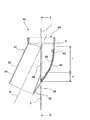
図1から図10は、本考案の第1の実施の形態に係る配管路の開閉バルブ2について説明するために参照する図である。
Hereinafter, the best mode for carrying out an on-off valve for a pipeline according to the present invention will be specifically described with reference to the drawings.
FIG. 1 to FIG. 10 are views which are referred to in order to describe the open /
本実施の形態に係る配管路の開閉バルブ2は、図1及び図2に示すように、本体部4と回転体6とを備えて構成されている。開閉バルブ2の本体部4は、円筒形状のハウジング8と、このハウジング8に接合し連通する円筒形状の下流側配管路10と、閉止壁12とを備えて構成されている。
As shown in FIGS. 1 and 2, the open /
また、開閉バルブ2の回転体6は、図3に示すように、鉛直方向に伸びる軸線Lを有する鉛直管18と、円筒形状の一部を用いて形成された半割り管20とを有する回転弁14と、上記ハウジング8に嵌合する嵌合部16とを備えて構成されている。開閉バルブ2は、この回転体6の回転弁14の上端部が、不図示の同一軸線の上流側配管路の下流側端部に対向して配設され、この不図示の上流側配管路から供給される粉体物がその中を軸線方向の下流側に流れるようになっている。
Further, as shown in FIG. 3, the
回転体6は、その嵌合部16が、高さが低い円筒形状に形成され、この嵌合部16の半径方向内側に回転弁14の鉛直管18が同一軸線上に配置されている。この回転体6の鉛直管18と嵌合部16とは、その上端部同士が上側平面部17を介して繋がって一体的に形成されている。
The rotating
回転体6は、その回転弁14における鉛直管18の外周と嵌合部16の内周との間に、本体部4におけるハウジング8の上端部を入り込ませるようにして、このハウジング8の上端部と回転可能に嵌合している。また、回転体6の嵌合部16の外周面上には、不図示の歯車の歯が設けられている。この嵌合部16の不図示の歯車の歯は、不図示の他の駆動歯車の歯と噛み合っていることにより、回転体6は、ハウジング8の軸線Lを回転中心として回転駆動されるようになっている。
The rotating
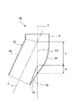
図4は、開閉バルブ2の本体部4の上面図であり、図5は、図4に示す本体部4のB−B線矢視の断面図である。
FIG. 4 is a top view of the
本体部4の下流側配管路10は、図5に示すように、ハウジング8の直径と同じ大きさの直径を有する円筒管により形成されている。この下流側配管路10は、その軸線bが、ハウジング8の軸線Lと、この軸線L上の点Xで交差するように配置されている。
As shown in FIG. 5, the
また、下流側配管路10は、その軸線bが伸びる方向におけるハウジング8側の端部において、その円筒形状の側壁のうちの半円周部分の縁が、図4及び図5に示すように、ハウジング8の半円周部分の側壁に接合されている。
Moreover, as shown in FIG.4 and FIG.5, as for the
すなわち、図5に示すように、下流側配管路10は、その円筒形状の側壁のうち、図5中における軸線bよりも左上側の範囲の半円周部分の側壁のハウジング8側の縁が、ハウジング8の側壁に接合されている。
That is, as shown in FIG. 5, the
また、下流側配管路10は、その軸線bの図5中右下側の半円周部分の側壁が、ハウジング8の軸線Lと下流側配管路10の軸線bの双方を含む第1平面(図 中、符号 参照)に直交すると共にハウジング8の軸線Lを含む第2平面(図5中、軸線Lを含んで紙面と垂直の方向に広がる平面)内において、閉止壁12と接合するようになっている。
Further, the
すなわち、下流側配管路10は、図6に示すように、この図6の紙面と平行方向に広がる仮想平面F内に含まれ、おおむね縦長の楕円環形状のうちの下側半分の形状に形成される接合面10aが、図1及び図5に示すように、閉止壁12と接合するようになっている。
That is, as shown in FIG. 6, the
また、下流側配管路10には、図5,6に示すように、その接合面10aの下端部と、ハウジング8の軸線Lとが交差する位置に、後述するピン90(図3,9参照)が嵌合するためのピン用孔80が形成されている。
Further, as shown in FIGS. 5 and 6, the
図6に示すように、このピン用孔80は、その軸線が、ハウジング8の軸線Lと同一線上にあって、本体部4のハウジング8側に開口するように形成されている。下流側配管路10は、図5に示すように、このピン用孔80の内周を囲む、下流側配管路10と一体の肉厚部分の分だけが、その接合面10aよりも閉止壁12側に入り込んで形成され、閉止壁12はその部分を避けて形成されている。
As shown in FIG. 6, the
次に、本体部4の閉止壁12は、図6に示す下流側配管路10の接合面10aと接合するため、その接合面10aと同じ形状の接合面を有している。そして、閉止壁12は、図5に示すように、その全体の立体形状が、下流側配管路10の接合面10aと同じ形状の接合面12aの平面形状をハウジング8の軸線Lを中心として回転させることにより形成される回転体のうち、下流側配管路10の接合面10aとの接合面12aから下流側配管路10とは反対側のみに形成される形状部分として形成されている。
Next, the closing
また、閉止壁12は、ハウジング8の軸線Lが伸びる方向(図5中、上下方向)における、そのハウジング8側の端部の水平面がハウジング8の閉止壁12側半分の水平下端面に接合されている。
Further, in the direction in which the axis L of the
図7は、開閉バルブ2の回転体6の側面断面図である。また、図8は、図7に示す回転体6のD−D線矢視の正面図である。回転体6の回転弁14は、図7及び図8に示すように、上下方向に開口し鉛直方向に伸びる鉛直管18と、この鉛直管18と一体的に形成され、鉛直管18の下側に傾斜して配置される半割り管20を備えて構成されている。
FIG. 7 is a side sectional view of the
回転体6における回転弁14の鉛直管18は、図3に示すように本体部4のハウジング8に嵌合したときのハウジング8の軸線Lと同じ軸線Lを共有しているので、回転体6の鉛直管18は半割り管20と共に、その軸線Lの周りに回転するようになっている。
Since the
また、回転弁14の半割り管20は、図7に示すように、傾斜して配置される不図示の仮想円筒体の一部分により構成されるような形状に形成されている。ここで、この不図示の仮想円筒体は、鉛直管18の下部に接合し、その軸線bが、図3に示すように、本体部4における下流側配管路10の軸線bと一致するように想定されるものである。
Further, as shown in FIG. 7, the
回転弁14の半割り管20は、図7に示すように、おおむね、このような不図示の仮想円筒体を、その軸線bの図7中右下側の半円周部分の側壁が、図7に示す、ハウジング8の軸線Lと下流側配管路10の軸線bの双方を含む仮想平面M(図7の紙面と一致する第1平面)に直交すると共に、ハウジング8の軸線Lを含む仮想平面F(図7の紙面に直交する第2平面)と平行で、かつ、この仮想平面Fから後述する掻取り部24の幅の半分の長さ分だけ図7中左側に離れて配置される仮想切断面Sで切断し、このような仮想切断面Sより図7中左側の部分を取り去ったような形状に形成されている。
As shown in FIG. 7, the
ここで、図7中において、仮想切断面Sを示す二点鎖線は、図面の複雑化を防止するため、回転体6の掻取り部24の幅の図中左側の形状を示す実線と重なり合う範囲内においては、図示しないようにしている。
Here, in FIG. 7, the two-dot chain line indicating the virtual cut surface S overlaps the solid line indicating the shape on the left side of the width of the scraping
これにより、回転弁14の半割り管20は、図8に示すように、この図8の紙面に平行の仮想切断面Sで不図示の仮想円筒体を切断することにより形成される切り口の面と一致する掻取り部24の面が、おおむね、縦長の楕円環形状のうちの下側半分の部分の形状に形成され、このような掻取り部24に囲まれたその内側空間が、接続口22を構成するようになっている。この半割り管20の接続口22は、その形状が、図6に示す下流側配管路10の接合面10aの形状よりわずかに小さな略相似形になっている。
Thereby, as shown in FIG. 8, the
また、回転弁14には、図7及び図8に示すように、その半割り管20の接続口22の外周に沿うように、帯状の掻取り部24が形成されている。この掻取り部24は、図7中、左右方向に一定幅を有するように形成されている。
Moreover, as shown in FIG.7 and FIG.8, the strip | belt-shaped
また、回転弁14の鉛直管18には、図7及び図8に示すように、その円周方向の外周面上を1周する帯状の仕切り部26が形成されている。回転弁14の掻取り部24は、その長さ方向(半割り管20の接続口22の周方向に沿う方向)の両端部が仕切り部26にT字状に接続するように形成されており、これら掻取り部24と仕切り部26は、回転弁14と一体的に形成されている。
Further, as shown in FIGS. 7 and 8, the
また、回転弁14には、その掻取り部24における長さ方向(半割り管20の接続口22の周方向に沿う方向)中央の最下端部位置であって、図5及び図6に示す本体部4の下流側配管路10のピン用孔80に対応する位置に、図3に示すピン90が回転可能に嵌合するためのピン用孔82が形成されている。
The
開閉バルブ2は、その回転体6の回転弁14が、図3に示すような本体部4の下流側配管路10に連通させた状態から、ハウジング8の軸線Lを中心として90度回転した図9に示すような状態を経由した後、さらに90度回転した状態(図3に示す状態から180度回転した状態)で、回転弁14が、この半割り管20と閉止壁12とで囲まれる内部空間と、下流側配管路10の(閉止壁12と反対側の)内部空間とを遮断するようになっている。
The on-off
なお、図7及び図8に示す回転弁14の掻取り部24の半割り管20からの高さ、及び仕切り部26の鉛直管18からの高さのそれぞれは、この掻取り部24及び仕切り部26のそれぞれと、閉止壁12及びハウジング8との間の互いの対向方向の隙間(図9中、寸法c1参照)が、0.1mm程度になるように設定されているので、掻取り部24が下流側配管路10等の内側に付着しようとしている粉体物を掻取るようになっている。
The height of the
このような本実施の形態に係る配管路の開閉バルブ2では、図3に示すように、その回転体6の回転弁14の半割り管20が、本体部4の下流側配管路10に連通した状態において、半割り管20が配管路の一部を構成すようになるので、その半割り管20が配管路内を粉体物が円滑に通るようにすることができる。
In the open /
そして、バタフライ弁を用いた従来の配管路の開閉バルブのように、そのバタフライ弁が閉じる動作の際に、バタフライ弁の周部と配管路内壁との間や、バタフライ弁の周部とその回動停止部の内壁との間に粉体物が挟み込まれることにより、バタフライ弁が完全に閉じることを阻害されるようなことはないので、開閉バルブ2の回転弁14の動作が阻害されることを防止することができる。
When the butterfly valve closes like a conventional pipe line opening / closing valve using a butterfly valve, the butterfly valve and the inner wall of the butterfly valve, and the butterfly valve circumference and its circuit Since the powdered material is sandwiched between the inner wall of the movement stop portion and the butterfly valve is not inhibited from being completely closed, the operation of the
このため、本実施の形態に係る配管路の開閉バルブ2によれば、回転弁14の回転動作が阻害されることを防止することができると共に、配管路内を流れる粉体物の均一性が劣化したり、粉体物が配管路外に漏れ出すことを防止することができる。
For this reason, according to the on-off
また、本実施の形態に係る開閉バルブ2によれば、バタフライ弁を用いた従来の配管路の開閉バルブと異なって、バタフライ弁自体の板厚部が配管路内に残ることがないため、それが邪魔となって配管路内を流れる粉体物が均一に流れるのを阻害するのを防止することができる。
In addition, according to the on-off
また、粉体物が配管路内にあるバタフライ弁と擦れることにより粉体物が本来の粒径より細かく粉砕されたり、逆にバタフライ弁に押し付けられて互いに付着し合って、本来の粒径より大きな塊状となったりすることを防止することができる。 In addition, the powdered material is crushed finer than the original particle size by rubbing with the butterfly valve in the piping, or conversely, it is pressed against the butterfly valve and adheres to each other. A large lump can be prevented.
また、回転体6の回転弁14の開閉動作が、前記バタフライ弁のように、その上流側の粉体物を押し戻すように作用することがないので、粉体物を押し潰して更に細かく粉砕してしまったり、逆に押し固めてしまったりすることを防止することができる。
Further, unlike the butterfly valve, the opening / closing operation of the
また、本実施の形態に係る開閉バルブ2によれば、スライドゲート弁を用いた従来の配管路の開閉バルブと異なって、その回転体6の回転弁14を外側に引き出す必要がないので、スリットなどの開口部を形成する必要も無いため、配管路内から開口部を通って粉体物が外部に漏れ出ることを防止することができる。
Also, according to the on-off
次に、図11は、本考案の第2の実施の形態に係る配管路の開閉バルブ30について説明するために参照する図である。前記第1の実施の形態に係る配管路の開閉バルブ2と同様の部分には同じ符号を用いて説明し、同様の構成についての重複する説明は省略するものとする。
Next, FIG. 11 is a figure referred in order to demonstrate the opening / closing
本実施の形態に係る配管路の開閉バルブ30は、図11に示すように、前記第1の実施の形態に係る開閉バルブ2の回転体6の代わりに、回転体32を備えている。この回転体32は、前記第1の実施の形態に係る開閉バルブ2の回転体6における回転弁14の代わりに、回転弁34を備えている。
As shown in FIG. 11, the opening / closing
この回転体32の回転弁34は、垂直管36と半割り管38を備えている。この回転弁34の垂直管36は、前記第1の実施の形態に係る開閉バルブ2における回転弁14の鉛直管18と同様に、上下方向に開口し鉛直方向に伸びる円筒状に形成されている。
The
また、回転弁34の半割り管38は、その接続口39の平面形状が、前記第1の実施の形態に係る開閉バルブ2における回転弁14の半割り管20の接続口22(図8参照)の平面形状と同じ形状に形成されている。
Further, the
一方、回転弁34の半割り管38は、図11に示すように、その立体形状が、おおむね、その接続口39の平面形状をハウジング8の軸線Lを中心として回転させることにより形成される回転体の形状のうち、図7に示す仮想切断面Sと同じ仮想切断面Sで切断し、この仮想切断面Sより図7中左側の部分を取り去ったような形状に形成されている。
On the other hand, as shown in FIG. 11, the
また、回転弁34の接続口39の外周上には、前記第1の実施の形態に係る回転弁14の掻取り部24と同様の掻取り部24が形成されており、垂直管36の外周上には、前記第1の実施の形態に係る及び仕切り部26と同様の仕切り部26が形成されている。
Further, a scraping
これにより、回転弁34の半割り管38の外周面と、本体部4の閉止壁12の内周面との間の対向方向の隙間の大きさは、この回転弁34における軸線Lを中心とする水平周方向に沿って見ていくと、この回転弁34における水平周方向の両端部(掻取り部24の部分)では、前記第1の実施の形態に係る回転弁14と同じ0.1mm程度に設定されている(図9中、寸法c1参照)。
Thereby, the size of the gap in the facing direction between the outer peripheral surface of the
また、図11に示すように、回転弁34の半割り管38の外周面における、水平周方向の両端部の間の中間部分では、回転弁34の半割り管38の外周面と、本体部4の閉止壁12の内周面との間の対向方向の隙間の大きさ(図11中、寸法c2)は、経験則に基づき、この開閉バルブ30内を通る粉体物の粒径の4倍程度の長さに設定されている。
Further, as shown in FIG. 11, the outer peripheral surface of the
このような本実施の形態に係る配管路の開閉バルブ30によれば、前記第1の実施の形態と同様に、回転弁34の回転動作が阻害されることを防止することができると共に、配管路内を流れる粉体物の均一性が劣化したり、粉体物が配管路外に漏れ出すことを防止することができる。
According to the pipe opening / closing
また、本実施の形態に係る配管路の開閉バルブ30によれば、その回転体32の半割り管38と、本体部4の閉止壁12との間に一定の隙間以上の空間が形成されないようになっているので、それらの半割り管38と閉止壁12との間に粉体物が滞留しないようにすることができる。
In addition, according to the opening / closing
次に、図12から図14は、本考案の第3の実施の形態に係る配管路の開閉バルブ40について説明するために参照する図である。
本実施の形態に係る開閉バルブ40は、図12に示すように、前記第2の実施の形態に係る配管路の開閉バルブ30における、本体部4及び回転体32のそれぞれの代わりに、類似の本体部42及び回転体44を備えている。
Next, FIGS. 12 to 14 are views which are referred to for explaining the open /
As shown in FIG. 12, the opening / closing
開閉バルブ40における本体部42は、前記第2の実施の形態に係る本体部4の閉止壁12と異なる閉止壁46を備えている。また、回転体44は、回転弁48を備えており、この回転弁48は、前記第2の実施の形態に係る半割り管38と異なる半割り管50を備えている。
The
本体部42の閉止壁46、及び回転体44における回転弁48の半割り管50のそれぞれは、ハウジング8の軸線Lが伸びる方向における、図12中の寸法mの範囲内の形状が、前記第2の実施の形態に係る閉止壁12(図11参照)、及び半割り管38のそれぞれにおける相当部分の立体形状が、逆中空円錐形状に置き換えられて形成されている。
Each of the closing
また、図12に示すように、閉止壁46及び半割り管50のそれぞれは、図12中の寸法nの範囲内において、前記第2の実施の形態に係る閉止壁12及び半割り管38の相当部分の形状と同一形状に形成されている。設計段階において閉止壁46及び半割り管50のそれぞれの形状を定める際には、図12中の寸法mで示す範囲と、寸法nで示す範囲の境界は、任意に設定することができる。
Further, as shown in FIG. 12, each of the closing
また、開閉バルブ40における本体部42は、図12及び図13に示すように、前記第2の実施の形態に係る開閉バルブ30における本体部4の下流側配管路10と異なる下流側配管路52を備えている。
Further, as shown in FIGS. 12 and 13, the
この下流側配管路52は、円筒部54と、この円筒部54の軸線bに直角の断面形状を拡張する拡張部56を備えて構成されている。拡張部56は、図13に示すように、2枚の対称形状の三角板58同士を接合して形成され、図12に示すように、閉止壁46における図12中の寸法mの範囲の中空部分の開口部に対向して接合されるように配設されている。
The
これにより、下流側配管路52は、図14に示すように、その円筒部54と拡張部56のそれぞれの閉止壁46側の端面を接合して形成され閉止壁46に接合する接合面52aが、図13に示すように、閉止壁46の接合面の平面形状に対応する形状に形成されている。
As a result, as shown in FIG. 14, the downstream side piping 52 has a joining
このような本実施の形態に係る開閉バルブ40によれば、前記第1及び第2の実施の形態と同様に、回転弁48の回転動作が阻害されることを防止することができると共に、配管路内を流れる粉体物の均一性が劣化したり、粉体物が配管路外に漏れ出すことを防止することができる。
According to the on-off
また、本実施の形態に係る配管路の開閉バルブ40によれば、前記第2の実施の形態と同様に、その回転体44の半割り管50と、本体部42の閉止壁46との間に一定の隙間以上の空間が形成されないようになっているので、それらの半割り管50と閉止壁46との間に粉体物が滞留しないようにすることができる。
Further, according to the pipe opening / closing
また、本実施の形態に係る配管路の開閉バルブ40によれば、その回転体44の半割り管50が、本体部42のハウジング8と反対側の端部において、その傾斜を下流側配管路52の軸線bに近づけるように形成されているので、配管路内を流れる粉体物の速度を落とさないようにすることができる。
In addition, according to the pipe opening and closing
なお、前記第1から第3の実施の形態に係る配管路の開閉バルブ2,30,40においては、粉体物を通すようになっていたが、粉体物以外のものを通すようになっていてもよい。例えば、液体や気体等の流体物、又は豆や顆粒状の薬等の粒状体を通すようになっていてもよい。
In the pipe opening and
また、前記第1から第3の実施の形態に係る配管路の開閉バルブ2,30,40においては、その回転弁14,34,48に、掻取り部24及び仕切り部26を一体的に形成するようになっていたが、別個に形成して取り付けるようになっていてもよい。また、掻取り部24及び/又は仕切り部26は、設けないようになっていてもよい。
Further, in the open /
2 開閉バルブ
4 本体部
6 回転体
8 ハウジング
10 下流側配管路
10a 接合面
12 閉止壁
12a 接合面
14 回転弁
16 嵌合部
17 上側平面部
18 鉛直管
20 半割り管
22 接続口
24 掻取り部
26 仕切り部
30 配管路の開閉バルブ
32 回転体
34 回転弁
36 鉛直管
38 半割り管
39 接続口
40 開閉バルブ
42 本体部
44 回転体
46 閉止壁
48 回転弁
50 半割り管
52 下流側配管路
52a 接合面
54 円筒部
56 拡張部
58 三角板
80,82 ピン用孔
90 ピン
DESCRIPTION OF
Claims (3)
前記ハウジングとほぼ同一径を有する略円筒形状に形成され、その軸線が前記ハウジングの軸線と交差するようにこのハウジングに接合する下流側配管路と、
前記ハウジングと前記下流側配管路との接合部の内部に前記ハウジングの軸線を中心として回転可能に設けられ、円筒形状の一部を用いて形成された回転弁とを備え、
前記回転弁が前記ハウジングの軸線を中心として回転することにより、前記円筒形状の一部が前記ハウジングと前記下流側配管路との間を連通したり遮断したりすることができるようにした
ことを特徴とする配管路の開閉バルブ。 A cylindrical housing disposed on the same axis as the cylindrical upstream pipe line;
A downstream pipe line formed in a substantially cylindrical shape having substantially the same diameter as the housing and joined to the housing so that its axis intersects the axis of the housing;
A rotary valve provided inside a joint portion between the housing and the downstream pipe line so as to be rotatable about the axis of the housing, and formed using a part of a cylindrical shape,
The rotating valve rotates about the axis of the housing, so that a part of the cylindrical shape can communicate or block between the housing and the downstream piping. An open / close valve for the pipeline.
Priority Applications (1)
| Application Number | Priority Date | Filing Date | Title |
|---|---|---|---|
| JP2008001512U JP3141987U (en) | 2008-03-14 | 2008-03-14 | Open / close valve for piping |
Applications Claiming Priority (1)
| Application Number | Priority Date | Filing Date | Title |
|---|---|---|---|
| JP2008001512U JP3141987U (en) | 2008-03-14 | 2008-03-14 | Open / close valve for piping |
Publications (1)
| Publication Number | Publication Date |
|---|---|
| JP3141987U true JP3141987U (en) | 2008-05-29 |
Family
ID=43292023
Family Applications (1)
| Application Number | Title | Priority Date | Filing Date |
|---|---|---|---|
| JP2008001512U Expired - Fee Related JP3141987U (en) | 2008-03-14 | 2008-03-14 | Open / close valve for piping |
Country Status (1)
| Country | Link |
|---|---|
| JP (1) | JP3141987U (en) |
-
2008
- 2008-03-14 JP JP2008001512U patent/JP3141987U/en not_active Expired - Fee Related
Similar Documents
| Publication | Publication Date | Title |
|---|---|---|
| JP5767777B2 (en) | Valve structure | |
| CN103562606B (en) | There is the valve of dual rotation valve member | |
| EP1828650B1 (en) | Rotary valve for industrial fluid flow control | |
| CN111720591B (en) | Distributor valves and refrigeration systems | |
| CN204328077U (en) | A kind of V-type three-way regulating ball valve | |
| US20100243938A1 (en) | Fluid passage valve and method of assembling same | |
| JP5408925B2 (en) | Channel switching device | |
| WO2014024503A1 (en) | Rotary valve seal member and rotary valve using same | |
| CN103836216B (en) | Board-like two-way self-pressed sealed valve | |
| CN114321426B (en) | Plug valve and water air conditioner | |
| JP3141987U (en) | Open / close valve for piping | |
| JP6122665B2 (en) | Channel switching device | |
| CN102971558A (en) | Fluid valve | |
| US7900653B2 (en) | Two-way ball valve to prevent backwash | |
| JP6508804B2 (en) | Double eccentric type butterfly valve | |
| JP5356421B2 (en) | Valve device | |
| JP2010223333A (en) | Butterfly valve device | |
| KR100702209B1 (en) | Double Blade Valve | |
| CN217482013U (en) | Plug valve and water air conditioner | |
| JP2021143743A (en) | Rotary valve | |
| JP7093201B2 (en) | Flow path switching valve | |
| JP2021055705A (en) | Seal structure of rotary valve | |
| JP4086495B2 (en) | Butterfly valve with constant flow rate filling function | |
| KR102609877B1 (en) | Ball for valve and ball valve with the same | |
| KR101507970B1 (en) | Butterfly valve |
Legal Events
| Date | Code | Title | Description |
|---|---|---|---|
| R150 | Certificate of patent or registration of utility model |
Free format text: JAPANESE INTERMEDIATE CODE: R150 |
|
| FPAY | Renewal fee payment (event date is renewal date of database) |
Free format text: PAYMENT UNTIL: 20110507 Year of fee payment: 3 |
|
| LAPS | Cancellation because of no payment of annual fees |