JP3142013U - Automatic fastening device - Google Patents
Automatic fastening device Download PDFInfo
- Publication number
- JP3142013U JP3142013U JP2008001557U JP2008001557U JP3142013U JP 3142013 U JP3142013 U JP 3142013U JP 2008001557 U JP2008001557 U JP 2008001557U JP 2008001557 U JP2008001557 U JP 2008001557U JP 3142013 U JP3142013 U JP 3142013U
- Authority
- JP
- Japan
- Prior art keywords
- screw
- fastening
- fastening member
- machine
- holder
- Prior art date
- Legal status (The legal status is an assumption and is not a legal conclusion. Google has not performed a legal analysis and makes no representation as to the accuracy of the status listed.)
- Expired - Lifetime
Links
Images




Landscapes
- Dovetailed Work, And Nailing Machines And Stapling Machines For Wood (AREA)
Abstract
【課題】締結部材を平面的に高密度に用いて被締結部材を締結することができる自動締結装置を提供する。
【解決手段】締結部材供給機13と締結機14との間で搬送機によって締結部材保持具23を搬送するので、一つの締結部材に対して締結部材供給機13と締結機14とを夫々別個に配置すればよく、一つの締結部材に対して締結部材供給機13と締結機14との両方を夫々平面的に高密度に配置することができる。しかも、締結部材保持具23における複数の締結部材保持部24の各々が締結部材を平面状の整列状態で弾性的に保持するので、締結部材保持具23の機構が簡単でよく、締結部材保持具23が締結部材を平面的に高密度に保持することができる。
【選択図】図1An automatic fastening device capable of fastening a member to be fastened using the fastening members at a high density in a plane is provided.
Since the fastening member holder 23 is transported by a transporter between the fastening member supply machine 13 and the fastening machine 14, the fastening member supply machine 13 and the fastening machine 14 are separately provided for one fastening member. The fastening member feeder 13 and the fastening machine 14 can both be arranged in a high density in a plane with respect to one fastening member. In addition, since each of the plurality of fastening member holding portions 24 in the fastening member holder 23 elastically holds the fastening member in a planar alignment state, the mechanism of the fastening member holder 23 may be simple, and the fastening member holder 23 can hold the fastening member at a high density in a plane.
[Selection] Figure 1
Description
本考案は、締結部材を用いて被締結部材を自動的に締結するための自動締結装置に関するものである。 The present invention relates to an automatic fastening device for automatically fastening a fastening member using a fastening member.
自動締結装置の一種として、特許文献1〜4に記載されている様に、ねじを供給する工程とこの供給されたねじを被締結部材へ螺入する工程とを自動的に且つ連続的に行う自動ねじ締め機がある。
特許文献1〜3の自動ねじ締め機ではねじ締め機の下方へねじを直接に供給し、特許文献4の自動ねじ締め機ではねじを供給された割型開閉式のねじチャックがねじの姿勢を保持しつつねじ締め機の下方へねじを搬送する。しかし、特許文献1〜3の自動ねじ締め機では、一つのねじに対してねじ供給機とねじ締め機との両方を同時に配置する必要があるので、ねじを平面的に高密度で螺入することができない。また、特許文献4の自動ねじ締め機では、ねじ自体に比べてねじチャックに大きな面積が必要であるので、やはりねじを平面的に高密度で螺入することができない。従って、本考案は、締結部材を平面的に高密度に用いて被締結部材を締結することができる自動締結装置を提供することを目的としている。 In the automatic screw tightening machines of Patent Documents 1 to 3, the screw is directly supplied to the lower side of the screw tightening machine. The screw is conveyed to the lower side of the screw tightening machine while being held. However, in the automatic screw tightening machines disclosed in Patent Documents 1 to 3, since it is necessary to simultaneously arrange both the screw supply machine and the screw tightening machine with respect to one screw, the screws are screwed in at a high density in a plane. I can't. Further, in the automatic screw tightening machine of Patent Document 4, since the screw chuck requires a larger area than the screw itself, the screw cannot be screwed in at a high density in a plane. Accordingly, an object of the present invention is to provide an automatic fastening device that can fasten a fastened member by using fastening members in a high density in a plane.
請求項1に係る自動締結装置では、締結部材供給機と締結機との間で搬送機によって締結部材保持具を搬送するので、一つの締結部材に対して締結部材供給機と締結機とを夫々別個に配置すればよく、一つの締結部材に対して締結部材供給機と締結機との両方を夫々平面的に高密度に配置することができる。しかも、締結部材保持具における複数の締結部材保持部の各々が締結部材を平面状の整列状態で弾性的に保持するので、締結部材保持具の機構が簡単でよく、締結部材保持具が締結部材を平面的に高密度に保持することができる。 In the automatic fastening device according to claim 1, the fastening member holder is transported by the transporter between the fastening member supply machine and the fastening machine, so that the fastening member feeder and the fastening machine are respectively connected to one fastening member. What is necessary is just to arrange | position separately, and it can arrange | position both a fastening member supply machine and a fastening machine with respect to one fastening member at high density in a plane, respectively. In addition, since each of the plurality of fastening member holding portions in the fastening member holder elastically holds the fastening member in a planar alignment state, the mechanism of the fastening member holder can be simple, and the fastening member holder is the fastening member. Can be held at a high density in a plane.
請求項2に係る自動締結装置では、締結機としてねじ締め機または圧入機の何れをも用いることができるので、被締結部材に対してねじの螺入とくぎの圧入との何れをも行うことができる。
In the automatic fastening device according to
請求項1に係る自動締結装置では、一つの締結部材に対して締結部材供給機と締結機との両方を夫々平面的に高密度に配置することができ、しかも、締結部材保持具が締結部材を平面的に高密度に保持することができるので、締結部材を平面的に高密度に用いて被締結部材を締結することができる。 In the automatic fastening device according to claim 1, both the fastening member feeder and the fastening machine can be arranged in a high density in a plane with respect to one fastening member, and the fastening member holder is a fastening member. Can be held at a high density in a plane, so that the fastening member can be fastened using the fastening members at a high density in a plane.
請求項2に係る自動締結装置では、被締結部材に対してねじの螺入とくぎの圧入との何れをも行うことができるので、ねじとくぎとの何れをも平面的に高密度に用いて被締結部材を締結することができる。
In the automatic fastening device according to
以下、本考案の第一〜第三実施形態を、図1〜10を参照しながら説明する。図1〜6が、本考案の第一実施形態である自動ねじ締め装置を示している。図1に示されている様に、この自動ねじ締め装置11では、ベルトコンベア12の上流側の上方及び下流側の上方にねじ供給機13及びねじ締め機14が夫々配置されている。ねじ供給機13には板状のねじ供給具15が備えられており、このねじ供給具15には一対の案内ピン16が備えられている。ねじ供給具15には筒状の複数のねじ供給部17が平面状の整列状態で備えられており、各々のねじ供給部17と圧縮空気式のねじ供給本体21とがねじ供給パイプ22で互いに接続されている。
Hereinafter, first to third embodiments of the present invention will be described with reference to FIGS. 1-6 has shown the automatic screw fastening apparatus which is 1st embodiment of this invention. As shown in FIG. 1, in the automatic
自動ねじ締め装置11には板状のねじ保持具23が備えられており、このねじ保持具23に筒状の複数のねじ保持部24がねじ供給具15のねじ供給部17に対応する整列状態で備えられている。図2に示されている様に、各々のねじ保持部24の外周面には所定の角度間隔、例えば90°間隔で軸方向に切れ込み25が設けられており、切れ込み25同士の間の部分がねじ保持部24の半径方向へ弾性を有している。各々のねじ保持部24の内径は、ねじ供給機13から供給されるねじのねじ頭の外径よりも僅かに小さい。ねじ保持具23には、ねじ供給具15の案内ピン16が挿入される一対の案内孔26と、一対の案内ピン27とが備えられている。
The automatic
ねじ締め機14には板状のねじ回し保持具31が備えられており、このねじ回し保持具31に複数の電動ねじ回し32がねじ供給具15のねじ供給部17に対応する整列状態で備えられている。各々の電動ねじ回し32ではねじ回し33とモータ34とが互いに同軸状であり、各々のねじ回し33の長さは互いに等しい。各々のねじ回し33の周囲とねじ回し保持具31との間には緩衝用のコイルばね35が配置されている。また、ねじ回し保持具31には、ねじ保持具23の案内孔26に挿入される一対の案内ピン36が備えられている。
The
被ねじ締め部材37はパレット41上に位置決めされた状態でベルトコンベア12上を搬送され、このパレット41にはねじ保持具23の案内ピン27が挿入される一対の案内孔42が備えられている。また、ベルトコンベア12には、ねじ供給機13の下方とねじ締め機14の下方とでパレット41を正確な位置に停止させることのできるストッパ43が備えられている。
The member to be screwed 37 is conveyed on the
以上の様な自動ねじ締め装置11によるねじの螺入に際しては、図3(a)に示されている様に、ねじ供給機13のねじ供給具15が下降し、ねじ供給具15の案内ピン16がねじ保持具23の案内孔26に挿入して、ねじ供給具15がねじ保持具23と合体する。そして、この合体状態で、ねじ供給本体21からねじ供給パイプ22及びねじ供給部17を介して、ねじ保持具23のねじ保持部24へ、ねじ44(図2)が供給される。上述の様にねじ保持部24の内径がねじ44のねじ頭の外径よりも僅かに小さく且つねじ保持部24の切れ込み25同士の間の部分がねじ保持部24の半径方向へ弾性を有しているので、ねじ保持部24へ供給されたねじ44はねじ保持部24から落下することなくこのねじ保持部24内に保持される。
When the screw is screwed by the automatic
ねじ保持具23のねじ保持部24へねじ44が供給されると、ねじ供給具15が上昇してねじ保持具23から離隔すると共に、図示されていない搬送機によって、図3(b)に示されている様に、ねじ保持具23が下降し、ねじ保持具23の案内ピン27がベルトコンベア12上のパレット41の案内孔42に挿入して、ねじ保持具23がパレット41と合体する。この合体が完了すると、ねじ供給機13の下方のストッパ43が解除され、図3(c)に示されている様に、合体状態のねじ保持具23及びパレット41がねじ締め機14の下方のストッパ43に当接する位置までベルトコンベア12によって搬送される。
When the
合体状態のねじ保持具23及びパレット41がねじ締め機14の下方まで搬送されると、図4に示されている様に、ねじ締め機14が下降する。そして、各々の電動ねじ回し32が、ねじ保持具23のねじ保持部24内に保持されている対応するねじ44を被ねじ締め部材37内へ螺入する。上述の様に、ねじ保持部24の内径がねじ44のねじ頭の外径よりも僅かに小さいが、ねじ保持部24の切れ込み25同士の間の部分がねじ保持部24の半径方向へ弾性を有しているので、ねじ回し33がねじ保持部24の軸方向への圧力をねじ44に印加すると、ねじ保持部24の切れ込み25同士の間の部分がねじ保持部24の半径方向へ押し広げられて、ねじ44がねじ保持部24から脱出する。
When the
ねじ44が被ねじ締め部材37内へ螺入されると、ねじ締め機14が図3(c)に示されている元の位置まで上昇し、図示されていない搬送機によってねじ保持具23がねじ締め機14の下方で且つねじ44が螺入された被ねじ締め部材37の上方へ上昇する。そして、図示されていない搬送機によってこのねじ保持具23が図3(a)に示されている元の位置まで戻され、ねじ締め機14の下方のストッパ43が解除されて、ねじ44が螺入された被ねじ締め部材37がパレット41と共にベルトコンベア12によって搬送される。以上によって自動ねじ締め装置11によるねじの螺入の一周期が完了し、この周期が繰り返される。
When the
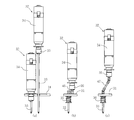
なお、以上の自動ねじ締め装置11では、図1に示されている様に、各々の電動ねじ回し32におけるねじ回し33とモータ34とが互いに同軸状であり且つ各々のねじ回し33の長さが互いに等しい。しかし、図5(a)に示されている様に、互いに隣接する一対の電動ねじ回し32のうちの一方の電動ねじ回し32のねじ回し33の長さを他方の電動ねじ回し32のねじ回し33とモータ34との合計の長さ以上にしてもよい。図5(a)の場合には、隣接するモータ34同士に阻害されることなくねじ回し33同士の間隔を図1の場合よりも狭くすることができて、ねじ44を図1の場合よりも平面的に高密度で螺入することができる。
In the above automatic
また、図5(b)に示されている様に、ねじ回し33とモータ34との互いの軸芯をずらせて、ねじ回し33とモータ34とをベルト45で機械的に結合してもよく、図5(c)に示されている様に、ねじ回し33とモータ34との互いの軸芯をずらせて、ねじ回し33とモータ34とを自在継手46で機械的に結合してもよい。図5(b)(c)の場合にも、隣接するモータ34同士に阻害されることなくねじ回し33同士の間隔を図1の場合よりも狭くすることができて、ねじ44を図1の場合よりも平面的に高密度で螺入することができる。
Further, as shown in FIG. 5B, the
また、以上の自動ねじ締め装置11では、図1に示されている様に、ねじ保持具23の複数のねじ保持部24に対応する個数のねじ供給部17を有するねじ供給具15をねじ供給機13が備えており、同様にねじ保持具23の複数のねじ保持部24に対応する個数の電動ねじ回し32を有するねじ回し保持具31をねじ締め機14が備えている。しかし、図6(a)(b)に示されている様に、長手方向に長孔47が設けられているアーム48の一方の端部にねじ供給部17または電動ねじ回し32を取り付け、図6(c)に示されている様に、アーム48を回動させ且つその回動中心を長孔47に沿って移動させつつねじ44の供給や螺入を行ってもよい。図6の場合には、一つのねじ供給部17や電動ねじ回し32で複数個所におけるねじ44の螺入や圧入を行うことができるので、ねじ供給部17や電動ねじ回し32の個数を図1の場合よりも少なくすることができる。
Further, in the above automatic
図7が、本考案の第二実施形態である自動ねじ締め装置を示している。この自動ねじ締め装置51では、上述の自動ねじ締め装置11におけるねじ供給機13の代わりにねじ供給機52が用いられている。このねじ供給機52にもねじ供給具15が備えられていて、ねじ供給部17にねじ供給パイプ22の一端部が接続されている。しかし、これらのねじ供給パイプ22の各々の他端部は板状のねじ受け具53における筒状の複数のねじ受け部54の各々に接続されており、複数のねじ受け部54はねじ受け具53に直線状に整列されている。
FIG. 7 shows an automatic screw tightening device according to a second embodiment of the present invention. In the automatic
ねじ受け具53上には板状のねじ配給具55が配置されており、このねじ配給具55には複数のねじ受け部54の一部に対応する筒状の複数のねじ配給部56と複数のねじ受け部54に対応する筒状の複数のねじ送り部57とが備えられている。この自動ねじ締め装置51では、ねじ受け部54及びねじ送り部57の個数が6個であり、ねじ配給部56の個数が2個である。図7に示されているねじ配給具55の初期位置では、2個のねじ配給部56が夫々第一のねじ受け部54と第四のねじ受け部54とに対応している。
A plate-shaped
2個のねじ配給部56と2個のねじ供給本体61とがねじ供給パイプ62で互いに接続されており、6個のねじ送り部57に共通の1本の圧縮空気供給パイプ63が接続されている。ねじ配給具55には、複数のねじ受け部54の整列方向へ延びるボールねじ64を介してステッピングモータ65が接続されており、複数のねじ受け部54の整列方向とは垂直な方向が軸心方向である空圧シリンダ66も接続されている。ステッピングモータ65は直線状に整列されている複数のねじ受け部54の1個分ずつねじ配給具55をねじ受け具53に対して間欠移動させ、空圧シリンダ66は複数のねじ受け部54の整列方向とは垂直な方向へねじ配給具55をねじ受け具53に対して移動させる。
Two
以上の様な自動ねじ締め装置51によるねじの螺入に際しては、まず、図7に示されているねじ配給具55の初期位置で、ねじ供給本体61からねじ供給パイプ62及びねじ配給部56を介して、ねじ受け具53の第一及び第四のねじ受け部54へ、ねじが供給される。次に、ステッピングモータ65の作動によって複数のねじ受け部54の1個分だけねじ配給具55をねじ受け具53に対して移動させて、ねじ配給具55の2個のねじ配給部56を夫々第二のねじ受け部54と第五のねじ受け部54とに対応させる。この状態で、上述の様に、ねじ受け具53の第二及び第五のねじ受け部54へねじが供給される。
When screws are screwed by the automatic
更に、上述と同様にしてねじ受け具53の第三及び第六のねじ受け部54へねじが供給されると、第一〜第六の総てのねじ受け部54へねじが供給されたことになる。なお、第一〜第六のねじ受け部54へ供給されたねじは、これらのねじ受け部54に保持されたままである。第三及び第六のねじ受け部54へねじが供給された時点では、ねじ配給具55のねじ送り部57は、ねじ受け具53のねじ受け部54に対して空圧シリンダ66の軸心方向へ変位しているだけで、ボールねじ64の延在方向ではねじ受け具53のねじ受け部54に整列している。
Further, when the screws are supplied to the third and sixth
従って、次に、空圧シリンダ66の作動によって、ねじ配給具55のねじ送り部57をねじ受け具53のねじ受け部54に対応させる。この状態で、圧縮空気供給パイプ63及びねじ配給具55のねじ送り部57を介してねじ受け具53の第一〜第六の総てのねじ受け部54に圧縮空気を供給すると、これら第一〜第六のねじ受け部54に保持されているねじが、ねじ供給パイプ22及びねじ供給具15のねじ供給部17を介して、ねじ保持具23のねじ保持部24へ供給される。この後は、上述の自動ねじ締め装置11と同様にして被ねじ締め部材37に対するねじの螺入が行われる。
Therefore, next, the operation of the
図8〜10が、本考案の第三実施形態である自動釘打ち装置の部品を示している。この自動釘打ち装置では、上述の自動ねじ締め装置11におけるねじ供給機13、ねじ保持具23、及びねじ締め機14の代わりに、夫々図8〜10に示されている釘供給機71、釘保持具72、及び釘打ち機73が用いられている。図8(a)に示されている様に、釘供給機71には板状の釘供給具74が備えられている。この釘供給具74には筒状の複数の釘供給部75が平面状の整列状態で備えられており、図8(a)(b)に示されている様に各々の釘供給部75と釘供給本体76とが釘供給パイプ77で互いに接続されている。
FIGS. 8-10 has shown the components of the automatic nailing apparatus which is 3rd embodiment of this invention. In this automatic nailing device, instead of the
図9(a)に示されている様に、釘保持具72には筒状の複数の釘保持部81が釘供給具74の釘供給部75に対応する整列状態で備えられている。各々の釘保持部81の内径は、釘供給機71から供給される釘の釘頭の外径よりも僅かに小さい。釘供給部75や釘保持部81の整列状態は、例えば木製パレットに製造される被釘打ち部材82に圧入される釘83の整列状態に対応しているので、被釘打ち部材82における釘83の整列状態に依存して変動する。
As shown in FIG. 9A, the
釘保持部81は、図9(b)に示されている様に内部が一様な筒状でもよく、図9(c)に示されている様に外周面に所定の角度間隔、例えば90°間隔で軸方向に切れ込み84が設けられていてもよい。切れ込み84が設けられている釘保持部81では切れ込み84同士の間の部分が釘保持部81の半径方向へ弾性を有しているが、内部が一様な筒状の釘保持部81も釘保持部81の半径方向へある程度の弾性を有している。従って、釘保持部81へ供給された釘は釘保持部81から落下することなくこの釘保持部81に保持される。切れ込み84が設けられている釘保持部81には、この釘保持部81の軸芯へ向かう突出部85が切れ込み84同士の間の各部分に設けられている。
The
図10(a)に示されている様に、板状の釘打ち機73には図10(b)に示されている柱状の複数の釘打ち部86が釘供給具74の釘供給部75に対応する整列状態で備えられている。釘の圧入機である以上の様な自動釘打ち装置による釘の圧入に際しても、油圧機等で釘打ち機73を押圧する以外は、自動ねじ締め装置11によるねじ44の螺入と実質的に同様の工程が行われる。なお、図9(d)に示されている様に、内部が一様な筒状の釘保持部81が用いられると、釘83が釘保持部81によって位置規制されるので、釘83が曲がっても圧入することができる。また、図9(e)に示されている様に、切れ込み84及び突出部85が設けられている釘保持部81が用いられると、突出部85によって釘83が心出しされる。
As shown in FIG. 10A, the plate-shaped
なお、以上の第一〜第三実施形態では、ねじ供給部17、電動ねじ回し32、ねじ受け部54、ねじ送り部57、釘供給部75、釘打ち部86等の個数が6個であり、ねじ配給部56等の個数が2個である。しかし、これらの個数は、これらの値に限定される必然性はなく、他の値であってもよい。
In the first to third embodiments described above, the number of the
本考案は、自動ねじ締め装置や自動釘打ち装置等の自動締結装置の製造等に利用することができる。 The present invention can be used for manufacturing automatic fastening devices such as automatic screw fastening devices and automatic nailing devices.
11 自動ねじ締め装置(自動締結装置)
13 ねじ供給機(締結部材供給機)
14 ねじ締め機(締結機)
23 ねじ保持具(締結部材保持具)
24 ねじ保持部(締結部材保持部)
37 被ねじ締め部材(被締結部材)
44 ねじ(締結部材)
51 自動ねじ締め装置(自動締結装置)
52 ねじ供給機(締結部材供給機)
71 釘供給機(締結部材供給機)
72 釘保持具(締結部材保持具)
73 釘打ち機(締結機)
81 釘保持部(締結部材保持部)
82 被釘打ち部材(被締結部材)
83 釘(締結部材)
11 Automatic screw fastening device (automatic fastening device)
13 Screw feeder (fastening member feeder)
14 Screw fastening machine (fastening machine)
23 Screw holder (fastening member holder)
24 Screw holding part (fastening member holding part)
37 Screwed member (fastened member)
44 Screw (fastening member)
51 Automatic screw fastening device (automatic fastening device)
52 Screw feeder (fastening member feeder)
71 Nail feeder (fastener supply machine)
72 Nail holder (fastening member holder)
73 Nailing machine (fastening machine)
81 Nail holder (fastening member holder)
82 Nailing member (fastened member)
83 Nail (fastening member)
Claims (2)
前記複数の締結部材保持部の各々へ前記締結部材を同時に供給する締結部材供給機と、
前記締結部材保持具に保持されている複数の前記締結部材を同時に用いて被締結部材を締結する締結機と、
前記締結部材供給機と前記締結機との間で前記締結部材保持具を搬送する搬送機と
を具備する自動締結装置。 Fastening member holders each having a plurality of fastening member holding portions that elastically hold the fastening members in a planar alignment state;
A fastening member feeder for simultaneously feeding the fastening member to each of the plurality of fastening member holding portions;
A fastening machine that fastens a fastened member simultaneously using a plurality of the fastening members held by the fastening member holder;
An automatic fastening device comprising: a transporter that transports the fastening member holder between the fastening member feeder and the fastening machine.
前記螺入を行うねじ締め機または前記圧入を行う圧入機が前記締結機である請求項1に記載の自動締結装置。 A screw to be screwed into the member to be fastened or a nail to be press-fitted is the fastening member,
The automatic fastening device according to claim 1, wherein the screwing machine that performs the screwing or the press-fitting machine that performs the press-fitting is the fastening machine.
Priority Applications (1)
| Application Number | Priority Date | Filing Date | Title |
|---|---|---|---|
| JP2008001557U JP3142013U (en) | 2008-03-17 | 2008-03-17 | Automatic fastening device |
Applications Claiming Priority (1)
| Application Number | Priority Date | Filing Date | Title |
|---|---|---|---|
| JP2008001557U JP3142013U (en) | 2008-03-17 | 2008-03-17 | Automatic fastening device |
Publications (1)
| Publication Number | Publication Date |
|---|---|
| JP3142013U true JP3142013U (en) | 2008-05-29 |
Family
ID=43292047
Family Applications (1)
| Application Number | Title | Priority Date | Filing Date |
|---|---|---|---|
| JP2008001557U Expired - Lifetime JP3142013U (en) | 2008-03-17 | 2008-03-17 | Automatic fastening device |
Country Status (1)
| Country | Link |
|---|---|
| JP (1) | JP3142013U (en) |
Cited By (3)
| Publication number | Priority date | Publication date | Assignee | Title |
|---|---|---|---|---|
| WO2014049864A1 (en) * | 2012-09-28 | 2014-04-03 | 富士機械製造株式会社 | Method and device for fastening by screwing |
| WO2016020973A1 (en) * | 2014-08-04 | 2016-02-11 | 株式会社安川電機 | Robot system |
| CN116175228A (en) * | 2023-01-12 | 2023-05-30 | 无锡云集机械有限公司 | High precision CNC machining center |
-
2008
- 2008-03-17 JP JP2008001557U patent/JP3142013U/en not_active Expired - Lifetime
Cited By (5)
| Publication number | Priority date | Publication date | Assignee | Title |
|---|---|---|---|---|
| WO2014049864A1 (en) * | 2012-09-28 | 2014-04-03 | 富士機械製造株式会社 | Method and device for fastening by screwing |
| JPWO2014049864A1 (en) * | 2012-09-28 | 2016-08-22 | 富士機械製造株式会社 | Assembly method and apparatus by screw tightening |
| WO2016020973A1 (en) * | 2014-08-04 | 2016-02-11 | 株式会社安川電機 | Robot system |
| JPWO2016020973A1 (en) * | 2014-08-04 | 2017-06-22 | 株式会社安川電機 | Robot system |
| CN116175228A (en) * | 2023-01-12 | 2023-05-30 | 无锡云集机械有限公司 | High precision CNC machining center |
Similar Documents
| Publication | Publication Date | Title |
|---|---|---|
| US9597755B2 (en) | Method for connecting components | |
| JP2014083677A (en) | Automatic screw fastening machine | |
| JP5350236B2 (en) | Fastener | |
| US8425175B2 (en) | Part-delivery apparatus and method for the same | |
| CN101027142A (en) | Push Type Rivetless Nut Plate | |
| PL1932607T3 (en) | Workpiece holder for exact positioning on a clamping chuck and clamping device with a chuck and workpiece holder positioned exactly thereon | |
| US11219975B2 (en) | Device for inserting coil inserts | |
| US8424420B2 (en) | Fastener tool and feeder assembly therefor | |
| JP5339529B2 (en) | Valve cotter and retainer assembly device | |
| CN104907955B (en) | Supporting arrangement | |
| KR100916420B1 (en) | Common Jig of Machining Center | |
| KR20200005095A (en) | Connecting Apparatus for Plate Type Member | |
| JP4570189B2 (en) | Feed belt for fixed element | |
| JP6750484B2 (en) | Screw supply device and screw supply method | |
| KR101284745B1 (en) | Roller for transferring substrate | |
| JP2014125351A (en) | Roller mounting instrument and conveyor device | |
| JP2010179416A (en) | Screw tightening machine | |
| CN101258332A (en) | Bracket strap system and method for fasteners of various diameters | |
| JP4486354B2 (en) | Work input device | |
| JP4915168B2 (en) | Parts supply apparatus and track adjustment method | |
| JP2019051567A (en) | Screw feeder and screw feeding method | |
| JPH07147498A (en) | Forming method for leads of electronic parts | |
| US11571732B2 (en) | Clinching fastener press-fitting method and fastening jig for use in the press-fitting method | |
| JP2011111246A (en) | Conveying device | |
| KR20020000366A (en) | Serial screw transfer apparatus and transfer equipment for using thereof |
Legal Events
| Date | Code | Title | Description |
|---|---|---|---|
| R150 | Certificate of patent or registration of utility model |
Free format text: JAPANESE INTERMEDIATE CODE: R150 |
|
| FPAY | Renewal fee payment (event date is renewal date of database) |
Free format text: PAYMENT UNTIL: 20110507 Year of fee payment: 3 |
|
| FPAY | Renewal fee payment (event date is renewal date of database) |
Free format text: PAYMENT UNTIL: 20110507 Year of fee payment: 3 |
|
| FPAY | Renewal fee payment (event date is renewal date of database) |
Free format text: PAYMENT UNTIL: 20130507 Year of fee payment: 5 |
|
| FPAY | Renewal fee payment (event date is renewal date of database) |
Free format text: PAYMENT UNTIL: 20130507 Year of fee payment: 5 |
|
| FPAY | Renewal fee payment (event date is renewal date of database) |
Free format text: PAYMENT UNTIL: 20140507 Year of fee payment: 6 |
|
| R250 | Receipt of annual fees |
Free format text: JAPANESE INTERMEDIATE CODE: R250 |
|
| R250 | Receipt of annual fees |
Free format text: JAPANESE INTERMEDIATE CODE: R250 |