JP3142016U - Balloon structure - Google Patents
Balloon structure Download PDFInfo
- Publication number
- JP3142016U JP3142016U JP2008001563U JP2008001563U JP3142016U JP 3142016 U JP3142016 U JP 3142016U JP 2008001563 U JP2008001563 U JP 2008001563U JP 2008001563 U JP2008001563 U JP 2008001563U JP 3142016 U JP3142016 U JP 3142016U
- Authority
- JP
- Japan
- Prior art keywords
- main body
- balloon
- shape
- balloon structure
- dimensional
- Prior art date
- Legal status (The legal status is an assumption and is not a legal conclusion. Google has not performed a legal analysis and makes no representation as to the accuracy of the status listed.)
- Expired - Lifetime
Links
Images


Landscapes
- Toys (AREA)
Abstract
【課題】安定して直立できる風船構造体を提供する。
【解決手段】風船構造体1は、可撓性の膜体で作られた密閉性で袋状の本体2と、本体2に設けた気体封入部3を備え、気体封入部3から本体2の内部に気体を封入することにより、本体2が立体的な風船形態を形成するようにした風船構造体である。そして前記本体2の底面5の周縁に沿って弧状の着座部6が下方に突設され、前記本体2が立体的な風船形態を形成した際に、その風船形態の底面5が前記着座部6より上方に位置するようになっている。
【選択図】図1A balloon structure that can stably stand upright is provided.
A balloon structure 1 includes a hermetically sealed bag-shaped main body 2 made of a flexible film body, and a gas sealing portion 3 provided on the main body 2. This is a balloon structure in which the main body 2 forms a three-dimensional balloon shape by enclosing gas inside. And when the arcuate seating part 6 protrudes below along the periphery of the bottom face 5 of the said main body 2 and the said main body 2 forms the three-dimensional balloon form, the bottom face 5 of the balloon form is the said seating part 6 It is located at a higher position.
[Selection] Figure 1
Description
本考案はキャラクター宣伝用などに用いられる風船構造体に関する。 The present invention relates to a balloon structure used for character promotion and the like.
従来から、イベント等でキャラクター宣伝用として表面にイラストや写真などを表現した風船が使用されている。このような風船は、可撓性の膜体で作られた密閉性で袋状の本体と、本体の一部に設けた気体封入部を備えた構造体(以下、風船構造体という。)になっている。 Traditionally, balloons with illustrations and photographs on the surface are used for character promotion at events and the like. Such a balloon is a structure (hereinafter referred to as a balloon structure) including a sealed bag-shaped main body made of a flexible film body and a gas sealing portion provided in a part of the main body. It has become.
図10に従来の風船構造体を示す。風船構造体1は可撓性の膜体で作られた密閉性で袋状の本体2と、本体2に設けた気体封入部3を備えている。気体封入部3から本体2の内部に空気などの気体を封入することにより、図示のような立体的な風船形態が形成される。気体封入部3は筒状のフィルム製筒体であって、その対向する内壁が互いに接する状態で、本体2に貫通させたものである。そして、そのフィルム製筒体に図示しないストロー等の挿入管を通して、内部を広げ、ストローの一端から空気を本体2内部に吹き込んで、そのストローを抜き取ることにより、フィルム製筒体を縮小して、その逆止弁作用により内部の空気を封入し、本体2が目的とする立体的な風船形態を形成するようになっている。
FIG. 10 shows a conventional balloon structure. The
図10に例示した風船構造体1の本体2は、横断面が円形または楕円の頭部4と底面5を有する。そして、気体を封入することにより形成される底面5は平坦な面ではなく下側に緩やかに膨張する略偏平な面になる。そのため、平面上に載置したときに不安定になり、転倒してしまうという問題がある。
The
そこで本考案は、このような安定性の問題を解決することを課題とし、平面上に安定に直立した状態で載置できる風船構造体を提供することを目的とする。 SUMMARY OF THE INVENTION Accordingly, an object of the present invention is to provide a balloon structure that can be placed in a stable upright state on a flat surface.
前記課題を解決する本考案の風船構造体は、可撓性の膜体で作られた密閉性で袋状の本体と、本体に設けた気体封入部を備え、気体封入部から本体の内部に気体を封入することにより、本体が立体的な風船形態を形成するようにした風船構造体である。そして、前記本体の底面の周縁に沿って弧状の着座部が下方に突設され、前記本体が立体的な風船形態を形成した際に、その風船形態の底面が前記着座部より上方に位置するようになっていることを特徴とする(請求項1)。 A balloon structure of the present invention that solves the above-described problem includes a hermetically sealed bag-shaped main body made of a flexible film body, and a gas sealing portion provided in the main body, and the gas sealing portion is provided inside the main body. It is a balloon structure in which a main body forms a three-dimensional balloon shape by enclosing gas. An arc-shaped seating portion projects downward along the periphery of the bottom surface of the main body, and when the main body forms a three-dimensional balloon shape, the bottom surface of the balloon shape is located above the seating portion. (Claim 1).
上記風船構造体において、前記着座部は、袋状の本体の底面を内側に折り返して環状の周縁部を形成し、その周縁部に形成された膜体の2重部分を互いに固着して形成された環状の細長い第1固定部と、その第1固定部から所定距離下方における膜体の2重部分を互いに固着して形成された環状の細長い第2固定部によって構成することができる(請求項2)。 In the balloon structure, the seat portion is formed by folding the bottom surface of the bag-shaped main body inward to form an annular peripheral portion, and by fixing the double portions of the film body formed on the peripheral portion to each other. An annular elongate first fixing portion and an annular elongate second fixing portion formed by adhering the double portions of the film body at a predetermined distance below the first fixing portion to each other (claims) 2).
上記いずれかの風船構造体において、前記風船形態は平断面が円形、楕円形または方形な立体形状とすることができる(請求項3)。 In any one of the above balloon structures, the balloon shape may be a three-dimensional shape having a circular cross section, an elliptical shape, or a rectangular shape in a plane cross section.
さらに上記いずれかの風船構造体において、前記風船形態は立体的な衣服形状とすることができる(請求項4)。 Furthermore, in any one of the above balloon structures, the balloon form may be a three-dimensional clothing shape.
本考案の風船構造体は、請求項1に記載のように、本体の底面の周縁に沿って弧状の着座部が下方に突設され、前記本体が立体的な風船形態を形成した際に、その風船形態の底面が前記着座部より上方に位置するようになっていることを特徴とする。このように、風船形態の底面より下方に環状の着座部を形成すると、気体を封入した際の底面が下側に緩やかに膨張する湾曲面になっていても、着座部によりその底面を基盤面から離反させることができるので、風船構造体を基盤上に直立した状態で安定に載置することができる。
When the balloon structure of the present invention has an arcuate seating portion projecting downward along the periphery of the bottom surface of the main body as described in
上記風船構造体において、請求項2に記載のように、前記着座部は、袋状の本体の底面を内側に折り返して環状の周縁部を形成し、その周縁部に形成された膜体の2重部分を互いに固着して形成された環状の細長い第1固定部と、その第1固定部から所定距離下方における膜体の2重部分を互いに固着して形成された環状の細長い第2固定部によって構成することができる。このようにすると、袋状の本体に他の部材を加えることなく、本体の一部を利用して着座部を形成することができる。しかも本体の底面の周辺は環状の第1固定部と第2固定部の2箇所で補強された状態となって、その2箇所の補強作用により強度的に安定した環状の着座部が形成される。
In the balloon structure, as described in
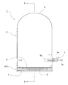
次に、図面に基づいて本考案の最良の実施形態を説明する。図1は本考案の風船構造体の第1実施形態を示す正面図、図2は図1のII− II断面図、図3は図1の底面側から見た展開図である。
風船構造体1は可撓性のプラスチックフィルム等の膜体で作られた密閉性で袋状の本体2と、本体2に設けた気体封入部3を備えており、本体2の表面にはイラストや写真等が印刷などにより表現される。
Next, preferred embodiments of the present invention will be described with reference to the drawings. FIG. 1 is a front view showing a first embodiment of a balloon structure according to the present invention, FIG. 2 is a sectional view taken along the line II-II in FIG. 1, and FIG.
The
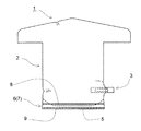
図1の風船構造体1は、本体2の内部に空気などの気体を封入して得られる立体的な風船形態を示しており、気体封入状態でその平断面は円形または楕円形であり、正面が上に円弧状の頭部4と下に円弧状の底面5を有している。本体2は薄い可撓性の透明、半透明または不透明なプラスチック膜体で作られ、全体が密封性の袋状に形成さている。なお風船形態としては上記のような平断面が円形,楕円形以外に方形等の立体形状も可能である。
The
気体封入部3は逆止弁機能を有する偏平な筒状フィルムからなる短管3aが本体2の下部を貫通する。その短管3aは、そのままでは気体が通過できないように2枚にプラスチックフィルムの表面が互いに密接に接触されている。本体2に気体を封入する際には、図示のように吹き込み用のストロー等のチューブ3cを短管3aの外側から内部まで挿入し、その吹き込みチューブ3cの端から空気などの気体を吹き込む。
In the
吹き込みチューブ3cを短管3aの先端部より、その途中まで挿入し、吹き込みチューブ3cを通して気体が本体2の内部に供給される。即ち、吹き込みチューブ3cから気体を吹き込むと、その吹き込み圧力で吹き込みチューブ3cより先の短管3bの密着した偏平部分の2枚のプラスチックフィルムが互いに離反し、気体がその離反した空間を通過して本体2の内部に供給される。そして気体封入後に吹き込みチューブ3cを引き抜くと、短管3bの主要部は本体2の内圧で周囲から偏平に圧着され、封入した気体は短管3b部分で阻止されて本体2の外部に漏洩することはない。
The blowing
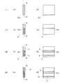
本考案の風船構造体1は、その底部5に着座部6が形成されている点に特徴がある。この着座部6は本体2の一部を折り返して形成される。図3はそのプラスチックフィルムの展開図の一例であり、図4(I)〜(IV)は、それを折り返して風船とする手順の要部説明図であり、(A)はその側面図、(B)は同正面断面図であって(A)のB―B 線断面矢視図である。
図3,図4を参照してその形成方法の例を説明すると、先ず、図3の展開図の中央線cで折り返して、図4(I) の状態にし、次いで中央線cを上方に引き上げて山折りにすると共に、図3の一対のkで谷折りにして図4(II) の状態にする。
The
An example of the forming method will be described with reference to FIGS. 3 and 4. First, it is folded at the center line c in the developed view of FIG. 3 to be in the state of FIG. 4 (I), and then the center line c is pulled upward. In addition to the mountain fold, a pair of k in FIG. 3 is used to fold the valley into the state shown in FIG. 4 (II).
次に、図4(III)のように、線cと線kとの間の二カ所づつで、プラスチックフィルムの2重部分を熱圧着などによりシールして互いに固着し、細長い第1固定部8および細長い第2固定部9を形成する。次いで、図4(IV)の如く、プラスチックフィルムの両側を熱圧着等によりシールして、第3固定部10を形成し、風船を完成する。
Next, as shown in FIG. 4 (III), the double portions of the plastic film are sealed by thermocompression bonding or the like at two points between the line c and the line k, and are fixed to each other. And the elongate 2nd fixing |
この状態で、本体2に気体を封入した状態が図1(及び図2)に示すような風船形態であり、本体2の底面5の周辺は環状となった第1固定部8と第2固定部9の2箇所で補強された状態となり、その2箇所の補強作用により安定した環状の着座部6が形成される。その際、第1固定部8は着座部6の上端部を補強し、第2固定部9は着座部6の下側を補強すると共に、そこから底面5が折り返されるための折り返し線を構成している。また本体2に気体を封入した状態で、その風船形態の底面5は前記着座部6より上方に位置するようになる。
In this state, the state in which gas is sealed in the
図2に示す中央の折れ線aは側部溶着線で、斜めの線bは底面5の両縁が側部溶着線に固定されたため、本体2に気体を封入したとき生じるものである。
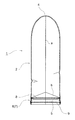
次に、図5は本考案の第2の実施の形態を示し、この例が図1の例と異なる点は、シールの幅であり、そのシールによる第1固定部8の幅が、図4(III)において、下端まで達したものである。
なお、シールによる第1固定部8等は、必ずしも全周に渡り環状に形成しなくてもよく、周方向にそって複数箇所、部分的に弧状に形成してもよい。要は、底部5が接地しないように、接地部を形成すればよい。図8はその例を示し、第1固定部8はその両端に溶着されない非固着部11を有している。なお、この例は図の表面側と裏面側とに一対の第1固定部が存在する。
A central broken line a shown in FIG. 2 is a side weld line, and an oblique line b is generated when gas is sealed in the
Next, FIG. 5 shows a second embodiment of the present invention. This example is different from the example of FIG. 1 in the width of the seal, and the width of the
Note that the
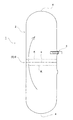
図6,図7は本考案の風船構造体の第3および第4の各実施形態を示す正面図であり、これらの実施形態は風船形態を立体的な衣服形状としたものであり、そのほかは第1実施形態と同様に構成される。従って風船形態は立体的な衣服形状同じ部分には同一符号を付し、重複する説明は省略する。 6 and 7 are front views showing the third and fourth embodiments of the balloon structure of the present invention. In these embodiments, the balloon shape is a three-dimensional clothing shape. The configuration is the same as in the first embodiment. Therefore, the same symbol is attached to the same part of the balloon shape in the three-dimensional clothing shape, and the overlapping description is omitted.
図6の風船構造体1は頭部が山形に形成された衣服形状であり、本体2の表面にイラストや写真等を印刷などにより描くことができる。図7の風船構造体1はTシャツのような衣服形状であり、図6同様に本体2の表面にイラストや写真等を印刷などにより描ける。
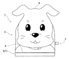
図9はその例を示し、上端に一対の耳が一体に突設された動物のキャラクタが描かれ、その耳の内部にも空気が供給されて、風船の一部となるものである。
The
FIG. 9 shows an example in which an animal character having a pair of ears protruding integrally at the upper end is drawn, and air is also supplied to the inside of the ear to become a part of a balloon.
本考案の風船構造体は、キャラクター宣伝用などに用いられる風船構造体として利用できる。 The balloon structure of the present invention can be used as a balloon structure used for character advertisements.
1 風船構造体
2 本体
3 気体封入部
3a,3b 短管
3c 吹き込みチューブ
DESCRIPTION OF
4 頭部
5 底面
6 着座部
7 周縁部
8 第1固定部
9 第2固定部
10 第3固定部
11 非固着部
4
10 3rd fixing part
11 Non-fixed part
Claims (4)
前記本体2の底面5の周縁に沿って弧状の着座部6が下方に突設され、前記本体2が立体的な風船形態を形成した際に、その風船形態の底面5が前記着座部6より上方に位置するようになっていることを特徴とする風船構造体。 A main body 2 is provided with a hermetically sealed bag-shaped main body 2 made of a flexible film body and a gas sealing portion 3 provided in the main body 2, and gas is sealed from the gas sealing portion 3 into the main body 2. In the balloon structure 1 in which 2 forms a three-dimensional balloon shape,
When the arcuate seating portion 6 projects downward along the peripheral edge of the bottom surface 5 of the main body 2 and the main body 2 forms a three-dimensional balloon shape, the balloon-shaped bottom surface 5 is more than the seating portion 6. A balloon structure characterized by being positioned above.
Priority Applications (1)
| Application Number | Priority Date | Filing Date | Title |
|---|---|---|---|
| JP2008001563U JP3142016U (en) | 2008-03-17 | 2008-03-17 | Balloon structure |
Applications Claiming Priority (1)
| Application Number | Priority Date | Filing Date | Title |
|---|---|---|---|
| JP2008001563U JP3142016U (en) | 2008-03-17 | 2008-03-17 | Balloon structure |
Publications (1)
| Publication Number | Publication Date |
|---|---|
| JP3142016U true JP3142016U (en) | 2008-05-29 |
Family
ID=43292048
Family Applications (1)
| Application Number | Title | Priority Date | Filing Date |
|---|---|---|---|
| JP2008001563U Expired - Lifetime JP3142016U (en) | 2008-03-17 | 2008-03-17 | Balloon structure |
Country Status (1)
| Country | Link |
|---|---|
| JP (1) | JP3142016U (en) |
-
2008
- 2008-03-17 JP JP2008001563U patent/JP3142016U/en not_active Expired - Lifetime
Similar Documents
| Publication | Publication Date | Title |
|---|---|---|
| ES2308363T3 (en) | DUST FILTER BAG. | |
| JP2009500251A (en) | Breathable bag | |
| JP3142016U (en) | Balloon structure | |
| JP6623007B2 (en) | Fusen | |
| WO1992021264A1 (en) | Bag made of plastic film having pattern drawn on inflated portion | |
| EP1750933B1 (en) | Folded alcohol beverage bag and method | |
| KR101622531B1 (en) | Balloon | |
| JP2004243111A (en) | Rigid balloon | |
| JP3144820U (en) | Packing bag for shape retention | |
| US20190315523A1 (en) | Self-supporting plastic bag and method for manufacturing same | |
| JPH0633984Y2 (en) | Polyhedral toy balloons | |
| ES2258498T3 (en) | FILTER BAG FOR A DUST VACUUM CLEANER. | |
| JP3062497U (en) | Air bag made of synthetic resin | |
| JP3239317U (en) | stick balloon | |
| JP3828893B2 (en) | Plastic balloon | |
| CN100438807C (en) | Clothes hanger | |
| JP3204902U (en) | Portable raincoat | |
| JP6023128B2 (en) | Double-sided bag | |
| JP5054173B2 (en) | mask | |
| JP2009250267A (en) | Film check valve and balloon structure | |
| JP2006219168A (en) | bag | |
| JP3205441U (en) | Plastic film bag | |
| JP2006273380A (en) | Sheet packaging method and sheet package | |
| JP3087784U (en) | Gas enclosure | |
| JP2006051053A (en) | Air cushion |
Legal Events
| Date | Code | Title | Description |
|---|---|---|---|
| R150 | Certificate of patent or registration of utility model |
Free format text: JAPANESE INTERMEDIATE CODE: R150 |
|
| FPAY | Renewal fee payment (event date is renewal date of database) |
Free format text: PAYMENT UNTIL: 20110507 Year of fee payment: 3 |
|
| R250 | Receipt of annual fees |
Free format text: JAPANESE INTERMEDIATE CODE: R250 |
|
| EXPY | Cancellation because of completion of term |