JP3143476U - Three-dimensional bicycle parking device - Google Patents
Three-dimensional bicycle parking device Download PDFInfo
- Publication number
- JP3143476U JP3143476U JP2008003059U JP2008003059U JP3143476U JP 3143476 U JP3143476 U JP 3143476U JP 2008003059 U JP2008003059 U JP 2008003059U JP 2008003059 U JP2008003059 U JP 2008003059U JP 3143476 U JP3143476 U JP 3143476U
- Authority
- JP
- Japan
- Prior art keywords
- upper rack
- bicycle
- support arm
- rack
- bicycle parking
- Prior art date
- Legal status (The legal status is an assumption and is not a legal conclusion. Google has not performed a legal analysis and makes no representation as to the accuracy of the status listed.)
- Expired - Lifetime
Links
- 229920001971 elastomer Polymers 0.000 claims description 4
- 239000005060 rubber Substances 0.000 claims description 4
- 238000009434 installation Methods 0.000 abstract description 5
- 230000002829 reductive effect Effects 0.000 description 4
- 238000000034 method Methods 0.000 description 3
- 230000006835 compression Effects 0.000 description 2
- 238000007906 compression Methods 0.000 description 2
- 239000004567 concrete Substances 0.000 description 2
- 230000000149 penetrating effect Effects 0.000 description 2
- 230000003014 reinforcing effect Effects 0.000 description 2
- 239000004744 fabric Substances 0.000 description 1
- 230000002452 interceptive effect Effects 0.000 description 1
- 239000002184 metal Substances 0.000 description 1
- 230000036961 partial effect Effects 0.000 description 1
- 230000003405 preventing effect Effects 0.000 description 1
- 239000011150 reinforced concrete Substances 0.000 description 1
- 230000000452 restraining effect Effects 0.000 description 1
- 230000002441 reversible effect Effects 0.000 description 1
- 230000001743 silencing effect Effects 0.000 description 1
- 230000000087 stabilizing effect Effects 0.000 description 1
Images


Landscapes
- Warehouses Or Storage Devices (AREA)
Abstract
【課題】設置のための省スペース化に寄与する立体駐輪装置を提供すること。
【解決手段】駐輪装置(1)は、基礎(3)上に互いに間隔をおいて建てられた複数の支柱(5)と、各支柱に水平に支持された支持アーム(7)と、各支持アームに支持された、自転車を載置するための上段のラック(9)と、下段のラック(11)とを備える。上段のラックは、支持アーム上をこれに沿って移動可能でありまた水平状態と下方に向けて傾斜した状態との間で揺動可能である。支持アームは、上段のラックより短い長さ寸法を有し、下段のラックは、上段のラックに対してこれと直交する水平方向へ移動可能であることを特徴とする。
【選択図】図1An object of the present invention is to provide a three-dimensional parking device that contributes to space saving for installation.
A bicycle parking device (1) includes a plurality of columns (5) that are built on a foundation (3) at intervals, a support arm (7) that is horizontally supported by each column, An upper rack (9) for placing a bicycle and a lower rack (11) supported by a support arm is provided. The upper rack is movable on the support arm along the rack, and can swing between a horizontal state and a downwardly inclined state. The support arm has a shorter length than the upper rack, and the lower rack is movable in a horizontal direction perpendicular to the upper rack.
[Selection] Figure 1
Description
本考案は、自転車のための駐輪装置、特に自転車を上下二段に載置、収容するための立体駐輪装置に関する。 The present invention relates to a bicycle parking device for a bicycle, and more particularly to a three-dimensional bicycle parking device for mounting and housing a bicycle in two upper and lower stages.
従来、例えば集合住宅の敷地内における駐輪スペースの有効活用を図るため、自転車を上下二段に載置することができる立体駐輪装置が提案されている(後記特許文献1参照)。この駐輪装置は、基礎上に建てられた複数の支柱と、前記基礎の上方空間に配置されかつ各支柱に支持された支持アームと、各支持アームに水平に支持され該支持アームに沿って伸びる、自転車を載置するための上段のラックであって前記支持アーム上を移動可能でありかつ水平な状態と下方に向けて傾斜した状態との間で揺動可能である上段のラックと、前記基礎上に互いに間隔をおいて設置、固定され、前記上段のラックと平行に伸びる、自転車を載置するための複数の下段のラックとを備える。上下各段のラックは、通常、標準的な自転車の全長にほぼ等しい長さ寸法又はこれよりもわずかに長い長さ寸法を有し、自転車は前記支柱に向けられた状態で各ラック上に載置される。
2. Description of the Related Art Conventionally, for example, a three-dimensional bicycle parking apparatus has been proposed that can place bicycles in two upper and lower stages in order to effectively use a bicycle parking space in a premises of an apartment house (see
この駐輪装置にあっては、駐輪のために地上の自転車を前記上段のラック上に載せるに際して、又は前記上段のラック上に載置された自転車を地上に降ろすに際して、前記支持アーム上において水平に伸びる状態にある前記上段のラックを前記支持アームに対して揺動させ、該支持アームと角度をなして下方へ伸びるように傾斜する状態におかれる。駐輪に際しては、その利用者が、傾斜した上段のラック上に自転車の前輪を載せ、前進移動させて自転車の両輪を前記上段のラック上に載せた後、前記上段のラックを水平状態にすべくその端部を上方に向けて押し上げて揺動させ、水平状態にされた前記ラックを前記支柱へ向けて移動させることにより行われる。また、前記上段のラック上に載置された自転車を地上に降ろすときは、前記支持アーム上の前記上段のラックを前記支柱から離れる方向へ移動させた後、前記上段のラックを傾斜状態にすべくその端部を引き下げて揺動させ、さらに、前記上段のラック上から地上へと自転車を後退移動させることにより行われる。 In this bicycle parking apparatus, when the bicycle on the ground is placed on the upper rack for parking, or when the bicycle placed on the upper rack is lowered onto the ground, the bicycle is mounted on the support arm. The upper rack in a horizontally extending state is swung with respect to the support arm and is inclined so as to extend downward at an angle with the support arm. When parking, the user puts the front wheel of the bicycle on the inclined upper rack, moves it forward and places both bicycle wheels on the upper rack, and then puts the upper rack in a horizontal state. Therefore, it is carried out by pushing the end of the rack upward and swinging it, and moving the rack in a horizontal state toward the column. In addition, when the bicycle placed on the upper rack is lowered to the ground, the upper rack on the support arm is moved away from the column, and then the upper rack is inclined. Therefore, it is carried out by pulling down the end portion of the bicycle and swinging it, and further moving the bicycle backward from the upper rack to the ground.
また、前記従来の駐輪装置にあっては、前記支持アームの長さ寸法が、自転車の全長にほぼ等しい長さ寸法を有する前記上段のラックの長さ寸法にほぼ等しいものに設定されている。これにより、前記上段のラックを、前記下段のラック上に載置された自転車の後部上方まで案内し、揺動させることにより、前記上段のラックが前記下段のラック上の自転車に当たることなく該自転車の上方をその後方に向けて伸び、前記上段のラックの端部(下端部)が前記自転車の後方に位置することとなるように前記上段のラックを傾斜させることができる。
ところで、前記従来の駐輪装置は、自転車を上下方向に配置可能とすることにより、自転車を平置きとする場合と比べて、その水平方向における設置スペースの削減に寄与すると考えられる。しかし、反面、自転車の入出庫の際における前記支持アームからの前記上段のラックの突出を許容する水平方向の空間を必要とし、その突出長が自転車のほぼ全長に相当するものであり、前記駐輪装置のための設置スペースの削減は実質的には制限されるという問題がある。 By the way, it is considered that the conventional bicycle parking apparatus contributes to the reduction of the installation space in the horizontal direction by enabling the bicycle to be arranged in the vertical direction as compared with the case where the bicycle is placed flat. However, it requires a horizontal space that allows the upper rack to protrude from the support arm when the bicycle is loaded and unloaded, and the protruding length corresponds to substantially the entire length of the bicycle. There is a problem that the reduction of the installation space for the wheel apparatus is substantially limited.
本考案の目的は、設置のための省スペース化に寄与する立体駐輪装置を提供することにある。 An object of the present invention is to provide a three-dimensional bicycle parking device that contributes to space saving for installation.
(請求項1に記載の考案の特徴)
請求項1に記載の考案は、駐輪装置に係り、基礎上に互いに間隔をおいて建てられた複数の支柱と、各支柱に水平に支持された支持アームと、各支持アームに支持された、自転車を載置するための上段のラックであって前記支持アーム上を該支持アームに沿って移動可能でありかつ水平な状態と下方に向けて傾斜した状態との間で揺動可能である上段のラックと、前記基礎上に設置され、前記上段のラックと平行に伸びる、自転車を載置するための複数の下段のラックとを含み、前記支持アームは、前記上段のラックより短い長さ寸法を有し、前記下段のラックは、前記上段のラックに対してこれと直交する水平方向へ移動可能であることを特徴とする。
(Characteristics of the device according to claim 1)
The invention according to
請求項1に記載の考案によれば、駐輪のために自転車を地上から上段のラック上に載せるに際し、又は駐輪中の自転車を前記上段のラック上から地上に降ろすに際し、従来におけると同様、前記上段のラックが水平状態から傾斜状態におかれる。駐輪は、前記傾斜状態におかれた上段のラック上に自転車を前進移動させて載せ、自転車が載せられた前記上段のラックを水平状態におき、さらに前記上段のラックを前記支柱へ向けて前記支持アーム上をこれに沿って移動させることにより行うことができる。他方、前記上方のラック上の自転車を地上に降ろすときは、自転車が載せられた前記上段のラックを前記支持アームに沿って前記支柱から離れる方向へ移動させ、次いで前記上段のラックを水平状態から傾斜状態に移行させ、さらに、傾斜状態にある前記上段のラック上から自転車を後退移動させることにより行うことができる。 According to the first aspect of the present invention, when a bicycle is placed on the upper rack from the ground for parking, or when the bicycle being parked is lowered from the upper rack to the ground, the same as in the past. The upper rack is placed in an inclined state from a horizontal state. In the parking, the bicycle is moved forward and placed on the upper rack placed in the inclined state, the upper rack on which the bicycle is placed is placed in a horizontal state, and the upper rack is directed toward the column. This can be done by moving along the support arm. On the other hand, when the bicycle on the upper rack is lowered to the ground, the upper rack on which the bicycle is placed is moved along the support arm in a direction away from the support column, and then the upper rack is moved from the horizontal state. It can be performed by shifting to the inclined state and further moving the bicycle backward from the upper rack in the inclined state.
本考案にあっては、前記上段のラックを支持する前記支持アームの長さ寸法が前記上段のラックの長さ寸法より短いものとされていることから、従来の駐輪装置に比べて、前記支持アーム上に沿っての前記上段のラックの移動距離をより短くし、前記上段のラックの移動に伴う前記支持アームからの前記上段のラックの突出長さをより小さいものに抑えることができ、その結果、駐輪装置の設置に要する水平方向におけるスペースを実質的に低減することができる。 In the present invention, since the length dimension of the support arm that supports the upper rack is shorter than the length dimension of the upper rack, compared with the conventional bicycle parking device, The movement distance of the upper rack along the support arm can be shortened, and the protruding length of the upper rack from the support arm accompanying the movement of the upper rack can be suppressed to a smaller one. As a result, the horizontal space required for installing the bicycle parking apparatus can be substantially reduced.
ところで、前記支持アームの長さ寸法が前記上段のラックの長さ寸法より短いものとされた結果、前記上段のラックが傾斜状態へと揺動されるとき、前記上段のラックの下端は、従来におけるような下段のラックに載置された自転車の後方ではなく、前記下段のラック上の自転車の前後輪間に位置することとなる。本考案にあっては、前記下段のラックが、前記上段のラックに対してこれと直交する水平方向へ移動可能とされていることから、前記下段のラックを移動させることにより、前記上段のラックの揺動のための空間及び該上段のラックに対する自転車の入出庫のための空間を前記基礎上に確保することができる。このことにより、さらに、前記下段のラック上に載置された自転車の後方空間が比較的狭い場合にあっても、これに拘わらず、前記上段のラック上への自転車の入出庫作業を可能とすることができる。 By the way, as a result of the length dimension of the support arm being shorter than the length dimension of the upper rack, when the upper rack is swung into an inclined state, the lower end of the upper rack is It is located between the front and rear wheels of the bicycle on the lower rack, not behind the bicycle placed on the lower rack as shown in FIG. In the present invention, since the lower rack is movable in a horizontal direction perpendicular to the upper rack, the upper rack can be moved by moving the lower rack. A space for swinging the vehicle and a space for loading and unloading the bicycle with respect to the upper rack can be secured on the foundation. As a result, even when the rear space of the bicycle placed on the lower rack is relatively narrow, the bicycle can be loaded and unloaded on the upper rack regardless of this. can do.
(請求項2に記載の考案の特徴)
請求項2に記載の考案は、請求項1に記載の考案の構成要素を備えた上で、さらに、前記支持アームに枢着された一端部と前記上段のラックに係合され前記支持アームに対する前記上段のラックの移動を許す他端部とを有するバー部材と、前記支持アーム及び前記バー部材にそれぞれ枢着された両端部を有する被圧縮のエアシリンダ又はばね部材とを備えることを特徴とする。
(Characteristics of the device according to claim 2)
The invention described in claim 2 is provided with the components of the invention described in
請求項2に記載の考案によれば、圧縮状態におかれたエアシリンダ又はばね部材の復帰力が、前記バー部材を介して、前記上段のラックに対してこれが水平状態から傾斜状態へと揺動することを妨げるように作用する。この復帰力は、前記上段のラックをこれが傾斜状態へと至る方向へ揺動させることによって生じる前記エアシリンダ又はばね部材の圧縮量の増大に伴って増大する。増大した前記復帰力は、前記傾斜状態にある上段のラック部材に自転車を載せた後、これを水平状態に戻すべく上方に向けて揺動させるのに要する力を軽減することに役立つ。 According to the second aspect of the present invention, the restoring force of the air cylinder or the spring member placed in the compressed state swings from the horizontal state to the inclined state with respect to the upper rack via the bar member. It acts to prevent it from moving. This restoring force increases with an increase in the compression amount of the air cylinder or the spring member generated by swinging the upper rack in the direction in which the upper rack is inclined. The increased restoring force helps to reduce the force required to swing the bicycle upwards to return it to the horizontal state after the bicycle is placed on the upper rack member in the inclined state.
(請求項3に記載の考案の特徴)
請求項3に記載の考案は、請求項1又は2に記載の考案の構成要素を備えた上で、さらに、前記上段のラック上に配置され該上段のラックに沿って走行可能である、自転車の前輪を載せるための台車を含むことを特徴とする。
(Characteristics of the device according to claim 3)
The invention according to
請求項3に記載の考案によれば、前記傾斜状態にある上段のラック上への載置のために自転車を押して前進移動させるとき、前記自転車の前輪を前記上段のラック上を転動可能である前記台車に乗せることにより、前記自転車の前進移動を該自転車の前後輪が前記上段のラック上を転動するようにして行う場合と比べて、前記自転車を押すのに要する力を軽減することができる。 According to the third aspect of the present invention, when the bicycle is pushed forward for placement on the upper rack in the inclined state, the front wheel of the bicycle can roll on the upper rack. By placing the bicycle on a certain carriage, the force required to push the bicycle is reduced as compared to the case where the bicycle moves forward and backward on the upper rack. Can do.
(請求項4に記載の考案の特徴)
請求項4に記載の考案は、請求項3に記載の考案の構成要素を備えた上で、さらに、前記台車及び前記上段のラックにそれぞれ設けられた自転車の前輪保持枠及び後輪保持枠を含み、前記後輪保持枠が、前記上段のラックが傾斜状態にあるとき、前記自転車の前輪を一時的に載せることが可能である載置部を備えることを特徴とする。
(Characteristics of the device according to claim 4)
The invention described in claim 4 comprises the components of the invention described in
請求項4に記載の考案によれば、前記上段のラックに載置された自転車の前後輪をそれぞれ前記前輪保持枠及び後輪保持枠に保持し、駐輪中における前記自転車の転倒を防止することができる。また、前記傾斜状態にある上段のラックに自転車を載せるとき、前記後輪保持枠の載置部上に前記自転車の前輪を一時的に載せることにより前記自転車の姿勢の安定化を図ることができるため、これに引き続く前記上段のラック上における前記自転車の前進移動操作をよりスムーズに行うことができる。 According to a fourth aspect of the present invention, the front and rear wheels of the bicycle placed on the upper rack are held by the front wheel holding frame and the rear wheel holding frame, respectively, to prevent the bicycle from toppling during parking. be able to. Further, when the bicycle is placed on the upper rack in the inclined state, the posture of the bicycle can be stabilized by temporarily placing the front wheel of the bicycle on the placement portion of the rear wheel holding frame. Therefore, the forward movement operation of the bicycle on the upper rack following this can be performed more smoothly.
(請求項5に記載の考案の特徴)
請求項5に記載の考案は、請求項1〜4のいずれか1項に記載の構成要素を備えた上で、前記支柱は、複数の防震ゴムを介して、前記基礎に固定されていることを特徴とする。
(Characteristics of the device according to claim 5)
The invention according to
請求項5に記載の考案によれば、前記上段のラックの前記支持アームに対する移動操作、前記上段ラックを前記水平状態及び傾斜状態にするための前記上段のラックの揺動操作等に伴って生じる打撃音が前記基礎を通じて例えば鉄筋コンクリート製の集合住宅に伝達することを低減する消音効果を得ることができる。 According to the fifth aspect of the invention, it occurs in association with a movement operation of the upper rack with respect to the support arm, a swinging operation of the upper rack to bring the upper rack into the horizontal state and the inclined state, and the like. It is possible to obtain a silencing effect that reduces the impact sound transmitted to the apartment house made of, for example, reinforced concrete through the foundation.
本考案によれば、設置のための省スペース化に寄与する立体駐輪装置を提供することができる。 According to the present invention, it is possible to provide a three-dimensional bicycle parking device that contributes to space saving for installation.
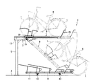
図1及び図2を参照すると、本考案に係る駐輪装置が全体に符号1で示されている。駐輪装置1は、基礎3上に互いに間隔をおいて建てられ上下方向に伸びる複数の支柱5を備える。これらの支柱5には、基礎3の上方空間に配置され互いに平行に伸びる複数の支持アーム7が水平に支持されている。各支持アーム7には、自転車Bを載置するための上段のラック9が支持され、また、基礎3上には、上段のラック9と平行に伸びる、自転車Bを載置するための複数の下段のラック11が設置されている。上段のラック9は、支持アーム7上を該支持アームに沿って移動可能とされ、また水平な状態(図1参照)と、下方に向けて傾斜した状態(図2参照)との間で揺動可能とされている。
Referring to FIGS. 1 and 2, a bicycle parking apparatus according to the present invention is generally indicated by
図1には、駐輪装置1の上段のラック9及び下段のラック11にそれぞれ想像線で示す自転車Bが載置されている状態が示されている。また、図2には、上段のラック9に載置された自転車Bが地上に降ろされるときの状態が示されている。上下段の両ラック9,11は、それぞれ、標準的な大きさの自転車Bの全長にほぼ等しい長さ寸法又はこれよりもわずかに長い寸法を有する。
FIG. 1 shows a state in which bicycles B indicated by imaginary lines are placed on the
図1に示すように、自転車Bが載置された上段のラック9は支持アーム7上において水平な状態にあり、また支柱5に近接した位置にある。自転車Bを地上に降ろすとき、すなわち駐輪装置1から自転車Bを出庫するときは、図2に示すように、上段のラック9を支柱5から次第に離れるように支持アーム7に沿って移動させたのち、上段のラック9を揺動させてこれを下方に向けて傾斜する状態、すなわち支持アーム7に対して角度をなして下方へ伸びる状態にする。上段のラック9の傾斜の急緩の程度は、上段のラック9及び支持アーム7の双方の長さ寸法を考慮して定めることができる。また、図示の例では、上段のラック9を傾斜させたとき、上段のラック9の下端部(後記他端部29)が基礎3の上方にわずかな間隔をおいて位置するように設定されている。傾斜状態にある上段のラック9から自転車Bを後退移動させることにより、自転車Bを地上に降ろすことができる。自転車Bを地上に降ろした後の上段のラック9は、該上段のラックに自転車Bを載置するための後記手順と同様の手順に従って、元の水平な状態に戻すことができる。
As shown in FIG. 1, the
地上の自転車Bを上段のラック9上に載置するとき、すなわち駐輪装置1への自転車Bの入庫に当たっては、まず、元の水平な状態に戻された上段のラック9を、上段のラック9から自転車Bを地上に降ろす前記手順と同様の手順に従って、下方に向けて傾斜する状態におく。次に、自転車Bを前進移動させて上段のラック9上に載せる。その後、上段のラック9をこれが水平状態となるまで反対方向に揺動させ、水平状態にされた上段のラック9を支柱5に向けて支持アーム7上を移動させる。これにより、地上の自転車Bを上段のラック9上に載置することすることができる。
When the bicycle B on the ground is placed on the
他方、下段のラック11上に載置された自転車Bは、下段のラック11上を後退移動させることにより基礎3上に降ろすことができ、また下段のラック11上への自転車Bの載置は、基礎3上から自転車Bの前輪tを下段のラック11上に載せ、これを前進移動させることにより行うことができる。
On the other hand, the bicycle B placed on the
本考案にあっては、上段のラック9は、前記したように、これに自転車Bを載置することが可能であるように自転車Bの全長にほぼ等しい長さ寸法又はこれよりも長い長さ寸法を有するところ、上段のラック9を支持する支持アーム7は上段のラック9より短い長さ寸法を有する。支持アーム7の長さ寸法についてこのように設定することにより、上段のラック9の長さを支持アーム7の長さとほぼ同じものに設定する場合と比べて、上段のラック9を傾斜状態に移行させるに先立って支持アーム7に沿って支柱5から遠ざける方向へ移動させたときの上段のラック9の移動量、すなわち支持アーム7からの上段のラック9の突出量を少なくすることができる。また、支持アーム7の長さと該支持アームから引き出され水平に伸びる上段のラック9の長さとの和を従来よりも小さくすることができるということもできる。これにより、支持アーム7からの上段のラック9の引き出しのために予め確保されていなければならない空間の大きさの低減を図ることができる。
In the present invention, as described above, the
また、上段のラック9の長さ寸法を支持アーム7より短いものとした結果、下段のラック11上に載置された自転車Bは、上段のラック9の水平状態及び傾斜状態間での揺動運動並びにこれに伴う上段のラック9に対する自転車Bの載せ降ろし作業の妨げとなる。本考案にあっては、図3に示すように、下段のラック11が上段のラック9に対してこれと直交する水平方向へ移動可能とされている。このことから、揺動運動をする上段のラック9下に位置する下段のラック11及びその近傍の他の下段のラック11をこれらに載置された自転車Bと共に移動させ、上段のラック9の下方に、その揺動運動及び上段ラック9上への自転車Bの載せ降ろしを行うための空間を確保することができる。
Further, as a result of making the length of the
支柱5が建てられる基礎3は、駐輪装置1が屋外に設置される場合には地面、地面上に形成されたコンクリート製の布基礎等からなり、また、屋内に設置される場合には建物の床等からなる。
The
支柱5に片持ち支持された支持アーム7は、基端部13と自由端部15とからなる両端部を有し、その基端部13において支柱5の上部に固定されている。支持アーム7には、これに沿って伸びかつ上方に向けて開放する一条の凹溝17が設けられている。符号19及び21は、支柱5による支持アーム7の支持を補強するための補強部材を示す。
The
自転車Bが載置される上下段の両ラック9,11は、それぞれ、上方に向けて開放する、自転車Bの前後輪tの一部を受け入れ可能である一条の凹溝23,25を有する。自転車Bは、前後方向に整列された前後輪tの一部が各ラック9,11の凹溝23,25内に受け入れられ、後述する保持枠49〜55による支持の下で、自立した状態で各ラック9,11上に載置される。
Both the upper and
上段のラック9は、該上段ラック上への自転車Bの載せ降ろしのために、前記したように、支持アーム7上をその伸張方向へ移動可能とされている。より詳細には、図4、図5及び図1に示すように、上段のラック9は一端部27と他端部29とを有し、一端部27は支持アーム7の凹溝17内に受け入れられ、他端部29は支持アーム7の凹溝17からその外部に突出している。上段のラック9は、その一端部27において支持アーム7の基端部13と自由端部15との間で移動可能とされている。
As described above, the
支持アーム7上における上段のラック9の移動をより円滑にし、またより小さい力で移動させることができるようにすべく、上段のラック9の一端部27に一対の車輪31が取り付けられている。また、両車輪31のための上下走行面を規定する、上下方向に関して互いに相対する上下二対のフランジ33,34が支持アーム7に設けられている(図5)。両車輪31は、上段のラック9を貫通してこれを横断する方向へ伸びる軸35を介して上段のラック9に回転可能に支持されている。
A pair of
下方の両フランジ33は、支持アーム7の凹溝17内において、該凹溝を規定する支持アーム7の両側壁から互いに他の一方に向けて張り出しかつ支持アーム7の伸張方向へ伸びている。また、上方の両フランジ34は、支持アーム7の両側壁から互いに他の一方に向けて張り出しかつ支持アーム7の伸張方向へ伸び、凹溝17の上部開放面を規定している。
The
上段のラック9は、その一端部27において、支持アーム7の凹溝17内に受け入れられているとき、水平な状態におかれる。上段のラック9は、これに取り付けられた車輪31の軸35の周りに揺動可能とされている。支持アーム7の自由端部15での上段のラック9の揺動を可能とするため、支持アーム7の自由端部15の底面に、支持アーム7の凹溝17に連通する切り欠き39が設けられている。切り欠き39は、上段のラック9がその他端部29を下にして傾斜することを許すいわゆる逃げの空間を規定する。さらに、支持アーム7の自由端部15からの上段のラック9の抜け出しを阻止するため、支持アーム7の自由端部15内に、車輪31の軸35が当接可能であるストッパ41(図6及び図7参照)が設けられている。ストッパ41は、後述する一対のブラケット71により規定されている。上段のラック9は、切り欠き39の存在、上下のフランジ33,34による車輪31の拘束作用及びストッパ41による車輪31の移動阻止作用のもと、支持アーム7の自由端部15での上段のラック9の揺動運動が可能とされている。
The
図3に示すように、下段のラック11は、上段のラック9に対してこれに直交する方向への移動を可能とするため、基礎3上に設置された互いに平行な一対のレール43上にこれらの長手方向へ移動可能に載置されている。図1及び図2に示すように、下段のラック11には、その下面の二箇所のそれぞれに、各レール43の側面にこれを転動可能に当接する一対のローラ45,47が取り付けられている。これらのローラ45,47は、下段のラック11が各レール43の長手方向のみへの移動を許すように下段のラック11を規制すると共に、下段のラック11の各レール43に沿っての移動をより円滑にする機能を有する。また、互いに隣接する2つの下段のラック11は、両ラック11の長手方向に関して位置がずれているように配置されている。これにより、両ラック11に載置される自転車Bに取り付けられた篭b同士が干渉し合うことを防止することができる。
As shown in FIG. 3, the
上下段の両ラック9,11には、それぞれ、これらのラック上で自転車Bが自立するように該自転車の前後輪tの一部を受け入れ可能である前後の保持枠49,51、53,55が取り付けられている。なお、図示の例では、上段のラック9の前輪用保持枠49は、後述する台車に設けられている。自転車Bの前後輪tはこれらをそれぞれ持ち上げて前記保持枠内にその上方から挿入することができる。上段のラック9の後輪用保持枠51には、特に、傾斜状態にある上段のラック9に自転車Bを載置する際の該自転車の前進移動及び上段のラック9から自転車Bを降ろす際の該自転車の後退移動を行うに先立ち、自転車Bの前輪tを一時的に載せ置き、これにより自転車Bの姿勢を安定させることに寄与するU字形の平面形状を有する載置部57が設けられている。また、後輪用保持枠51は、上段のラック9を揺動させるときにその他端部29を引き下げるための手がかりとして利用することができる。
The upper and
上段のラック9上には、該上段のラックに沿って走行可能である、自転車Bの前輪tを載せるための台車59が配置されている。上段のラック9の一端部27及び他端部29には、台車59の移動をこれらの両端部27,29間に制限するためのストッパ(図示せず)が取り付けられている。台車59は、上段のラック9の凹溝23の底面上を転動可能である二対の車輪61を有する。台車59は、自転車Bを傾斜した上段のラック9上で前進移動させるときの労力軽減に役立つ。
On the
また、支持アーム7と上段のラック9とには、それぞれ、係止板63及び係止棒65が取り付けられている。係止板63は支持アームの自由端部15の側面に設けられている。また、係止棒65は折り曲げ両端部を有し、上段のラック9の側面にその軸線の周りに回転可能に保持されている。駐輪のために上段のラック9に自転車Bが載置されているとき、係止板63に対する係止棒65の一方の折り曲げ端部の係止により、上段のラック9の支持アーム7の自由端部15へ向けての移動が阻止される。係止板63に対する係止棒65の係止の解除は、係止棒65をその一方の折り曲げ端部が係止板63に対して非接触状態となるまでその軸線の周りに回転させることにより行うことができる。
A locking
図5〜図8を参照すると、さらに、バー部材67と、被圧縮状態におかれたエアシリンダ69とが設けられている。
5 to 8, a
バー部材67は、一対のブラケット71を介して支持アーム7に枢着された一端部73と、上段のラック9に係合され、上段のラック9の移動を許す他端部75とを有する。
The
両ブラケット71は支持アーム7の自由端部15に配置されている。両ブラケット71は、これらのブラケット71に連なりかつ支持アーム7の凹溝17内を自由端部15から基端部13に向けて伸びる伸張部77を有する。両ブラケット71は、伸張部77を介して、支持アーム7に固定されている。両ブラケット71は、その一部が支持アーム7の凹溝17内と上段のラック9に設けられその下方に向けて開放する他の凹溝79(図5)内とに存し、両ブラケット71の他の部分、すなわち支持アーム7の自由端部15から突出する残りの部分が、支持アーム7の切り欠き39の近傍に向けて下方へ伸びている。
Both
バー部材67の一端部73は両ブラケット71の間に配置され、これらを貫通する軸81を介して両ブラケット71に枢着されている。軸81の両端部には、それぞれ、軸81の周りに回転可能である一対の車輪83が取り付けられている。両車輪83は、一対の段部85と一対のフランジ87とを走行面とする(図5及び図7参照)。一対の段部85は、上段のラック9の下方に向けて開放する凹溝79の両側壁に設けられている。また、一対のフランジ87は、凹溝79の開放下面を規定するように互いに他の一方に向けて張り出している。同様に、バー部材67の他端部75にもこれを貫通する軸89と、軸89の両端部に取り付けられ両段部85及び両フランジ87を上下走行面とする一対の車輪91とが設けられている。バー部材67の他端部75は、これに取り付けられた両車輪91を介して、上段のラック9の両段部85及び両フランジ87に係合されており、支持アーム7に対する上段のラック9の前記移動を許す。
One
被圧縮状態にあるエアシリンダ69は、上段のラック9が水平状態にあるときにバー部材67の他端部75から両ブラケット71に向けて斜め下方に伸びるように配置されている。エアシリンダ69は、その両端部93,95において、2つのピン97,99を介して、バー部材67の他端部75と両ブラケット71とに枢着されている。
The
これによれば、支持アーム7の自由端部15まで移動された上段のラック9に対して、被圧縮状態におかれたエアシリンダ69の復帰力又は復元力が作用する。これにより、上段のラック9が水平な状態に維持される。また、上段のラック9を揺動させてこれを前記傾斜状態におくと、エアシリンダ69の全長がより減少し、エアシリンダ69における被圧縮の程度がさらに増大される。これに伴って、上段のラック9に対するエアシリンダ69の前記復帰力が増大する。この復帰力は、前記傾斜状態において自転車Bが載置された上段のラック9を水平状態に戻すべくこれを揺動させるための補助力として利用することができる。エアシリンダ69に代えて、被圧縮状態におかれたコイルスプリングのようなばね部材を用いることができる。
According to this, the restoring force or restoring force of the
なお、基礎3と各支柱5との間に防震ゴム(図示せず)を配置することが望ましい。前記防震ゴムは、駐輪の際の上下段の各ラック9,11の移動に伴って生じる衝突音や、金属音等についての消音に寄与し、さらに基礎3を介しての集合住宅のようなコンクリート構造物への音の伝搬を防止することができる。
In addition, it is desirable to arrange an anti-seismic rubber (not shown) between the
1 駐輪装置
3 基礎
5 支柱
7 支持アーム
9 上段のラック
11 下段のラック
49,53 前輪用保持枠
51,55 後輪用保持枠
57 載置部
59 台車
67 バー部材
69 エアシリンダ
DESCRIPTION OF
Claims (5)
各支柱に水平に支持された支持アームと、
各支持アームに支持された、自転車を載置するための上段のラックであって前記支持アーム上を該支持アームに沿って移動可能でありかつ水平な状態と下方に向けて傾斜した状態との間で揺動可能である上段のラックと、
前記基礎上に設置され、前記上段のラックと平行に伸びる、自転車を載置するための複数の下段のラックとを含み、
前記支持アームは、前記上段のラックより短い長さ寸法を有し、
前記下段のラックは、前記上段のラックに対してこれと直交する水平方向へ移動可能である、
ことを特徴とする、駐輪装置。 A plurality of struts built on the foundation at a distance from each other;
A support arm supported horizontally on each column;
An upper rack supported by each support arm for placing a bicycle, which is movable on the support arm along the support arm and has a horizontal state and a downward inclined state. An upper rack that can swing between,
A plurality of lower racks for mounting a bicycle, installed on the foundation and extending in parallel with the upper rack;
The support arm has a shorter length than the upper rack,
The lower rack is movable in a horizontal direction perpendicular to the upper rack,
This is a bicycle parking device.
ことを特徴とする、請求項1に記載の駐輪装置。 And a bar member having one end pivotally attached to the support arm and the other end engaged with the upper rack and allowing the upper rack to move relative to the support arm, and the support arm and the bar member. A compressed air cylinder or spring member having opposite ends pivotally attached to each other.
The bicycle parking device according to claim 1, wherein:
ことを特徴とする、請求項1又は2に記載の駐輪装置。 And a carriage for placing a front wheel of the bicycle, which is disposed on the upper rack and is capable of traveling along the upper rack.
The bicycle parking apparatus according to claim 1, wherein the bicycle parking apparatus is characterized.
前記後輪用保持枠が、前記上段のラックが傾斜状態にあるとき、前記自転車の前輪を一時的に載せることが可能である載置部を備える、
ことを特徴とする、請求項3に記載の駐輪装置。 In addition, the bicycle includes a front wheel holding frame and a rear wheel holding frame provided on the carriage and the upper rack, respectively.
The rear wheel holding frame includes a mounting portion on which the front wheel of the bicycle can be temporarily mounted when the upper rack is in an inclined state;
The bicycle parking device according to claim 3, wherein:
ことを特徴とする、請求項1〜4のいずれか1項に記載の駐輪装置。 The support column is fixed to the foundation via a plurality of seismic rubbers.
The bicycle parking apparatus according to any one of claims 1 to 4, wherein the bicycle parking apparatus is characterized.
Priority Applications (1)
| Application Number | Priority Date | Filing Date | Title |
|---|---|---|---|
| JP2008003059U JP3143476U (en) | 2008-05-13 | 2008-05-13 | Three-dimensional bicycle parking device |
Applications Claiming Priority (1)
| Application Number | Priority Date | Filing Date | Title |
|---|---|---|---|
| JP2008003059U JP3143476U (en) | 2008-05-13 | 2008-05-13 | Three-dimensional bicycle parking device |
Publications (1)
| Publication Number | Publication Date |
|---|---|
| JP3143476U true JP3143476U (en) | 2008-07-24 |
Family
ID=43293407
Family Applications (1)
| Application Number | Title | Priority Date | Filing Date |
|---|---|---|---|
| JP2008003059U Expired - Lifetime JP3143476U (en) | 2008-05-13 | 2008-05-13 | Three-dimensional bicycle parking device |
Country Status (1)
| Country | Link |
|---|---|
| JP (1) | JP3143476U (en) |
Cited By (4)
| Publication number | Priority date | Publication date | Assignee | Title |
|---|---|---|---|---|
| JP2016014311A (en) * | 2014-06-11 | 2016-01-28 | 株式会社Oss | Bicycle parking machine |
| JP2017505392A (en) * | 2014-01-20 | 2017-02-16 | クォン、ヨン−チョンKWON, Yeong−Jong | High-rise mobile automated bicycle storage |
| CN107401300A (en) * | 2017-08-29 | 2017-11-28 | 厦门烽火互动科技有限公司 | A kind of stereo-parking shed of bicycles |
| CN115478723A (en) * | 2022-10-10 | 2022-12-16 | 上海工程技术大学 | Double-layer non-motor vehicle parking device |
-
2008
- 2008-05-13 JP JP2008003059U patent/JP3143476U/en not_active Expired - Lifetime
Cited By (4)
| Publication number | Priority date | Publication date | Assignee | Title |
|---|---|---|---|---|
| JP2017505392A (en) * | 2014-01-20 | 2017-02-16 | クォン、ヨン−チョンKWON, Yeong−Jong | High-rise mobile automated bicycle storage |
| JP2016014311A (en) * | 2014-06-11 | 2016-01-28 | 株式会社Oss | Bicycle parking machine |
| CN107401300A (en) * | 2017-08-29 | 2017-11-28 | 厦门烽火互动科技有限公司 | A kind of stereo-parking shed of bicycles |
| CN115478723A (en) * | 2022-10-10 | 2022-12-16 | 上海工程技术大学 | Double-layer non-motor vehicle parking device |
Similar Documents
| Publication | Publication Date | Title |
|---|---|---|
| JP3143476U (en) | Three-dimensional bicycle parking device | |
| KR102259364B1 (en) | Device for supporting side gate of truck | |
| JP4503146B2 (en) | Moving ladder device for shelves | |
| JP3466068B2 (en) | Bicycle parking device | |
| JP2009202723A (en) | Stand device for two-wheeler | |
| JPH056235Y2 (en) | ||
| JP5103263B2 (en) | Motorcycle stand | |
| JP4663415B2 (en) | Bicycle three-dimensional bicycle parking device | |
| JP3166761B2 (en) | Platform support device for freight vehicles | |
| JP4493105B1 (en) | Bicycle parking equipment | |
| JP2009040297A (en) | Parking device for bicycle | |
| JP2003220985A (en) | Bicycle parking device | |
| JP2001234638A (en) | Bicycle parking device | |
| JP2002274458A (en) | Parking equipment | |
| JPH0821117A (en) | Bicycle parking device | |
| JP2003063466A (en) | Bicycle parking device | |
| JP2551415Y2 (en) | Bicycle parking device | |
| JP2004268724A (en) | Bicycle parking device | |
| JPS5863531A (en) | Carrier sliding type truck | |
| JP3084595B2 (en) | Traveling device for flat platform mobile bleachers | |
| JP3080155U (en) | Pole stand for truck bed | |
| JP2004042798A (en) | Motorcycle parking device | |
| JPH0716850Y2 (en) | Hanging type bicycle parking device | |
| JPH08284453A (en) | Bicycle parking device | |
| JP2004098961A (en) | Step plate operation mechanism in vehicle carrier |
Legal Events
| Date | Code | Title | Description |
|---|---|---|---|
| R150 | Certificate of patent or registration of utility model |
Free format text: JAPANESE INTERMEDIATE CODE: R150 |
|
| FPAY | Renewal fee payment (event date is renewal date of database) |
Free format text: PAYMENT UNTIL: 20110702 Year of fee payment: 3 |
|
| FPAY | Renewal fee payment (event date is renewal date of database) |
Free format text: PAYMENT UNTIL: 20120702 Year of fee payment: 4 |
|
| FPAY | Renewal fee payment (event date is renewal date of database) |
Free format text: PAYMENT UNTIL: 20130702 Year of fee payment: 5 |
|
| R250 | Receipt of annual fees |
Free format text: JAPANESE INTERMEDIATE CODE: R250 |
|
| EXPY | Cancellation because of completion of term |