JP3146899U - Lead frame module for light emitting diode manufacturing - Google Patents
Lead frame module for light emitting diode manufacturing Download PDFInfo
- Publication number
- JP3146899U JP3146899U JP2008006731U JP2008006731U JP3146899U JP 3146899 U JP3146899 U JP 3146899U JP 2008006731 U JP2008006731 U JP 2008006731U JP 2008006731 U JP2008006731 U JP 2008006731U JP 3146899 U JP3146899 U JP 3146899U
- Authority
- JP
- Japan
- Prior art keywords
- rail
- lead frame
- lead
- electrical connection
- light emitting
- Prior art date
- Legal status (The legal status is an assumption and is not a legal conclusion. Google has not performed a legal analysis and makes no representation as to the accuracy of the status listed.)
- Expired - Lifetime
Links
Images


Classifications
-
- H—ELECTRICITY
- H10—SEMICONDUCTOR DEVICES; ELECTRIC SOLID-STATE DEVICES NOT OTHERWISE PROVIDED FOR
- H10H—INORGANIC LIGHT-EMITTING SEMICONDUCTOR DEVICES HAVING POTENTIAL BARRIERS
- H10H20/00—Individual inorganic light-emitting semiconductor devices having potential barriers, e.g. light-emitting diodes [LED]
- H10H20/80—Constructional details
- H10H20/85—Packages
- H10H20/857—Interconnections, e.g. lead-frames, bond wires or solder balls
-
- H—ELECTRICITY
- H10—SEMICONDUCTOR DEVICES; ELECTRIC SOLID-STATE DEVICES NOT OTHERWISE PROVIDED FOR
- H10W—GENERIC PACKAGES, INTERCONNECTIONS, CONNECTORS OR OTHER CONSTRUCTIONAL DETAILS OF DEVICES COVERED BY CLASS H10
- H10W72/00—Interconnections or connectors in packages
- H10W72/01—Manufacture or treatment
- H10W72/0198—Manufacture or treatment batch processes
Abstract
【課題】原材料としての金属薄板材の利用率を向上させる発光ダイオード製造用リードフレームモジュールを提供する。
【解決手段】同一の金属薄板材から一体的に形成される発光ダイオード製造用リードフレームモジュールにおいて、平行している第一のレール11及び第二のレール12と、第一のレール11に沿って、それぞれ第一のレール11と直交的に接続している複数のリードフレームからなった第一のリードフレーム組と、前記第二のレールに沿って、それぞれ該第二のレールと直交的に接続している複数のリードフレームからなった第二のリードフレーム組18と、を含んでおり、且つ、前記いずれのリードフレームにも互いに接続している一対の電気接続リード171,181及び一対の発光チップ実装用のリード172,182を有しており、前記2つのリードフレーム組の電気接続リードは、交互に配置される。
【選択図】図3A lead frame module for manufacturing a light-emitting diode that improves the utilization of a thin metal sheet as a raw material.
In a lead frame module for manufacturing a light emitting diode integrally formed from the same thin metal plate material, a first rail 11 and a second rail 12 which are parallel to each other, along the first rail 11. A first lead frame set composed of a plurality of lead frames each orthogonally connected to the first rail 11, and each orthogonally connected to the second rail along the second rail. A pair of electrical connection leads 171 and 181 and a pair of light emitting elements connected to each of the lead frames. There are leads 172 and 182 for chip mounting, and the electrical connection leads of the two lead frame sets are alternately arranged.
[Selection] Figure 3
Description
本考案は、リードフレームモジュールに関し、特に発光ダイオード製造用リードフレームモジュールに関する。
(関連出願の相互参照)
本出願は、2008年3月25日に出願された中国特許出願第200810027088号の優先権を主張する。
The present invention relates to a lead frame module, and more particularly to a lead frame module for manufacturing a light emitting diode.
(Cross-reference of related applications)
This application claims the priority of Chinese Patent Application No. 20000810088 filed on March 25, 2008.
発光ダイオード(light emitting diode, LED)は、長寿命、低汚染、低消費電力であるために注目される上、電子機器のパイロットランプ、LEDディスプレイ、各種の照明、交通信号機など広い領域に使用されていて、将来の発展性が多様であり、今後の使用量も更に増えると見られている。 Light emitting diodes (LEDs) are attracting attention because of their long life, low pollution, and low power consumption, and are also used in a wide range of applications such as pilot lamps, LED displays, various lights, and traffic lights in electronic equipment. Therefore, future development is diverse and future usage is expected to increase further.
発光ダイオードは、主に、リードフレーム、LEDチップ、実装用の透明樹脂などから構成されている。そのうち、リードフレームは、LEDチップの保持及び電気接続の役割をするものであるので、発光ダイオードの構成に欠かせず、即ち一つの発光ダイオードには必ず一つのリードフレームが具わらなければならない。 The light emitting diode is mainly composed of a lead frame, an LED chip, a mounting transparent resin, and the like. Among them, the lead frame plays a role of holding and electrically connecting the LED chip. Therefore, the lead frame is indispensable for the configuration of the light emitting diode, that is, one light emitting diode must always have one lead frame.
また、発光ダイオードは、実装方式により、主にサイドビュー型とトップビュー型との二種類に分けられている。この二種類の発光ダイオードは、実装方式が異なることによって発光方向が異なるので、その発光素子としてのLEDチップを保持するためのリードフレームも構造が異なっている。 The light emitting diodes are mainly classified into two types, a side view type and a top view type, depending on the mounting method. Since these two types of light emitting diodes have different light emitting directions due to different mounting methods, the lead frames for holding the LED chips as the light emitting elements also have different structures.
なお、サイドビュー型であれ、トップビュー型であれ、実装は、通常、効率を上げるために、1つ1つの発光ダイオード毎ではなく、列になったリードフレーム全体に対して一斉に行うので、同一の金属薄板材で打抜き加工により形成された中間製品であって、一列のリードフレームが一体的に連続しているリードフレームモジュールがよく使用されている。 Note that mounting is usually performed on the entire lead frame in a row, not for each light emitting diode, in order to increase efficiency, whether it is a side view type or a top view type. A lead frame module, which is an intermediate product formed by stamping with the same thin metal plate material and in which a row of lead frames are integrally continuous, is often used.
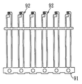
例を挙げれば、図1に示すのはサイドビュー型に用いられる従来のリードフレームモジュールであり、図2に示すのはトップビュー型に用いられる従来のリードフレームモジュールである。図示のように、サイドビュー型の複数のリードフレーム92も、トップビュー型の複数のリードフレーム92’も、一本の定位穴付きレール91、91’に沿ってそれぞれ同一の方向に突出し、互いに並列している。
For example, FIG. 1 shows a conventional lead frame module used for a side view type, and FIG. 2 shows a conventional lead frame module used for a top view type. As shown in the drawing, the plurality of side view
確かに、この一列のリードフレームから一体的に連続しているリードフレームモジュールでは、列になったリードフレーム全体に対して実装を一斉に行うことができる。しかし、図から分かるように、その金属薄板材の利用率が20%位のローレベルにあり、80%位の材料浪費があるため、この省資源の時代の流れに沿わない上、材料処理の環境汚染問題にも係わる。 Certainly, in the lead frame module that is integrally continuous from this one row of lead frames, the entire lead frame in a row can be mounted all at once. However, as can be seen from the figure, the utilization rate of the thin metal plate material is at a low level of about 20%, and there is a waste of material of about 80%. Also related to environmental pollution problems.
本考案は、発光ダイオード製造用原材料としての金属薄板材の利用率が従前より高い発光ダイオード製造用リードフレームモジュールの提供を目的とする。 An object of the present invention is to provide a lead frame module for manufacturing a light emitting diode, which has a higher utilization rate of a thin metal plate material as a raw material for manufacturing the light emitting diode.
前記目的を達成するために、本考案は、まず、同一の金属薄板材から一体的に形成される発光ダイオード製造用リードフレームモジュールにおいて、第一方向に延伸している第一のレールと、前記第一のレールに沿って、それぞれ前記第一方向と直交する第二方向に該第一のレールと接続して配置されている複数のリードフレームからなった第一のリードフレーム組と、前記第一のレールと間隔を空けて平行するように配置されている第二のレールと、前記第二のレールに沿って、それぞれ前記第二方向に該第二のレールと接続して配置されている複数のリードフレームからなった第二のリードフレーム組と、を含んでおり、且つ、前記いずれのリードフレームにも対になっている2本の電気接続リード及び該2本の電気接続リードとそれぞれ接続している一対の発光チップ実装用のリードを有しており、前記第一のリードフレーム組の電気接続リードと、前記第二のリードフレーム組の電気接続リードとは、交互に配置される、互いに連続している発光ダイオード製造用リードフレームモジュールを提供する。 In order to achieve the above object, the present invention first provides a light emitting diode manufacturing lead frame module integrally formed from the same thin metal plate, a first rail extending in a first direction, A first lead frame set comprising a plurality of lead frames arranged in connection with the first rail in a second direction orthogonal to the first direction along the first rail; A second rail arranged parallel to and spaced from one rail, and a second rail connected to the second rail in the second direction along the second rail. A second lead frame set composed of a plurality of lead frames, and two electrical connection leads paired with any of the lead frames, the two electrical connection leads, and The A pair of connected light-emitting chip mounting leads is provided, and the electrical connection leads of the first lead frame set and the electrical connection leads of the second lead frame set are alternately arranged. A lead frame module for manufacturing a light emitting diode that is continuous with each other is provided.
前記発光ダイオード用リードフレームモジュールの実施形態として、前記第一のリードフレーム組の電気接続リードと前記第二のリードフレーム組の電気接続リードとは、本毎に互い違いになっており、且つ、前記いずれの電気接続リードも、その一端が前記第一のレールと接続し、他端が前記第二のレールと接続しているものが挙げられる。 As an embodiment of the light emitting diode lead frame module, the electrical connection leads of the first lead frame set and the electrical connection leads of the second lead frame set are staggered for each book, and the Any of the electrical connection leads may have one end connected to the first rail and the other end connected to the second rail.
前記発光ダイオード製造用リードフレームモジュールの他の実施態様として、前記第一のリードフレーム組の電気接続リードと前記第二のリードフレーム組の電気接続リードとは、対毎に互い違いになっているものも挙げられる。 As another embodiment of the lead frame module for manufacturing the light emitting diode, the electrical connection leads of the first lead frame set and the electrical connection leads of the second lead frame set are staggered for each pair. Also mentioned.
そして、本考案も、同一の金属薄板材から一体的に形成されたサイドビュー型発光ダイオード製造用リードフレームモジュールにおいて、第一方向に延伸している第一のレールと、前記第一のレールに沿って、それぞれ前記第一方向と直交する第二方向に該第一のレールと接続して配置されている複数のリードフレームからなった第一のリードフレーム組と、前記第一のレールと間隔を空けて平行するように配置されている第二のレールと、前記第二のレールに沿って、それぞれ前記第二方向に該第二のレールと接続して配置されている複数のリードフレームからなった第二のリードフレーム組と、それぞれ前記第一方向に延伸しており、且つ、前記第一のレールと前記第二のレールとをその間に挟んでいる第一の定位穴付きレール及び第二の定位穴付きレールと、前記第二方向に延伸して前記第一の定位穴付きレールと前記第一のレールとを接続している複数の第三のレールと、前記第二方向に延伸して前記第二の定位穴付きレールと前記第二のレールとを接続している複数の第四のレールと、を含んでおり、且つ、前記いずれのリードフレームにも、対になっている2本の電気接続リード及び該2本の電気接続リードとそれぞれ接続している一対の発光チップ実装用のリードを有しており、前記第一のリードフレーム組の電気接続リードと、前記第二のリードフレーム組の電気接続リードとは、交互に配置される上、互いに連続しているサイドビュー型発光ダイオード製造用リードフレームモジュールを提供する。 In the lead frame module for manufacturing a side-view type light emitting diode integrally formed from the same thin metal plate, the present invention also includes a first rail extending in a first direction and the first rail. A first lead frame set comprising a plurality of lead frames arranged in connection with the first rail in a second direction orthogonal to the first direction, and a distance from the first rail. A second rail disposed parallel to the second rail, and a plurality of lead frames disposed along the second rail and connected to the second rail in the second direction, respectively. A second lead frame set, a first rail with a positioning hole extending in the first direction and sandwiching the first rail and the second rail therebetween, and two A rail with a stereotaxic hole, a plurality of third rails extending in the second direction and connecting the first rail with a stereotaxic hole and the first rail, and extending in the second direction A plurality of fourth rails connecting the second positioning hole-equipped rail and the second rail, and two pairs in any of the lead frames And a pair of light emitting chip mounting leads respectively connected to the two electrical connection leads, the electrical lead of the first lead frame set, and the second lead The lead wire module for manufacturing a side view type light emitting diode is provided which is alternately arranged with the electrical connection leads of the frame set and is continuous with each other.
前記サイドビュー型発光ダイオード製造用リードフレームモジュールの実施形態として、前記第一のリードフレーム組の電気接続リードと前記第二のリードフレーム組の電気接続リードとは、本毎に互い違いになっているものが挙げられる。 As an embodiment of the lead frame module for manufacturing the side view type light emitting diode, the electrical connection leads of the first lead frame group and the electrical connection leads of the second lead frame group are staggered for each book. Things.
そして、本考案も、また、 同一の金属薄板材から一体的に形成されたトップビュー型発光ダイオード製造用リードフレームモジュールにおいて、第一方向に延伸している第一のレールと、前記第一のレールに沿って、それぞれ前記第一方向と直交する第二方向に該第一のレールと接続して配置されている複数のリードフレームからなった第一のリードフレーム組と、前記第一のレールと間隔を空けて平行するように配置されている第二のレールと、前記第二のレールに沿って、それぞれ前記第二方向に該第二のレールと接続して配置されている複数のリードフレームからなった第二のリードフレーム組と、前記第一のレールと前記第二のレールとの間に前記第一方向に延伸している第三のレールと、を含んでおり、且つ、前記いずれのリードフレームにも、対になってそれぞれ前記第三のレールに接続されている2本の電気接続リード及び該2本の電気接続リードとそれぞれ接続している一対の発光チップ実装用のリードを有しており、前記第一のリードフレーム組の電気接続リードと、前記第二のリードフレーム組の電気接続リードとは、交互に配置されているトップビュー型発光ダイオード製造用リードフレームモジュールを提供する。 In the lead frame module for manufacturing a top-view type light emitting diode integrally formed from the same thin metal plate, the present invention also includes a first rail extending in a first direction, and the first rail. A first lead frame set comprising a plurality of lead frames arranged in connection with the first rail in a second direction perpendicular to the first direction along the rail; and the first rail And a plurality of leads arranged to be connected to the second rail in the second direction along the second rail, respectively. A second lead frame set comprising a frame, and a third rail extending in the first direction between the first rail and the second rail, and Any lead The frame also has two electric connection leads connected to the third rail in pairs and a pair of light emitting chip mounting leads connected to the two electric connection leads, respectively. The lead frame module for manufacturing a top view type light emitting diode is provided in which the electrical connection leads of the first lead frame set and the electrical connection leads of the second lead frame set are alternately arranged.
前記トップビュー型発光ダイオード製造用リードフレームモジュールの実施形態として、前記第一のリードフレーム組の電気接続リードと前記第二のリードフレーム組の電気接続リードとは、対毎に互い違いになっているものが挙げられる。 As an embodiment of the lead frame module for manufacturing the top view type light emitting diode, the electrical connection leads of the first lead frame group and the electrical connection leads of the second lead frame group are staggered for each pair. Things.
前記構造による発光ダイオード製造用リードフレームモジュールは、まず、同一の金属薄板材で打抜き加工により2列の互い違いになっているリードフレーム(即ち第一のリードフレーム組と第二のリードフレーム組)を含んでいるので、従来のモジュールよりレイアウトが密集的で、原材料としての金属薄板材の利用率も、打抜き加工の加工効率も50%位上げられる。 In the lead frame module for manufacturing a light emitting diode having the above structure, first, lead frames (that is, a first lead frame set and a second lead frame set) that are staggered in two rows by a punching process using the same thin metal plate material. As a result, the layout is denser than that of the conventional module, and the utilization rate of the metal thin plate material as the raw material and the processing efficiency of the punching process are increased by about 50%.
以下、本考案の詳細を説明する。 Details of the present invention will be described below.
図3は、本考案の第一の実施形態に係るサイドビュー型発光ダイオード製造用リードフレームモジュール1を示す平面図であり、図4は、本考案の第二の実施形態に係るトップビュー型発光ダイオード製造用リードフレームモジュール2を示す平面図である。この2つのリードフレームモジュール1、2は、いずれも、巻き取られた金属薄板材を図示のX方向(以下、第一方向と称す)に沿って引き出しながら打抜き加工により連続的に形成し、そして、先頭から適宜な長さで裁断したものである。即ち、第一の実施形態に係るサイドビュー型発光ダイオード製造用リードフレームモジュール1も、第二の実施形態に係るトップビュー型発光ダイオード製造用リードフレームモジュール2も、同一の金属薄板材から一体的に形成されたものである。 FIG. 3 is a plan view showing the lead frame module 1 for manufacturing a side view type light emitting diode according to the first embodiment of the present invention, and FIG. 4 is a top view type light emission according to the second embodiment of the present invention. It is a top view which shows the lead frame module 2 for diode manufacture. Both of these two lead frame modules 1 and 2 are continuously formed by punching while drawing the wound metal sheet material along the X direction (hereinafter referred to as the first direction) shown in the figure, and , Cut from the beginning with an appropriate length. That is, the lead frame module 1 for manufacturing the side view type light emitting diode according to the first embodiment and the lead frame module 2 for manufacturing the top view type light emitting diode according to the second embodiment are integrally formed from the same thin metal plate. It is formed.
まず、第一の実施形態に係るサイドビュー型発光ダイオード製造用リードフレームモジュール1を説明する。 First, the side view type light emitting diode manufacturing lead frame module 1 according to the first embodiment will be described.
図3に示すように、サイドビュー型発光ダイオード製造用リードフレームモジュール1は、第一のレール11と、第一のリードフレーム組17と、第二のレール12と、第二のリードフレーム組18と、第一の定位穴付きレール15及び第二の定位穴付きレール16と、複数の第三のレール13と、複数の第四のレール14とを含んでいる。
As shown in FIG. 3, the side-view type LED manufacturing lead frame module 1 includes a first rail 11, a first
前記第一のレール11も前記第二のレール12も、第一方向(X)に延伸しているが、互いに間隔を空けている。
Both the first rail 11 and the
前記第一のリードフレーム組17は、前記第一のレール11に沿って、それぞれ前記第一方向(X)と直交する第二方向(Y)に該第一のレール11と接続して配置されている複数のリードフレームからなったものである。該第一のリードフレーム組17における各リードフレームは、対になっている2本の電気接続リード171及び該2本の電気接続リード171とそれぞれ前記第一のレール11を介して接続している一対の発光チップ実装用のリード172を有する。
The first
前記第二のリードフレーム組18は、前記第二のレール12に沿って、それぞれ前記第二方向(Y)に該第二のレール12と接続して配置されている複数のリードフレームからなったものである。該第二のリードフレーム組18における各リードフレームは、対になっている2本の電気接続リード181及び該2本の電気接続リード181とそれぞれ前記第二のレール12を介して接続している一対の発光チップ実装用のリード182を有する。
The second
本実施形態における前記いずれの電気接続リード171、181も、その一端111が前記第一のレール11と接続し、他端121が前記第二のレール12と接続している。即ち、前記第一のリードフレーム組の電気接続リード171と、前記第二のリードフレーム組の電気接続リードと181とは、前記第一のレール11と前記第二のレール12を介して互いに連続している。
Each of the electrical connection leads 171 and 181 in this embodiment has one
前記第一の定位穴付きレール15及び前記第二の定位穴付きレール16は、それぞれ前記第一方向(X)に延伸しながら、前記第一のレール11と前記第二のレール12とをその間に挟んでいる。もっと詳しく説明すると、該第一の定位穴付きレール15及び該第二の定位穴付きレール16には、それぞれ複数の、前記第一方向(X)に沿って排列し、且つ、間隔を空けた定位穴151、161が形成されている。
The rails with the first
前記複数の第三のレール13は、それぞれ前記第二方向(Y)に延伸しながら互いに間隔を空けて平行する上、前記第一の定位穴付きレール15と前記第一のレール11とを接続している。そして、前記第一のリードフレーム組17における前記発光チップ実装用のリード172は、前記第一のレール11と前記第一の定位穴付きレール15との間に配置される上、対毎にその複数の第三のレール13により区切られている。
The plurality of
前記複数の第四のレール14は、それぞれ前記第二方向(Y)に延伸しながら互いに間隔を空けて平行する上、前記第二の定位穴付きレール16と前記第二のレールと12とを接続している。そして、前記第二のリードフレーム組18における前記発光チップ実装用のリード182は、前記第二のレール12と前記第二の定位穴付きレール16との間に配置される上、対毎にその複数の第四のレール14により区切られている。
The plurality of
注意すべきものは、前記第一のリードフレーム組17における前記電気接続リード171と前記第二のリードフレーム組18における前記電気接続リードと181は、本毎に互い違いになっていることである。それにより、本考案の第一の実施形態のサイドビュー型発光ダイオード製造用リードフレームモジュール1は従来のリードフレームモジュールよりレイアウトが遥かに密集的になっているので、原材料としての金属薄板材の利用率が高くなっている。 It should be noted that the electrical connection leads 171 in the first lead frame set 17 and the electrical connection leads 181 in the second lead frame set 18 are staggered for each book. As a result, the layout of the lead frame module 1 for manufacturing the side view type light emitting diode according to the first embodiment of the present invention is much denser than that of the conventional lead frame module. The rate is high.
なお、サイドビュー型発光ダイオードの実装は、図示の第一方向(X)と第二方向(Y)とから定義された平面を基準とすれば、該平面に垂直になる方向から、前記リードフレームモジュール1上のあらゆるリードフレームの発光チップ実装用のリード172、182に対して同時に行うので、本考案の第一の実施形態のリードフレームモジュール1を実装前に前もってそれぞれ1列のリードフレーム(即ち第一のリードフレーム組17または第二のリードフレーム組18)を有する2部分に分断する必要がなく、そのまま従来の設備で行うことができる。
The side-view type light emitting diode is mounted on the lead frame from a direction perpendicular to the plane defined from the first direction (X) and the second direction (Y) shown in the drawing. Since all the lead frames on the module 1 are mounted simultaneously on the
次に、本考案の第二の実施形態に係るトップビュー型発光ダイオード製造用リードフレームモジュール2を説明する。 Next, a lead frame module 2 for manufacturing a top view type light emitting diode according to a second embodiment of the present invention will be described.
図4に示すように、トップビュー型発光ダイオード製造用リードフレームモジュール2は、第一のレール21と、第一のリードフレーム組25と、第二のレール22と、第二のリードフレーム組26と、第三のレール20とを含んでいる。
As shown in FIG. 4, the top view type light emitting diode manufacturing lead frame module 2 includes a first rail 21, a first lead frame set 25, a
前記第一のレール21も前記第二のレール22も、第一方向(X)に延伸しているが、互いに間隔を空けている。
Both the first rail 21 and the
前記第一のリードフレーム組25は、前記第一のレール21に沿って、それぞれ前記第一方向(X)と直交する第二方向(Y)に該第一のレール21と接続して配置されている複数のリードフレームからなったものである。該第一のリードフレーム組25における各リードフレームは、対になっている2本の電気接続リード251及び該2本の電気接続リード251とそれぞれ前記第一のレール21を介して接続している一対の発光チップ実装用のリード252を有する。前記第一のリードフレーム組25における各電気接続リード251は、第一のレール21と離れた第一の先端部230を有し、また、前記第一のリードフレーム組25におけるそれぞれ対になっている電気接続リード251の第一の先端部230は、更に、第一の定位穴付き部材23を介して連続している。
The first lead frame set 25 is disposed along the first rail 21 so as to be connected to the first rail 21 in a second direction (Y) orthogonal to the first direction (X). It consists of a plurality of lead frames. Each lead frame in the first lead frame set 25 is connected to a pair of two electrical connection leads 251 and the two electrical connection leads 251 via the first rail 21. A pair of light-emitting chip mounting leads 252 is provided. Each
前記第二のリードフレーム組26は、前記第二のレール22に沿って、それぞれ前記第一方向(X)と直交する第二方向(Y)に該第二のレール22と接続して配置されている複数のリードフレームからなったものである。該第二のリードフレーム組26における各リードフレームは、対になっている2本の電気接続リード261及び該2本の電気接続リード261とそれぞれ前記第二のレール22を介して接続している一対の発光チップ実装用のリード262を有する。前記第二のリードフレーム組26における各電気接続リード261は、第二のレール22と離れた第二の先端部240を有し、また、前記第二のリードフレーム組26におけるそれぞれ対になっている電気接続リード261の第二の先端部240は、更に、第二の定位穴付き部材24を介して連続している。
The second lead frame set 26 is disposed along the
前記第三のレール20は、前記第一の定位穴付き部材23と前記第二の定位穴付き部材24とを両側にするように前記第一方向(X)に延伸して、前記第一のリードフレーム組25の各電気接続リード251と前記第二のリードフレーム組26の各電気接続リード261とを接続している。また、前記第一の定位穴付き部材23も前記第二の定位穴付き部材24も、前記第一のレール21と前記第二のレール22との間に配置されている。
The
注意すべきものは、前記第一のリードフレーム組25における前記電気接続リード251と前記第二のリードフレーム組26における前記電気接続リードと261とは、対毎に互い違いになっていることにある。それにより、本考案の第二の実施形態に係るトップビュー型発光ダイオード製造用リードフレームモジュール2は従来のリードフレームモジュールよりレイアウトが遥かに密集的になっているので、原材料としての金属薄板材の利用率が高くなっている。 It should be noted that the electrical connection leads 251 in the first lead frame set 25 and the electrical connection leads 261 in the second lead frame set 26 are staggered in pairs. Accordingly, the top view type light emitting diode manufacturing lead frame module 2 according to the second embodiment of the present invention has a layout much denser than that of the conventional lead frame module. The utilization rate is high.
また、トップビュー型発光ダイオードの実装は、図示の第一方向(X)と第二方向(Y)とから定義された平面を基準とすれば、前記第二方向(Y)からリードフレームの発光チップ実装用のリード252、262の端面に対して行うので、前記リードフレームモジュール2を実装前に前もってそれぞれ1列のリードフレーム(即ち第一のリードフレーム組25または第二のリードフレーム組26)を有する2部分に分断してから、始めて従来の設備で行うことができる。
In addition, when mounting the top-view type light emitting diode, the lead frame emits light from the second direction (Y) when the plane defined by the first direction (X) and the second direction (Y) shown in the drawing is used as a reference. Since it is performed on the end surfaces of the
ちなみに、前記第一の実施形態のサイドビュー型発光ダイオード製造用リードフレームモジュール1の第一のリードフレーム組17及び第二のリードフレーム組18も、第二の実施形態のように配置されてもよい。 Incidentally, the first lead frame set 17 and the second lead frame set 18 of the side view type light emitting diode manufacturing lead frame module 1 of the first embodiment may also be arranged as in the second embodiment. Good.
叙上のように、本考案の発光ダイオード製造用リードフレームモジュールは、原材料としての金属薄板材の利用率も、打抜き加工の加工効率も大幅に上げられるので、コストの面からみてとても実用的である。 As mentioned above, the lead frame module for manufacturing a light emitting diode according to the present invention is very practical from the viewpoint of cost because the utilization rate of the metal thin plate material as the raw material and the processing efficiency of the punching process are greatly increased. is there.
以上、本考案をいくつかの好ましい実施形態によって記述したが、同業者ならば、本考案の実用新案登録請求の範囲に開示した範疇及び思想から外れずに、多くの変形及び修正がなされ得ることがわかるはずである。 Although the present invention has been described in terms of several preferred embodiments, many variations and modifications can be made by those skilled in the art without departing from the scope and spirit disclosed in the claims of the utility model registration of the present invention. Should be understood.
1 サイドビュー型発光ダイオード製造用リードフレームモジュール
11 第一のレール
111 電気接続リードと第一のレールとの連接端
12 第二のレール
121 電気接続リードと第二のレールとの連接端
13 第三のレール
14 第四のレール
15 第一の定位穴付きレール
151 定位穴
16 第二の定位穴付きレール
161 定位穴
17 第一のリードフレーム組
171 電気接続リード
172 発光チップ実装用のリード
18 第二のリードフレーム組
181 電気接続リード
182 発光チップ実装用のリード
2 トップビュー型発光ダイオード製造用リードフレームモジュール
20 第三のレール
21 第一のレール
22 第二のレール
23 第一の定位穴付き部材
230 第一の先端部
24 第二の定位穴付き部材
240 第二の先端部
25 第一のリードフレーム組
251 電気接続リード
252 発光チップ実装用のリード
26 第二のリードフレーム組
261 電気接続リード
262 発光チップ実装用のリード
91 サイドビュー型の定位穴付きレール
92 サイドビュー型のリードフレーム
91’ トップビュー型の定位穴付きレール
92’ トップビュー型のリードフレーム
DESCRIPTION OF SYMBOLS 1 Lead frame module for side view type light emitting diode manufacture 11
Claims (15)
第一方向に延伸している第一のレールと、
前記第一のレールに沿って、それぞれ前記第一方向と直交する第二方向に該第一のレールと接続して配置されている複数のリードフレームからなった第一のリードフレーム組と、
前記第一のレールと間隔を空けて平行するように配置されている第二のレールと、
前記第二のレールに沿って、それぞれ前記第二方向に該第二のレールと接続して配置されている複数のリードフレームからなった第二のリードフレーム組と、を含んでおり、
且つ、前記いずれのリードフレームにも対になっている2本の電気接続リード及び該2本の電気接続リードとそれぞれ接続している一対の発光チップ実装用のリードを有しており、
前記第一のリードフレーム組の電気接続リードと、前記第二のリードフレーム組の電気接続リードとは、交互に配置される上、互いに連続していることを特徴とする発光ダイオード製造用リードフレームモジュール。 In the lead frame module for manufacturing a light emitting diode integrally formed from the same metal thin plate material,
A first rail extending in a first direction;
A first lead frame set comprising a plurality of lead frames arranged in connection with the first rail in a second direction orthogonal to the first direction, respectively, along the first rail;
A second rail arranged to be parallel to and spaced from the first rail;
A second lead frame set comprising a plurality of lead frames arranged in connection with the second rail in the second direction along the second rail, respectively.
And having two electrical connection leads paired with any of the lead frames and a pair of light emitting chip mounting leads respectively connected to the two electrical connection leads,
The lead frame for manufacturing a light emitting diode, wherein the electrical connection leads of the first lead frame group and the electrical connection leads of the second lead frame group are alternately arranged and are continuous with each other module.
且つ、前記いずれの電気接続リードも、その一端が前記第一のレールと接続し、他端が前記第二のレールと接続していることを特徴とする請求項1に記載の発光ダイオード製造用リードフレームモジュール。 The electrical connection leads of the first lead frame set and the electrical connection leads of the second lead frame set are staggered for each book,
2. The light emitting diode manufacturing method according to claim 1, wherein one of the electrical connection leads has one end connected to the first rail and the other end connected to the second rail. Lead frame module.
前記第二方向に延伸して前記第一の定位穴付きレールと前記第一のレールとを接続している複数の第三のレールと、
前記第二方向に延伸して前記第二の定位穴付きレールと前記第二のレールとを接続している複数の第四のレールと、が更に形成されており、
且つ、前記第一のリードフレーム組の発光チップ実装用のリードは、前記第一のレールと前記第一の定位穴付きレールとの間に配置されており、
前記第二のリードフレーム組の発光チップ実装用のリードは、前記第二のレールと前記第二の定位穴付きレールとの間に配置されていることを特徴とする請求項2に記載の発光ダイオード製造用リードフレームモジュール。 A rail with a first localization hole and a rail with a second localization hole, each extending in the first direction and sandwiching the first rail and the second rail therebetween,
A plurality of third rails extending in the second direction and connecting the first rail with a positioning hole and the first rail;
A plurality of fourth rails extending in the second direction and connecting the second rail with a stereotaxic hole and the second rail are further formed;
And the lead for mounting the light emitting chip of the first lead frame set is disposed between the first rail and the rail with the first positioning hole,
The light emitting chip mounting lead of the second lead frame set is disposed between the second rail and the second rail with a stereotaxic hole. Lead frame module for diode manufacturing.
前記第二のリードフレーム組の発光チップ実装用のリードは、対毎に前記複数の第四のレールに区切られていることを特徴とする請求項3に記載の発光ダイオード製造用リードフレームモジュール。 The lead for mounting the light emitting chip of the first lead frame set is divided into a plurality of third rails for each pair,
4. The lead frame module for manufacturing a light emitting diode according to claim 3, wherein the lead for mounting the light emitting chip of the second lead frame set is partitioned into the plurality of fourth rails for each pair.
前記第二のリードフレーム組における各電気接続リードは、第二のレールと離れた第二の先端部を有し、また、前記第二のリードフレーム組におけるそれぞれ対になっている電気接続リードの第二の先端部は、更に、第二の定位穴付き部材を介して連続していることを特徴とする請求項5に記載の発光ダイオード製造用リードフレームモジュール。 Each electrical connection lead in the first lead frame set has a first tip portion separated from the first rail, and each pair of electrical connection leads in the first lead frame set. The first tip is further continuous via the first stereotactic hole member,
Each electrical connection lead in the second lead frame set has a second tip portion separated from the second rail, and each pair of electrical connection leads in the second lead frame set 6. The lead frame module for manufacturing a light emitting diode according to claim 5, wherein the second tip portion is further continuous via a second member with a stereotaxic hole.
第一方向に延伸している第一のレールと、
前記第一のレールに沿って、それぞれ前記第一方向と直交する第二方向に該第一のレールと接続して配置されている複数のリードフレームからなった第一のリードフレーム組と、
前記第一のレールと間隔を空けて平行するように配置されている第二のレールと、
前記第二のレールに沿って、それぞれ前記第二方向に該第二のレールと接続して配置されている複数のリードフレームからなった第二のリードフレーム組と、
それぞれ前記第一方向に延伸しており、且つ、前記第一のレールと前記第二のレールとをその間に挟んでいる第一の定位穴付きレール及び第二の定位穴付きレールと、
前記第二方向に延伸して前記第一の定位穴付きレールと前記第一のレールとを接続している複数の第三のレールと、
前記第二方向に延伸して前記第二の定位穴付きレールと前記第二のレールとを接続している複数の第四のレールと、を含んでおり、
且つ、前記いずれのリードフレームにも、対になっている2本の電気接続リード及び該2本の電気接続リードとそれぞれ接続している一対の発光チップ実装用のリードを有しており、
前記第一のリードフレーム組の電気接続リードと、前記第二のリードフレーム組の電気接続リードとは、交互に配置される上、互いに連続していることを特徴とするサイドビュー型発光ダイオード製造用リードフレームモジュール。 In the lead frame module for manufacturing a side view type light emitting diode integrally formed from the same thin metal plate material,
A first rail extending in a first direction;
A first lead frame set comprising a plurality of lead frames arranged in connection with the first rail in a second direction orthogonal to the first direction, respectively, along the first rail;
A second rail arranged to be parallel to and spaced from the first rail;
A second lead frame set consisting of a plurality of lead frames disposed in connection with the second rail in the second direction along the second rail;
A rail with a first localization hole and a rail with a second localization hole, each extending in the first direction and sandwiching the first rail and the second rail therebetween,
A plurality of third rails extending in the second direction and connecting the first rail with a positioning hole and the first rail;
A plurality of fourth rails extending in the second direction and connecting the second positioning hole-equipped rail and the second rail;
Each of the lead frames has a pair of two electrical connection leads and a pair of light emitting chip mounting leads connected to the two electrical connection leads,
The electrical connection leads of the first lead frame group and the electrical connection leads of the second lead frame group are alternately arranged and are continuous with each other. Lead frame module.
且つ、前記いずれの電気接続リードも、その一端が前記第一のレールと接続し、他端が前記第二のレールと接続していることを特徴とする請求項9に記載のサイドビュー型発光ダイオード製造用リードフレームモジュール。 The electrical connection leads of the first lead frame set and the electrical connection leads of the second lead frame set are staggered for each book,
10. The side-view type light emitting device according to claim 9, wherein each of the electrical connection leads has one end connected to the first rail and the other end connected to the second rail. Lead frame module for diode manufacturing.
前記第二のリードフレーム組の発光チップ実装用のリードは、前記第二のレールと前記第二の定位穴付きレールとの間に配置される上、対毎に前記複数の第四のレールに区切られていることを特徴とする請求項10に記載のサイドビュー型発光ダイオード製造用リードフレームモジュール。 The lead for mounting the light emitting chip of the first lead frame set is disposed between the first rail and the rail with the first positioning hole, and is connected to the plurality of third rails for each pair. Is delimited,
The leads for mounting the light emitting chip of the second lead frame set are disposed between the second rail and the rail with the second positioning hole, and are arranged on the plurality of fourth rails in pairs. The lead frame module for manufacturing a side view type light emitting diode according to claim 10, wherein the lead frame module is divided.
第一方向に延伸している第一のレールと、
前記第一のレールに沿って、それぞれ前記第一方向と直交する第二方向に該第一のレールと接続して配置されている複数のリードフレームからなった第一のリードフレーム組と、
前記第一のレールと間隔を空けて平行するように配置されている第二のレールと、
前記第二のレールに沿って、それぞれ前記第二方向に該第二のレールと接続して配置されている複数のリードフレームからなった第二のリードフレーム組と、
前記第一のレールと前記第二のレールとの間に前記第一方向に延伸している第三のレールと、を含んでおり、
且つ、前記いずれのリードフレームにも、対になってそれぞれ前記第三のレールに接続されている2本の電気接続リード及び該2本の電気接続リードとそれぞれ接続している一対の発光チップ実装用のリードを有しており、
前記第一のリードフレーム組の電気接続リードと、前記第二のリードフレーム組の電気接続リードとは、交互に配置されていることを特徴とするトップビュー型発光ダイオード製造用リードフレームモジュール。 In the lead frame module for manufacturing the top view type light emitting diode integrally formed from the same metal thin plate material,
A first rail extending in a first direction;
A first lead frame set comprising a plurality of lead frames arranged in connection with the first rail in a second direction orthogonal to the first direction, respectively, along the first rail;
A second rail arranged to be parallel to and spaced from the first rail;
A second lead frame set consisting of a plurality of lead frames disposed in connection with the second rail in the second direction along the second rail;
A third rail extending in the first direction between the first rail and the second rail;
In addition, each of the lead frames has a pair of two electrical connection leads connected to the third rail, and a pair of light emitting chips connected to the two electrical connection leads, respectively. Have leads for
The lead frame module for manufacturing a top view type light emitting diode, wherein the electrical connection leads of the first lead frame set and the electrical connection leads of the second lead frame set are alternately arranged.
前記第二のリードフレーム組における各電気接続リードは、第二のレールと離れた第二の先端部を有し、また、前記第二のリードフレーム組におけるそれぞれ対になっている電気接続リードの第二の先端部は、更に、第二の定位穴付き部材を介して連続していることを特徴とする請求項13に記載の発光ダイオード製造用リードフレームモジュール。 Each electrical connection lead in the first lead frame set has a first tip portion separated from the first rail, and each pair of electrical connection leads in the first lead frame set. The first tip is further continuous via the first stereotactic hole member,
Each electrical connection lead in the second lead frame set has a second tip portion separated from the second rail, and each pair of electrical connection leads in the second lead frame set 14. The lead frame module for manufacturing a light emitting diode according to claim 13, wherein the second tip portion is further continuous via a second member with a stereotaxic hole.
前記第三のレールは、前記第一の定位穴付き部材と前記第二の定位穴付き部材とを両側にするように配置されていることを特徴とする請求項14に記載のトップビュー型発光ダイオード製造用リードフレームモジュール。 The first stereotactic hole member and the second stereotactic hole member are both disposed between the first rail and the second rail,
15. The top-view type light emitting device according to claim 14, wherein the third rail is disposed so that the first positioning hole-attached member and the second positioning hole-attached member are on both sides. Lead frame module for diode manufacturing.
Applications Claiming Priority (1)
| Application Number | Priority Date | Filing Date | Title |
|---|---|---|---|
| CN2008100270880A CN101546796B (en) | 2008-03-25 | 2008-03-25 | LED conducting wire bracket |
Publications (1)
| Publication Number | Publication Date |
|---|---|
| JP3146899U true JP3146899U (en) | 2008-12-04 |
Family
ID=41116901
Family Applications (1)
| Application Number | Title | Priority Date | Filing Date |
|---|---|---|---|
| JP2008006731U Expired - Lifetime JP3146899U (en) | 2008-03-25 | 2008-09-24 | Lead frame module for light emitting diode manufacturing |
Country Status (3)
| Country | Link |
|---|---|
| US (1) | US7688599B2 (en) |
| JP (1) | JP3146899U (en) |
| CN (1) | CN101546796B (en) |
Cited By (1)
| Publication number | Priority date | Publication date | Assignee | Title |
|---|---|---|---|---|
| KR101146506B1 (en) * | 2009-07-24 | 2012-05-25 | 브라이트 엘이디 엘렉트로닉 코퍼레이션 | Light emitting diode lighting module and method for making the same |
Families Citing this family (2)
| Publication number | Priority date | Publication date | Assignee | Title |
|---|---|---|---|---|
| JP5875848B2 (en) * | 2011-12-16 | 2016-03-02 | 株式会社東芝 | Photocoupler manufacturing method and photocoupler lead frame sheet |
| CN102683554B (en) * | 2012-05-29 | 2016-07-06 | 新疆紫晶光电技术有限公司 | LED light source module and chip measurability method for packing thereof based on KGD design |
Family Cites Families (8)
| Publication number | Priority date | Publication date | Assignee | Title |
|---|---|---|---|---|
| US4129682A (en) * | 1977-11-16 | 1978-12-12 | Monsanto Company | High density led lead frame |
| US5150194A (en) * | 1991-04-24 | 1992-09-22 | Micron Technology, Inc. | Anti-bow zip lead frame design |
| JP3096824B2 (en) * | 1992-04-17 | 2000-10-10 | ローム株式会社 | LED manufacturing frame and LED manufacturing method using the same |
| EP0793853A1 (en) * | 1995-06-30 | 1997-09-10 | Koninklijke Philips Electronics N.V. | Surface-mountable electrical component |
| US6268643B1 (en) * | 1997-12-22 | 2001-07-31 | Texas Instruments Incorporated | Lead frame device for delivering electrical power to a semiconductor die |
| TW434756B (en) * | 1998-06-01 | 2001-05-16 | Hitachi Ltd | Semiconductor device and its manufacturing method |
| US7132734B2 (en) * | 2003-01-06 | 2006-11-07 | Micron Technology, Inc. | Microelectronic component assemblies and microelectronic component lead frame structures |
| US7183485B2 (en) * | 2003-03-11 | 2007-02-27 | Micron Technology, Inc. | Microelectronic component assemblies having lead frames adapted to reduce package bow |
-
2008
- 2008-03-25 CN CN2008100270880A patent/CN101546796B/en active Active
- 2008-08-26 US US12/230,194 patent/US7688599B2/en active Active
- 2008-09-24 JP JP2008006731U patent/JP3146899U/en not_active Expired - Lifetime
Cited By (1)
| Publication number | Priority date | Publication date | Assignee | Title |
|---|---|---|---|---|
| KR101146506B1 (en) * | 2009-07-24 | 2012-05-25 | 브라이트 엘이디 엘렉트로닉 코퍼레이션 | Light emitting diode lighting module and method for making the same |
Also Published As
| Publication number | Publication date |
|---|---|
| US20090244875A1 (en) | 2009-10-01 |
| CN101546796B (en) | 2012-01-11 |
| US7688599B2 (en) | 2010-03-30 |
| CN101546796A (en) | 2009-09-30 |
Similar Documents
| Publication | Publication Date | Title |
|---|---|---|
| CN102135244B (en) | Multiple light emitting diode light source lamps | |
| RU2596800C2 (en) | Method of manufacturing of led matrix and device containing led matrix | |
| KR101233121B1 (en) | method for manufacturing light emitting diode array substrate with surface type and the light emitting diode array substrate thereby | |
| TWI415309B (en) | Preform Molded Polycrystalline Bearing Modules with Lead Frame Type | |
| JP3146899U (en) | Lead frame module for light emitting diode manufacturing | |
| US9374909B2 (en) | Method of manufacturing LED module | |
| CN104412034A (en) | Electrode module for LED lamp | |
| JP2014204078A (en) | Flexible printed wiring board, lighting fixture, and method of manufacturing the same | |
| KR101300577B1 (en) | Led lamp for vehicle and the method thereof | |
| KR101321812B1 (en) | method for manufacturing substrate for light emitting device mounted driving and power supply circuit together and the substrate thereby | |
| KR20140038881A (en) | Light emitting diode module and method for manufacturing the same | |
| CN103682019B (en) | Light-emitting diode and manufacturing method thereof | |
| JP6104616B2 (en) | LED module | |
| KR20100082394A (en) | Pcb block and led module comprising the same | |
| JP2011003595A (en) | Mounting wiring board for lighting, lighting device, and lighting fixture | |
| KR101764344B1 (en) | method for manufacturing substrate for light emitting device mounted driving and power supply circuit together and the substrate thereby | |
| CN103047575A (en) | Light-emitting diode light bar and manufacture method thereof | |
| KR20110077247A (en) | LED lighting device with easy connection | |
| KR102186812B1 (en) | Led pcb | |
| TW201034146A (en) | Leadframe, assembly of leadframe and substrate and LED module | |
| KR100646630B1 (en) | Manufacturing method of printed circuit board for light emitting diode and printed circuit board for light emitting diode using same | |
| KR101394478B1 (en) | substrate for light emitting device | |
| JP2014011444A (en) | Printed board and light-emitting device | |
| KR102249553B1 (en) | LED PCB and method for manufacturing the same | |
| CN102883527A (en) | Flexible circuit board for LED and manufacturing method of flexible circuit board |
Legal Events
| Date | Code | Title | Description |
|---|---|---|---|
| R150 | Certificate of patent or registration of utility model |
Free format text: JAPANESE INTERMEDIATE CODE: R150 |
|
| FPAY | Renewal fee payment (event date is renewal date of database) |
Free format text: PAYMENT UNTIL: 20111112 Year of fee payment: 3 |
|
| FPAY | Renewal fee payment (event date is renewal date of database) |
Free format text: PAYMENT UNTIL: 20111112 Year of fee payment: 3 |
|
| FPAY | Renewal fee payment (event date is renewal date of database) |
Free format text: PAYMENT UNTIL: 20121112 Year of fee payment: 4 |
|
| FPAY | Renewal fee payment (event date is renewal date of database) |
Free format text: PAYMENT UNTIL: 20121112 Year of fee payment: 4 |
|
| FPAY | Renewal fee payment (event date is renewal date of database) |
Free format text: PAYMENT UNTIL: 20131112 Year of fee payment: 5 |
|
| S533 | Written request for registration of change of name |
Free format text: JAPANESE INTERMEDIATE CODE: R323533 |
|
| R350 | Written notification of registration of transfer |
Free format text: JAPANESE INTERMEDIATE CODE: R350 |
|
| R250 | Receipt of annual fees |
Free format text: JAPANESE INTERMEDIATE CODE: R250 |
|
| R250 | Receipt of annual fees |
Free format text: JAPANESE INTERMEDIATE CODE: R250 |
|
| R250 | Receipt of annual fees |
Free format text: JAPANESE INTERMEDIATE CODE: R250 |
|
| R250 | Receipt of annual fees |
Free format text: JAPANESE INTERMEDIATE CODE: R250 |
|
| EXPY | Cancellation because of completion of term |