JP3246110U - Fasteners and bobbins - Google Patents
Fasteners and bobbins Download PDFInfo
- Publication number
- JP3246110U JP3246110U JP2024000186U JP2024000186U JP3246110U JP 3246110 U JP3246110 U JP 3246110U JP 2024000186 U JP2024000186 U JP 2024000186U JP 2024000186 U JP2024000186 U JP 2024000186U JP 3246110 U JP3246110 U JP 3246110U
- Authority
- JP
- Japan
- Prior art keywords
- surface portion
- claw
- bobbin
- outer circumferential
- circumferential surface
- Prior art date
- Legal status (The legal status is an assumption and is not a legal conclusion. Google has not performed a legal analysis and makes no representation as to the accuracy of the status listed.)
- Active
Links
Images


Landscapes
- Winding Filamentary Materials (AREA)
Abstract
【課題】シャフトの回転による留め具の変形が抑制された留め具、または当該留め具を含むボビンを提供する。【解決手段】留め具1は、ボビン100において当該ボビン100の軸方向の端部に取付けられる。ボビン100とは、長尺の被巻取物が巻き取られる部品である。留め具1には、ボビン100を回転させるためのシャフト200が挿入される穴部22が形成されている。留め具1は、紙製の本体部20と、金属製の補強部40と、を有する。本体部20は、軸方向におけるボビン100の端部に固定される。また、本体部20は、軸方向に貫通する穴部22を有する。補強部40は、本体部20に固定され、穴部22を画成する内壁24を覆う。【選択図】図2The present invention provides a fastener in which deformation of the fastener due to rotation of a shaft is suppressed, or a bobbin including the fastener. A fastener 1 is attached to an axial end of a bobbin 100. The bobbin 100 is a component on which a long object is wound. The fastener 1 is formed with a hole 22 into which a shaft 200 for rotating the bobbin 100 is inserted. The fastener 1 includes a main body portion 20 made of paper and a reinforcing portion 40 made of metal. The main body portion 20 is fixed to an end of the bobbin 100 in the axial direction. Further, the main body portion 20 has a hole portion 22 that penetrates in the axial direction. The reinforcing portion 40 is fixed to the main body portion 20 and covers the inner wall 24 defining the hole portion 22. [Selection diagram] Figure 2
Description
本考案は、留め具及びボビンに関する。 The present invention relates to a fastener and a bobbin.
長尺物を巻き取る軸部材としてボビンが用いられる場合があり、ボビンの軸方向において当該ボビンの両端部には留め具が取付けられる場合がある。この種の技術に関し、下記特許文献1には、両端に中央部プラグ(4,5)が取付けられるドラム(ボビン)が開示されている。中央部プラグ(4,5)およびドラムは木材チップ材または紙からなることが記載されている。
A bobbin is sometimes used as a shaft member for winding up a long object, and fasteners are sometimes attached to both ends of the bobbin in the axial direction of the bobbin. Regarding this type of technology,
中央部プラグ(4,5)には、長尺物を巻き取るまたは長尺物を巻き解くための旋回装置を受け入れるための中央穴部(10)が形成されている。旋回装置におけるシャフトが当該中央穴部(10)に挿入され、シャフトの回転に伴って留め具およびボビンが回転することで長尺物をボビンに巻き取ること、または長尺物をボビンから巻き解くことができる。しかしながら、シャフトとともに留め具およびボビンが回転する際、回転するシャフトから留め具(特に中央穴部(10)の近傍)に外力が加わり、留め具が変形するという問題が生じる。 The central plugs (4, 5) are formed with a central hole (10) for receiving a pivoting device for winding up or unwinding elongated objects. The shaft of the turning device is inserted into the central hole (10), and the fastener and bobbin rotate as the shaft rotates, thereby winding a long object onto the bobbin or unwinding the long object from the bobbin. be able to. However, when the fastener and bobbin rotate together with the shaft, an external force is applied from the rotating shaft to the fastener (particularly in the vicinity of the central hole (10)), causing a problem that the fastener is deformed.
本考案は上述のような課題に鑑みてなされたものであり、シャフトの回転による留め具の変形が抑制された留め具、または当該留め具を含むボビンを提供するものである。 The present invention has been made in view of the above-mentioned problems, and provides a fastener in which deformation of the fastener due to shaft rotation is suppressed, or a bobbin including the fastener.
本考案の留め具は、長尺の被巻取物が巻き取られるボビンにおいて当該ボビンの軸方向の端部に取付けられ、前記ボビンを回転させるためのシャフトが挿入される穴部が形成された留め具であって、前記軸方向における前記ボビンの端部に固定され、前記軸方向に貫通する前記穴部を有する紙製の本体部と、前記本体部に固定され、前記穴部を画成する内壁を覆う金属製の補強部と、を有することを特徴とする。 The fastener of the present invention is attached to an axial end of a bobbin on which a long object is wound, and has a hole into which a shaft for rotating the bobbin is inserted. The fastener includes a paper main body fixed to an end of the bobbin in the axial direction and having the hole passing through the axial direction, and a paper main body fixed to the main body and defining the hole. A metal reinforcing part that covers the inner wall.
本考案のボビンは、長尺の被巻取物が巻き取られるボビンであって、前記被巻取物が巻き付けられて軸方向に延在するボビン本体と、前記ボビン本体の端部に取付けられ、前記ボビン本体を回転させるためのシャフトが挿入される穴部が形成された留め具と、を有し、前記留め具は、前記軸方向における前記ボビン本体の端部に固定され、前記軸方向に貫通する前記穴部を有する紙製の本体部と、前記本体部に固定され、前記穴部を画成する内壁を覆う金属製の補強部と、を備えることを特徴とする。 The bobbin of the present invention is a bobbin on which a long material to be wound is wound, and includes a bobbin body around which the material to be wound is wound and extends in the axial direction, and a bobbin body attached to an end of the bobbin body. , a fastener in which a hole is formed into which a shaft for rotating the bobbin body is inserted; the fastener is fixed to an end of the bobbin body in the axial direction, and the fastener is fixed to an end of the bobbin body in the axial direction; The invention is characterized by comprising a main body made of paper and having the hole penetrating through the body, and a reinforcing part made of metal that is fixed to the main body and covers an inner wall defining the hole.
本考案の留め具によれば、留め具の穴部を画成する内壁が金属製の補強部により覆われていることで、留め具の穴部を画成する内壁に向けて回転するシャフトによる外力がかかった場合でも補強部が当該外力を受ける。
これにより、シャフトの回転による留め具の変形が抑制された留め具またはボビンが提供できる。
According to the fastener of the present invention, since the inner wall defining the hole of the fastener is covered with the metal reinforcing portion, the shaft rotating toward the inner wall defining the hole of the fastener can be Even when an external force is applied, the reinforcing portion receives the external force.
Thereby, it is possible to provide a fastener or bobbin in which deformation of the fastener due to rotation of the shaft is suppressed.
本考案の留め具およびボビンの各種の構成要素は、個々に独立した存在である必要はなく、複数の構成要素が一個の部材として形成されていること、一つの構成要素が複数の部材で形成されていること、ある構成要素が他の構成要素の一部であること、ある構成要素の一部と他の構成要素の一部とが重複していること、等を許容する。 The various components of the fastener and bobbin of the present invention do not need to exist independently, but multiple components may be formed as a single member, or one component may be formed from multiple members. It is allowed that a certain component is a part of another component, that a part of a certain component overlaps with a part of another component, etc.
以下、本考案の実施形態を図面に基づいて説明する。尚、各図面において、対応する構成要素には共通の符号を付し、重複する説明は適宜省略する。
また、本考案でいう平面とは、平面を目標として物理的に形成した形状を意味しており、当然ながら幾何学的に完全な平面であることは要しない。
Hereinafter, embodiments of the present invention will be described based on the drawings. Note that in each drawing, corresponding components are denoted by common reference numerals, and overlapping explanations will be omitted as appropriate.
Furthermore, the term "plane" as used in the present invention refers to a shape physically formed with a plane as a target, and it goes without saying that it does not need to be a geometrically perfect plane.
<第一実施形態>
(留め具)
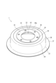
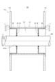
図1は、本考案の第一の実施形態にかかる留め具1の一例を示す斜視図である。また、図2は、留め具1が取付けられたボビン100の断面図である。
<First embodiment>
(Fastener)
FIG. 1 is a perspective view showing an example of a
はじめに、本実施形態の留め具1の概要について説明する。
図2に図示されるように、留め具1は、ボビン100において当該ボビン100の軸方向の端部に取付けられる。ボビン100とは、長尺の被巻取物が巻き取られる部品である。留め具1には、ボビン100を回転させるためのシャフト200が挿入される穴部22が形成されている。
図1に図示されるように、留め具1は、紙製の本体部20と、金属製の補強部40と、を有する。本体部20は、軸方向におけるボビン100の端部に固定される。また、本体部20は、軸方向に貫通する穴部22を有する。補強部40は、本体部20に固定され、穴部22を画成する内壁24を覆う。
被巻取物をボビン100に巻き取る際、または被巻取物がボビン100から巻き解かれる際、ボビン100の荷重(被巻取物の自重も含む)がシャフト200にかかることで、穴部22が変形する可能性がある。ボビン100の荷重がシャフト200にかかることで、留め具1における穴部22の周囲の一部に向けて、シャフト200からの外力がかかるためである。
上記構成によれば、留め具1の穴部22を画成する内壁24が金属製の補強部40により覆われている。これにより、留め具1における穴部22の周囲の一部に向けて、シャフト200からの外力がかかった場合でも、当該外力を紙製の内壁24が受けることなく、当該外力を金属製で変形しにくい補強部40が受けることができる。
これにより、シャフト200の回転による留め具1の変形が抑制された留め具1またはボビン100が提供できる。
First, an overview of the
As illustrated in FIG. 2, the
As illustrated in FIG. 1, the
When winding a material to be wound onto the
According to the above configuration, the
Thereby, it is possible to provide the
次に、本実施形態の留め具1について詳細に説明する。
図2に図示されるように、ボビン100とは、上述したように長尺の被巻取物が巻き取られる部品である。ここで被巻取物とは、例えば、互いに連結して長尺に連なる部品が挙げられる。より具体的には、例えば、互いに連結して長尺に連なる個包装の乾燥剤や、個包装の部材が挙げられる。
ボビン100は、ボビン本体110を有する。ボビン本体110は、被巻取物が巻き取られる巻回部111および、ボビン100の軸方向の両端に配置される一対の鍔部112,112を有する。巻回部111は中空で、巻回部111の内部にはボビン100の軸方向においてボビン本体110を貫通する中空部113が存在する。
本実施形態に代えて、ボビン本体110は中実に形成されていてもよい。この場合も、穴部22を有する一対の留め具1がボビン本体110の両端にそれぞれに取付けられる。
ここで、ボビン100の軸方向とは、被巻取物が巻回されるときの巻軸の延在する方向であり、図2において一点鎖線が示す方向(左右方向)である。以下において、ボビン100の軸方向を単に軸方向と呼ぶ場合がある。また、留め具1単体についても軸方向を言及する場合がある。この場合、留め具1における軸方向とは、留め具1をボビン100に取付けた場合におけるボビン100の軸方向にあたる方向である。より具体的には、後述する穴部22の貫通方向(図5における一点鎖線で示す方向)が、留め具1単体における軸方向である。
ボビン本体110は、巻回部111および鍔部112を有する部材をいい、留め具1を含まない部材をいう。以下において、ボビン本体110をボビン100と呼ぶことがあり、留め具1が取付けられたボビン本体110をボビン100と呼ぶこともある。
Next, the
As illustrated in FIG. 2, the
The
Instead of this embodiment, the
Here, the axial direction of the
The
留め具1とは、ボビン100(ボビン本体110)の端部(軸方向における端部)に取付けられる部品であって、ボビン100(ボビン本体110)をシャフト200に取付けるために用いられる部品である。本実施形態のように、留め具1がボビン100に嵌合してボビン100に取付けられていてもよく、留め具1はボビン100に接着剤等の他の部材を用いて取付けられていてもよい。
本実施形態において、軸方向においてボビン本体110の両端部のそれぞれに留め具1が取付けられている。具体的には、留め具1の一部が巻回部111の内部(中空部113)に挿入される。より具体的には、後述する、側面部28および外周面部26が中空部113に配置されるように留め具1が巻回部111の内部に挿入される。好ましくは、留め具1はボビン本体110に圧挿されている。後述する鍔面部27は、中空部113の幅寸法よりも大きい寸法を有している。そのため、鍔面部27は鍔部112に沿うように配置されて、中空部113の外部に配置されている。
The
In this embodiment, the
ボビン100に被巻取物を巻き取る際には、巻取機が用いられる。当該巻取機は、シャフト200を有する。シャフト200は、ボビン100に被巻取物を巻き取る場合の巻軸となる部材である。シャフト200は、ボビン本体110の両端に配置された二つの留め具1のそれぞれの穴部22に挿入されて巻回部111(中空部113)を軸方向に貫通している。シャフト200は穴部22に圧挿されている。これにより、後述するようにボビン100に被巻取物を巻き取ることができる。すなわち、シャフト200が穴部22に圧挿されている状態でシャフト200が回転方向(図2に図示する矢印Aの方向)に回転することにより、シャフト200の回転とともに留め具1が回転方向に回転し、留め具1の回転とともにボビン本体110が回転方向に回転する。結果、被巻取物をボビン本体110の巻回部111に巻き取ることができる。または、被巻取物をボビン本体110から巻き解くことができる。なお、ボビン100から被巻取物を巻き解く場合は、シャフト200が穴部22に圧挿されていてもよく、シャフト200が穴部22に遊挿されていてもよい。なお、シャフト200が穴部22に遊挿されている場合、シャフト200は、内壁24を覆う補強部40と点接触(線接触)している。
上述の方法に代えて、分割された二つのシャフトによって被巻取物をボビン100に巻き取ってもよい。具体的には、同軸に配置された二つのシャフト200は、ボビン本体110の両端に配置された留め具1のそれぞれに固定される。例えば、シャフト200は、後述する本体部20に軸方向の内向きに圧接することで留め具1に固定されてもよい。より具体的には、シャフト200が後述する第二折曲げ部23、鍔部112または側面部28に対して圧接していることで、シャフト200は留め具1に固定されている。このとき、シャフト200は穴部22に挿入されている必要はない。
ボビン本体110が中実の場合は、ボビン本体110の両端に配置された一対の留め具1の穴部22のそれぞれに分割された二つのシャフト200が配置される。当該二つのシャフト200は同軸上に配置される。結果、二つのシャフト200が回転方向に回転することで、留め具1が回転し、ボビン本体110が回転する。
A winder is used to wind up the material onto the
Instead of the above method, the material to be wound may be wound onto the
When the bobbin
図1を参照して留め具1の詳細について説明する。本実施形態において、留め具1は、軸方向(図1における上下方向)に厚みを有する部材である。
留め具1は本体部20と補強部40とを有する。
本体部20とは、留め具1においてボビン本体110(図2参照)に直接的に取付けられる部分である。本体部20は軸方向に厚さを有して、当該本体部20の少なくとも一部はボビン本体110(図2参照)の内部(中空部113(図2参照))に配置される。
本体部20は紙製である。本体部20を構成する紙材として、耐久性を有する紙材が用いられることが好ましく、耐久性に加えて防水性を有する紙材が用いられることがさらに好ましい。本実施形態では、本体部20を構成する紙材としてボール紙が用いられている。
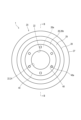
図3または図4に図示されるように、本体部20は、軸方向に貫通する穴部22を有する。軸方向から見た穴部22の形状は円形(正円形)である。図3に図示されるように、穴部22は、軸方向から見て本体部20(外周面部26)の略中央部に形成されている。好ましくは、軸方向に見て、穴部22の中心と本体部20(外周面部26)の中心とは一致する。
穴部22は、本体部20の内壁24によって画成される。内壁24は外周面部26の厚さと同じ寸法の幅を有する壁である。内壁24は軸方向およびボビン100の回転方向に延在している。
The details of the
The
The
The
As illustrated in FIG. 3 or 4, the
本実施形態における本体部20は、全体的に略均一な厚さを有する紙材が折曲げられて形成されている。
具体的には、本実施形態では、本体部20は、後述する外周面部26、側面部28、および鍔面部27を有する。外周面部26と側面部28との間の第一の折曲げ部(第一折曲げ部29)において、紙材は折曲げられている。また、鍔面部27と側面部28との間の第二折曲げ部23においても紙材は折曲げられている。
外周面部26とは、本体部20において穴部22が形成されている部分である。また、外周面部26は、当該穴部22を中心に軸方向と直交する径方向に延在している。径方向とは、より具体的には、軸方向から見て穴部22の中心から本体部20の周縁へ放射状に向かう方向である。
側面部28は、外周面部26の外周縁から軸方向の一方である第一方向(図5における左向き)に沿って延びる。ここで、外周面部26の外周縁部とは、径方向における外周面部26の外側の周縁である。なお、径方向における外周面部26の内側の周縁は、穴部22の内壁24である。側面部28が第一方向に沿って延びるとは、側面部28が径方向成分よりも大きな第一方向成分を有する方向に延在していることをいう。好ましくは、側面部28の延在方向は第一方向と略平行であるが、第一方向に対して若干斜めに傾いている。
鍔面部27は、側面部28の一端(軸方向における一端であって、外周面部26と反対側の一端)から径方向に沿って延びている。鍔面部27によって、ボビン本体110(図2参照)の内部(中空部113(図2参照))に留め具1が完全に入り込んでしまうことを抑制できる。
第一折曲げ部29は、側面部28と外周面部26との間に配置されている。また、第二折曲げ部23は、側面部28と鍔面部27との間に配置されている。第一折曲げ部29および第二折曲げ部23は、外周面部26、側面部28または鍔面部27よりも曲率半径が小さい部分である。
略均一な厚さの紙材が折曲げられて形成された本実施形態の本体部20に代えて、本体部20は、大きな厚さを有する紙材で形成されていてもよい。例えば、本実施形態の側面部28の軸方向における寸法と同等の厚さを有する紙材によって本体部20が形成されていてもよい。
The
Specifically, in this embodiment, the
The outer
The
The
The first
Instead of the
補強部40は本体部20に取付けられて、内壁24を覆う部材である。後述するように、爪部46が本体部20に係合し、かつ加締め部42が本体部20の一部を加締めることで補強部40が本体部20に取付けられていてもよいが、他の方法で補強部40が本体部20に取付けられてもよい。例えば、補強部40は本体部20に接着剤等の他の部材を用いて取付けられていてもよい。
補強部40は内壁24の少なくとも一部を覆い、好ましくは内壁24の全体を覆う。ここで補強部40が内壁24の全体を覆うとは、補強部40が軸方向における内壁24の全体を覆い、かつ、ボビン100の回転方向における内壁24の全体を覆っていることをいう。
補強部40を構成する金属は、例えばブリキ等が例示される。
The reinforcing
The reinforcing
Examples of the metal constituting the reinforcing
図5に図示されるように、加締め部42は、外周面部26における内端部26aを軸方向に挟むように配置されて当該内端部26aを加締めている。加締め部42は、補強部40の一部であって、内端部26aを軸方向の両側から挟んでいる一部である。また、加締め部42は内壁24も覆っている。
外周面部26における内端部26aとは、外周面部26における径方向の内側の端部である。内端部26aは内壁24を含む。このような加締め部42を設けることで、補強部40を本体部20に強固に取付けることができる。
ここで加締め部42が内端部26aを加締めるとは、加締め部42の一部と他の一部とで内端部26aが挟まれていることをいう。加締め部42の当該一部および当該他の一部は、内端部26aに接触していることが好ましいが、内端部26aと離間している箇所があってもよい。加締め部42の先端(後述する主面部44に続く一端と反対側の他端)側の一部は、本体部20(外周面部26)に圧接していても単に当接していてもよい。図6(a)に図示されるように、加締め部42の先端側の一部は、外周面部26の内部に嵌入していることが好ましい。すなわち、加締め部42の先端側の一部は、外周面部26の包絡体積内に配置されていることが好ましい。これに代えて、加締め部42の先端側の一部は外周面部26の内部に嵌入せずに、外周面部26の表面に沿って配置されていてもよい。より具体的には、外周面部26の内端部26aのうち加締め部42の先端側の一部に対応する箇所は窪み変形して凹部が形成されており、加締め部42の当該一部は、外周面部26の表面を突き破ることなくこの凹部に嵌合している。外周面部26の当該凹部の近傍は圧縮されて硬化している。このように、加締め部42の先端側の一部が外周面部26の内端部26aを突き破ることなく凹凸嵌合して圧接していることにより、シャフトからの外力が補強部40に負荷された際にも外周面部26の損耗が進展することを防止し、外力を補強部40の全体に分散させて本体部20に伝えることができる。
As illustrated in FIG. 5, the
The
Here, the crimping
図3に図示されるように、本実施形態において、補強部40は、加締め部42に隣接して径方向に延在する主面部44を有する。本実施形態において、主面部44は径方向に延在する円盤である。主面部44は、少なくとも外周面部26の主面26bにおける径方向の内側の一部を覆っている。本実施形態において、補強部40(主面部44)は、外周面部26の第二方向を向く主面26bを覆っている。これに代えて、補強部40(主面部44)は、外周面部26の第一方向を向く主面を覆っていてもよい。
図5に図示されるように、補強部40は、一または複数の爪部46を有する。爪部46は、主面部44から外周面部26に向けて突出している。爪部46は、外周面部26の内部に嵌入している。すなわち、爪部46は外周面部26の包絡体積内に配置されている。より具体的には、爪部46は外周面部26の表面(図6(a)における下側の表面)を突き破って外周面部26の内部に侵入することにより外周面部26の内部に嵌入している。
上述した構成により、補強部40は、加締め部42だけでなく、爪部46によっても本体部20に固定されている。特に、補強部40は爪部46によって本体部20における外周面部26に固定されている。これによって、シャフト200が回転したときの内壁24に加わる荷重が、本体部20における内壁24近傍だけでなく、本体部20における外周面部26の全体にもかかる。結果、本体部20の変形が好適に抑制される。
As illustrated in FIG. 3 , in this embodiment, the reinforcing
As illustrated in FIG. 5, the reinforcing
With the above-described configuration, the reinforcing
図6(a)に図示されるように、爪部46の先端部46aは外周面部26の内部に配置されて非露出であってもよい。この場合、爪部46の先端部46aは湾曲している。外周面部26の一部(主面部44に近接している一部)は、爪部46の先端部46aと主面部44の一部との間に挟まれて配置されている。以下において、爪部46が外周面部26の内部に配置されて非露出であって、湾曲した先端部と主面部とが外周面部26を挟んでいる上述の態様を、爪部46が外周面部26の内部で外周面部26と係合している、と呼ぶことがある。
このように爪部46が外周面部26の内部で外周面部26と係合していることによって、爪部46が本体部20から抜けることが好適に抑制される。
本実施形態において、爪部46は縦断面においてC字形状を有している。より具体的には、爪部46の基端部46cは主面部44よりもやや斜めに傾いて主面部44から立ち上がっている。換言すれば基端部46cは、軸方向(図6(a)における上下方向)成分よりも大きな径方向(穴部22の径方向であって、図6(a)における左右方向)成分を有する方向に延在している。また、爪部46の中間部46bは、基端部46cから反るように延びている。より具体的には、中間部46bは軸方向に対して傾いて延在しており、中間部46bは、基端部46cとの間に外周面部26の一部を挟むように配置されている。さらに具体的には、中間部46bは、後述する第二穴部48の径方向の外側に向けて延びている。
As illustrated in FIG. 6(a), the
By engaging the
In this embodiment, the
上述の態様に代えて、図6(b)に図示されるように、爪部46は外周面部26を貫通して、その先端は外周面部26の外部に露出していてもよい。この場合、図6(b)に図示されるように、外周面部26から露出した先端部46aは、爪部46の突出方向(軸方向に一致する)において外周面部26から真っ直ぐ突出していないことが好ましい。爪部46の鋭利な先端部46aが他の部材または作業者を傷つけることを抑制するためである。すなわち、好ましくは外周面部26の外部に露出する爪部46の先端部46aは、外周面部26の表面に沿って配置されている。ここで先端部46aが外周面部26の表面に沿って配置されているとは、先端部46aが屈曲または湾曲して外周面部26の表面の延在方向の成分を有する方向に延在していることである。
Instead of the above-mentioned embodiment, as shown in FIG. 6(b), the
本実施形態において、複数の爪部46のうち、一部の爪部46は、外周面部26の内部で外周面部26と係合している。また、複数の爪部のうち、他の爪部は、外周面部を貫通して、その先端は外周面部の外部に露出している。以下において、外周面部26の内部で外周面部26と係合している一部の爪部46を「非露出の爪部46」、外周面部26を貫通して先端が外周面部26の外部に露出している他の爪部を「露出の爪部46」とそれぞれ呼ぶことがある。すなわち、本実施形態において複数の爪部46のうち、一部は非露出の爪部46であり、他の一部は露出の爪部46である。
上述のような構成により、一部の爪部46が外周面部26の内部で外周面部26に係合することで当該爪部46は本体部20から抜けにくくなっている。一方で、他の一部の爪部は、外周面部26に軸方向に貫通することで補強部40(当該爪部46)にかかったシャフト200の荷重は、外周面部26の全厚さにかかることができ、外周面部26が十分にシャフト200の荷重を受けることができる。
本実施形態に代えて、複数の爪部46のすべてが露出の爪部46であってもよく、複数の爪部46のすべてが非露出の爪部46であってもよい。
In this embodiment, some of the
With the above configuration, some of the
Instead of this embodiment, all of the plurality of
図3に図示されるように、補強部40における主面部44には、第二穴部48が形成されている。第二穴部48は、軸方向に貫通している。また、第二穴部48は、軸方向から見て多角形の形状を有する。ここで第二穴部48の形状が多角形であるとは、当該多角形が認識できる形状であれば足る。すなわち、本実施形態のように、第二穴部48の形状が、隅部が曲線となっている略多角形(本実施形態では四辺形)である場合も、第二穴部48の形状が多角形であるという。本実施形態では、主面部44に複数(六つ)の第二穴部48が形成されており、当該複数の第二穴部48が回転方向に等間隔に配置されている。
図7(a)および図7(b)に図示されるように、複数の爪部46のそれぞれは、第二穴部48の多角形の各辺から突出した板形状を有する。本実施形態では後述するように、爪部46は三角形の板形状を有する。爪部46は、爪部46の突出方向に向けて幅寸法が小さくなるよう、第二穴部48の各辺から突出している。図3に図示されるように、軸方向から見て、内壁24と最も近接する一の辺(近接辺48a)は、内壁24と沿っている。
近接辺48aが内壁24に沿っていることにより、シャフト200の荷重が内壁24を覆う補強部40にかかったとき、当該荷重は近接辺48aから突出する爪部46に好適にかかるため、当該爪部によって補強部40が当該荷重を好適に受けることができる。
ここで、近接辺48aが内壁24と沿っているとは、内壁24のうちその近接辺48aに最も接近する位置における接線方向が当該近接辺48aの延在方向と概略平行であることをいう。言い換えると、近接辺48aの延在方向を穴部22の径方向の成分と穴部22の周方向(上記の近接する位置における内壁24の延在方向)の成分とに分解したときに、穴部22の径方向の成分よりも穴部22の周方向(回転方向)の成分の方が大きいことをいう。また、主面部44に複数の第二穴部48が形成されている場合は、複数の第二穴部48のうち少なくとも一部の一または複数の第二穴部48における近接辺48aが内壁24に沿っていればよい。
As illustrated in FIG. 3 , a
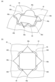
As illustrated in FIGS. 7A and 7B, each of the plurality of
Because the
Here, the
図7(a)および図7(b)に図示されるように、本実施形態において、爪部46は、板爪46eと、周回爪46dとを含む。板爪46eは、多角形の辺のそれぞれから突出する板形状の爪である。周回爪46dは、多角形の隅部のそれぞれから突出して板爪よりも突出寸法の小さい爪である。
図7(b)に図示されるように、板爪46eと周回爪46dとは一体的に形成されている。より具体的には、複数(四つ)の板爪46eおよび複数(四つ)の周回爪46dは第二穴部48の周方向に交互に配置されており、当該複数の板爪46eおよび複数の周回爪46dはすべて一体的に形成されている。また、爪部46は第二穴部の全周に渡って形成されている。
板爪46eは外周面部26(図6(a)または図6(b)を参照)の内部に嵌入している。一方、周回爪46dは外周面部26(図6(a)または図6(b)を参照)の主面に接触している。具体的には、周回爪46dに対応する位置において外周面部26の主面(表面)は凹状に窪んでおり、周回爪46dの先端または先端面は外周面部26の主面(表面)を突き破ることなくこの窪みに凹凸嵌合して接触し、これにより外周面部26の内部に嵌入している。周回爪46dの先端または先端面のすべてが外周面部26の主面に接触していても、していなくてもよい。周回爪46dの先端または先端面の一部は、外周面部26の主面に接触し、他の一部は外周面部26の内部に嵌入している、または外周面部26の主面と離間していてもよい。
上述のように、爪部46が第二穴部48を周回するように形成されており、板爪46eが外周面部26に嵌入している一方、周回爪46dが外周面部26の主面(表面)に接触していることで、爪部46と外周面部との係合だけでなく爪部46と外周面部26との摩擦によっても補強部40が外周面部26から外れること、または外周面部26に対してずれることが抑制される。
As illustrated in FIGS. 7(a) and 7(b), in this embodiment, the
As shown in FIG. 7(b), the
The
As described above, the
図6(a)または図6(b)に図示されるように、本実施形態の補強部40における主面部44の外周側の端部(外周端部44a)は、外周面部26の表面に配置されており、かつ、外周面部26に非固定である。これにより、外周端部44aと本体部20(外周面部26)との間に治具または手を差し込んで本体部20から補強部40を取外すことが容易となる。結果、本体部20から補強部40を容易に分離して廃棄できる。
外周端部44aが外周面部26の表面に配置されているとは、外周端部44aが外周面部26の外部に配置されており、また、外周面部26の表面に接触してまたは近接して配置されていることである。外周端部44aの全面が外周面部26と面接触していてもよく、外周端部44aの一部が外周面部26と接触していて、他の一部が外周面部26と離間していてもよい。
As illustrated in FIG. 6(a) or FIG. 6(b), the outer peripheral side end (outer
When the outer
図5に図示されるように、本実施形態において、第一折曲げ部29は、第一方向と反対向きの第二方向(図5における右向き)に向けて湾曲して膨らんでいる。
第一折曲げ部29が第二方向に向けて膨らんでいることにより、第一折曲げ部29は径方向にばね性を有する。これによって、シャフト200の荷重が内壁24に加わっても本体部20が第一折曲げ部29を起点に変形することが抑制される。例えば、外周面部26と側面部28とがなす角度が鋭角となるように第一折曲げ部29が変形することが抑制される。
第一折曲げ部29が第二方向に向けて湾曲して膨らんでいるとは、第一折曲げ部29を形成する紙材が第二方向に凸になるように湾曲しており、第一折曲げ部29の断面における外形が第二方向に向けて膨らんだ形状であることをいう。より具体的には、第一折曲げ部29の突出端は、外周面部26よりも第二方向において突出している。換言すれば、外周面部26は第一折曲げ部29よりも窪んでいる。
As illustrated in FIG. 5, in this embodiment, the first
Since the first
The fact that the first
(ボビン)
図2に図示されるように、上記で説明した留め具1は、当該留め具1を含むボビン100として提供されてもよい。
上述したように、ボビン100は、長尺の被巻取物が巻き取られる部品である。ボビン100は、ボビン本体110と、留め具1と、を有する。ボビン本体110は、被巻取物が巻き付けられて軸方向に延在する。上述したように留め具1は、ボビン本体110の端部に取付けられ、ボビン本体110を回転させるためのシャフト200が挿入される穴部22が形成されている。
(bobbin)
As illustrated in FIG. 2, the
As described above, the
上述したように、ボビン本体110は、巻回部111および一対の鍔部112,112を有する。本実施形態において、巻回部111および一対の鍔部112は互いに分離した部材である。巻回部111および鍔部112は別の材料で形成されていてもよく、異なる部材で形成されていてもよい。上述したように、巻回部111は被巻取物を巻回する中空の部材であり、鍔部112は軸方向における巻回部111の両端に配置された部材である。
図2に図示されるように、本実施形態では、側面部28が巻回部111の内壁24に沿うように、本体部20は巻回部111の中空(中空部113)に挿入されている。これによって、留め具1はボビン本体110に取付けられている。
本実施形態において、鍔部112の内径は、巻回部111の内径よりも大きい。そのため、径方向において、鍔部112の内壁(径方向内側を向く面)は巻回部111の内壁(中空部113を画成する面)よりも外側に配置されている。巻回部111の内壁は、側面部28に接触しており、鍔部112の内壁は、側面部28と離間している。
このように、鍔部112の内壁が巻回部111の内壁よりも径方向外側に配置されていることで、側面部28が良好に巻回部111の内壁に面接触できる。具体的には、側面部28と鍔面部27との間の第二折曲げ部23が曲面で構成されている場合でも、側面部28が良好に巻回部111の内壁に面接触できる。鍔部112の内壁が径方向のより外側に配置されていることで、鍔部112と第二折曲げ部23とが干渉することが抑制されるからである。
本実施形態において、鍔部112の主面(特に、軸方向の内側を向く面。他の鍔部112の方を向く面。)と巻回部111の端面(軸方向を向く面)とが接触している。より具体的には、巻回部111の端面における径方向外側の一部が鍔部112の主面と接触しており、巻回部111の端面における径方向内側の一部は鍔部112の主面と非接触であって離間している。
本実施形態に代えて、巻回部111および鍔部112は一体的に形成されていてもよい。
As described above, the bobbin
As illustrated in FIG. 2, in this embodiment, the
In this embodiment, the inner diameter of the
In this manner, the inner wall of the
In this embodiment, the main surface of the flange 112 (particularly the surface facing inward in the axial direction; the surface facing the other flange 112) and the end surface (the surface facing the axial direction) of the winding
Instead of this embodiment, the winding
なお、本考案は上述の実施形態に限定されるものではなく、本考案の目的が達成される限りにおける種々の変形、改良等の態様も含む。 Note that the present invention is not limited to the above-described embodiments, and includes various modifications and improvements as long as the object of the present invention is achieved.
上記実施形態は、以下の技術思想を包含するものである。
(1)長尺の被巻取物が巻き取られるボビンにおいて当該ボビンの軸方向の端部に取付けられ、前記ボビンを回転させるためのシャフトが挿入される穴部が形成された留め具であって、
前記軸方向における前記ボビンの端部に固定され、前記軸方向に貫通する前記穴部を有する紙製の本体部と、
前記本体部に固定され、前記穴部を画成する内壁を覆う金属製の補強部と、を有する、留め具。
(2)前記補強部は、前記内壁の全体を覆っている、(1)に記載の留め具。
(3)前記本体部は、
前記穴部が形成されて当該穴部を中心に前記軸方向と直交する径方向に延在する外周面部を有し、
前記外周面部の前記径方向の内側の端部である内端部は前記内壁を含み、
前記補強部の一部である加締め部は、前記内端部を前記軸方向に挟むように配置されて当該内端部を加締めている、(1)に記載の留め具。
(4)前記補強部は、前記加締め部に隣接して前記径方向に延在する主面部を有し、
前記主面部は、少なくとも前記外周面部の主面における前記径方向の内側の一部を覆っており、
前記補強部は、前記主面部から前記外周面部に向けて突出して前記外周面部の内部に嵌入する一または複数の爪部を有する、(3)に記載の留め具。
(5)前記爪部の先端部は前記外周面部の内部に配置されて非露出であり、
前記先端部は湾曲しており、
前記外周面部の一部は、前記爪部の先端と前記主面部の一部との間に挟まれて配置されている、(4)に記載の留め具。
(6)前記複数の前記爪部のうち、
一部の前記爪部の先端部は前記外周面部の内部に配置されて非露出であり、
当該先端部は湾曲しており、
前記外周面部の一部は、当該一部の前記爪部の先端と前記主面部の一部との間に挟まれて配置されており、
前記複数の前記爪部のうち、
他の前記爪部は前記外周面部を貫通して、その先端は前記外周面部の外部に露出している、(4)に記載の留め具。
(7)前記主面部には前記軸方向に貫通して前記軸方向から見て多角形の形状を有する第二穴部が形成されており、
前記複数の前記爪部のそれぞれは、前記多角形の各辺から突出した板形状を有し、
前記軸方向から見て、前記内壁と最も近接する一の前記辺は、前記内壁と沿っている、(5)または(6)に記載の留め具。
(8)前記爪部は、前記多角形の辺のそれぞれから突出する前記板形状の板爪と、前記多角形の隅部のそれぞれから突出して前記板爪よりも突出寸法の小さい周回爪と、を含み、
前記板爪と前記周回爪とは一体的に形成され、前記爪部は前記第二穴部の全周に渡って形成されており、
前記板爪は前記外周面部の内部に嵌入し、
前記周回爪は前記外周面部の主面に接触している、(7)に記載の留め具。
(9)前記主面部の外周側の端部は、
前記外周面部の表面に配置されており、
前記外周面部に非固定である、(8)に記載の留め具。
(10)前記本体部は、
前記外周面部の外周縁から前記軸方向の一方である第一方向に沿って延びる側面部と、
前記側面部と前記外周面部との間に配置された折曲げ部と、を有し、
前記折曲げ部は、前記第一方向と反対向きの第二方向に向けて湾曲して膨らんでいる、(9)に記載の留め具。
(11)長尺の被巻取物が巻き取られるボビンであって、
前記被巻取物が巻き付けられて軸方向に延在するボビン本体と、
前記ボビン本体の端部に取付けられ、前記ボビン本体を回転させるためのシャフトが挿入される穴部が形成された留め具と、を有し、
前記留め具は、
前記軸方向における前記ボビン本体の端部に固定され、前記軸方向に貫通する前記穴部を有する紙製の本体部と、
前記本体部に固定され、前記穴部を画成する内壁を覆う金属製の補強部と、を備える、ボビン。
(12)前記本体部は、
前記穴部が形成されて当該穴部を中心に前記軸方向と直交する径方向に延在する外周面部を有し、
前記外周面部の前記径方向の内側の端部である内端部は前記内壁を含み、
前記補強部の一部である加締め部は、前記内端部を前記軸方向に挟むように配置されて当該内端部を加締めている、(11)に記載のボビン。
(13)前記補強部は、前記加締め部に隣接して前記径方向に延在する主面部を有し、
前記主面部は、少なくとも前記外周面部の主面における前記径方向の内側の一部を覆っており、
前記補強部は、前記主面部から前記外周面部に向けて突出して前記外周面部の内部に嵌入する一または複数の爪部を有する、(12)に記載のボビン。
(14)前記爪部の先端部は前記外周面部の内部に配置されて非露出であり、
前記先端部は湾曲しており、
前記外周面部の一部は、前記爪部の先端と前記主面部の一部との間に挟まれて配置されている、(13)に記載のボビン。
(15)前記複数の前記爪部のうち、
一部の前記爪部の先端部は前記外周面部の内部に配置されて非露出であり、
当該先端部は湾曲しており、
前記外周面部の一部は、当該一部の前記爪部の先端と前記主面部の一部との間に挟まれて配置されており、
前記複数の前記爪部のうち、
他の前記爪部は前記外周面部を貫通して、その先端は前記外周面部の外部に露出している、(13)に記載のボビン。
(16)前記主面部には前記軸方向に貫通して前記軸方向から見て多角形の形状を有する第二穴部が形成されており、
前記複数の前記爪部のそれぞれは、前記多角形の各辺から突出した板形状を有し、
前記軸方向から見て、前記内壁と最も近接する一の前記辺は、前記内壁と沿っている、(14)または(15)に記載のボビン。
(17)ボビン本体は、
前記被巻取物を巻回する中空の巻回部と、前記軸方向における前記巻回部の両端に配置された一対の鍔部と、を備え、
前記留め具における前記本体部は、
前記外周面部の外周縁から前記軸方向の一方である第一方向に沿って延びる側面部と、
前記側面部と前記外周面部との間に配置された折曲げ部と、を有し、
前記側面部が前記巻回部の内壁に沿うように前記本体部は前記巻回部の中空に挿入されることで前記留め具は前記ボビン本体に取付けられており、
前記鍔部の内径は、前記巻回部の内径よりも大きく、
前記軸方向に直交する径方向において、前記鍔部の内壁は前記巻回部の内壁よりも外側に配置されており、
前記巻回部の前記内壁は、前記側面部に接触しており、
前記鍔部の前記内壁は、前記側面部と離間している、(16)に記載のボビン。
The above embodiment includes the following technical ideas.
(1) A fastener that is attached to the axial end of a bobbin on which a long object is wound, and has a hole into which a shaft for rotating the bobbin is inserted. hand,
a paper main body portion fixed to an end of the bobbin in the axial direction and having the hole portion penetrating in the axial direction;
A fastener comprising: a metal reinforcing portion fixed to the main body portion and covering an inner wall defining the hole portion.
(2) The fastener according to (1), wherein the reinforcing portion covers the entire inner wall.
(3) The main body portion is
having an outer circumferential surface portion in which the hole portion is formed and extends in a radial direction perpendicular to the axial direction around the hole portion;
An inner end portion that is an inner end portion in the radial direction of the outer circumferential surface portion includes the inner wall,
The fastener according to (1), wherein the caulking portion, which is a part of the reinforcing portion, is arranged to sandwich the inner end portion in the axial direction and caulks the inner end portion.
(4) the reinforcing portion has a main surface portion adjacent to the caulking portion and extending in the radial direction;
The main surface portion covers at least a part of the inner side in the radial direction of the main surface of the outer circumferential surface portion,
The fastener according to (3), wherein the reinforcing portion has one or more claw portions that protrude from the main surface toward the outer circumferential surface and fit into the outer circumferential surface.
(5) The tip of the claw portion is disposed inside the outer circumferential surface portion and is not exposed;
The tip is curved,
The fastener according to (4), wherein a portion of the outer circumferential surface portion is sandwiched between a tip of the claw portion and a portion of the main surface portion.
(6) Among the plurality of claw parts,
The tip portions of some of the claw portions are disposed inside the outer circumferential surface portion and are not exposed;
The tip is curved,
A portion of the outer peripheral surface portion is disposed between a tip of the claw portion of the portion and a portion of the main surface portion,
Among the plurality of claw parts,
The fastener according to (4), wherein the other claw portion passes through the outer circumferential surface portion, and a tip thereof is exposed to the outside of the outer circumferential surface portion.
(7) A second hole is formed in the main surface portion, penetrating in the axial direction and having a polygonal shape when viewed from the axial direction;
Each of the plurality of claw portions has a plate shape protruding from each side of the polygon,
The fastener according to (5) or (6), wherein one of the sides closest to the inner wall when viewed from the axial direction is along the inner wall.
(8) The claw portion includes the plate-shaped plate claw protruding from each side of the polygon, and a circular claw protruding from each corner of the polygon and having a smaller protruding dimension than the plate claw, including;
The plate claw and the circumferential claw are integrally formed, and the claw portion is formed over the entire circumference of the second hole,
The plate claw fits inside the outer peripheral surface portion,
The fastener according to (7), wherein the circumferential claw is in contact with the main surface of the outer circumferential surface portion.
(9) The outer peripheral side end of the main surface portion is
disposed on the surface of the outer peripheral surface portion,
The fastener according to (8), which is not fixed to the outer peripheral surface portion.
(10) The main body portion is
a side surface portion extending from an outer peripheral edge of the outer peripheral surface portion along a first direction that is one of the axial directions;
a bent portion disposed between the side surface portion and the outer circumferential surface portion;
The fastener according to (9), wherein the bent portion is curved and bulged in a second direction opposite to the first direction.
(11) A bobbin on which a long object is wound,
a bobbin body around which the material to be wound is wound and extends in the axial direction;
a fastener that is attached to an end of the bobbin body and has a hole formed therein into which a shaft for rotating the bobbin body is inserted;
The fastener is
a paper main body portion fixed to an end of the bobbin main body in the axial direction and having the hole portion penetrating in the axial direction;
A bobbin, comprising: a metal reinforcement part fixed to the main body part and covering an inner wall defining the hole part.
(12) The main body portion is
having an outer circumferential surface portion in which the hole portion is formed and extends in a radial direction perpendicular to the axial direction around the hole portion;
An inner end portion that is an inner end portion in the radial direction of the outer circumferential surface portion includes the inner wall,
The bobbin according to (11), wherein the caulking portion, which is a part of the reinforcing portion, is arranged to sandwich the inner end portion in the axial direction and caulks the inner end portion.
(13) The reinforcing portion has a main surface portion adjacent to the caulking portion and extending in the radial direction,
The main surface portion covers at least a part of the inner side in the radial direction of the main surface of the outer circumferential surface portion,
The bobbin according to (12), wherein the reinforcing portion has one or more claw portions that protrude from the main surface toward the outer circumferential surface and fit into the outer circumferential surface.
(14) The tip of the claw portion is disposed inside the outer circumferential surface portion and is not exposed;
The tip is curved,
The bobbin according to (13), wherein a portion of the outer circumferential surface portion is sandwiched between a tip of the claw portion and a portion of the main surface portion.
(15) Among the plurality of claw parts,
The tip portions of some of the claw portions are disposed inside the outer circumferential surface portion and are not exposed;
The tip is curved,
A portion of the outer peripheral surface portion is disposed between a tip of the claw portion of the portion and a portion of the main surface portion,
Among the plurality of claw portions,
The bobbin according to (13), wherein the other claw portion passes through the outer circumferential surface portion, and a tip thereof is exposed to the outside of the outer circumferential surface portion.
(16) A second hole is formed in the main surface portion, penetrating in the axial direction and having a polygonal shape when viewed from the axial direction;
Each of the plurality of claw portions has a plate shape protruding from each side of the polygon,
The bobbin according to (14) or (15), wherein one of the sides closest to the inner wall when viewed from the axial direction is along the inner wall.
(17) The bobbin body is
comprising a hollow winding part for winding the object to be wound, and a pair of collar parts disposed at both ends of the winding part in the axial direction,
The main body portion of the fastener includes:
a side surface portion extending from an outer peripheral edge of the outer peripheral surface portion along a first direction that is one of the axial directions;
a bent portion disposed between the side surface portion and the outer circumferential surface portion;
The fastener is attached to the bobbin main body by inserting the main body into the hollow of the winding part so that the side surface portion runs along the inner wall of the winding part,
The inner diameter of the collar portion is larger than the inner diameter of the winding portion,
In a radial direction perpendicular to the axial direction, an inner wall of the collar portion is arranged outside an inner wall of the winding portion,
The inner wall of the winding portion is in contact with the side surface portion,
The bobbin according to (16), wherein the inner wall of the collar portion is spaced apart from the side surface portion.
1 留め具
20 本体部
22 穴部
23 第二折曲げ部
24 内壁
26 外周面部
26a 内端部
26b 主面
27 鍔面部
28 側面部
29 第一折曲げ部
40 補強部
42 加締め部
44 主面部
44a 外周端部
46 爪部
46a 先端部
46b 中間部
46c 基端部
46d 周回爪
46e 板爪
48 第二穴部
48a 近接辺
100 ボビン
110 ボビン本体
111 巻回部
112 鍔部
113 中空部
200 シャフト
1
Claims (17)
前記軸方向における前記ボビンの端部に固定され、前記軸方向に貫通する前記穴部を有する紙製の本体部と、
前記本体部に固定され、前記穴部を画成する内壁を覆う金属製の補強部と、を有する、留め具。 A fastener that is attached to an axial end of a bobbin on which a long object is wound, and has a hole into which a shaft for rotating the bobbin is inserted,
a paper main body portion fixed to an end of the bobbin in the axial direction and having the hole portion penetrating in the axial direction;
A fastener comprising: a metal reinforcing portion fixed to the main body portion and covering an inner wall defining the hole portion.
前記穴部が形成されて当該穴部を中心に前記軸方向と直交する径方向に延在する外周面部を有し、
前記外周面部の前記径方向の内側の端部である内端部は前記内壁を含み、
前記補強部の一部である加締め部は、前記内端部を前記軸方向に挟むように配置されて当該内端部を加締めている、請求項1に記載の留め具。 The main body portion is
having an outer circumferential surface portion in which the hole portion is formed and extends in a radial direction perpendicular to the axial direction around the hole portion;
An inner end portion that is an inner end portion in the radial direction of the outer circumferential surface portion includes the inner wall,
The fastener according to claim 1, wherein the caulking portion that is a part of the reinforcing portion is arranged to sandwich the inner end portion in the axial direction and caulks the inner end portion.
前記主面部は、少なくとも前記外周面部の主面における前記径方向の内側の一部を覆っており、
前記補強部は、前記主面部から前記外周面部に向けて突出して前記外周面部の内部に嵌入する一または複数の爪部を有する、請求項3に記載の留め具。 The reinforcing portion has a main surface portion adjacent to the caulking portion and extending in the radial direction,
The main surface portion covers at least a part of the inner side in the radial direction of the main surface of the outer circumferential surface portion,
The fastener according to claim 3, wherein the reinforcing portion has one or more claw portions that protrude from the main surface toward the outer circumferential surface and fit into the outer circumferential surface.
前記先端部は湾曲しており、
前記外周面部の一部は、前記爪部の先端と前記主面部の一部との間に挟まれて配置されている、請求項4に記載の留め具。 The tip of the claw portion is disposed inside the outer circumferential surface portion and is not exposed;
The tip is curved,
The fastener according to claim 4, wherein a portion of the outer circumferential surface portion is sandwiched between a tip of the claw portion and a portion of the main surface portion.
一部の前記爪部の先端部は前記外周面部の内部に配置されて非露出であり、
当該先端部は湾曲しており、
前記外周面部の一部は、当該一部の前記爪部の先端と前記主面部の一部との間に挟まれて配置されており、
前記複数の前記爪部のうち、
他の前記爪部は前記外周面部を貫通して、その先端は前記外周面部の外部に露出している、請求項4に記載の留め具。 Among the plurality of claw parts,
The tip portions of some of the claw portions are disposed inside the outer circumferential surface portion and are not exposed;
The tip is curved,
A portion of the outer peripheral surface portion is disposed between a tip of the claw portion of the portion and a portion of the main surface portion,
Among the plurality of claw parts,
5. The fastener according to claim 4, wherein the other claw portion passes through the outer circumferential surface portion, and a tip thereof is exposed to the outside of the outer circumferential surface portion.
前記複数の前記爪部のそれぞれは、前記多角形の各辺から突出した板形状を有し、
前記軸方向から見て、前記内壁と最も近接する一の前記辺は、前記内壁と沿っている、請求項5または6に記載の留め具。 A second hole is formed in the main surface portion and penetrates in the axial direction and has a polygonal shape when viewed from the axial direction,
Each of the plurality of claw portions has a plate shape protruding from each side of the polygon,
The fastener according to claim 5 or 6, wherein one of the sides closest to the inner wall when viewed from the axial direction is along the inner wall.
前記板爪と前記周回爪とは一体的に形成され、前記爪部は前記第二穴部の全周に渡って形成されており、
前記板爪は前記外周面部の内部に嵌入し、
前記周回爪は前記外周面部の主面に接触している、請求項7に記載の留め具。 The claw portion includes the plate-shaped plate claw protruding from each side of the polygon, and a circular claw protruding from each corner of the polygon and having a smaller protrusion dimension than the plate claw,
The plate claw and the circumferential claw are integrally formed, and the claw portion is formed over the entire circumference of the second hole,
The plate claw fits inside the outer peripheral surface portion,
The fastener according to claim 7, wherein the circumferential claw is in contact with a main surface of the outer circumferential surface portion.
前記外周面部の表面に配置されており、
前記外周面部に非固定である、請求項8に記載の留め具。 The outer peripheral side end of the main surface portion is
disposed on the surface of the outer peripheral surface portion,
The fastener according to claim 8, wherein the fastener is not fixed to the outer peripheral surface portion.
前記外周面部の外周縁から前記軸方向の一方である第一方向に沿って延びる側面部と、
前記側面部と前記外周面部との間に配置された折曲げ部と、を有し、
前記折曲げ部は、前記第一方向と反対向きの第二方向に向けて湾曲して膨らんでいる、請求項9に記載の留め具。 The main body portion is
a side surface portion extending from an outer peripheral edge of the outer peripheral surface portion along a first direction that is one of the axial directions;
a bent portion disposed between the side surface portion and the outer circumferential surface portion;
The fastener according to claim 9, wherein the bent portion is curved and bulged in a second direction opposite to the first direction.
前記被巻取物が巻き付けられて軸方向に延在するボビン本体と、
前記ボビン本体の端部に取付けられ、前記ボビン本体を回転させるためのシャフトが挿入される穴部が形成された留め具と、を有し、
前記留め具は、
前記軸方向における前記ボビン本体の端部に固定され、前記軸方向に貫通する前記穴部を有する紙製の本体部と、
前記本体部に固定され、前記穴部を画成する内壁を覆う金属製の補強部と、を備える、ボビン。 A bobbin on which a long material to be wound is wound,
a bobbin body around which the material to be wound is wound and extends in the axial direction;
a fastener that is attached to an end of the bobbin body and has a hole formed therein into which a shaft for rotating the bobbin body is inserted;
The fastener is
a paper main body portion fixed to an end of the bobbin main body in the axial direction and having the hole portion penetrating in the axial direction;
A bobbin, comprising: a metal reinforcement part fixed to the main body part and covering an inner wall defining the hole part.
前記穴部が形成されて当該穴部を中心に前記軸方向と直交する径方向に延在する外周面部を有し、
前記外周面部の前記径方向の内側の端部である内端部は前記内壁を含み、
前記補強部の一部である加締め部は、前記内端部を前記軸方向に挟むように配置されて当該内端部を加締めている、請求項11に記載のボビン。 The main body portion is
having an outer circumferential surface portion in which the hole portion is formed and extends in a radial direction perpendicular to the axial direction around the hole portion;
An inner end portion that is an inner end portion in the radial direction of the outer circumferential surface portion includes the inner wall,
The bobbin according to claim 11, wherein the caulking portion, which is a part of the reinforcing portion, is arranged to sandwich the inner end portion in the axial direction and caulks the inner end portion.
前記主面部は、少なくとも前記外周面部の主面における前記径方向の内側の一部を覆っており、
前記補強部は、前記主面部から前記外周面部に向けて突出して前記外周面部の内部に嵌入する一または複数の爪部を有する、請求項12に記載のボビン。 The reinforcing portion has a main surface portion adjacent to the caulking portion and extending in the radial direction,
The main surface portion covers at least a part of the inner side in the radial direction of the main surface of the outer circumferential surface portion,
The bobbin according to claim 12, wherein the reinforcing portion has one or more claw portions that protrude from the main surface toward the outer circumferential surface and fit into the outer circumferential surface.
前記先端部は湾曲しており、
前記外周面部の一部は、前記爪部の先端と前記主面部の一部との間に挟まれて配置されている、請求項13に記載のボビン。 The tip of the claw portion is disposed inside the outer circumferential surface portion and is not exposed;
The tip is curved,
14. The bobbin according to claim 13, wherein a part of the outer circumferential surface part is sandwiched between a tip of the claw part and a part of the main surface part.
一部の前記爪部の先端部は前記外周面部の内部に配置されて非露出であり、
当該先端部は湾曲しており、
前記外周面部の一部は、当該一部の前記爪部の先端と前記主面部の一部との間に挟まれて配置されており、
前記複数の前記爪部のうち、
他の前記爪部は前記外周面部を貫通して、その先端は前記外周面部の外部に露出している、請求項13に記載のボビン。 Among the plurality of claw parts,
The tip portions of some of the claw portions are disposed inside the outer circumferential surface portion and are not exposed;
The tip is curved,
A portion of the outer peripheral surface portion is disposed between a tip of the claw portion of the portion and a portion of the main surface portion,
Among the plurality of claw parts,
The bobbin according to claim 13, wherein the other claw portion passes through the outer circumferential surface portion, and a tip thereof is exposed to the outside of the outer circumferential surface portion.
前記複数の前記爪部のそれぞれは、前記多角形の各辺から突出した板形状を有し、
前記軸方向から見て、前記内壁と最も近接する一の前記辺は、前記内壁と沿っている、請求項14または15に記載のボビン。 A second hole is formed in the main surface portion, penetrating in the axial direction and having a polygonal shape when viewed from the axial direction,
Each of the plurality of claw portions has a plate shape protruding from each side of the polygon,
The bobbin according to claim 14 or 15, wherein one of the sides closest to the inner wall when viewed from the axial direction is along the inner wall.
前記被巻取物を巻回する中空の巻回部と、前記軸方向における前記巻回部の両端に配置された一対の鍔部と、を備え、
前記留め具における前記本体部は、
前記外周面部の外周縁から前記軸方向の一方である第一方向に沿って延びる側面部と、
前記側面部と前記外周面部との間に配置された折曲げ部と、を有し、
前記側面部が前記巻回部の内壁に沿うように前記本体部は前記巻回部の中空に挿入されることで前記留め具は前記ボビン本体に取付けられており、
前記鍔部の内径は、前記巻回部の内径よりも大きく、
前記軸方向に直交する径方向において、前記鍔部の内壁は前記巻回部の内壁よりも外側に配置されており、
前記巻回部の前記内壁は、前記側面部に接触しており、
前記鍔部の前記内壁は、前記側面部と離間している、請求項16に記載のボビン。 The bobbin body is
comprising a hollow winding part for winding the object to be wound, and a pair of collar parts disposed at both ends of the winding part in the axial direction,
The main body portion of the fastener includes:
a side surface portion extending from an outer peripheral edge of the outer peripheral surface portion along a first direction that is one of the axial directions;
a bent portion disposed between the side surface portion and the outer circumferential surface portion;
The fastener is attached to the bobbin main body by inserting the main body into the hollow of the winding part such that the side surface portion runs along the inner wall of the winding part,
The inner diameter of the collar portion is larger than the inner diameter of the winding portion,
In a radial direction perpendicular to the axial direction, an inner wall of the collar portion is arranged outside an inner wall of the winding portion,
The inner wall of the winding portion is in contact with the side surface portion,
The bobbin according to claim 16, wherein the inner wall of the collar is spaced apart from the side surface.
Priority Applications (1)
| Application Number | Priority Date | Filing Date | Title |
|---|---|---|---|
| JP2024000186U JP3246110U (en) | 2024-01-24 | 2024-01-24 | Fasteners and bobbins |
Applications Claiming Priority (1)
| Application Number | Priority Date | Filing Date | Title |
|---|---|---|---|
| JP2024000186U JP3246110U (en) | 2024-01-24 | 2024-01-24 | Fasteners and bobbins |
Publications (1)
| Publication Number | Publication Date |
|---|---|
| JP3246110U true JP3246110U (en) | 2024-03-22 |
Family
ID=90272564
Family Applications (1)
| Application Number | Title | Priority Date | Filing Date |
|---|---|---|---|
| JP2024000186U Active JP3246110U (en) | 2024-01-24 | 2024-01-24 | Fasteners and bobbins |
Country Status (1)
| Country | Link |
|---|---|
| JP (1) | JP3246110U (en) |
-
2024
- 2024-01-24 JP JP2024000186U patent/JP3246110U/en active Active
Similar Documents
| Publication | Publication Date | Title |
|---|---|---|
| JP6610922B2 (en) | Motor built-in roller and power transmission member | |
| JP4634299B2 (en) | Lip type seal | |
| US10549944B2 (en) | Paper-made reel | |
| KR20200121882A (en) | Radial foil bearing | |
| JP2011094797A (en) | Hose clamp | |
| CN110799765A (en) | Radial foil bearings | |
| KR20040012557A (en) | One-way clutch | |
| JP6744194B2 (en) | Bearing holding structure and motor | |
| EP0200815A1 (en) | Mounting shaft to pulley formed of sheet metal | |
| JP2009138934A (en) | Worm thread clamp | |
| JP4865153B2 (en) | Fixed element magazine | |
| US20060076199A1 (en) | Brake band | |
| JPS5836213Y2 (en) | small motor | |
| WO2019172301A1 (en) | Radial foil bearing | |
| JP2024077751A (en) | Cable drum | |
| CN204852069U (en) | Clutch housing assembly | |
| JPS6177179A (en) | Hub for tape reel | |
| JPH08262926A (en) | Ground plate structure of photoconductor drum | |
| JP2767525B2 (en) | Packaging material for holding fans | |
| JP4648222B2 (en) | Paper drum | |
| JP3148447U (en) | Electric drum | |
| JP2019023490A (en) | Band fastener | |
| JPH0743816Y2 (en) | Tape reel | |
| JP2024175694A (en) | Paper Reel | |
| JP4234526B2 (en) | End plate fixing structure of rotating electric machine and rotating electric machine |
Legal Events
| Date | Code | Title | Description |
|---|---|---|---|
| R150 | Certificate of patent or registration of utility model |
Ref document number: 3246110 Country of ref document: JP Free format text: JAPANESE INTERMEDIATE CODE: R150 |