JP3542246B2 - Cleaning device for transfer conveyor belt - Google Patents
Cleaning device for transfer conveyor belt Download PDFInfo
- Publication number
- JP3542246B2 JP3542246B2 JP34679396A JP34679396A JP3542246B2 JP 3542246 B2 JP3542246 B2 JP 3542246B2 JP 34679396 A JP34679396 A JP 34679396A JP 34679396 A JP34679396 A JP 34679396A JP 3542246 B2 JP3542246 B2 JP 3542246B2
- Authority
- JP
- Japan
- Prior art keywords
- transfer
- belt
- sponge roller
- cleaning device
- conveyance belt
- Prior art date
- Legal status (The legal status is an assumption and is not a legal conclusion. Google has not performed a legal analysis and makes no representation as to the accuracy of the status listed.)
- Expired - Fee Related
Links
Images



Landscapes
- Paper Feeding For Electrophotography (AREA)
- Electrostatic Charge, Transfer And Separation In Electrography (AREA)
Description
【0001】
【発明の属する技術分野】
本発明は、複写機、ファックス等の画像形成装置において用いられる転写搬送ベルトのクリーニング装置に関する。
【0002】
【従来の技術】
画像形成装置における転写搬送ベルトは、転写部で転写した後、静電吸着した転写紙を排紙部へ搬送するものであり、転写搬送ベルトの汚れは画像形成装置の画像品質に大きな影響を与え、これを除去することが重要である。そして、転写搬送ベルト成形時に問題となるのが、伸びのある弾性体ベルトにどのようにして低摩擦係数の材料、即ち、硬い材料をコーティングするかである。低摩擦係数の材料は、硬いほど摩擦係数が低くなって本来の性質を発揮するのであるが、これを弾性体ベルトにコーティングすると、ベルトの張力が高くなって伸びなくなる。この状態のベルトを無理に伸ばそうとすると、ベルト表面の被膜層に亀裂が入り、同亀裂部にトナーが入り込んでしまい、クリーニングブレードやブラシなどで掻き取れなくなり、転写搬送ベルト表面のクリーニング不良が発生するという問題がある。
【0003】
反対に、低摩擦係数の材料に比較的柔らかい材料を用いて弾性体ベルトに追従できるようにすると、ベルトの張力がそれ程高くならず、亀裂の発生は抑えられるものの、ベルト表面の摩擦係数が高くなってトナーの離形性が良くなくなり、やはり、転写搬送ベルトのクリーニング不良を招いてしまうという問題がある。このように転写搬送ベルトのクリーニングには課題が多く、経時にわたって完全にクリーニング性を維持することは難しい。
【0004】
また別の課題として紙粉によるクリーニング不良の問題がある。転写搬送ベルトは紙と接触する為、ベルトに付着した紙粉がクリーニングブレードエッジに食い込むと、ブレードエッジのトナーかき落とし能力が低下して、クリーニング不良となり易い。特に紙が給紙コロに摺擦される部分(一般に紙中央部が多い)の紙粉発生が多く、特に紙のその部分に対応するベルト領域(一般にベルト中央部)でのクリーニング不良が多くなる。
【0005】
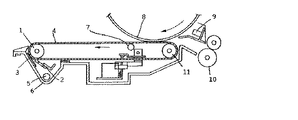
ここで紙粉クリーニング不良の対策として従来以下のようなことを実施してきている。即ち、図1に示したように転写ユニットの駆動ローラ1に対向してクリーニングブレード2の上流側、具体的には転写部から図示せぬ定着、排紙部(図1の左側に位置する。)への搬送方向(図1中に矢印で示す。)に沿って転写部の下流側でかつクリーニングブレード2の上流側に、シール部材3を設けてある。シール部材3は植毛されたブラシ形状のもので、一般的に導電性アクリル繊維や絶縁性のポリエステル繊維の材質のものが用いられ、転写搬送ベルト4に接触する状態で設けられている。これにより転写搬送ベルト4上の紙粉はある程度除去され、またシール部材3はクリーニングブレード2でかき落とされたトナーが飛散してユニット周辺を汚すことを防止するためのシールの機能も発揮する。但し、紙粉は100%シール部材3では除去できないため、シール部材3を通過した紙粉はクリーニングブレード2のエッジに滞留する。その紙粉除去として、コピー機の1ジョブ終了の際の転写搬送ベルトユニットの停止時に、駆動モータを逆転させて転写搬送ベルト4を逆転し、クリーニングブレード2のエッジに食い込んだ紙粉を除去することを行っている。なお、図中5はトナー回収コイル、6は下ケース、7はバイアスローラ、8は感光体ドラム、9は転写前除電ランプ、10はレジストローラ、11は従動ローラである。
【0006】
【発明が解決しようとする課題】
前述した従来の装置は、図1に示すように駆動ローラ1に対向してクリーニングブレード2の上流側にシール部材3が設けてあるが、このシール部材3は下ケース6に固定式のため、装置稼働の初期においては紙粉除去効果は高いが、徐々にシール部材3に紙粉が溜まり、経時的に除去効果が低下してしまうという問題がある。
【0007】
さらに近年は、リサイクルペーパーと呼ばれている再生紙の使用増加による問題がある。即ち、リサイクルペーパーは純正パルプ紙に比べて繊維が繁雑で裁断面から非常に多くの紙粉を発生させやすく、その結果、このようなリサイクルペーパーを多く使用する場合、固定式のシール部材3ではますます紙粉除去に関する耐久性が低下してしまうというものである。
【0008】
そこで本発明は、転写搬送ベルトと接触する部分を常にリフレッシュさせることができ、経時的に安定した紙粉除去を行え、従って近年のリサイクルペーパーの使用にも対応できる転写搬送ベルトのクリーニング装置を提供することを目的とする。
【0009】
【課題を解決するための手段】
本発明の転写搬送ベルトのクリーニング装置のうち請求項1に係るものは、上記目的を達成するために、転写紙を転写部で転写した後、そのまま静電吸着させて定着、排紙部へ搬送する転写搬送ベルトのクリーニング装置において、上記転写搬送ベルトの上記転写部から上記定着、排紙部への搬送方向に沿って上記転写部の下流側でかつクリーニングブレードの上流側に、スポンジローラを回転可能にかつ上記転写搬送ベルトの表面に摺接させて配し、上記クリーニングブレードのエッジからの紙粉除去のための上記転写搬送ベルトの逆転駆動動作時に、上記スポンジローラを上記転写搬送ベルトに連動させることを特徴とする。
【0010】
同請求項2に係るものは、上記スポンジローラの回転駆動系が、上記転写搬送ベルトの回転駆動系とワンウェイクラッチを介してギヤ連結してなることを特徴とする。
【0011】
同請求項3に係るものは、上記スポンジローラを、上記転写搬送ベルトを支持するケースに着脱可能に支持してなることを特徴とする。
【0012】
同請求項4に係るものは、上記スポンジローラに代えて、ブラシ材をループ状に植毛してなるブラシローラを用いることを特徴とする。
【0013】
【発明の実施の形態及び実施例】
以下本発明の実施の形態及び実施例を図面を参照して説明する。なお以下では従来の例と共通する部分には共通する符号を付すに止め、重複する説明は省略する。
【0014】
図2は本発明に係る転写搬送ベルトのクリーニング装置の一実施形態の要部を拡大して示す側面断面図である。本実施形態装置は、転写搬送ベルト4をはさんで駆動ローラ1と対向する位置にスポンジローラ20を回転可能に支持して配してある。このスポンジローラ20の図の紙面奥行き方向の幅は、図示せぬが通紙する転写紙の最大幅とする。例えば幅が最大となる転写紙がA3タテであれば約300mmとすればよい。またスポンジローラ20は、転写搬送ベルト4の表面に対して所定の寸法t(例えば約1.5mm)だけ食い込むように当接させてある。
【0015】
またスポンジローラ20の軸と同軸上に、ストップ爪21がストッパー22と係合するように設けてあり、転写搬送ベルト4の正転(図では反時計回り)時にストッパー22がストップ爪21に引っ掛かり、スポンジローラ20が静止状態で転写搬送ベルト4の表面に摺接する。これにより、転写搬送ベルト4の表面に付着しているトナー、紙粉、ゴミ等がスポンジローラ20により除去される。またスポンジローラ20にはマイラー23を当ててあり、スポンジローラ20の表面を清掃してさらに除去効果を延ばせるようにしてある。
【0016】
コピー等の1ジョブが終了した後、既に述べたようにクリーニングブレード2先端からの紙粉等の除去のため転写搬送ベルト4を逆転動作(図では時計回り)させるが、この時にはストップ爪21とストッパー22による回転防止が働かないので、スポンジローラ20は転写搬送ベルト4に連れ回りし、スポンジローラ20と転写搬送ベルト4の当接面が変わる。この動作が繰り返されることにより、スポンジローラ20には一様に転写搬送ベルト4上の異物を付着させることができるようになり、従来の固定式のシール部材に比べてその除去効果を経時的に維持できる。
【0017】
なお、ストップ爪21の歯数は、スポンジローラ20の回転角度をθ、ストップ爪21の歯数をZとすると、
【数1】
θ>(360/Z)×a
となるように設定する。但し、係数aは1以上で、実際にはaが略2となるようにしてストップ爪21の歯数を多くしたほうがよい。一例としては、ストップ爪21を樹脂成形品で歯数が16とし、スポンジローラ20の回転角度θを約50度とする。またストッパー22にはステンレス製の板バネ材を使用する。
【0018】
上記第1の実施形態では、スポンジローラ20を転写搬送ベルト4に当接させ、転写搬送ベルト4の逆転動作時に連れ回りさせていたが、このようにすると転写搬送ベルト4とスポンジローラ20との間にスリップが発生しやすく、スポンジローラ20の回転に非常に大きなバラツキが生じやすい。そこでこのようなバラツキを少なくするために、図2に示す本発明の第2の実施形態に係る装置では、スポンジローラ20の軸と同軸にしてワンウェイクラッチ入りギヤ24を設け、同じく駆動ローラ1の軸と同軸上にあるギヤ25と連結させ、スポンジローラ20を確実に回転させるようにしている。この実施形態では、転写搬送ベルト4の正転時(即ちコピー等の動作中)には、ギヤ24が内蔵するワンウェイクラッチが空転し、スポンジローラ20はストップ爪21により静止して転写搬送ベルト4の表面を摺擦する一方で、転写搬送ベルト4の逆転動作時には転写搬送ベルト4の回転駆動力がギヤ26、24を介して伝達され、スポンジローラ20は転写搬送ベルト4の回転にあわせて確実に回転する。
【0019】
なお図3に示すように、本実施形態のスポンジローラ20は、スナップリング26を外し、ワンウェイクラッチ入りのギヤ24を外すと下ケース6から容易に抜き取ることができ、汚れたスポンジローラ20を定期的に清掃、交換等メンテナンスするのに便利になっている。
【0020】
なおスポンジローラ20に代えて、図4に示す植毛ブラシローラ30を用いることもできる。この植毛ブラシローラ30は、基体31上にループ状にブラシ材32を植毛したもので、ブラシ材32のループ状の部位に紙粉が引っ掛かり、さらに転写搬送ベルト4の表面の紙粉除去効果が期待できる。
【0021】
【発明の効果】
請求項1の転写搬送ベルトのクリーニング装置においては、以上説明してきたように、回転可能なスポンジローラを用い、転写搬送ベルトの表面に接触する面を転写搬送ベルトの逆転駆動動作時に回転させて常にリフレッシュさせるようにしたので、経時的に安定した紙粉除去を行え、リサイクルペーパーのように紙粉等の異物の発生が多い用紙を用いても使用にも対応できるという効果がある。
【0022】
請求項2の転写搬送ベルトのクリーニング装置においては、スポンジローラの回転駆動系と転写搬送ベルトの回転駆動系とをワンウェイクラッチを介してギヤで連結したので、請求項1と共通の効果に加え、スポンジの変形、摺接時のスリップ等に左右されることなくスポンジローラを確実に回転させることができるという効果がある。
【0023】
請求項3の転写搬送ベルトのクリーニング装置においては、スポンジローラを転写搬送ベルトを支持するケースに着脱可能に支持したので、請求項1または2と共通の効果に加え、定期的に清掃、交換等のメンテナンスをすることが容易に行えるという効果がある。
【0024】
請求項4の転写搬送ベルトのクリーニング装置においては、スポンジローラに代えて、ブラシ材をループ状に植毛してなるブラシローラを用いるようにしたので、上記各請求項と共通の効果に加え、紙粉除去効果をさらに向上させることができるという効果がある。
【図面の簡単な説明】
【図1】従来の転写搬送ベルトのクリーニング装置を示す断面図である。
【図2】本発明に係る転写搬送ベルトのクリーニング装置の一実施形態の要部を拡大して示す側面断面図である。
【図3】本発明に係る転写搬送ベルトのクリーニング装置の第2の実施形態の要部を拡大して示す斜視図である。
【図4】本発明に係る転写搬送ベルトのクリーニング装置で用い得るブラシローラの要部を拡大して示す斜視図(A)と断面図(B)である。
【符号の説明】
1 転写ユニットの駆動ローラ
2 クリーニングブレード
4 転写搬送ベルト
5 トナー回収コイル
6 下ケース
8 感光体ドラム
9 転写前除電ランプ
10 レジストローラ
11 従動ローラ
20 スポンジローラ
21 ストップ爪
22 ストッパー
23 マイラー
24 ワンウェイクラッチ入りギヤ
25 ギヤ
26 スナップリング
30 植毛ブラシローラ
32 ブラシ材[0001]
TECHNICAL FIELD OF THE INVENTION
The present invention relates to a transfer and transport belt cleaning device used in an image forming apparatus such as a copying machine and a facsimile.
[0002]
[Prior art]
The transfer conveyance belt in the image forming apparatus is to transfer the electrostatically attracted transfer paper to the paper discharge section after the transfer in the transfer section, and the contamination of the transfer conveyance belt has a great effect on the image quality of the image forming apparatus. It is important to remove this. What is problematic in forming the transfer / conveying belt is how to coat a material having a low coefficient of friction, that is, a hard material, on the stretchable elastic belt. A material having a low coefficient of friction has a lower coefficient of friction as it is harder and exhibits its original properties. However, if the material is coated on an elastic belt, the tension of the belt is increased and the belt cannot be extended. If you try to forcibly stretch the belt in this state, a crack will occur in the coating layer on the belt surface, toner will enter the crack, and it will not be able to be scraped off with a cleaning blade or brush, resulting in poor cleaning of the transfer / transport belt surface. There is a problem of doing.
[0003]
Conversely, if the elastic belt can be followed by using a relatively soft material with a low coefficient of friction, the belt tension will not be so high and cracks will be suppressed, but the friction coefficient of the belt surface will be high. As a result, there is a problem that the releasability of the toner is not good and cleaning failure of the transfer conveyance belt is caused. As described above, there are many problems in cleaning the transfer conveyance belt, and it is difficult to completely maintain the cleaning property over time.
[0004]
Another problem is the problem of poor cleaning due to paper dust. Since the transfer conveyance belt comes into contact with the paper, if paper dust adhering to the belt digs into the cleaning blade edge, the toner scraping ability of the blade edge is reduced, and cleaning failure is likely to occur. In particular, a large amount of paper dust is generated in a portion where the paper is rubbed by the paper feed roller (generally, the central portion of the paper is large), and cleaning failure particularly in a belt region (generally, the central portion of the belt) corresponding to that portion of the paper increases. .
[0005]
Here, the following measures have conventionally been taken as measures against the paper powder cleaning failure. That is, as shown in FIG. 1, the cleaning unit 2 is located on the upstream side of the cleaning blade 2 opposite to the drive roller 1 of the transfer unit, specifically, a fixing and discharging unit (not shown) from the transfer unit (left side in FIG. 1). A seal member 3 is provided on the downstream side of the transfer section and on the upstream side of the cleaning blade 2 along the transport direction (indicated by an arrow in FIG. 1). The seal member 3 is in the form of a brush that has been planted, and is generally made of a material of conductive acrylic fiber or insulating polyester fiber. The seal member 3 is provided in contact with the transfer conveyance belt 4. As a result, the paper dust on the transfer / transport belt 4 is removed to some extent, and the seal member 3 also exerts a seal function for preventing the toner scraped off by the cleaning blade 2 from scattering and soiling the periphery of the unit. However, since the paper dust cannot be removed by the 100% sealing member 3, the paper dust passing through the sealing member 3 stays at the edge of the cleaning blade 2. As the paper dust removal, when the transfer / conveyance belt unit is stopped at the end of one job of the copying machine, the drive motor is reversed to reverse the transfer / conveyance belt 4, and the paper dust that has entered the edge of the cleaning blade 2 is removed. Have done that. In FIG. 1, reference numeral 5 denotes a toner collecting coil, 6 denotes a lower case, 7 denotes a bias roller, 8 denotes a photosensitive drum, 9 denotes a pre-transfer neutralizing lamp, 10 denotes a registration roller, and 11 denotes a driven roller.
[0006]
[Problems to be solved by the invention]
In the above-described conventional apparatus, as shown in FIG. 1, a seal member 3 is provided on the upstream side of the cleaning blade 2 so as to face the drive roller 1. However, since the seal member 3 is fixed to the lower case 6, Although the paper dust removing effect is high in the early stage of the operation of the apparatus, there is a problem that the paper dust gradually accumulates in the seal member 3 and the removing effect decreases with time.
[0007]
Furthermore, in recent years, there is a problem due to an increase in the use of recycled paper called recycled paper. In other words, the recycled paper is more fragile than the genuine pulp paper and easily generates a large amount of paper powder from the cut surface. As a result, when such recycled paper is used in a large amount, the fixed sealing member 3 is not used. The durability of paper dust removal is increasingly reduced.
[0008]
Therefore, the present invention provides a transfer / transport belt cleaning device that can constantly refresh the portion that comes into contact with the transfer / transport belt, can remove paper dust stably with time, and can therefore respond to the use of recycled paper in recent years. The purpose is to do.
[0009]
[Means for Solving the Problems]
According to a first aspect of the present invention, in order to achieve the above object, the transfer sheet cleaning device of the present invention transfers a transfer sheet at a transfer section, then electrostatically adsorbs the transfer sheet as it is, and fixes the transfer sheet to a transfer section. A sponge roller is rotated downstream of the transfer unit and upstream of the cleaning blade along a conveyance direction from the transfer section to the fixing and discharging section of the transfer conveyance belt. The sponge roller is interlocked with the transfer conveyance belt when the transfer conveyance belt is reversely driven to remove paper dust from the edge of the cleaning blade. It is characterized by making it.
[0010]
According to a second aspect of the present invention, the rotational drive system of the sponge roller is gear-connected to the rotational drive system of the transfer / transport belt via a one-way clutch.
[0011]
According to a third aspect of the present invention, the sponge roller is detachably supported by a case supporting the transfer conveyance belt.
[0012]
According to a fourth aspect of the present invention, in place of the sponge roller, a brush roller formed by implanting a brush material in a loop shape is used.
[0013]
Embodiments and Examples of the Invention
Hereinafter, embodiments and examples of the present invention will be described with reference to the drawings. In the following, portions common to the conventional example will be denoted by the same reference numerals, and redundant description will be omitted.
[0014]
FIG. 2 is a side sectional view showing an enlarged main part of an embodiment of the transfer / transport belt cleaning device according to the present invention. In this embodiment, the
[0015]
A
[0016]
After one job such as copying is completed, the transfer conveyance belt 4 is rotated in reverse (clockwise in the figure) to remove paper dust and the like from the tip of the cleaning blade 2 as described above. Since the rotation prevention by the
[0017]
In addition, the number of teeth of the
(Equation 1)
θ> (360 / Z) × a
Set so that However, the coefficient a is 1 or more, and it is better to increase the number of teeth of the
[0018]
In the first embodiment, the
[0019]
As shown in FIG. 3, the
[0020]
Note that, instead of the
[0021]
【The invention's effect】
As described above, in the transfer conveying belt cleaning device of the first aspect, a rotatable sponge roller is used, and the surface that contacts the surface of the transfer conveying belt is always rotated during the reverse rotation driving operation of the transfer conveying belt. Since the paper is refreshed, the paper dust can be removed with stability over time, and there is an effect that the paper can be used even when using paper which generates a lot of foreign substances such as paper dust, such as recycled paper.
[0022]
In the transfer / transport belt cleaning device of the second aspect, the rotational drive system of the sponge roller and the rotational drive system of the transfer / transport belt are connected by a gear via a one-way clutch. There is an effect that the sponge roller can be surely rotated without being affected by the deformation of the sponge, the slip at the time of sliding contact, and the like.
[0023]
The sponge roller is detachably supported by the case supporting the transfer / transport belt, so that the sponge roller is detachably supported on the transfer / transport belt. There is an effect that the maintenance of can be easily performed.
[0024]
In the transfer / transport belt cleaning device according to the fourth aspect, a brush roller formed by flocking a brush material in a loop shape is used in place of the sponge roller. There is an effect that the powder removing effect can be further improved.
[Brief description of the drawings]
FIG. 1 is a cross-sectional view illustrating a conventional transfer and transport belt cleaning device.
FIG. 2 is a side cross-sectional view showing an enlarged main part of one embodiment of a transfer / conveying belt cleaning device according to the present invention.
FIG. 3 is an enlarged perspective view showing a main part of a second embodiment of the transfer / conveying belt cleaning device according to the present invention;
FIGS. 4A and 4B are an enlarged perspective view and a cross-sectional view, respectively, showing a main part of a brush roller that can be used in the cleaning device of the transfer conveyance belt according to the present invention.
[Explanation of symbols]
DESCRIPTION OF SYMBOLS 1 Driving roller of transfer unit 2 Cleaning blade 4 Transfer conveyance belt 5 Toner recovery coil 6 Lower case 8 Photoreceptor drum 9 Pre-transfer
Claims (4)
Priority Applications (1)
| Application Number | Priority Date | Filing Date | Title |
|---|---|---|---|
| JP34679396A JP3542246B2 (en) | 1996-12-09 | 1996-12-09 | Cleaning device for transfer conveyor belt |
Applications Claiming Priority (1)
| Application Number | Priority Date | Filing Date | Title |
|---|---|---|---|
| JP34679396A JP3542246B2 (en) | 1996-12-09 | 1996-12-09 | Cleaning device for transfer conveyor belt |
Publications (2)
| Publication Number | Publication Date |
|---|---|
| JPH10171270A JPH10171270A (en) | 1998-06-26 |
| JP3542246B2 true JP3542246B2 (en) | 2004-07-14 |
Family
ID=18385860
Family Applications (1)
| Application Number | Title | Priority Date | Filing Date |
|---|---|---|---|
| JP34679396A Expired - Fee Related JP3542246B2 (en) | 1996-12-09 | 1996-12-09 | Cleaning device for transfer conveyor belt |
Country Status (1)
| Country | Link |
|---|---|
| JP (1) | JP3542246B2 (en) |
Families Citing this family (4)
| Publication number | Priority date | Publication date | Assignee | Title |
|---|---|---|---|---|
| JP2006205467A (en) * | 2005-01-26 | 2006-08-10 | Tohoku Ricoh Co Ltd | Sheet conveying device and stencil process printing device |
| CN113910592A (en) * | 2021-10-09 | 2022-01-11 | 杭州富丽来装饰材料有限公司 | Plate film coating processing technology based on novel flat pasting machine |
| CN114251667A (en) * | 2021-10-18 | 2022-03-29 | 华能济宁运河发电有限公司 | Sludge combustion device for preventing blowing damage of water-cooled wall |
| CN116473476A (en) * | 2023-05-11 | 2023-07-25 | 沈敏敏 | A flat mop cleaning seat and mop bucket |
Family Cites Families (5)
| Publication number | Priority date | Publication date | Assignee | Title |
|---|---|---|---|---|
| JPH01263676A (en) * | 1988-04-14 | 1989-10-20 | Minolta Camera Co Ltd | Transfer device |
| JPH03230185A (en) * | 1990-02-05 | 1991-10-14 | Konica Corp | Image forming device |
| JP3312800B2 (en) * | 1993-12-13 | 2002-08-12 | 株式会社リコー | Transfer belt device and transfer belt cleaning method |
| JPH07334012A (en) * | 1994-06-08 | 1995-12-22 | Ricoh Co Ltd | Image forming method and image forming apparatus using endless transfer means |
| JPH0887186A (en) * | 1994-09-20 | 1996-04-02 | Fuji Xerox Co Ltd | Image forming device |
-
1996
- 1996-12-09 JP JP34679396A patent/JP3542246B2/en not_active Expired - Fee Related
Also Published As
| Publication number | Publication date |
|---|---|
| JPH10171270A (en) | 1998-06-26 |
Similar Documents
| Publication | Publication Date | Title |
|---|---|---|
| JP3605203B2 (en) | Image forming device | |
| JP2000187405A (en) | Image forming device | |
| US20030108360A1 (en) | Image forming apparatus | |
| CN100465818C (en) | cleaning system | |
| JP2008076858A (en) | Cleaning device and image forming apparatus | |
| JPH10171270A (en) | Cleaning device for transfer conveyor belt | |
| JP2005275086A (en) | Cleaning device and brush applying method for cleaning device | |
| JP2529832B2 (en) | Cleaning device | |
| JP3364528B2 (en) | Transfer transfer device | |
| JP3944432B2 (en) | Image forming apparatus | |
| CN103576498B (en) | Image processing system | |
| JP3403816B2 (en) | Transfer transfer device | |
| JPH065441B2 (en) | Cleaning device | |
| JP2004279788A (en) | Image forming apparatus | |
| JPS61204670A (en) | Cleaning device | |
| JP7639446B2 (en) | Image forming device | |
| JP3654036B2 (en) | Printer device | |
| JP2000016627A (en) | Image forming apparatus cleaning device | |
| JPH03243977A (en) | Cleaning method | |
| JP3484285B2 (en) | Cleaning device for transfer conveyor belt | |
| JP2007065450A (en) | Cleaning device and image forming apparatus | |
| JPH09258568A (en) | Transfer device | |
| JP2001312148A (en) | Image forming device | |
| JP3562930B2 (en) | Transfer belt device | |
| JP3372779B2 (en) | Image forming device |
Legal Events
| Date | Code | Title | Description |
|---|---|---|---|
| TRDD | Decision of grant or rejection written | ||
| A01 | Written decision to grant a patent or to grant a registration (utility model) |
Free format text: JAPANESE INTERMEDIATE CODE: A01 Effective date: 20040301 |
|
| A61 | First payment of annual fees (during grant procedure) |
Free format text: JAPANESE INTERMEDIATE CODE: A61 Effective date: 20040330 |
|
| R150 | Certificate of patent (=grant) or registration of utility model |
Free format text: JAPANESE INTERMEDIATE CODE: R150 |
|
| FPAY | Renewal fee payment (prs date is renewal date of database) |
Free format text: PAYMENT UNTIL: 20080409 Year of fee payment: 4 |
|
| FPAY | Renewal fee payment (prs date is renewal date of database) |
Free format text: PAYMENT UNTIL: 20090409 Year of fee payment: 5 |
|
| FPAY | Renewal fee payment (prs date is renewal date of database) |
Free format text: PAYMENT UNTIL: 20100409 Year of fee payment: 6 |
|
| FPAY | Renewal fee payment (prs date is renewal date of database) |
Free format text: PAYMENT UNTIL: 20100409 Year of fee payment: 6 |
|
| FPAY | Renewal fee payment (prs date is renewal date of database) |
Free format text: PAYMENT UNTIL: 20110409 Year of fee payment: 7 |
|
| FPAY | Renewal fee payment (prs date is renewal date of database) |
Free format text: PAYMENT UNTIL: 20120409 Year of fee payment: 8 |
|
| FPAY | Renewal fee payment (prs date is renewal date of database) |
Free format text: PAYMENT UNTIL: 20130409 Year of fee payment: 9 |
|
| FPAY | Renewal fee payment (prs date is renewal date of database) |
Free format text: PAYMENT UNTIL: 20140409 Year of fee payment: 10 |
|
| LAPS | Cancellation because of no payment of annual fees |