JP3546112B2 - Figure measuring device - Google Patents
Figure measuring device Download PDFInfo
- Publication number
- JP3546112B2 JP3546112B2 JP13201096A JP13201096A JP3546112B2 JP 3546112 B2 JP3546112 B2 JP 3546112B2 JP 13201096 A JP13201096 A JP 13201096A JP 13201096 A JP13201096 A JP 13201096A JP 3546112 B2 JP3546112 B2 JP 3546112B2
- Authority
- JP
- Japan
- Prior art keywords
- area
- arc
- coordinates
- coordinate
- input means
- Prior art date
- Legal status (The legal status is an assumption and is not a legal conclusion. Google has not performed a legal analysis and makes no representation as to the accuracy of the status listed.)
- Expired - Fee Related
Links
- 238000005259 measurement Methods 0.000 claims description 14
- 238000000034 method Methods 0.000 description 16
- 238000010586 diagram Methods 0.000 description 9
- 230000001186 cumulative effect Effects 0.000 description 1
- 230000000694 effects Effects 0.000 description 1
Images




Landscapes
- Length Measuring Devices With Unspecified Measuring Means (AREA)
- A Measuring Device Byusing Mechanical Method (AREA)
Description
【0001】
【発明の属する技術分野】
本発明は平面図形の輪郭上に沿ってトレースすることによって、この平面図形の面積、断面一次モーメント、長さ等の図形パラメータや図心座標等を測定する図形測定装置に関する。
【0002】
【従来の技術】
従来、図3のような直線図形の場合は、図心が既知の三角形(abg、bgf、bfh)や正方形を含む長方形(cdeh)に分割し、それぞれの面積と図心から個々に断面一次モーメントを計算し、それを合算して前記直線図形(agfedchba)の面積で割算して図心を求めていた。
【0003】
又、図4のような曲線輪郭の図形の場合は、図形を近似的に多数の三角形に分割して上述の方法により図心を求めるしか方法がなかった。
しかし、図3のような直線図形の場合は正確な図心は算出出来るが、辺数が増えるに従って計算の作業量も増え、長い時間が必要である。
【0004】
又、図4の場合は元々近似的な方法であるので、正確を期待することは困難であると共に、正確値に近づけるためには分割を細分化する必要があり、実際上、手作業では不可能である。
【0005】
これらの問題を解決するために、本出願人は以前に改良した装置として、特願平4−208013号を提案した。これは一直線方向に走行可能なローラー5を設けた本体1と、この本体1の走行方向に対して水平面上で左右方向に回動可能に本体1に枢支され、かつ先端側にトレース部6及びこのトレース部6の現在の座標値を入力するポイントキー9を具備した測桿2を設けた図形測定装置において、本体1には表示装置3と入力装置4及び計算手段を設け、測桿2のトレース部6で座標、面積、長さ等を追跡して測定する操作と同時に計算手段が図心計算に必要な断面一次モーメントを逐次計算し、最後に対象図形の面積で合計の断面一次モーメントを割算して図心座標を算出し、トレース部6に近接したマーク針7の現在位置の座標と図心座標との差を表示装置3が表示し、この表示が零となるようにマーク針7を移動することにより、マーク針7が図心座標に位置するように構成した図心座標測定装置である。
【0006】
この従来の改良された装置で使用される理論を図5、図6の図形を例にとり説明すると、x軸に対する断面一次モーメント Mxは
【数1】

【0007】
図心のy座標は領域Dの面積Aで割算をして
【数2】
同様に図心のx座標は
【数3】
【0009】
ここで、断面一次モーメントMxは
【数4】
【0010】
上記理論に基づく図心座標測定装置の計算手段による具体的な処理を示すフローチャートを図7に示す。トレース部6が図形の対象頂点Pnに到達して最初にポイントキー9が押されたときからスタート(ステップ10)し、ステップ12でその頂点xn,yn座標が測定され、計算手段に入力される。
続いてその頂点が最後の頂点であるかどうかを判定する(ステップ14)。最後の頂点である場合には、測定図形は閉じているため、最初の座標と一致しており、従って、ステップ15でPn=P1とおいて、ステップ18へ進む。逆にステップ14で最後の頂点でない場合には、ステップ16でその頂点が第1点目か否かを判定する。第1点目である場合には、ステップ17でPn−1=P1とおいた後、ステップ12に戻り、次の頂点Pnの入力を待つ。ステップ16でその頂点が第1点目でない場合はステップ18へ進む。ステップ18では、2つの連続する頂点、x軸に平行な2線及びy軸によって囲まれる面積要素の面積Fnと、2つの連続する頂点によってきまる要素の断面一次モーメントMyn、Mxnを計算して、Fn自身、Myn、Mxn自身に加算することで、その面積要素と断面一次モーメントのそれぞれの合計を算出する。
【0011】
再び頂点が最後の頂点であるかどうか、即ち図形を一周したかどうかを判定し(ステップ20)、最後の頂点でない場合は、Pn−1=Pnとおいて(ステップ19)、再びステップ12に戻り、ステップ20までを繰り返し、最後の頂点である場合には、ステップ22で頂点の移動方向が右回りであるか左回りであるかを判定した後、左回りであるときには、前記断面一次モーメントMxn、Mynの符号を反転し(ステップ23)、右回りであるときには、面積Fnの符号を反転し(ステップ24)、ステップ26で求められた全面積で合計の断面一次モーメントを割算して図心座標を算出して、ステップ28で終了する。
【0012】
次に、この算出について詳細に説明する。
先ず図2のn多角形でx軸への断面一次モーメントを計算する場合を考えると、2つの連続する頂点P1(x1、y1)、P2(x2、y2)によって決まる要素である台形P1P2x2x1の断面一次モーメントMy1 は2つの三角形P1P2x1、P2x2x1に分割する方法等により求めることができ、その結果は次式で与えられる。
My1=(x2−x1)(y2 2+y2y1+y1 2)/6
同様に、第n−1番目の辺が作る台形Pn−1Pnxnxn−1の断面一次モーメントMynは、
Myn=(xn−xn−1)(yn 2+ynyn−1+yn−1 2)/6 ・・・(1)
となる(ステップ18参照)。なお、この式は右回りのトレースの場合で、左回りにトレースするときは符号は反転する。
【0013】
又、同様に第n−1番目の辺が作る台形のy軸への断面一次モーメントMxnは、
Mxn=(yn−1−yn)(xn 2+xnxn−1+xn−1 2)/6 ・・・(2)
となる(ステップ18参照)。なお、この式は右回りのトレースの場合で、左回りにトレースするときは符号は反転する。
【0014】
なお、式(1)、(2)で点Pn( xn,yn) は、点P1( x1,y1) に合致し、図形は閉合しているものとする。
【0015】
ここで、図形の頂点P1,P2,・・Pnの座標を順にトレースして、
【数5】
【0016】
又、対象図形の面積Sは次の計算式で求めることが一般に知られている。
【数6】
よって、Fの符号を調べることでどちら回りに図形をトレースしたかを判断することが出来、トレースの回り方を限定する必要はない。
かくして断面一次モーメントMyn,Mxn をn多角形の面積Fnで割れば図心x座標と図心y座標が求められる(ステップ26参照)。
【0018】
【発明が解決しようとする課題】
しかし、図2、図3のような直線図形の場合は各頂点の座標を測定するだけで、全体の図形の図心を算出することは可能であるが、一部に円弧状の辺がある図形では、少なくともその円弧状の部分は正確になぞらなければならないという問題がある。
本発明は上述の円弧部分も円弧上の両端及び中間の3点の座標測定のみで円弧に沿った図形を正確に算出する装置を提供することを課題とする。
【0019】
【課題を解決するための手段】
上述の課題を解決するために、本発明のうち請求項1記載の発明によれば、一直線方向に走行可能なローラーを設けた本体と、
この本体の走行方向に対して水平面上で左右方向に回動可能に本体に枢支され、かつ先端側にトレース部を具備した測桿と、
図形の輪郭上の点上に位置づけられる前記トレース部の現在位置の座標値を逐次入力するための第1の座標入力手段と、
前記第1の座標入力手段から逐次入力される座標値を用いて測定図形の図形パラメータを逐次算出すると共にその図形パラメータの合計を算出する計算手段と、
を設けた図形測定装置において、
図形の円弧部分の輪郭上の任意の中間点に位置づけられた前記トレース部の現在位置の座標値を入力するための第2の座標入力手段をさらに備え、
前記計算手段は、前記第2の座標入力手段によって入力される中間点と前記第1の座標入力手段によって入力される円弧部分の両端点の3点の座標からその円弧部分に関する図形パラメータを算出すると共に、前記第1の座標入力手段から逐次入力される座標値を用いて算出した測定図形の図形パラメータに、前記円弧部分に関する図形パラメータを加算または減算する、ことを特徴とする。
【0020】
また、本発明うちの請求項2記載の発明は、請求項1記載のものにおいて、前記測定図形の図形パラメータは、面積及び断面一次モーメントであり、
前記計算手段は、前記第1の座標入力手段により逐次入力される隣接された2点の座標によって画成される要素の面積及び断面一次モーメントを算出し、最後に測定図形の合計の面積で合計の断面一次モーメントを割算して図心座標を算出すると共に、前記第1の座標入力手段、第2の座標入力手段及び第1の座標入力手段の順で座標が入力された場合に、入力された3点の初点及び終点を両端とし、中間点を通過する円弧部分の面積及び断面一次モーメントを算出して、前記第1の座標入力手段により逐次入力される隣接された2点の座標によって画成される要素の面積及び断面一次モーメントに、円弧部分の面積及び断面一次モーメントをそれぞれ加算または減算する、ことを特徴とする。
【0021】
また、請求項3記載の発明は、請求項2記載のものにおいて、前記計算手段は、図形の輪郭上の点を測定する移動方向と円弧部分の前記3点の測定点の移動方向が同一方向の場合には、前記3点で規定される円弧部分の面積を前記第1の座標入力手段により逐次入力される隣接された2点の座標によって画成される要素の面積に加算し、逆方向の場合は前記3点で規定される円弧部分の面積を前記第1の座標入力手段により逐次入力される隣接された2点の座標によって画成される要素の面積から減算することを特徴とする。
【0022】
また、請求項4記載の発明は、請求項1〜3のいずれかに記載のものにおいて、前記測桿は前記トレース部の近傍に設けたマーク針を具備し、前記図形測定装置は、さらに、マーク針の現在位置の座標と前記計算手段によって算出された図心座標との差を表示する表示装置を設けることを特徴とする。
【0023】
実際の図面では、領域が関数で示されることは殆どないから、本発明による装置によって図形の輪郭線に沿ってトレース部を移動させながらその図形輪郭を微小区間で区切りながら各点の座標値を入力していき、逐次断面一次モーメント及び面積を計算して全体の断面一次モーメント及び全面積を求める。図形測定終了時点で断面一次モーメントの合計値を図形の全面積で割算をして図心を計算する。
この場合、円弧部分については、円弧の両端と中間点の座標を入力することにより、円弧部分の面積または断面一次モーメントを自動的に算出して全体図形に加算又は減算する。
【0024】
従って、円弧部分については図形の輪郭線をなぞる必要はなく、円弧部分の始点、終点及びその中間点の座標の測定のみで計算手段が円弧部分の面積等の図形パラメータを計算することができる。また、図形本体の各測定点の移動方向と円弧部分の3点の移動方向とが同一方向の場合には円弧部分を直線で結んだ多角形の面積に加算し、逆方向の場合には減算することで、正確な全面積が求められる。図心の算出も簡略化することができる。
【0025】
【発明の実施の形態】
図1は本発明の図形測定装置の平面図で、従来の改良された図心又は図形測定装置と殆ど同じであり、一直線方向に走行可能なローラー5を設けた本体1と、この本体1の走行方向に対して水平面上で左右方向に回動可能に本体1に枢支され、かつ先端側にトレース部6及びこのトレース部6の現在の座標値を入力するポイントキー9(第1の座標入力手段)を具備した測桿2を設け、さらに、本体1には表示装置3と入力装置4及び計算手段を設け、測桿2のトレース部6で座標、面積、長さ等を追跡して測定する操作と同時に計算手段が図心計算に必要な断面一次モーメントを逐次計算し、最後に対象図形の面積で合計の断面一次モーメントを割算して図心座標を算出し、トレース部6に近接したマーク針7の現在位置の座標と図心座標との差を表示装置3が表示し、この表示が零となるようにマーク針7を移動することにより、マーク針7が図心座標に位置するように構成したものである。
【0026】
さらに、本発明の図形測定装置は測桿2の一部にアークキー8(第2の座標入力手段)を設け、連続した3点でポイントキー9、アークキー8及びポイントキー9をこの順で押すことによって、この3点を通る円弧に沿った図形の図心を算出するように構成したものである。
【0027】
図7に示したフローチャートによる測定はn多角形の場合には正確に図心を求めることができるが、n個の辺のうちに少なくとも一辺に円弧部分が存在すると、求められたものは不正確になってしまう。そこで、本発明の装置の計算手段は、このような場合でも正確に求めることができる以下のフローチャートに従って処理を実施する。
【0028】
図13から図16までは一部乃至全部が円弧輪郭からなる図形の図心座標 (TGx,TGy)も正確に算出する計算手段の処理を記述したフローチャートである。このフローチャートはスタートからエンドまでが膨大であるので、図13から図16までに分割しており、各図における▽記号の1〜5は相互の関連を示してある。
【0029】
図13示のようにトレース部6が図形輪郭の対象頂点Pnに到達して最初にポイントキー9を押されたときからスタート(ステップ30)し、ステップ32でその頂点のXn,Yn座標が測定され、計算手段に入力される。
続いてその頂点が最後の頂点であるかどうかを判定する(ステップ34)。最後の頂点である場合には、測定図形は閉じているため、最初の座標と一致しており、従って、ステップ35でPn=P1とおいて、ステップ40へ進む。逆にステップ34で最後の頂点でない場合には、ステップ36でその頂点が第1点目か否かを判定する。第1点目である場合には、ステップ37でPn−1=P1とおいた後、ステップ32に戻り、次の頂点Pnの入力を待つ。ステップ36でその頂点が第1点目でない場合は、ステップ38で点Pnが円弧上の点であるかどうかを判定する。この判定は、アークキー8が押されて入力された座標であるかどうかで判断する。ステップ38でその点が円弧上の点である場合には、ステップ39でXa=Xn,Ya=Ynとおいて、ステップ32に戻り、次の頂点Pnの入力を待つ。
【0030】
ステップ38で円弧上の点でない場合は、ステップ40に進み、2つの連続する頂点、X軸に平行な2線及びY軸によって囲まれる面積要素の面積Fnと、2つの連続する頂点によってきまる要素のX軸全モーメントTX、Y軸全モーメントTYを計算して、Fn自身、TY、TX自身に加算する。
【0031】
次に、図14示のようにステップ42で前の点が円弧上の点であったかどうかを判定し、イエスの場合は、ステップ44に進む。ステップ44では、その円弧の中間点(円弧点(Xa,Ya))とその両端点(Xn−1,Yn−1)、(Xn,Yn)の連続3点の座標を用いて、円弧の属性半径r、円弧の円中心Pc( Xc,Yc)、円弧の中心角θ,円弧面積Aarc,等を計算し、次のステップ46で円中心Pcから円弧の図心Pgまでの距離Dg,円弧トレースの回転判別式Da,円弧の弦の長さLaを計算する。
【0032】
図15示のステップ48でDa<0により測定の円弧輪郭上の回り方(右/左回り)を判別することによって、Dg/La(Yn−Yn−1)とDg/La(Xn−Xn−1)との加減算を決定して、円弧の図心Pg(Xg,Yg)を求めた後(ステップ49、ステップ50)、ステップ52で円弧部分の断面一次モーメント要素Mx,Myを計算する。次にステップ54で再びDaの正負により測定の円弧輪郭上の回り方(右/左回り)を判別してAarc,Mx,Myの加減算を決定した後(ステップ55、56)、図16示のようにステップ58でそれらAarc,Mx,Myを、面積要素の面積累計値Fn、X軸全モーメントTX、Y軸全モーメントTYの合計に、加算して、図形全体の円弧が有るものとして計算した断面一次モーメントTX,TY、面積累計値Fnを計算する。
【0033】
再び頂点が最後の頂点であるかどうか、即ち図形を一周したかどうかを判定し(ステップ60)、最後の頂点でない場合は、Pn−1=Pnとおいて(ステップ61)、再びステップ32に戻り、ステップ60までを繰り返し、最後の頂点である場合には、ステップ62で頂点の移動方向が右回りであるか左回りであるかを判定した後、左回りであるときには、前記断面一次モーメントTX、TYの符号を反転し(ステップ63)、ステップ64で求められた全面積の絶対値TAで全体の断面一次モーメントTX,TYを割算して全体の図心座標(TGx,TGy)を算出して、ステップ66で終了する。
【0034】
次に、上述のフローチャートの計算について詳細に説明する。
図8はこの円弧部分の形状の説明図で、n多角形の頂点Pn−1( Xn−1,Yn−1)とPn( Xn,Yn) 間が円弧の場合、円弧の中間点(円弧点)Pa( Xa,Ya)を任意に定めて、以下の計算式(3)により円弧部分の面積及び図心の計算を行う。
【0035】
この場合、図8に示す円弧部分が多角形(曲線図形を含む)本体の各頂点の座標位置の測定点の移動方向と円弧部分の3点(始点、中間点、終点)の移動方向が同一方向の場合と、逆方向の場合とでは以下の説明式での符号が変わることに注意する必要がある。
【0036】
上述の3点、Pn,Pa,Pn−1の座標値が決まると、円の方程式は円の中心Pc
( Xc,Yc) ,半径をrとすれば、
(X−Xc)2+(Y−Yc)2 =r2 ・・・・・(3)
であるので、3点Pn,Pa,Pn−1の座標値で連立方程式を解くことにより中心Pc(Xc,Yc)及び半径rを求めることが出来る(ステップ44内の式参照)。
【0037】
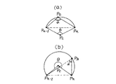
次に図9で円弧部分の両端と中心とを結ぶ角度で円弧側の角度をθ、円弧部分の両端と円弧上の一点とを結ぶ角度をαとし、まずαを余弦定理により求めると、
【数7】
【0038】
ここで、 円周角=(中心角)/2 の関係が成り立つから、θ=2(π−α)となる。
尚、α≧π/2 ならば小円弧(図9a参照(θ≦π))、α<π/2 ならば大円弧(図9b参照(θ>π))となる。
又、円弧PnPaPn−1の面積は、大小共に
Aarc=(θ− sinθ)r2/2 となる。
【0039】
更に、円弧の図心を求める。
図10において、図心G(Xg,Yg)が円の中心Pcから円弧の中心を通る中心線上で中心Pcからどれだけの距離Dgにあるかを先ず計算する。
小円弧のX軸への断面一次モーメントMxは
Mx = ∫∫ ydydx (領域:円弧)で求め、面積で割ることで、Dgを求める。
大円弧の場合は小円弧とバランスさせて求めると簡単である。
その結果
【0040】
【数8】
【0041】
続いて、円弧の図心Gと円の中心Pcとの距離Dgが上記のように求められた後、図心座標G(Xg,Yg)を求める前に、円弧輪郭上の回り方(右/左回り)を判定するために、円弧トレースの回転判別式Daを求める。
円弧輪郭上の回り方は、図12示に示したアーク三角形Cの面積の正負で判別することができる。
【0042】
即ち、アークの回転判別式Daは、アーク三角形Cの面積
Da=Xn−1( Ya−Yn)+Xa(Yn−Yn−1)+Xn(Yn−1−Ya)
で与えられ、
Da>0のとき ・・左回り
Da<0のとき ・・右回り
となる。また、円弧の弦の長さLaは、両端点(Xn−1,Yn−1)、(Xn,Yn)間の距離であるから、
La=Root{(Xn−1−Xn)2+(Yn−1−Yn)2}
となる。
【0043】
図心座標G(Xg,Yg)は、円弧輪郭上の回り方(右/左回り)によって、決まり、右回りのときは、
Xg=Xc−(Dg/La)(Yn−Yn−1)
Yg=Yc+(Dg/La)(Xn−Xn−1)
左回りのときは、
Xg=Xc+(Dg/La)(Yn−Yn−1)
Yg=Yc−(Dg/La)(Xn−Xn−1)
となる。
円弧のX,Y軸への断面一次モーメントをMx,My とすると
Mx =円弧面積×図心Yg=Aarc・Yg
My =Aarc・Xg
で求められる。
【0044】
次に、上記で求めた円弧の面積Aarc及び断面一次モーメントMx,Myを図12に示すように多角形について求めた面積Fn、断面一次モーメントTX,TYへの加算する方法について説明する。
【0045】
n多角形の面積Fnは、ステップ40においても示したように、
【数9】
そこで、再びアークの回転判別式Daを用いて、円弧のトレース方向が左回りか右回りかを判断する。
【0046】
Aarcは常に正値でしか計算出来ないので、アーク三角形Cの符号の正負を与える。
Da<0 ならば 新Aarc=−Aarc
Da≧0 ならば 新Aarc=Aarc
とおいて、
Fn=Fn+新Aarc
を求めることで、円弧部分を含む図形の全面積が得られる。尚、ここでアークは何個あっても良い。
Fnには正負があるので、最後の面積は|Fn|とする。
【0047】
n多角形の断面一次モーメントTY,TXは
【数10】
【0048】
即ち、
Da<0 (右回り円弧)ならば・・・・(4)
TY=TY+My
TX=TX+Mx
Da≧0 (左回り円弧)ならば・・・・(5)
TY=TY−My
TX=TX−Mx
となる。
【0049】
(4)、(5)をまとめると
Da<0ならば、
新My=My
新Mx=Mx
Da≧0ならば
新My=My×(−1)
新Mx=Mx×(−1)
となり、合計の断面一次モーメントは、
TY=TY+新My
TX=TX+新Mx
でまとめることができる。
【0050】
図形が閉合したとき
Fn>0 (左回り)ならば
TY=TY×(−1)
TX=TX×(−1)
とし、全面積TAは
TA=|Fn|
であるから、図心座標(TGx,TGy)は
TGx=TY/|Fn|
TGy=TX/|Fn|
となる(ステップ64参照)。
【0051】
なお、上述の説明は円弧部分を含む多角形の場合であるが、円弧部分を含む曲線輪郭の図形の場合でも、円弧部分の測定は上述の方法が適用出来ることは勿論である。
【0052】
【発明の効果】
上述のように、n多角形の図形でも曲線図形でも、一部に円弧部分がある場合は、その円弧部分に限って円弧の両端及びその中間の1点の座標値を入力することにより、円弧の面積や断面一次モーメント等の円弧部分に関する図形パラメータが算出されるので、n多角形又は曲線輪郭図形の図形パラメータに加算又は減算することによって、全図形のより正確な図形パラメータを求めることができ、また、その測定が極めて簡易化される。
【図面の簡単な説明】
【図1】本発明の図形測定装置の一例の平面図である。
【図2】直線輪郭の図形の図心測定の説明図である。
【図3】従来の直線輪郭の図形の図心算出の説明図である。
【図4】従来の曲線輪郭の図形の図心算出の説明図である。
【図5】従来の改良された図心測定の理論の説明図である。
【図6】従来の改良された図心測定の理論の説明図である。
【図7】従来の改良された図心測定のフローチャートである。
【図8】本発明の図心又は面積測定の際の円弧部分の説明図である。
【図9】円弧部分の説明図で、(a)は小円弧の場合、(b)は大円弧の場合である。
【図10】円弧部分の詳細説明図で、(a)は小円弧の場合、(b)は大円弧の場合である。
【図11】円弧部分の座標上の位置説明図である。
【図12】円弧部分を多角形に加算する説明図である。
【図13】本発明の装置の図心及び円弧面積を計算するフローチャートの一部である。
【図14】本発明の装置の図心及び円弧面積を計算するフローチャートの一部である。
【図15】本発明の装置の図心及び円弧面積を計算するフローチャートの一部である。
【図16】本発明の装置の図心及び円弧面積を計算するフローチャートの一部である。
【符号の説明】
1 本体
2 測桿
3 表示装置
4 入力装置
5 ローラー
6 トレース部
7 マーク針
8 アークキー(第2の座標入力手段)
9 ポイントキー(第1の座標入力手段)[0001]
TECHNICAL FIELD OF THE INVENTION
The present invention relates to a figure measuring apparatus for measuring figure parameters such as area, first moment of area, length, centroid coordinates, etc. of a plane figure by tracing along the contour of the plane figure.
[0002]
[Prior art]
Conventionally, in the case of a linear figure as shown in FIG. 3, the centroid is divided into triangles (abg, bgf, bfh) and rectangles (cdeh) including squares, and the first moment of area is individually calculated from each area and centroid. The centroid was calculated by calculating the sum, dividing the sum, and dividing by the area of the straight line figure (agfedchba).
[0003]
Further, in the case of a graphic having a curved contour as shown in FIG. 4, there has been no other method than to approximately divide the graphic into a large number of triangles and obtain the centroid by the above-described method.
However, in the case of a linear figure as shown in FIG. 3, an accurate centroid can be calculated, but as the number of sides increases, the amount of calculation work also increases, and a long time is required.
[0004]
In addition, since the method of FIG. 4 is originally an approximate method, it is difficult to expect accuracy, and it is necessary to divide the division in order to approach an accurate value. It is possible.
[0005]
In order to solve these problems, the present applicant has proposed a previously improved device, Japanese Patent Application No. 4-2008013. The
[0006]
The theory used in this conventional improved device will be described with reference to FIGS. 5 and 6 as examples. The first moment of area Mx with respect to the x-axis is given by
[0007]
The y coordinate of the centroid is divided by the area A of the area D and
Similarly, the x-coordinate of the centroid is
[0009]
Here, the first moment of area M x is given by:
[0010]
FIG. 7 is a flowchart showing specific processing by the calculating means of the centroid coordinate measuring device based on the above theory. Initially started (step 10) since the
Subsequently, it is determined whether the vertex is the last vertex (step 14). If it is the last vertex, since the measured figure is closed, it coincides with the first coordinates. Therefore, in
[0011]
It is determined again whether or not the vertex is the last vertex, that is, whether or not the figure has completed one round (step 20). If it is not the last vertex, P n-1 = P n is set (step 19), and
[0012]
Next, this calculation will be described in detail.
First, considering the case where the first moment of area to the x-axis is calculated for the n-polygon in FIG. 2, an element determined by two consecutive vertices P 1 (x 1 , y 1 ) and P 2 (x 2 , y 2 ) The primary moment of area My 1 of the trapezoid P 1 P 2 x 2 x 1 can be obtained by a method of dividing into two triangles P 1 P 2 x 1 and P 2 x 2 x 1 , and the result is expressed by the following equation. Given by
My 1 = (x 2 -x 1 ) (y 2 2 + y 2 y 1 + y 1 2) / 6
Similarly, trapezoidal P n-1 P n x n x n-1 in cross section the first moment My n of the (n-1) th side make the
My n = (x n -x n -1) (y n 2 + y n y n-1 + y n-1 2) / 6 ··· (1)
(See step 18). Note that this expression is for clockwise tracing, and the sign is inverted when tracing counterclockwise.
[0013]
Further, similarly cross the first moment Mx n to trapezoidal y-axis the (n-1) th side make the
Mx n = (y n-1 -y n) (
(See step 18). Note that this expression is for clockwise tracing, and the sign is inverted when tracing counterclockwise.
[0014]
Note that equation (1), the point at (2) P n (x n , y n) is consistent with the
[0015]
Here, the vertex P 1, P 2 of the figure, in order to trace the coordinates of · · P n,
(Equation 5)
[0016]
It is generally known that the area S of a target graphic is obtained by the following formula.
(Equation 6)
Therefore, by examining the sign of F, it is possible to determine in which direction the figure has been traced, and it is not necessary to limit the way of the trace.
Thus, by dividing the first moments of area My n , Mx n by the area F n of the n polygon, the centroid x coordinate and the centroid y coordinate are obtained (see step 26).
[0018]
[Problems to be solved by the invention]
However, in the case of a straight line figure as shown in FIGS. 2 and 3, it is possible to calculate the centroid of the entire figure only by measuring the coordinates of each vertex, but there are some arc-shaped sides. In a figure, there is a problem that at least the arc-shaped portion must be traced accurately.
It is an object of the present invention to provide an apparatus for accurately calculating a figure along an arc only by measuring the coordinates of three points at both ends and an intermediate point on the arc.
[0019]
[Means for Solving the Problems]
According to an aspect of the present invention, there is provided a body having rollers capable of traveling in a straight line,
A measuring rod that is pivotally supported by the main body so as to be rotatable in the horizontal direction on a horizontal plane with respect to the running direction of the main body, and that has a trace portion on the tip end side;
First coordinate input means for sequentially inputting the coordinate value of the current position of the trace portion positioned on a point on the contour of the figure;
Calculating means for sequentially calculating graphic parameters of the measured graphic using coordinate values sequentially input from the first coordinate input means and calculating a total of the graphic parameters;
In the figure measuring device provided with
A second coordinate input unit for inputting a coordinate value of a current position of the trace unit positioned at an arbitrary intermediate point on an outline of an arc portion of the figure;
The calculating means calculates a graphic parameter relating to the arc portion from coordinates of three points, ie, an intermediate point input by the second coordinate input means and both end points of the arc portion input by the first coordinate input means. In addition, a figure parameter relating to the arc portion is added or subtracted from a figure parameter of a measured figure calculated using coordinate values sequentially input from the first coordinate input means.
[0020]
According to a second aspect of the present invention, in the first aspect, the graphic parameters of the measured graphic are an area and a first moment of area,
The calculating means calculates the area and the first moment of area of the element defined by the coordinates of two adjacent points sequentially input by the first coordinate input means, and finally calculates the total area by the total area of the measured figures. When the coordinates are input in the order of the first coordinate input means, the second coordinate input means, and the first coordinate input means, the input is performed. The first point and the end point of the three points are set at both ends, the area and the first moment of area of the arc portion passing through the intermediate point are calculated, and the coordinates of two adjacent points sequentially inputted by the first coordinate input means are calculated. The area and the primary moment of area of the arc portion are respectively added to or subtracted from the area and primary moment of area of the element defined by
[0021]
According to a third aspect of the present invention, in the second aspect, the calculating means is configured such that a moving direction for measuring a point on the contour of the figure and a moving direction of the three measuring points of the arc are the same. In the case of the above, the area of the arc portion defined by the three points is added to the area of the element defined by the coordinates of two adjacent points sequentially input by the first coordinate input means, and the reverse direction is obtained. In the above case, the area of the arc defined by the three points is subtracted from the area of an element defined by the coordinates of two adjacent points sequentially input by the first coordinate input means. .
[0022]
According to a fourth aspect of the present invention, in the device according to any one of the first to third aspects, the stick has a mark needle provided near the trace portion, and the figure measuring device further comprises: A display device for displaying a difference between the coordinates of the current position of the mark hand and the centroid coordinates calculated by the calculation means is provided.
[0023]
In an actual drawing, since a region is hardly represented by a function, the coordinate value of each point is determined by moving the trace portion along the contour of the figure by the apparatus according to the present invention while dividing the figure outline into minute sections. Then, the first moment of area and the area are sequentially calculated to obtain the first moment of area and the total area. At the end of the figure measurement, the centroid is calculated by dividing the total value of the first moment of area by the total area of the figure.
In this case, for the arc portion, by inputting the coordinates of both ends and the intermediate point of the arc, the area or the primary moment of area of the arc portion is automatically calculated and added to or subtracted from the entire figure.
[0024]
Therefore, it is not necessary to trace the outline of the figure with respect to the arc part, and the calculating means can calculate the figure parameters such as the area of the arc part only by measuring the coordinates of the start point, the end point, and the intermediate point of the arc part. Also, if the moving direction of each measurement point of the figure body and the moving direction of the three points of the circular arc are the same, add to the area of the polygon connecting the circular arc with a straight line, and subtract in the opposite direction. By doing so, an accurate total area is required. Calculation of the centroid can also be simplified.
[0025]
BEST MODE FOR CARRYING OUT THE INVENTION
FIG. 1 is a plan view of a figure measuring apparatus according to the present invention, which is almost the same as a conventional improved centroid or figure measuring apparatus. A point key 9 (first coordinate) which is pivotally supported by the
[0026]
Further, the figure measuring apparatus of the present invention is provided with an arc key 8 (second coordinate input means) on a part of the measuring
[0027]
The measurement according to the flowchart shown in FIG. 7 can accurately determine the centroid in the case of an n-polygon, but if at least one of the n sides has an arc portion, the obtained centroid is inaccurate. Become. Therefore, the calculation means of the apparatus of the present invention performs the processing according to the following flowchart, which can be accurately obtained even in such a case.
[0028]
FIGS. 13 to 16 are flowcharts describing the processing of the calculating means for accurately calculating the centroid coordinates (TGx, TGy) of a figure partially or wholly composed of an arc contour. Since this flowchart is enormous from the start to the end, it is divided into FIGS. 13 to 16, and the
[0029]
Figure 13 shows the reached
Subsequently, it is determined whether the vertex is the last vertex (step 34). If it is the last vertex, since the measured figure is closed, it coincides with the first coordinate. Therefore, in
[0030]
If not a point on the arc at
[0031]
Next, as shown in FIG. 14, at step 42, it is determined whether or not the previous point is a point on the circular arc. In step 44, the midpoint of the arc (the arc point (X a, Y a)) and its two end points (X n-1, Y n -1), a (X n, Y n) coordinate of the three consecutive points The attribute radius r of the arc, the center Pc of the arc Pc (Xc, Yc), the center angle θ of the arc, the arc area A arc , etc. are calculated, and in the next step 46 the diagram of the arc from the center Pc of the arc is calculated. distance D g to mind P g, rotary discriminant D a circular arc tracing, calculating the length L a of the arc chord.
[0032]
In
[0033]
It is determined again whether or not the vertex is the last vertex, that is, whether or not the figure has completed one round (step 60). If it is not the last vertex, P n-1 = P n is set (step 61), and step 32 is performed again. Returning to step 60, if it is the last vertex, it is determined in
[0034]
Next, the calculation of the above-described flowchart will be described in detail.
8 is an explanatory view of the shape of the arc portion, when the vertices of
[0035]
In this case, the moving direction of the measuring point at the coordinate position of each vertex of the polygon (including the curved figure) body is the same as the moving direction of the three points (start point, intermediate point, and end point) of the circular arc shown in FIG. It should be noted that the sign in the following explanatory formula changes between the case of the direction and the case of the reverse direction.
[0036]
When the coordinate values of the above three points, P n , P a , and P n−1 , are determined, the equation of the circle becomes the center P c of the circle.
( Xc , Yc ) and the radius is r,
(XX c ) 2 + (Y−Y c ) 2 = r 2 (3)
Therefore, the center P c (X c , Y c ) and the radius r can be obtained by solving a simultaneous equation using the coordinate values of the three points P n , P a , and P n-1 (the equation in step 44). reference).
[0037]
Next, in FIG. 9, the angle between the both ends of the arc portion and the center is the angle on the arc side, and the angle between the both ends of the arc portion and one point on the arc is α. First, α is obtained by the cosine theorem.
(Equation 7)
[0038]
Here, since the relationship of circumferential angle = (center angle) / 2 holds, θ = 2 (π−α).
Note that if α ≧ π / 2, a small arc (see FIG. 9A (θ ≦ π)), and if α <π / 2, a large arc (see FIG. 9b (θ> π)).
Also, the area of the circular arc P n P a P n-1 becomes A arc = (θ- sinθ) r 2/2 in magnitude both.
[0039]
Further, the centroid of the arc is obtained.
10, the centroid G (X g, Y g) Do the first calculated from the center P c at the center line passing through the arc center to center P c of the circle to how much distance D g.
Section first moment Mx to small circular arc of the X-axis is Mx = ∫∫ ydydx: calculated by (area arc), by dividing the area, obtaining the D g.
In the case of a large arc, it is easy to find a balance with a small arc.
As a result,
(Equation 8)
[0041]
Subsequently, the distance D g between the center P c of the arc of centroid G and the circle was determined as described above, the centroid coordinates G (X g, Y g) before seeking, around on the arc contour to determine the square (right / left-handed), and determines a rotation discriminant D a circular arc trace.
The direction of rotation on the circular arc contour can be determined by the sign of the area of the arc triangle C shown in FIG.
[0042]
That is, the rotation discriminant D a of the arc, the area of the arc triangle C D a = X n-1 (Y a -Y n) + X a (Y n -Y n-1) + X n (Y n-1 -Y a )
Given by
When D a > 0: When counterclockwise D a <0: When clockwise. Further, the length L a of the arc chord, both end points (X n-1, Y n -1), since the distance between (X n, Y n),
L a = Root {(X n -1 -X n) 2 + (Y n-1 -Y n) 2}
It becomes.
[0043]
The centroid coordinates G (X g , Y g ) are determined by the direction of rotation (right / left) on the circular arc contour.
X g = X c - (D g / L a) (Y n -Y n-1)
Y g = Y c + (D g / L a) (X n -X n-1)
When counterclockwise,
X g = X c + (D g / L a) (Y n -Y n-1)
Y g = Y c - (D g / L a) (X n -X n-1)
It becomes.
Assuming that the first moments of area of the arc along the X and Y axes are Mx and My, Mx = arc area × centroid Y g = A arc · Y g
My = A arc · X g
Is required.
[0044]
Next, a method of adding the area A arc of the arc and the primary moments of area Mx and My obtained above to the area F n and the primary moments of area TX and TY of the polygon as shown in FIG. 12 will be described.
[0045]
area F n of n polygons, as also shown in
(Equation 9)
Therefore, again using a rotary discriminant D a of the arc, arc tracing direction is determined whether left-handed or right-handed.
[0046]
Since A arc can always be calculated only with a positive value, the sign of the arc triangle C is given.
If D a <0, new A arc = -A arc
If D a ≧ 0, new A arc = A arc
And then
F n = F n + new A arc
Is obtained, the total area of the figure including the arc portion can be obtained. Here, there may be any number of arcs.
Since the F n is negative, the last of the area | F n | to.
[0047]
The first moment of area TY, TX of the n-polygon is given by
[0048]
That is,
If D a <0 (clockwise arc) ... (4)
TY = TY + My
TX = TX + Mx
If D a ≥ 0 (counterclockwise arc) ... (5)
TY = TY−My
TX = TX−Mx
It becomes.
[0049]
Summarizing (4) and (5), if D a <0,
New My = My
New Mx = Mx
If D a ≧ 0, new My = My × (−1)
New Mx = Mx × (-1)
And the total first moment of area is
TY = TY + New My
TX = TX + new Mx
Can be put together.
[0050]
If F n > 0 (counterclockwise) when the figures are closed, TY = TY × (−1)
TX = TX × (−1)
And the total area TA is TA = | F n |
Since it is, the centroid coordinates (TGx, TGY) is TGx = TY / | F n |
TGy = TX / | F n |
(See step 64).
[0051]
In the above description, a polygon including an arc portion is described. However, even in the case of a figure having a curved contour including an arc portion, the above method can be applied to the measurement of the arc portion.
[0052]
【The invention's effect】
As described above, if there is an arc portion in either the n-polygonal graphic or the curved graphic, the coordinate values of both ends of the arc and one intermediate point are input only to the arc portion, thereby obtaining the arc. Since the figure parameters related to the arc portion such as the area and the first moment of area are calculated, more accurate figure parameters of all figures can be obtained by adding or subtracting to or from the figure parameters of the n polygon or curved contour figure. Also, the measurement is greatly simplified.
[Brief description of the drawings]
FIG. 1 is a plan view of an example of a figure measuring apparatus according to the present invention.
FIG. 2 is an explanatory diagram of centroid measurement of a figure having a straight contour.
FIG. 3 is an explanatory diagram of conventional centroid calculation of a figure having a straight contour.
FIG. 4 is an explanatory diagram of conventional centroid calculation of a figure having a curved contour.
FIG. 5 is an explanatory diagram of a conventional improved centroid measurement theory.
FIG. 6 is an explanatory diagram of a conventional improved centroid measurement theory.
FIG. 7 is a flowchart of a conventional improved centroid measurement.
FIG. 8 is an explanatory view of an arc portion at the time of centroid or area measurement according to the present invention.
9A and 9B are explanatory diagrams of an arc portion, where FIG. 9A shows a case of a small arc and FIG. 9B shows a case of a large arc.
FIG. 10 is a detailed explanatory view of an arc portion, where (a) shows a case of a small arc and (b) shows a case of a large arc.
FIG. 11 is an explanatory diagram of a position on a coordinate of an arc portion.
FIG. 12 is an explanatory diagram of adding a circular arc portion to a polygon.
FIG. 13 is a part of a flowchart for calculating the centroid and the arc area of the apparatus of the present invention.
FIG. 14 is a part of a flowchart for calculating the centroid and the arc area of the apparatus of the present invention.
FIG. 15 is a part of a flowchart for calculating the centroid and the arc area of the apparatus of the present invention.
FIG. 16 is a part of a flowchart for calculating the centroid and the arc area of the apparatus of the present invention.
[Explanation of symbols]
DESCRIPTION OF
9 Point keys (first coordinate input means)
Claims (4)
この本体の走行方向に対して水平面上で左右方向に回動可能に本体に枢支され、かつ先端側にトレース部を具備した測桿と、
図形の輪郭上の点上に位置づけられる前記トレース部の現在位置の座標値を逐次入力するための第1の座標入力手段と、
前記第1の座標入力手段から逐次入力される座標値を用いて測定図形の図形パラメータを逐次算出すると共にその図形パラメータの合計を算出する計算手段と、
を設けた図形測定装置において、
図形の円弧部分の輪郭上の任意の中間点に位置づけられた前記トレース部の現在位置の座標値を入力するための第2の座標入力手段をさらに備え、
前記計算手段は、前記第2の座標入力手段によって入力される中間点と前記第1の座標入力手段によって入力される円弧部分の両端点の3点の座標からその円弧部分に関する図形パラメータを算出すると共に、前記第1の座標入力手段から逐次入力される座標値を用いて算出した測定図形の図形パラメータに、前記円弧部分に関する図形パラメータを加算または減算する、ことを特徴とする図形測定装置。A body provided with rollers that can travel in a straight line,
A measuring rod that is pivotally supported by the main body so as to be rotatable in the horizontal direction on a horizontal plane with respect to the running direction of the main body, and that has a trace portion on the tip end side;
First coordinate input means for sequentially inputting the coordinate value of the current position of the trace portion positioned on a point on the contour of the figure;
Calculating means for sequentially calculating graphic parameters of the measured graphic using coordinate values sequentially input from the first coordinate input means and calculating a total of the graphic parameters;
In the figure measuring device provided with
A second coordinate input unit for inputting a coordinate value of a current position of the trace unit positioned at an arbitrary intermediate point on an outline of an arc portion of the figure;
The calculating means calculates a graphic parameter relating to the arc portion from coordinates of three points, ie, an intermediate point input by the second coordinate input means and both end points of the arc portion input by the first coordinate input means. And a graphic parameter relating to the arc portion is added to or subtracted from a graphic parameter of a measured graphic calculated using coordinate values sequentially inputted from the first coordinate input means.
前記計算手段は、前記第1の座標入力手段により逐次入力される隣接された2点の座標によって画成される要素の面積及び断面一次モーメントを算出し、最後に測定図形の合計の面積で合計の断面一次モーメントを割算して図心座標を算出すると共に、前記第1の座標入力手段、第2の座標入力手段及び第1の座標入力手段の順で座標が入力された場合に、入力された3点の初点及び終点を両端とし、中間点を通過する円弧部分の面積及び断面一次モーメントを算出して、前記第1の座標入力手段により逐次入力される隣接された2点の座標によって画成される要素の面積及び断面一次モーメントに、前記円弧部分の面積及び断面一次モーメントをそれぞれ加算または減算する、ことを特徴とする請求項1記載の図形測定装置。The figure parameters are area and area first moment,
The calculating means calculates the area and the first moment of area of the element defined by the coordinates of two adjacent points sequentially input by the first coordinate input means, and finally calculates the total area by the total area of the measured figures. When the coordinates are input in the order of the first coordinate input means, the second coordinate input means, and the first coordinate input means, the input is performed. The first point and the end point of the three points are set at both ends, the area and the first moment of area of the arc portion passing through the intermediate point are calculated, and the coordinates of two adjacent points sequentially inputted by the first coordinate input means are calculated. The figure measuring apparatus according to claim 1, wherein an area and a primary moment of area of the arc portion are respectively added to or subtracted from an area and a primary moment of area defined by the element.
Priority Applications (1)
| Application Number | Priority Date | Filing Date | Title |
|---|---|---|---|
| JP13201096A JP3546112B2 (en) | 1995-05-31 | 1996-05-27 | Figure measuring device |
Applications Claiming Priority (3)
| Application Number | Priority Date | Filing Date | Title |
|---|---|---|---|
| JP7-133863 | 1995-05-31 | ||
| JP13386395 | 1995-05-31 | ||
| JP13201096A JP3546112B2 (en) | 1995-05-31 | 1996-05-27 | Figure measuring device |
Publications (2)
| Publication Number | Publication Date |
|---|---|
| JPH0949724A JPH0949724A (en) | 1997-02-18 |
| JP3546112B2 true JP3546112B2 (en) | 2004-07-21 |
Family
ID=26466684
Family Applications (1)
| Application Number | Title | Priority Date | Filing Date |
|---|---|---|---|
| JP13201096A Expired - Fee Related JP3546112B2 (en) | 1995-05-31 | 1996-05-27 | Figure measuring device |
Country Status (1)
| Country | Link |
|---|---|
| JP (1) | JP3546112B2 (en) |
-
1996
- 1996-05-27 JP JP13201096A patent/JP3546112B2/en not_active Expired - Fee Related
Also Published As
| Publication number | Publication date |
|---|---|
| JPH0949724A (en) | 1997-02-18 |
Similar Documents
| Publication | Publication Date | Title |
|---|---|---|
| US11934743B2 (en) | Method for measuring the surface shape of a toric mirror | |
| JP3057960B2 (en) | Evaluation equipment for three-dimensional workpieces | |
| CN103340632A (en) | Human joint angle measuring method based on feature point space position | |
| CN106355598A (en) | Automatic wrist and finger joint motion degree measurement method | |
| Martin | Estimation of principal curvatures from range data | |
| JPH032509A (en) | Measuring instrument for coordinate arithmetic figure | |
| CN117671161B (en) | Method for finely calculating concrete volume among different working procedures of tunnel and storage medium | |
| CN116644532A (en) | Method for evaluating contact spots of gear pair | |
| KR100218218B1 (en) | Shape measuring device | |
| EP0664434B1 (en) | Device for finding centroid coordinates of figures | |
| JPH0949724A (en) | Figure measuring device | |
| JP6668986B2 (en) | Inter-plane distance measuring method, inter-plane distance calculating device and distance measuring device | |
| JP3764856B2 (en) | Method for evaluating the shape failure of the surface to be measured | |
| CN1065047C (en) | Curved surface shape measuring method | |
| JPH07294241A (en) | Inner / outer length measuring instrument | |
| JPH0658702A (en) | Centroid coordinate measuring device | |
| JPH07318301A (en) | Method and apparatus for measuring uneven thickness of cylindrical body | |
| US3220115A (en) | Sine wave template | |
| CN206724853U (en) | One kind calculates disk | |
| KR200255158Y1 (en) | a improved graduator | |
| JP3009767U (en) | Difference with scale for protractor | |
| JPS5937896Y2 (en) | Curvature radius measurement ruler | |
| Cloud et al. | Real-time digital speckle interferometry to measure crack length | |
| JPH07138993A (en) | Method for measuring excavation position of power shovel and excavation position display device used in the measurement method | |
| JP2017211757A (en) | Device for displaying curvature distribution of three-dimensional surface shape |
Legal Events
| Date | Code | Title | Description |
|---|---|---|---|
| TRDD | Decision of grant or rejection written | ||
| A01 | Written decision to grant a patent or to grant a registration (utility model) |
Free format text: JAPANESE INTERMEDIATE CODE: A01 Effective date: 20040406 |
|
| A61 | First payment of annual fees (during grant procedure) |
Free format text: JAPANESE INTERMEDIATE CODE: A61 Effective date: 20040412 |
|
| R150 | Certificate of patent or registration of utility model |
Free format text: JAPANESE INTERMEDIATE CODE: R150 |
|
| R250 | Receipt of annual fees |
Free format text: JAPANESE INTERMEDIATE CODE: R250 |
|
| FPAY | Renewal fee payment (event date is renewal date of database) |
Free format text: PAYMENT UNTIL: 20090416 Year of fee payment: 5 |
|
| FPAY | Renewal fee payment (event date is renewal date of database) |
Free format text: PAYMENT UNTIL: 20100416 Year of fee payment: 6 |
|
| LAPS | Cancellation because of no payment of annual fees |