JP3632002B2 - Method and apparatus for producing curved extruded profiles - Google Patents
Method and apparatus for producing curved extruded profiles Download PDFInfo
- Publication number
- JP3632002B2 JP3632002B2 JP2001557707A JP2001557707A JP3632002B2 JP 3632002 B2 JP3632002 B2 JP 3632002B2 JP 2001557707 A JP2001557707 A JP 2001557707A JP 2001557707 A JP2001557707 A JP 2001557707A JP 3632002 B2 JP3632002 B2 JP 3632002B2
- Authority
- JP
- Japan
- Prior art keywords
- die
- billet
- discharge direction
- extrusion
- mandrel
- Prior art date
- Legal status (The legal status is an assumption and is not a legal conclusion. Google has not performed a legal analysis and makes no representation as to the accuracy of the status listed.)
- Expired - Fee Related
Links
Images


Classifications
-
- B—PERFORMING OPERATIONS; TRANSPORTING
- B21—MECHANICAL METAL-WORKING WITHOUT ESSENTIALLY REMOVING MATERIAL; PUNCHING METAL
- B21C—MANUFACTURE OF METAL SHEETS, WIRE, RODS, TUBES, PROFILES OR LIKE SEMI-MANUFACTURED PRODUCTS OTHERWISE THAN BY ROLLING; AUXILIARY OPERATIONS USED IN CONNECTION WITH METAL-WORKING WITHOUT ESSENTIALLY REMOVING MATERIAL
- B21C23/00—Extruding metal; Impact extrusion
- B21C23/02—Making uncoated products
- B21C23/04—Making uncoated products by direct extrusion
- B21C23/08—Making wire, rods or tubes
- B21C23/12—Extruding bent tubes or rods
-
- B—PERFORMING OPERATIONS; TRANSPORTING
- B21—MECHANICAL METAL-WORKING WITHOUT ESSENTIALLY REMOVING MATERIAL; PUNCHING METAL
- B21C—MANUFACTURE OF METAL SHEETS, WIRE, RODS, TUBES, PROFILES OR LIKE SEMI-MANUFACTURED PRODUCTS OTHERWISE THAN BY ROLLING; AUXILIARY OPERATIONS USED IN CONNECTION WITH METAL-WORKING WITHOUT ESSENTIALLY REMOVING MATERIAL
- B21C25/00—Profiling tools for metal extruding
- B21C25/02—Dies
Landscapes
- Engineering & Computer Science (AREA)
- Mechanical Engineering (AREA)
- Extrusion Of Metal (AREA)
- Extrusion Moulding Of Plastics Or The Like (AREA)
- Press-Shaping Or Shaping Using Conveyers (AREA)
- Casting Or Compression Moulding Of Plastics Or The Like (AREA)
Abstract
Description
【0001】
この発明は、ワークピースを押型内で形成しこれを押出成形装置から吐出することによって湾曲したワークピースを製造する方法ならびに装置に関する。
【0002】
湾曲したアルミニウム形材は、特にレール、道路、飛行機製造等の多様な技術分野において使用される。従来このワークピースは、直線的な押出成形の後伸延曲げ加工によって仕上げられていた。
【0003】
この方法を改良したものは、所要の最終的な形状を実質的に押出と同時に曲げ加工することによって形成するものである(欧州特許第0706843A1号公報参照)。この際、従来の押出成形によって処理され、通常押型を支持するための小さな開口部を有するオーバアームとしてトップビームを使用している。
【0004】
押出形材を曲げ加工する際に圧搾器具によって丸み付けされる場合、押出口の形によって成形するものの最低半径が制限される。そうでないとビレットと圧搾機との衝突が生じる。その結果製品の多様性が大幅に制限されてしまう。
【0005】
従って、本発明の目的は、可能な限り低いコストでより小さな半径をもって押出成形品の曲げ加工を達成し、その結果製造される製品の範囲を拡大することである。
【0006】
前記の課題は、本発明に係る方法に従って、押型から吐出される際曲げ加工の前にビレット吐出方向(A)が後のワークピースの湾曲と逆側の斜め前方に延在するように押出形材を転向させることによって解決される。圧搾器具から吐出されたビレットは続く曲げ加工によって別の側に著しく強く湾曲するように方向付けられている。
【0007】
本発明に係る湾曲したワークピースを製造するための押出成形装置は器具ホルダを備えており、その収容開口部内に心棒付または心棒無の押型および遮蔽蓋材からなる圧搾器具セットが配置され、吐出されるビレットを形成する押型および/または心棒のガイド面がビレット吐出方向に対応して斜めに構成または配置され、ビレット吐出方向が押型の中央軸に対して後のワークピースの湾曲方向とは逆側に所定の入射角を有する。
【0008】
他方、ビレット吐出方向の変更は、
− 押型および場合によって心棒のガイド面の傾斜状態、
− 設計変更された器具ホルダ内への従来の圧搾器具の取付け、および/または、
− 従来の器具ホルダ内への斜めに平面化した圧搾器具の取付け
によって達成することができる。
【0009】
以下に従来の圧搾器具セット(図1)を説明するとともに、複数の実施例によって本発明を説明する。図2ないし図4の断面図は、湾曲した押出形材を製造するためのそれぞれ異なった解決方式を示している。
【0010】
従来の圧搾器具セットは、押型1、心棒4を有する心棒部2、および心棒4と押型1との間の両側のガイド面3とからなる。矢印Aは押出形材の吐出方向を示しており、これは従来の押出成形機(図1)においては押型1の中央軸Mと重なっている。
【0011】
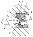
本発明の基本概念は、中央軸Mに対してビレット吐出方向Aを後のワークピースの湾曲とは逆側に入射角Sをもって斜めに設定することであり、これは異なった方式で達成することができる。図2の断面図において押型1および心棒4のガイド面3は押型1の中央軸Mに対して斜めに延在している。従って、図2内の矢印Aは所要の傾斜したビレット吐出方向を示しており、これは後のワークピースW(図3に点線で示されている)の湾曲と逆側に延在している。斜めのガイド面3は心棒側において心棒4を適宜に形成するかあるいはこれを斜めに配置することによって達成される。
【0012】
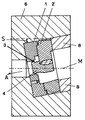
図3には、本発明に係る湾曲した押出形材を製造するための別の解決方式が示されている。これにおいては、従来の器具ホルダ内に押型1と心棒2とからなる改変された圧搾器具が示されている。この改変は、圧搾器具が周囲側に入射角Sに従って傾斜した平滑面を備え、従ってこれはくさび形の背部材7を介して器具ホルダ6の収容開口部9内に斜めに挿入することができる。これに対応して傾斜化された遮蔽部材8も心棒部分2を支持するために開口部9内に挿入されることは勿論であり、これによって圧搾器具に作用する力が器具ホルダ6内において受容される。
【0013】
図4に示された本発明の基本概念は、器具ホルダ6内に斜めに形成された収容開口部9の中に従来式の圧搾器具を挿入する押出成形装置である。この圧搾器具は従来式の遮蔽部材8によって支持され、これは押型1と心棒部分2とを器具ホルダ6内を斜めに延在する収容開口部9の先端部に対して押圧している。必要であれば前述した構成形態との組合せを選択することもでき、この際例えば斜めのガイド面3を入射角Sをもって斜めに挿入された圧搾器具と組合わせるか、または傾斜して平滑化された押型1あるいは心棒部分2の周囲側を斜めに延在する収容開口部9と組合わせることができる。この際ビレット吐出方向Aが後のワークピースの湾曲と逆側に斜めに延在するよう常に留意する必要がある。
【図面の簡単な説明】
【図1】従来の技術水準に従った圧搾器具を示す断面図である。
【図2】本発明に従って斜めのガイド面および斜めに配置された心棒によって構成された押出成形装置を示す断面図である。
【図3】本発明に従って従来の器具ホルダ内に斜めの圧搾器具を設けて構成された押出成形装置を示す断面図である。
【図4】本発明に従って斜めに形成された器具ホルダならびに従来の圧搾器具を設けて構成された押出成形装置を示す断面図である。[0001]
The present invention relates to a method and an apparatus for manufacturing a curved workpiece by forming a workpiece in a die and discharging it from an extrusion molding apparatus.
[0002]
Curved aluminum profiles are used in various technical fields such as rails, roads, airplane manufacturing, among others. Traditionally, this workpiece has been finished by linear extrusion and then by extension bending.
[0003]
An improvement of this method is that the required final shape is formed by bending at substantially the same time as extrusion (see EP 0 706 443 A1). In this case, the top beam is used as an overarm that is processed by conventional extrusion and usually has a small opening for supporting the die.
[0004]
When the extruded shape is rounded by a squeezing tool when bending, the minimum radius of what is formed is limited by the shape of the extrusion opening. Otherwise, there will be a collision between the billet and the press. As a result, the diversity of products is greatly limited.
[0005]
The object of the present invention is therefore to achieve the bending of extruded products with a smaller radius at the lowest possible cost and consequently to expand the range of products produced.
[0006]
According to the method of the present invention, the above-described problem is that the extrusion shape is such that the billet discharge direction (A) extends obliquely forward on the opposite side to the curve of the subsequent workpiece before bending when discharged from the die. It is solved by turning the material. The billet discharged from the squeezing device is oriented to be significantly strongly curved to the other side by the subsequent bending process.
[0007]
An extrusion molding apparatus for manufacturing a curved workpiece according to the present invention includes a tool holder, and a pressing tool set made of a pressing die with a mandrel or without a mandrel and a shielding lid member is disposed in the housing opening, and is discharged. The guide surface of the stamping die and / or mandrel forming the billet to be formed is constructed or arranged obliquely corresponding to the billet discharge direction, and the billet discharge direction is opposite to the curve direction of the subsequent workpiece with respect to the center axis of the stamping die It has a predetermined incident angle on the side.
[0008]
On the other hand, the change of billet discharge direction is
-The inclined state of the guide and possibly the guide surface of the mandrel,
-Installation of a conventional squeezing device in a redesigned device holder, and / or
-It can be achieved by mounting an obliquely flattened squeezing instrument in a conventional instrument holder.
[0009]
The conventional pressing device set (FIG. 1) will be described below, and the present invention will be described with reference to a plurality of embodiments. 2 to 4 show different solutions for producing curved extruded profiles.
[0010]
The conventional squeezing instrument set includes a
[0011]
The basic concept of the present invention is to set the billet discharge direction A obliquely with the incident angle S on the opposite side to the curvature of the subsequent workpiece with respect to the central axis M, which is achieved in a different manner. Can do. In the cross-sectional view of FIG. 2, the
[0012]
FIG. 3 shows another solution for producing a curved extruded profile according to the invention. In this, a modified squeezing tool consisting of a
[0013]
The basic concept of the present invention shown in FIG. 4 is an extrusion apparatus for inserting a conventional squeezing device into a
[Brief description of the drawings]
FIG. 1 is a cross-sectional view showing a pressing device according to the prior art.
FIG. 2 is a cross-sectional view showing an extrusion molding apparatus constituted by an oblique guide surface and an obliquely disposed mandrel according to the present invention.
FIG. 3 is a cross-sectional view illustrating an extrusion molding apparatus configured by providing an oblique pressing device in a conventional device holder according to the present invention.
FIG. 4 is a cross-sectional view showing an extrusion molding apparatus provided with a tool holder formed obliquely according to the present invention and a conventional pressing tool.
Claims (5)
押型(1)から吐出する際曲げ加工の前にビレット吐出方向(A)が後のワークピースの湾曲と逆側の斜め前方に延在するように押出形材を転向させることを特徴とする押出成形方法。It is a method of manufacturing a curved workpiece that is formed by extrusion in an extrusion die (1) of an extrusion molding apparatus and is then bent by the action of external stress after being discharged in the billet discharge direction.
Extrusion characterized in that the extruded shape is turned so that the billet discharge direction (A) extends obliquely forward on the opposite side to the curve of the subsequent workpiece before bending when discharging from the mold (1). Molding method.
吐出されるビレットを形成する押型(1)および/または心棒(4)のガイド面(3)がビレット吐出方向(A)に対応して斜めに構成または配置され、ビレット吐出方向が押型(1)の中央軸(M)に対して後のワークピースの湾曲方向とは逆側に所定の入射角(S)をもって延在することを特徴とする押出成形装置。A curved workpiece is produced, comprising a tool holder (6), in which a pressing tool set consisting of a pressing die (1) with or without a mandrel (4) and a shielding lid (8) is arranged in its receiving opening. An extrusion molding device for
The stamping die (1) for forming the billet to be discharged and / or the guide surface (3) of the mandrel (4) is configured or arranged obliquely corresponding to the billet discharging direction (A), and the billet discharging direction is the stamping die (1). An extruding apparatus characterized by extending with a predetermined incident angle (S) on the opposite side to the bending direction of the subsequent workpiece with respect to the central axis (M).
Applications Claiming Priority (3)
| Application Number | Priority Date | Filing Date | Title |
|---|---|---|---|
| DE10005903 | 2000-02-10 | ||
| DE10005903.1 | 2000-02-10 | ||
| PCT/EP2001/001415 WO2001058613A1 (en) | 2000-02-10 | 2001-02-09 | Method and device for producing curved extruded profiles |
Publications (2)
| Publication Number | Publication Date |
|---|---|
| JP2003522025A JP2003522025A (en) | 2003-07-22 |
| JP3632002B2 true JP3632002B2 (en) | 2005-03-23 |
Family
ID=7630457
Family Applications (1)
| Application Number | Title | Priority Date | Filing Date |
|---|---|---|---|
| JP2001557707A Expired - Fee Related JP3632002B2 (en) | 2000-02-10 | 2001-02-09 | Method and apparatus for producing curved extruded profiles |
Country Status (11)
| Country | Link |
|---|---|
| US (1) | US6634200B2 (en) |
| EP (1) | EP1169146B1 (en) |
| JP (1) | JP3632002B2 (en) |
| AT (1) | ATE265902T1 (en) |
| CA (1) | CA2366497A1 (en) |
| DE (1) | DE50102182D1 (en) |
| DK (1) | DK1169146T3 (en) |
| ES (1) | ES2220719T3 (en) |
| NO (1) | NO318742B1 (en) |
| TW (1) | TW558458B (en) |
| WO (1) | WO2001058613A1 (en) |
Families Citing this family (7)
| Publication number | Priority date | Publication date | Assignee | Title |
|---|---|---|---|---|
| DE10110035B4 (en) * | 2001-03-02 | 2005-05-04 | Sms Eumuco Gmbh | Outfeed device of an extrusion press |
| DE10236299A1 (en) * | 2002-08-08 | 2004-02-19 | Sms Eumuco Gmbh | Extrusion press esp. for fabrication of curved products has two-part tool located in counter part for simpler bending |
| DE10311169A1 (en) * | 2003-03-12 | 2004-09-23 | Sms Eumuco Gmbh | Arrangement for extruding curved extruded profiles has rotary table arranged in press output to receive curved profiles, shape in mold arranged, bent by external forces and cut into sub-lengths |
| DE10329696B3 (en) | 2003-07-02 | 2005-03-03 | WKW Erbslöh Automotive GmbH | Method for producing a plurality of curved extruded profiles |
| DE10329697B3 (en) * | 2003-07-02 | 2005-01-20 | WKW Erbslöh Automotive GmbH | Method for producing curved workpieces by extrusion and rounding |
| DE10340772A1 (en) * | 2003-09-02 | 2005-03-24 | Sms Eumuco Gmbh | Method and device for extruding curved extruded profiles |
| CN101905249B (en) * | 2010-07-30 | 2012-01-04 | 长沙仲腾金属材料科技有限公司 | Method and device for machining curved profiles in combination with online quenching temperature control in short flow |
Family Cites Families (10)
| Publication number | Priority date | Publication date | Assignee | Title |
|---|---|---|---|---|
| US1789675A (en) * | 1927-02-09 | 1931-01-20 | Ig Farbenindustrie Ag | Die extrusion method and apparatus |
| US2738873A (en) * | 1953-12-22 | 1956-03-20 | Schloemann Ag | Manufacture of practically endless extrusion products |
| JPS5641013A (en) * | 1979-09-11 | 1981-04-17 | Toyota Motor Corp | Method and apparatus for straightening bend of extruded product |
| DE2943960C2 (en) * | 1979-10-31 | 1985-03-21 | Christian Zürich Ragettli | Device for producing a pipe bend |
| JPS58184012A (en) * | 1982-04-21 | 1983-10-27 | Sankyo Alum Ind Co Ltd | Manufacture of curved profile |
| US4906171A (en) * | 1988-06-17 | 1990-03-06 | Gencorp Inc. | Directed flow die assembly |
| NL9200138A (en) * | 1992-01-24 | 1993-08-16 | Reynolds Aluminium Bv | EXTRUSION METHOD AND EXTRUSION DEVICE. |
| DK0644822T3 (en) * | 1992-06-08 | 1999-03-08 | Btg Int Ltd | Improvements to or related to methods and apparatus for continuous formation of an extruded product |
| DE19716292C2 (en) * | 1997-04-18 | 2001-02-01 | Daimler Chrysler Ag | Extrusion device |
| JP3643262B2 (en) * | 1999-06-24 | 2005-04-27 | 独立行政法人科学技術振興機構 | Extrusion processing method using die shift and apparatus therefor |
-
2001
- 2001-02-09 CA CA002366497A patent/CA2366497A1/en not_active Abandoned
- 2001-02-09 DK DK01907516T patent/DK1169146T3/en active
- 2001-02-09 AT AT01907516T patent/ATE265902T1/en not_active IP Right Cessation
- 2001-02-09 WO PCT/EP2001/001415 patent/WO2001058613A1/en not_active Ceased
- 2001-02-09 US US09/958,492 patent/US6634200B2/en not_active Expired - Fee Related
- 2001-02-09 ES ES01907516T patent/ES2220719T3/en not_active Expired - Lifetime
- 2001-02-09 EP EP01907516A patent/EP1169146B1/en not_active Expired - Lifetime
- 2001-02-09 JP JP2001557707A patent/JP3632002B2/en not_active Expired - Fee Related
- 2001-02-09 DE DE50102182T patent/DE50102182D1/en not_active Expired - Lifetime
- 2001-02-10 TW TW090103183A patent/TW558458B/en not_active IP Right Cessation
- 2001-10-09 NO NO20014914A patent/NO318742B1/en not_active IP Right Cessation
Also Published As
| Publication number | Publication date |
|---|---|
| NO20014914D0 (en) | 2001-10-09 |
| CA2366497A1 (en) | 2001-08-16 |
| EP1169146B1 (en) | 2004-05-06 |
| DK1169146T3 (en) | 2004-06-01 |
| ATE265902T1 (en) | 2004-05-15 |
| ES2220719T3 (en) | 2004-12-16 |
| US20030094028A1 (en) | 2003-05-22 |
| WO2001058613A1 (en) | 2001-08-16 |
| JP2003522025A (en) | 2003-07-22 |
| DE50102182D1 (en) | 2004-06-09 |
| NO318742B1 (en) | 2005-05-02 |
| NO20014914L (en) | 2001-11-27 |
| US6634200B2 (en) | 2003-10-21 |
| EP1169146A1 (en) | 2002-01-09 |
| TW558458B (en) | 2003-10-21 |
Similar Documents
| Publication | Publication Date | Title |
|---|---|---|
| JP4224157B2 (en) | Manufacturing method of hollow rack shaft | |
| US6190595B1 (en) | Extrusion arrangement | |
| JP3594845B2 (en) | Thickening press working method | |
| JP3550942B2 (en) | Press bending method and apparatus | |
| RU98107870A (en) | METHOD FOR DEFORMING PROCESSING AND DEVICE FOR ITS IMPLEMENTATION | |
| KR960031126A (en) | Press processing method and processing apparatus | |
| KR20040085036A (en) | Device and method for fabricating lead frame by press forming, and resultant lead frame | |
| US5956991A (en) | Forming device for shaped decoration panels | |
| JP2003522025A (en) | Method and apparatus for producing curved extruded profiles | |
| JPH0910860A (en) | Press punching device | |
| JP4011451B2 (en) | Backward extrusion method and backward extrusion device | |
| JP2000351041A (en) | Method for deformation processing and apparatus for performing the method | |
| US7201571B2 (en) | Method for extrusion and extrusion plant, in particular for production of bent extruded products | |
| JP3573434B2 (en) | Manufacturing method of one-piece slim for light alloy wheels | |
| JP3320451B2 (en) | Work bending method | |
| JP2004322104A (en) | Drawing mold and drawing method | |
| JP2687611B2 (en) | Width reduction pressing method and press die | |
| JPH09182920A (en) | Press mold | |
| JP3699553B2 (en) | Poly V pulley manufacturing method | |
| JPH10230318A (en) | Manufacturing method of hollow member | |
| JP2513078B2 (en) | Press working method | |
| JP3545155B2 (en) | Method and apparatus for expanding metal profile | |
| JP2889835B2 (en) | Molding bending method and apparatus | |
| CN222919532U (en) | Staple bolt punching press frock | |
| JP3128258B2 (en) | Method for manufacturing spark plug metal shell |
Legal Events
| Date | Code | Title | Description |
|---|---|---|---|
| A131 | Notification of reasons for refusal |
Free format text: JAPANESE INTERMEDIATE CODE: A131 Effective date: 20041008 |
|
| TRDD | Decision of grant or rejection written | ||
| A01 | Written decision to grant a patent or to grant a registration (utility model) |
Free format text: JAPANESE INTERMEDIATE CODE: A01 Effective date: 20041201 |
|
| A61 | First payment of annual fees (during grant procedure) |
Free format text: JAPANESE INTERMEDIATE CODE: A61 Effective date: 20041220 |
|
| R150 | Certificate of patent or registration of utility model |
Free format text: JAPANESE INTERMEDIATE CODE: R150 |
|
| R154 | Certificate of patent or utility model (reissue) |
Free format text: JAPANESE INTERMEDIATE CODE: R154 |
|
| FPAY | Renewal fee payment (event date is renewal date of database) |
Free format text: PAYMENT UNTIL: 20071224 Year of fee payment: 3 |
|
| FPAY | Renewal fee payment (event date is renewal date of database) |
Free format text: PAYMENT UNTIL: 20081224 Year of fee payment: 4 |
|
| FPAY | Renewal fee payment (event date is renewal date of database) |
Free format text: PAYMENT UNTIL: 20081224 Year of fee payment: 4 |
|
| FPAY | Renewal fee payment (event date is renewal date of database) |
Free format text: PAYMENT UNTIL: 20091224 Year of fee payment: 5 |
|
| LAPS | Cancellation because of no payment of annual fees |