JP3632092B2 - Screen printing machine - Google Patents
Screen printing machine Download PDFInfo
- Publication number
- JP3632092B2 JP3632092B2 JP06111194A JP6111194A JP3632092B2 JP 3632092 B2 JP3632092 B2 JP 3632092B2 JP 06111194 A JP06111194 A JP 06111194A JP 6111194 A JP6111194 A JP 6111194A JP 3632092 B2 JP3632092 B2 JP 3632092B2
- Authority
- JP
- Japan
- Prior art keywords
- squeegee
- opening
- openings
- solder paste
- deforming means
- Prior art date
- Legal status (The legal status is an assumption and is not a legal conclusion. Google has not performed a legal analysis and makes no representation as to the accuracy of the status listed.)
- Expired - Fee Related
Links
- 238000007650 screen-printing Methods 0.000 title claims description 27
- 229910000679 solder Inorganic materials 0.000 claims description 68
- 239000002184 metal Substances 0.000 description 35
- 238000007639 printing Methods 0.000 description 25
- 230000004048 modification Effects 0.000 description 6
- 238000012986 modification Methods 0.000 description 6
- 230000002093 peripheral effect Effects 0.000 description 4
- 239000008186 active pharmaceutical agent Substances 0.000 description 3
- 230000000694 effects Effects 0.000 description 2
- 230000001771 impaired effect Effects 0.000 description 2
- 230000015572 biosynthetic process Effects 0.000 description 1
- 230000000740 bleeding effect Effects 0.000 description 1
- 239000003990 capacitor Substances 0.000 description 1
- 238000010586 diagram Methods 0.000 description 1
- 230000009977 dual effect Effects 0.000 description 1
- 238000005562 fading Methods 0.000 description 1
- 238000005259 measurement Methods 0.000 description 1
- 239000004065 semiconductor Substances 0.000 description 1
- 239000010409 thin film Substances 0.000 description 1
Images






Classifications
-
- H—ELECTRICITY
- H05—ELECTRIC TECHNIQUES NOT OTHERWISE PROVIDED FOR
- H05K—PRINTED CIRCUITS; CASINGS OR CONSTRUCTIONAL DETAILS OF ELECTRIC APPARATUS; MANUFACTURE OF ASSEMBLAGES OF ELECTRICAL COMPONENTS
- H05K3/00—Apparatus or processes for manufacturing printed circuits
- H05K3/10—Apparatus or processes for manufacturing printed circuits in which conductive material is applied to the insulating support in such a manner as to form the desired conductive pattern
- H05K3/12—Apparatus or processes for manufacturing printed circuits in which conductive material is applied to the insulating support in such a manner as to form the desired conductive pattern using thick film techniques, e.g. printing techniques to apply the conductive material or similar techniques for applying conductive paste or ink patterns
- H05K3/1216—Apparatus or processes for manufacturing printed circuits in which conductive material is applied to the insulating support in such a manner as to form the desired conductive pattern using thick film techniques, e.g. printing techniques to apply the conductive material or similar techniques for applying conductive paste or ink patterns by screen printing or stencil printing
Landscapes
- Screen Printers (AREA)
- Electric Connection Of Electric Components To Printed Circuits (AREA)
- Manufacturing Of Printed Wiring (AREA)
Description
【0001】
【産業上の利用分野】
本発明は、スクリーンマスクの一面側にプリント配線板を配設し、そのスクリーンマスクの他面側でスキ−ジを移動させることにより、はんだペ−ストを前記スクリーンマスクの他面に押し付けて、そのはんだペーストを前記スクリーンマスクに設けられた開口部を通して前記プリント配線板上に前記開口部の形に印刷するスクリーン印刷機に係り、特に微細なピッチに配列されている開口部においてもかすれやにじみが生じること無くはんだペーストを印刷することができるスクリーン印刷機に関するものである。
【0002】
【従来の技術】
プリント配線板に半導体装置、抵抗、コンデンサ等の電子部品を搭載(固着)して所要の電子回路を実現するために、スクリーン印刷機を用いてプリント配線板にはんだペ−ストを印刷することが行われている。
この種の従来のスクリーン印刷機を図16乃至図21に基づいて説明する。
図16乃至図21において、1はプリント配線板である。このプリント配線板1は、上面に後述するはんだペースト9が印刷される複数個の配線パッド2を備える。
この配線パッド2は、後述する電子部品13のリード端子14と後述するはんだペースト9を介して接続されるものであり、実装する電子部品13のリード端子14に倣って配設されている。例えば、図16及び図17中において、右側Rに実装される電子部品13Rのリード端子14Rの数は比較的少なく、かつそのリード端子14R間のピッチは比較的粗いので、その右側Rにおける配線パッド2の数は比較的少なく、かつその配線パッド2間のピッチは比較的粗い。一方、左側Lに実装される電子部品13Lのリード端子14L等の数は比較的多く、かつそのリード端子14L間のピッチは比較的微細であるので、その左側Lにおける配線パッド2の数は比較的多く、かつその配線パッド2間のピッチは比較的微細である。
【0003】
3はプリント配線板1の上面に一面(図17中下面)が対向するように配設した例えば金属(メタル)製のスクリーンマスクである。このメタルマスク3には複数個の開口部5及び7が前記配線パッド2の位置に対応して設けられている。この結果、前記配線パッド2の位置に倣って、右側Rにおける開口部5及び7の数は比較的少なく、かつその開口部5及び7間のピッチは比較的粗い。一方、左側Lにおける開口部5及び7の数は比較的多く、かつその開口部5及び7間のピッチは比較的微細である。なお、説明の便宜上、前記開口部のうち、スキージ10の移動方向(矢印イ方向)と開口部の長手方向とがほぼ直角となる第1の開口部(図16で長手方向が縦になっている縦の開口部)に符号5を付し、また、スキージ10の移動方向と開口部7の長手方向とがほぼ一致する(平行となる)第2の開口部(図16で長手方向が横になっている横の開口部)に符号7を付す。
【0004】
前記電子部品13は、例えばリード端子14が4方向に延設されたクォーターフラットパッケージ型(QFP型)である。
【0005】
そして、上述の配線パッド2及び前記開口部5及び7の形状は、実装する電子部品13のリード端子14に倣って、上面から見て細長い形状をなす。例えば、図16中に示すように、リード端子14の延設方向側が長辺で、リード端子14の横列方向側が短辺であるほぼ長方形形状をなす。
また、前記開口部5及び7の大きさは、後述するはんだペースト9が前記配線パッド2からにじみ出ない(はみ出さない)程度に、前記配線パッド2より一回り小さい。
さらに、上述の配線パッド2と前記開口部5及び7は、図16に示すように、前記QFP型の電子部品13のリード端子14に倣って、横列状態(配線パッド2と開口部5及び7が短辺の方向に配列された状態)でロの字形状に配列されている。
【0006】
4は前記メタルマスク3の他面(図17中上面で、前記スキージ10が移動する側の面)側に設けた凹面部である。この凹面部4は、左側Lの微細ピッチ側の開口部5及び7群全体を囲う領域範囲内に四角形に設けられている。この結果、左側Lの微細なピッチ側の開口部5及び7の深さは、右側Rの開口部5及び7の深さより浅くなる。この開口部5及び7の深さは、前記配線パッド2上に印刷されるはんだペースト9の量を決定するものである。すなわち、開口部5及び7の深さが浅ければ、印刷されるはんだペースト9の量が小となる。従って、左側Lの微細なピッチ側の配線パッド2上に印刷されるはんだペースト9の量は、右側Rの配線パッド2上に印刷されるはんだペーストの量9より小となる。
【0007】
8は前記メタルマスク3上に置かれたはんだペ−スト、9は前記開口部5及び7を介して前記配線パッド2上に印刷されたはんだペ−ストである。
【0008】
次に、上述の構成からなるスクリーン印刷機の操作作動について説明する。
まず、スキージ10が矢印イで示す方向に移動されることによって、メタルマスク3の他面(上面)側であってスキ−ジ10の前面(スキージ10の移動方向イを前方としたときのスキージ10の移動方向側の面)に置かれたはんだペ−スト8は、スキ−ジ10からメタルマスク3の表面でプリント配線板1に向かう方向の作用力と表面上での回転力を受けて、開口部5、7を介して配線パッド2上にはんだペ−スト9として印刷される。
次に、メタルマスク3をプリント配線板1から離した後、図示していない部品搭載機、所謂、マウンタで各配線パッド2上のはんだペ−スト9上に電子部品13のリード端子14をマウントしてから、リフロ−炉を通過されることにより、はんだペースト9は溶融される。その後、冷却されて電子部品13がプリント配線板1にはんだペースト9を介して固着されたプリント基板1ができあがる。なお、このようなスクリーン印刷機を示したものとして、特開平4−201389号公報などがある。
【0009】
【発明が解決しようとする課題】
ところが、上述の従来のスクリーン印刷機においては、スキ−ジ10によりはんだペ−スト9を縦の開口部5に圧入する印刷状況と横の開口部7に圧入する印刷状況とが以下説明するように異なるために、配線パッド2上に印刷されるはんだペ−スト9にかすれやにじみを生じることがある。特に、図18の左側Lの領域の微細ピッチの縦の開口部5と横の開口部7とにおいて上述のかすれやにじみが発生し易い。以下、上述の縦の開口部5の印刷状況と横の開口部7の印刷状況との相違を詳細に説明する。
【0010】
図18(a)乃至(d)及び図20は前記縦の開口部5における印刷状況を示す。
まず、図18(a)及び図20に示すように、スキ−ジ10が縦の開口部5の長辺50を通過した直後に、そのスキ−ジ10の先端が縦の開口部5中に入り込んで、縦の開口部5中へのはんだペースト9の圧入が開始される。
ここで、この縦の開口部5の短辺51がスキ−ジ10の移動方向イとほぼ一致するため、スキ−ジ10の移動方向イにおける縦の開口部5の隙間の寸法が小である。このために、図18(b)に示すように、上述のはんだペ−スト9の圧入が直ちに完了する。
しかし、上述のはんだペ−スト9の圧入が直ちに完了しても、縦の開口部5においてはスキ−ジ10の通過が続いているので、はんだペースト9を縦の開口部5中へさらに充填しようとする圧入力も引続き存在し、その圧入力を受けるはんだペースト9が縦の開口部5中において逃げ場を失って縦の開口部5の長辺(スキ−ジ10が入り込む側の長辺と反対側の長辺)50を圧迫する。
また、この縦の開口部5の長辺50がスキ−ジ10の先端に対してほぼ平行であるため、図20中の矢印に示すように、スキ−ジ10の先端が長辺50に沿って縦の開口部5中に入り込み易い。このために、スキ−ジ10によりはんだペ−スト9を縦の開口部5中に圧入しようとする力が大であり、上述の縦の開口部5中において逃げ場を失ったはんだペ−スト9が縦の開口部5の長辺50を圧迫する力も大となる。
その結果、メタルマスク3とスキ−ジ10には押し上げる反作用が働き、図18(c)に示すように、配線パッド2とメタルマスク3の密着性が損なわれ、その箇所ではんだペスート9が洩れだして、印刷されたはんだペ−スト9は厚く幅が広いものとなり、所望のパタ−ンからすればにじみ90を生じたものとなっている。
そして、開口部の微細化が一層進み、隣接する縦の開口部5間の距離が短くなるほど、その縦の開口部5間のメタルマスク3の部分30の平面を保とうとする力が小となり、そのメタルマスク3の部分30と配線パッド2との密着性がさらに損われ、そのメタルマスク3の部分30が配線パッド2から離れ易くなり、上述のにじみ90が増す傾向を示す。その結果、図18(d)に示すように、そのにじみ90は隣接した配線パッド2間を短絡するので、縦の開口部5の微細化は予想以上に困難である。
【0011】
一方、図19(a)乃至(d)及び図21は横の開口部7における印刷状況を示す。
まず、図19(a)及び図21に示すように、スキ−ジ10が横の開口部7の短辺71を通過した直後に、そのスキ−ジ10により横の開口部7中へのはんだペースト9の圧入が開始される。
ここで、この横の開口部7の長辺70がスキ−ジ10の移動方向イとほぼ一致するため、スキ−ジ10の移動方向イにおける横の開口部7の隙間の寸法が大である。このために、図19(b)に示すように、スキ−ジ10が横の開口部7の短辺71を通過した後にも上述のはんだペ−スト9の圧入は終了せず、スキ−ジ10の移動に合わせてはんだペースト9の圧入が続けられる。この場合、圧入力を受けるはんだペースト9はスキ−ジ10の移動方向イでメタルマスク3上に逃げることができ、はんだペ−スト9が開口部7の短辺71を圧迫することは少ない。
また、この横の開口部7の短辺71がスキ−ジ10の先端に対してほぼ平行であるため、図21中の矢印に示すように、スキ−ジ10の先端が上述の縦の開口部5と比較してこの横の開口部7中に入り込み難い。このために、スキ−ジ10によりはんだペ−スト9をこの横の開口部7中に圧入する力は上述の縦の開口部5と比較して小である。
この結果、メタルマスク3やスキ−ジ10を押し上げる力は殆ど発生せず、図19(c)及び(d)に示すように、配線パッド2とメタルマスク3の密着性は良好で、厚さならびに幅が所望の形であるにじみのないはんだペ−スト9の印刷を得ることができる。
そして、開口部の微細化が一層進み、隣接する横の開口部7間の距離が短くなっても、上述のメタルマスク3やスキ−ジ10を押し上げる力は殆ど発生せず、にじみのないはんだペ−スト9が得られる。
【0012】
もし、ここで、縦の開口部5において所望のはんだペ−スト9の印刷が得られるように、スキ−ジ10によるはんだペ−スト9の圧入力を減少させたりすると、横の開口部7におけるはんだペ−スト9の圧入力が小さくなってかすれを生じる場合がある。
【0013】
このように、印刷パタ−ンの微細化と印刷精度の向上は相反した要求となっている。
【0014】
本発明の目的は、微細なピッチに配列されている開口部においてもかすれやにじみが生じること無くはんだペーストを印刷することができるスクリーン印刷機を提供することにある。
【0015】
【課題を解決するための手段】
本発明は、前記目的を達成するため、スクリーンマスクの他面側には凹面部が設けられて当該凹面部によって肉薄部と肉厚部とが形成され、開口部の長手方向と前記スキ−ジの移動方向とがほぼ直角である複数のその開口部は各開口部の長手方向が平行となるように横列に整列させた状態で前記肉薄部に配列されており、それらの開口部の両短辺と対向するように前記肉薄部と前記肉厚部とにより形成された段差部があり、それらの開口部の両短辺と対向する段差部を、前記スキージを変形させてそのスキージによる前記はんだペーストを開口部の長手方向と前記スキ−ジの移動方向とがほぼ直角であるその開口部の中へ圧入するための圧入力を軽減させるスキージ変形手段となし、かつ、前記横列に整列されたそれらの開口部のうち両端に位置する開口部より外側の位置においてそれぞれ前記スキージ変形手段と同厚で前記スキージの移動方向とほぼ直角な方向に前記スキージ変形手段から前記肉薄部に張り出した張出部を、前記スキージが移動方向に対して傾斜した姿勢で移動した場合にそのスキージを前記スキージ変形手段による変形状態とほぼ同様に変形させる傾斜用スキージ変形手段となすことを特徴とする。
【0016】
【作用】
本発明は、縦の開口部の周縁部分の肉薄部と、その縦の開口部の両短辺の近傍部分の肉厚部とにより、スクリーンマスクの他面側において段差部が構成される。この段差部により、スキージが肉厚部において大きく変形しかつ肉薄部において小さく変形する。このために、肉薄部においてスキージがはんだペーストを縦の開口部中に圧入する力を軽減させることができる。この結果、縦の開口部における圧入力を、その圧入力より小に作用する横の開口部(開口部の長手方向とスキ−ジの移動方向とがほぼ平行である開口部)における圧入力に合わせることができる。すなわち、縦の開口部における印刷状況を横の開口部における印刷状況に合わせることができるので、微細なピッチに配列されている縦の開口部及び横の開口部においてかすれやにじみが生じること無くはんだペーストを印刷することができる。
【0017】
また、本発明は、肉薄部の他面側に肉厚部から肉薄部に一体に張り出した張出部により、スキージが移動方向に対して傾斜した姿勢で移動した場合にそのスキージが上述の段差部による変形状態とほぼ同様の状態に変形する。この結果、スキージが移動方向に対して傾斜した姿勢で移動した場合であっても、そのスキージは確実に変形し、スキージが特に縦の開口部において変形しないときのかすれやにじみが生じるような虞が無い。
【0018】
【実施例】
以下、本発明のスクリーン印刷機の実施例のうちの2例を図1乃至図7及び図9乃至15を参照して具体的に説明する。
図1乃至図7は本発明のスクリーン印刷機の第1の実施例を示す。図中、図16乃至図21と同符号は同一のものを示す。
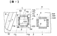
図において、12は凹面部である。この凹面部12は、メタルマスク3の他面側に、特に左側Lの微細ピッチ側の複数個の縦の開口部5及び複数個の横の開口部7全体を囲う領域範囲内にロの字形状に設けられている。この凹面部12の部分のうち特に前記縦の開口部5の周縁部分を肉厚H2の肉薄部11cとなし、この凹面部12の両側の部分のうち特に前記縦の開口部5の両短辺51の近傍部分を肉厚H1の肉厚部11a(前記縦の開口部5の外側の肉厚部)及び肉厚部11b(前記縦の開口部5の内側の肉厚部)となし、この凹面部12の他面側のうち特に前記縦の開口部5の両短辺51のうち少なくとも何れか一方、この例では前記縦の開口部5の内側の短辺51から前記内側の肉厚部11bまでの前記肉薄部11cの他面側をスキージ10が接触する接触面部11dとなし、この凹面部12の他面側のうち前記内側の肉厚部11bの4角(4隅)から前記肉薄部11cの他面側に一体にほぼ垂直に張り出した部分を肉厚H1の張出部11eとなす。この結果、内側の肉厚部11bは、スキ−ジ1の移動方向イに見てIあるいは工字状(開口部5側からの図示の形で云えばH字状)の形状となっている。
【0019】
そして、上述の凹面部12によって肉厚部11a及び11bと肉薄部11cとの境界に形成される段差部120は、スキージ10を変形させてそのスキージ10によるはんだペースト9の縦の開口部5中への圧入力を軽減させるスキージ変形手段を構成する。また、上述の接触面部11dは、スキージ10によりはんだペースト9を縦の開口部5中に長手方向に圧入できる圧入力が得られるスキージ接触手段を構成する。さらに、上述の張出部11eは、スキージ10が図1に示すように移動方向イに対して傾斜した姿勢で移動した場合にそのスキージ10を前記スキージ変形手段(段差部120)による変形状態とほぼ同様に変形させる傾斜用スキージ変形手段を構成する。
【0020】
なお、上述のロ形状の凹面部12は、前記左側Lの微細ピッチ側の複数個の縦の開口部5及び複数個の横の開口部7の深さ、すなわち配線パッド2上に印刷されるはんだペースト9の量を少なく規制するものである。
【0021】
図3は詳細な寸法関係を示したメタルマスク3の一部平面図である。この図において、スキ−ジ10が移動する方向での肉厚部11bの長さX2は、複数個の縦の開口部5のうち両端に位置する開口部5Aの外側の長辺50同士の距離X1より大きく、内側の肉厚部11bを挾んで位置する横の開口部7の内側の短辺71同士の距離X3より小さい。そして、スキ−ジ10が移動する方向イで幅X4をもつ張出部11eは、両端に位置する縦の開口部5Aの外側の長辺50と横の開口部7の内側の短辺71との間に位置されている。また、スキ−ジ10の移動方向イとほぼ直角な方向での張出部11eの長さY2は、内側の肉厚部11bを挾んで位置する縦の開口部5の内側の短辺51同士の距離Y1より小さく、複数個の横の開口部7のうち両端に位置する開口部7の外側の長辺70同士の距離Y3より大きい。そして、スキ−ジ10の移動方向イとほぼ直角な方向での内側の肉厚部11bの長さをY4とすると、本発明者らの実験によれば、Y4≒(0.2〜0.6)×Y1の任意の値を選択することによって良好な印刷結果が得られている。
【0022】
この実施例における本発明のスクリーン印刷機は、上記の如き構成からなり、以下その操作作用について説明する。
まず、スキージ10が矢印イで示す方向に移動されることによって、メタルマスク3の他面側であってスキ−ジ10の前面に置かれたはんだペ−スト8は、スキ−ジ10からメタルマスク3の表面でプリント配線板1に向かう方向の作用力と表面上での回転力を受けて、複数個の縦の開口部5及び複数個の横の開口部7を介して配線パッド2上にはんだペ−スト9として印刷される。
【0023】
このとき、縦の開口部5において、その縦の開口部5の周縁部分の肉薄部11cと、その縦の開口部5の両短辺51の近傍部分の肉厚部11a及び11bとで構成される段差部120により、肉厚部11a及び11bにおいて図4中の実線に示すようにスキージ10の先端が大きく変形し、かつ肉薄部11cにおいて図4中の二点鎖線に示すようにスキージ10が小さく変形する。このために、肉薄部11cにおいてスキージ10がはんだペースト9を縦の開口部5中に圧入する力を軽減させることができる。
この結果、縦の開口部5における圧入力を、その圧入力より小に作用する横の開口部7における圧入力に合わせることができる。すなわち、図5(a)乃至(c)に示す縦の開口部5における印刷状況を、図6(a)乃至(c)に示す横の開口部7における印刷状況に合わせることができるので、微細なピッチに配列されている縦の開口部5及び横の開口部7においてかすれやにじみが生じること無くはんだペースト9を印刷することができる。
ここで、縦の開口部5における印刷状況と横の開口部7における印刷状況とを図5(a)乃至(c)及び図6(a)乃至(c)を参照して説明する。
まず、図5(a)に示すように、スキージ10が縦の開口部5の長辺50を通過した後であっても、上述の変形状態にあるスキージ10の先端が縦の開口部5中に深く入り込まず、その分はんだペースト9を縦の開口部5中に圧入する力が小となる。このために、図5(b)に示すように、はんだペースト9が瞬時に縦の開口部5中全体に圧入されず、スキ−ジ10の移動につれてはんだペースト9の圧入区域が広がる。その状況は、図6(a)及び(b)に示す横の開口部7と同様で、メタルマスク3やスキ−ジ10を押し上げるような反作用力は働かない。従って、図5(c)と図6(c)とで対比して示すように、縦の開口部5と横の開口部7の方向性を問わずに、厚さの不揃いやにじみやかすれがなくはんだ9を印刷することができる。
【0024】
また、この実施例における本発明のスクリーン印刷機は、凹面部12の他面側のうち内側の肉厚部11bの4角(4隅)から肉薄部11cの他面側に一体にほぼ垂直に張り出した部分を肉厚H1の張出部11eとなしたものであるから、図1及び図3中の二点鎖線に示すように、スキージ10が移動方向イに対して傾斜した姿勢で移動した場合に、そのスキージ10が前記張出部11eにより上述の段差部120(スキージ変形手段)による変形状態とほぼ同様の状態に変形する。この結果、スキージ10が移動方向イに対して傾斜した姿勢で移動した場合であっても、そのスキージ10の先端は上述のように確実に変形するので、スキージ10が特に縦の開口部5において変形しないときのかすれやにじみが生じるような虞が無い。
ここで、上述の本発明の張出部11eを具備しないメタルマスク3においてスキージ10が移動方向イに対して傾斜した姿勢で移動した場合にかすれやにじみが生じる原因について説明する。すなわち、図3中の二点鎖線に示すように、スキージ10は外側の肉厚部11aにかかっているが、内側の肉厚部11bにかかっていないので、そのスキージ10の先端は内側の肉厚部11bが無い従来のスクリーン印刷機のメタルマスク3での変形状態と同様の状態に変形するだけとなり、その結果、特に複数個の縦の開口部5のうち端の開口部5においてはスキージ10が充分に変形せず、かすれやにじみが生じる虞があるのである。しかし、本発明のスクリーン印刷機は、上述の張出部11eを具備するので、上述のかすれやにじみが生じる虞が無い。
【0025】
そして、図1及び図3中の二点鎖線に示すように、スキ−ジ10が移動方向イに対して斜めになるのは、意図するとせざるとに係らず、加工精度や取付け時の遊びで僅かに斜めになり、本発明者らの実測では、1〜3度の傾斜は常に観測されており、そのために複数個の縦の開口部5のうち両端の開口部5Aでは、張出部11eがあることによって、必ず、スキ−ジ10の先端は、肉厚部11a及び11bで変形されている。電子部品のリ−ド端子の配置によっては、20度位までの傾きを付けることが考えられるが、この場合でも本発明のスクリーン印刷機は上述のかすれやにじみが生じる虞が無い。
【0026】
さらに、この実施例における本発明のスクリーン印刷機は、縦の開口部5の内側の短辺51から内側の肉厚部11bまでの肉薄部11cの他面側をスキージ10が接触する接触面部11dとなしたものであるから、、スキ−ジ10がその接触面部11dに接触してはんだペースト9を縦の開口部5中に長手方向に圧入できる圧入力が得られる。この結果、図7に示すように、縦の開口部5の外側の短辺51側の肉薄部11cの他面側に、スキ−ジ10が接触せずはんだペ−スト9に圧入力が作用しないデッドスペースDSが形成されたとしても、縦の開口部5の内側の短辺51側の肉薄部11c(接触面部11d)の他面側にスキ−ジ10が接触してはんだペ−スト9を縦の開口部5中に長手方向にデッドスペースDS側(縦の開口部5の外側の短辺51側)まで圧入することができるので、はんだペ−スト9を確実に印刷することができる。
このとき、図8に示すように、縦の開口部5の両短辺51の肉薄部11cの他面側にデッドスペースDSが形成されると、はんだペースト9を縦の開口部5中に圧入する圧入力が得られないので、その縦の開口部5の両短辺部分にはんだペースト9が圧入されない等の問題がある。この実施例における本発明のスクリーン印刷機は、上述の問題を解決することができる。
そして、この実施例における本発明のスクリーン印刷機において、上述の接触面部11dは、上述の例の縦の開口部5の内側の短辺51側の肉薄部11cの他面側に設けたが、縦の開口部5の外側の短辺51側の肉薄部11cの他面側、又は縦の開口部5の両短辺51側の肉薄部11cの他面側に設けても良い。
【0027】
図9乃至図12は肉厚部11a及び11bや張出部11eや凹面部12の形状の変形例を示したメタルマスク3の一部平面図である。
メタルマスク3に対する凹面部12の形成に関しては、図9及び図10に示すように凹面部12(段差部120)の角部を丸くしたり面取りを施して加工作業を容易にすると良い。
なお、図10において、内側の肉厚部11′bは細長い2個のコの字形状をなすものであるが、二点鎖線に示すように1個のIやエの字形状のもの(11b)であっても良い。
また、凹面部12(段差部120)の角部を丸くする加工を発展させた形として、図11に示すように、縦の開口部5及び横の開口部7で囲まれた内側の肉厚部11bを鼓やプ−リを横から見た形としても良い。
さらに、図12に示すように、張出部11′eを、スキ−ジ10の移動方向イに対して斜めに設けても良い。
【0028】
図13及び図14は本発明のスクリーン印刷機の第2の実施例を示す。図中、図1乃至図12及び図16乃至図21と同符号は同一のものを示す。
上述の第1の実施例のものは電子部品としてリード端子14が4方向に延設されたクォーターフラットパッケージ型(QFP型)の電子部品13を搭載するものであるが、この第2の実施例のものは電子部品としてはリード端子140が2方向に延設されたデュアルライン型の電子部品130を縦横に2個搭載するものである。
【0029】
図13においてはデュアルライン型の電子部品130がスキージ10の移動方向イに対してほぼ直角方向に上下(縦)に2個搭載されるものであって、また図14においてはデュアルライン型の電子部品130がスキージ10の移動方向イに左右(横)に2個搭載されるものであって、メタルマスク3に複数個の縦の開口部5と複数個の横の開口部7とがそれぞれ横列状態で2列平行に配列されている。このメタルマスク3の他面側にロの字形状の凹面部12Aを前記2列の複数個の縦の開口部5を囲うように設ける。この結果、縦の開口部5の周縁部分に肉薄部110cが形成され、また縦の開口部5の両短辺51の近傍部分に外側の肉厚部110a及び内側の肉厚部110bがそれぞれ形成され、さらに縦の開口部5の両短辺51のうち少なくとも何れか一方から前記肉厚部110a、110bまでの前記肉薄部110cの他面側に接触面部110dが形成され、さらにその上内側の肉厚部110bの4隅から前記肉薄部110cの他面側に張出部11eが構成される。
【0030】
一方、上述の図13及び図14において、メタルマスク3の他面側に四角形の凹面部40を前記2列の複数個の横の開口部7を囲うようにそれぞれ設ける。この第2の実施例のものは上述の第1の実施例のものと同様の作用効果を達成することができる。
【0031】
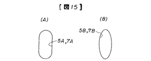
図15(A)及び(B)は縦の開口部及び横の開口部の変形例を示した説明図である。開口部は、上述の長方形形状のもの(5、7)の他に、(A)に示す長円形状のもの(5A、7A)、(B)に示す楕円形状のもの(5B、7B)等、電子部品13、130のリード端子14、140に倣って細長いものであって良い。
【0032】
なお、上述の実施例において、張出部11e、11′e、110eは、内側の肉厚部11b、11′b、110bから肉薄部11c、110cに一体に張り出したものであるが、外側の肉厚部11a、110aから肉薄部11c、110cに一体に張り出しても良いし、又は内外両肉厚部11a、110a及び11b、11′b、110bから肉薄部11c、110cに一体に張り出しても良い。
【0033】
【発明の効果】
以上説明したように本発明のスクリーン印刷機によれば、スキ−ジの移動方向に対するスクリーンマスクに設けられた開口部の向きによる印刷状況(はんだペ−スト印刷量)の差がなく、微細なピッチにおいてもかすれやにじみを生じることなくはんだペ−ストを印刷することができる。
【図面の簡単な説明】
【図1】本発明のスクリーン印刷機の第1の実施例を示し、スクリーン印刷機の印刷部の平面図である。
【図2】メタルマスク(スクリーンマスク)の要部の一部拡大斜視図である。
【図3】メタルマスク(スクリーンマスク)の要部の一部拡大平面図である。
【図4】図3におけるIV−IV線断面図である。
【図5】(a)及び(b)及び(c)は図3におけるV−V線断面図であって、縦の開口部における印刷状況を示した説明図である。
【図6】(a)及び(b)及び(c)は図3におけるVI−VI線断面図であって、横の開口部における印刷状況を示した説明図である。
【図7】図3におけるVII−VII線断面図である。
【図8】縦の開口部の両短辺側の肉薄部の他面側にデッドスペースが形成された場合の問題点を示した説明図である。
【図9】縦の開口部の段差部の角の形状を変えたメタルマスクの変形例を示した一部平面図である。
【図10】縦の開口部の段差部の角の形状や内側の肉厚部の形状を変えたメタルマスクの変形例を示した一部平面図である。
【図11】縦の開口部の内側の肉厚部の形状を変えたメタルマスクの変形例を示した一部平面図である。
【図12】縦の開口部の内側の肉厚部の形状を変えたメタルマスクの変形例を示した一部平面図である。
【図13】本発明のスクリーン印刷機の第2の実施例を示し、スクリーン印刷機の印刷部の平面図である。
【図14】本発明のスクリーン印刷機の第2の実施例の変形例を示し、スクリーン印刷機の印刷部の平面図である。
【図15】(A)は長円形状の開口部を示した説明図、(B)は楕円形状の開口部を示した説明図である。
【図16】従来のスクリーン印刷機の印刷部の拡大平面図である。
【図17】図18におけるA−A線断面図である。
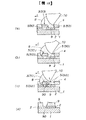
【図18】(a)及び(b)及び(c)及び(d)は図18におけるB−B線断面図であって、縦の開口部における印刷状況を示した説明図である。
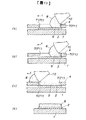
【図19】(a)及び(b)及び(c)及び(d)は図18におけるC−C線断面図であって、横の開口部における印刷状況を示した説明図である。
【図20】図18におけるD−D線断面図である。
【図21】図18におけるE−E線断面図である。
【符号の説明】
1…プリント配線板、2…配線パッド、3…メタルマスク(スクリーンマスク)、4…薄肉部、5…縦の開口部、50…長辺、51…短辺、7…横の開口部、8及び9…はんだペ−スト、10…スキ−ジ、11a及び110a…外側の肉厚部、11b及び11′b及び110b…内側の厚肉部、11c及び110c…肉薄部、11d及び110d…接触部、11e及び11′e及び110e…張出部、12及び12A…凹面部、13…クォーターフラットパッケージ型の電子部品、130…デュアルライン型の電子部品、14及び140…リード端子。[0001]
[Industrial application fields]
In the present invention, a printed wiring board is disposed on one side of the screen mask, and the squeegee is moved on the other side of the screen mask, thereby pressing the solder paste against the other side of the screen mask, The present invention relates to a screen printer that prints the solder paste in the form of the opening on the printed wiring board through the opening provided in the screen mask, and in particular, even in the opening arranged in a fine pitch, blurring and blurring. The present invention relates to a screen printing machine capable of printing a solder paste without causing the above.
[0002]
[Prior art]
Solder paste can be printed on a printed wiring board using a screen printer to mount (adhere) electronic components such as semiconductor devices, resistors, capacitors, etc. on the printed wiring board to realize a required electronic circuit. Has been done.
This type of conventional screen printing machine will be described with reference to FIGS.
16 to 21,
This
[0003]
[0004]
The
[0005]
The
The sizes of the
Further, as shown in FIG. 16, the
[0006]
[0007]
8 is a solder paste placed on the
[0008]
Next, the operation of the screen printing machine having the above-described configuration will be described.
First, by moving the
Next, after separating the
[0009]
[Problems to be solved by the invention]
However, in the above-described conventional screen printing machine, the printing situation in which the
[0010]
FIGS. 18A to 18D and FIG. 20 show the printing situation in the
First, as shown in FIG. 18A and FIG.
Here, the
However, even if the press-in of the
Further, since the
As a result, a push-up reaction acts on the
And as the miniaturization of the opening further progresses and the distance between the adjacent
[0011]
On the other hand, FIGS. 19A to 19D and FIG. 21 show a printing state in the
First, as shown in FIGS. 19A and 21, immediately after the
Here, since the
Further, since the
As a result, almost no force is generated to push up the
Even if the opening is further miniaturized and the distance between the
[0012]
If the pressure input of the
[0013]
Thus, miniaturization of the printing pattern and improvement of printing accuracy are conflicting requirements.
[0014]
An object of the present invention is to provide a screen printer capable of printing a solder paste without causing blurring or blurring even in openings arranged at a fine pitch.
[0015]
[Means for Solving the Problems]
In order to achieve the above object, the present invention provides A concave portion is provided on the other surface side of the screen mask, and a thin portion and a thick portion are formed by the concave portion, and the longitudinal direction of the opening and the moving direction of the squeegee are substantially perpendicular to each other. The openings are arranged in the thin portions in a state of being aligned in rows so that the longitudinal directions of the openings are parallel, and the thin portions and the thin portions are opposed to both short sides of the openings. There is a step portion formed by the thick portion, and the step portion facing both short sides of the opening is deformed by deforming the squeegee so that the solder paste by the squeegee is disposed in the longitudinal direction of the opening and the squeegee. The squeegee deforming means for reducing press-fitting for press-fitting into the opening that is substantially perpendicular to the direction of movement of the die, and openings located at both ends of the openings aligned in the row In the position outside the section The squeegee is moved in a posture in which the squeegee is inclined with respect to the moving direction, with the protruding portions protruding from the squeegee deforming means to the thin part in a direction substantially perpendicular to the moving direction of the squeegee, each having the same thickness as the squeegee changing means In this case, the squeegee deforms the squeegee deforming means for deforming the squeegee almost in the same manner as the deformed state by the squeegee deforming means. It is characterized by that.
[0016]
[Action]
In the present invention, a stepped portion is formed on the other surface side of the screen mask by the thin portion at the peripheral portion of the vertical opening and the thick portion in the vicinity of both short sides of the vertical opening. By this step portion, the squeegee is greatly deformed at the thick portion and small at the thin portion. For this reason, it is possible to reduce the force with which the squeegee presses the solder paste into the vertical opening in the thin portion. As a result, the pressure input at the vertical opening is changed to the pressure input at the horizontal opening (opening in which the longitudinal direction of the opening and the moving direction of the squeegee are substantially parallel) acting to a smaller extent than the pressure input. Can be matched. That is, since the printing situation in the vertical opening can be matched to the printing situation in the horizontal opening, the solder is not generated in the vertical opening and the horizontal opening arranged in a fine pitch without blurring or blurring. The paste can be printed.
[0017]
Further, according to the present invention, when the squeegee is moved in a posture inclined with respect to the moving direction by the overhanging portion integrally projecting from the thick portion to the thin portion on the other surface side of the thin portion, the squeegee has the above-described step difference. It is deformed to a state substantially similar to the deformed state by the part. As a result, even when the squeegee is moved in a posture inclined with respect to the moving direction, the squeegee is surely deformed, and there is a risk that blurring or blurring may occur when the squeegee is not deformed particularly in the vertical opening. There is no.
[0018]
【Example】
Hereinafter, two examples of the screen printing machine according to the present invention will be described in detail with reference to FIGS. 1 to 7 and FIGS. 9 to 15.
1 to 7 show a first embodiment of a screen printing machine according to the present invention. In the figure, the same reference numerals as those in FIGS. 16 to 21 denote the same components.
In the figure, 12 is a concave surface portion. This
[0019]
The
[0020]
The above-mentioned concave
[0021]
FIG. 3 is a partial plan view of the
[0022]
The screen printing machine of the present invention in this embodiment is configured as described above, and its operation will be described below.
First, when the
[0023]
At this time, the
As a result, the pressure input in the
Here, the printing situation in the
First, as shown in FIG. 5A, even after the
[0024]
Further, the screen printing machine of the present invention in this embodiment is substantially perpendicular to the other surface side of the
Here, a description will be given of the cause of blurring and blurring when the
[0025]
As shown by the two-dot chain line in FIGS. 1 and 3, the
[0026]
Furthermore, the screen printing machine of the present invention in this embodiment is configured such that the
At this time, as shown in FIG. 8, when a dead space DS is formed on the other surface side of the
And In this example In the screen printing machine of the present invention, the
[0027]
9 to 12 are partial plan views of the
Regarding the formation of the
In FIG. 10, the inner thick portion 11′b has two elongated U-shapes. However, as shown by a two-dot chain line, one thick I-shaped or 11-shaped shape (11b ).
Also, the concave surface portion 12 (stepped
Further, as shown in FIG. 12, the overhanging portion 11 ′ e may be provided obliquely with respect to the moving direction “a” of the
[0028]
13 and 14 show a second embodiment of the screen printing machine of the present invention. In the figure, the same reference numerals as those in FIGS. 1 to 12 and FIGS. 16 to 21 denote the same components.
In the first embodiment described above, a quarter flat package type (QFP type)
[0029]
In FIG. 13, two dual-line
[0030]
On the other hand, the above figure 13 And figure 14 4, a rectangular
[0031]
FIGS. 15A and 15B are explanatory views showing modifications of the vertical opening and the horizontal opening. In addition to the rectangular shape (5, 7) described above, the opening has an elliptical shape (5A, 7A) shown in (A), an elliptical shape (5B, 7B) shown in (B), etc. The
[0032]
In the above-described embodiment, the
[0033]
【The invention's effect】
As described above, according to the screen printing machine of the present invention, there is no difference in the printing situation (solder paste printing amount) depending on the direction of the opening provided in the screen mask with respect to the moving direction of the squeegee, and it is fine. The solder paste can be printed without causing blurring or blurring even on the pitch.
[Brief description of the drawings]
FIG. 1 is a plan view of a printing unit of a screen printing machine according to a first embodiment of the screen printing machine of the present invention.
FIG. 2 is a partially enlarged perspective view of a main part of a metal mask (screen mask).
FIG. 3 is a partially enlarged plan view of a main part of a metal mask (screen mask).
4 is a cross-sectional view taken along line IV-IV in FIG.
FIGS. 5A, 5B, and 5C are cross-sectional views taken along line VV in FIG. 3 and are explanatory diagrams illustrating a printing state in a vertical opening.
6A, 6B, and 6C are cross-sectional views taken along the line VI-VI in FIG. 3 and are explanatory views showing a printing state in a lateral opening.
7 is a cross-sectional view taken along line VII-VII in FIG.
FIG. 8 is an explanatory view showing a problem when a dead space is formed on the other surface side of the thin portion on both short sides of the vertical opening.
FIG. 9 is a partial plan view showing a modification of the metal mask in which the corner shape of the step portion of the vertical opening is changed.
FIG. 10 is a partial plan view showing a modification of the metal mask in which the shape of the corner of the step portion of the vertical opening and the shape of the inner thick portion are changed.
FIG. 11 is a partial plan view showing a modified example of the metal mask in which the shape of the thick portion inside the vertical opening is changed.
FIG. 12 is a partial plan view showing a modification of the metal mask in which the shape of the thick part inside the vertical opening is changed.
FIG. 13 is a plan view of a printing unit of a screen printing machine according to a second embodiment of the screen printing machine of the present invention.
FIG. 14 is a plan view of a printing unit of a screen printing machine, showing a modification of the second embodiment of the screen printing machine of the present invention.
15A is an explanatory view showing an oval opening, and FIG. 15B is an explanatory view showing an oval opening.
FIG. 16 is an enlarged plan view of a printing unit of a conventional screen printing machine.
17 is a cross-sectional view taken along line AA in FIG.
18 (a), (b), (c) and (d) are cross-sectional views taken along the line BB in FIG.
19 (a), (b), (c), and (d) are cross-sectional views taken along the line CC in FIG.
20 is a sectional view taken along line DD in FIG.
FIG. 21 is a cross-sectional view taken along line EE in FIG.
[Explanation of symbols]
DESCRIPTION OF
Claims (3)
前記スクリーンマスクの他面側には凹面部が設けられて当該凹面部によって肉薄部と肉厚部とが形成され、開口部の長手方向と前記スキ−ジの移動方向とがほぼ直角である複数のその開口部は各開口部の長手方向が平行となるように横列に整列させた状態で前記肉薄部に配列されており、それらの開口部の両短辺と対向するように前記肉薄部と前記肉厚部とにより形成された段差部があり、それらの開口部の両短辺と対向する段差部を、前記スキージを変形させてそのスキージによる前記はんだペーストを開口部の長手方向と前記スキ−ジの移動方向とがほぼ直角であるその開口部の中へ圧入するための圧入力を軽減させるスキージ変形手段となし、かつ、前記横列に整列されたそれらの開口部のうち両端に位置する開口部より外側の位置においてそれぞれ前記スキージ変形手段と同厚で前記スキージの移動方向とほぼ直角な方向に前記スキージ変形手段から前記肉薄部に張り出した張出部を、前記スキージが移動方向に対して傾斜した姿勢で移動した場合にそのスキージを前記スキージ変形手段による変形状態とほぼ同様に変形させる傾斜用スキージ変形手段となすことを特徴とするスクリーン印刷機。A printed wiring board is disposed on one side of the screen mask, and the squeegee is moved on the other side of the screen mask so that the solder paste is pressed against the other side of the screen mask and the solder paste is applied. In a screen printer that prints in the form of the opening on the printed wiring board through the opening provided in the screen mask,
Wherein the other surface side of the screen mask concave portion is formed and a thin portion and a thick portion by the concave portion is formed, the a longitudinal opening liked - plurality of the moving direction of di is approximately perpendicular its opening of being arranged on the thin portion in a state where the longitudinal direction of each opening is aligned in rows in parallel, and the thin portion so as to face the two short sides of those openings There is a step portion formed by the thick portion, and the step portion facing both short sides of the opening portion is deformed by deforming the squeegee so that the solder paste by the squeegee is applied to the longitudinal direction of the opening portion and the squeegee. -A squeegee deforming means for reducing press-fitting for press-fitting into the opening which is substantially perpendicular to the direction of movement of the die, and located at both ends of the openings aligned in the row In the position outside the opening The squeegee is moved in a posture in which the squeegee is inclined with respect to the moving direction in a direction that is the same thickness as the squeegee deforming means and is substantially perpendicular to the moving direction of the squeegee. In this case, the screen squeegee is a tilting squeegee deforming means for deforming the squeegee in substantially the same manner as the deformed state by the squeegee deforming means .
Priority Applications (1)
| Application Number | Priority Date | Filing Date | Title |
|---|---|---|---|
| JP06111194A JP3632092B2 (en) | 1994-03-30 | 1994-03-30 | Screen printing machine |
Applications Claiming Priority (1)
| Application Number | Priority Date | Filing Date | Title |
|---|---|---|---|
| JP06111194A JP3632092B2 (en) | 1994-03-30 | 1994-03-30 | Screen printing machine |
Publications (2)
| Publication Number | Publication Date |
|---|---|
| JPH07266537A JPH07266537A (en) | 1995-10-17 |
| JP3632092B2 true JP3632092B2 (en) | 2005-03-23 |
Family
ID=13161652
Family Applications (1)
| Application Number | Title | Priority Date | Filing Date |
|---|---|---|---|
| JP06111194A Expired - Fee Related JP3632092B2 (en) | 1994-03-30 | 1994-03-30 | Screen printing machine |
Country Status (1)
| Country | Link |
|---|---|
| JP (1) | JP3632092B2 (en) |
-
1994
- 1994-03-30 JP JP06111194A patent/JP3632092B2/en not_active Expired - Fee Related
Also Published As
| Publication number | Publication date |
|---|---|
| JPH07266537A (en) | 1995-10-17 |
Similar Documents
| Publication | Publication Date | Title |
|---|---|---|
| JP3553405B2 (en) | Chip type electronic components | |
| JP3632092B2 (en) | Screen printing machine | |
| JP3643914B2 (en) | Screen printing machine | |
| JP3056498U (en) | Unit with shield | |
| JP2675473B2 (en) | Flat package IC Solder dip type printed wiring board | |
| JP2838023B2 (en) | Screen printing machine | |
| US6898847B2 (en) | Method for producing an electrical connection between a plug element and a printed circuit board | |
| JPH03151686A (en) | Printed wiring board | |
| US20070051255A1 (en) | Apparatus and method for increasing deposition of printing material | |
| JP2725646B2 (en) | Semiconductor component and its mounting method | |
| JPH0621220Y2 (en) | Leadless parts equipment | |
| JPH05121868A (en) | Soldering package method of electronic part on printed substrate | |
| JP2636332B2 (en) | Printed board | |
| JP4560880B2 (en) | Screen mask and screen printing method | |
| JPH0611531Y2 (en) | Circuit board device | |
| JP2606304B2 (en) | Cream solder printing method | |
| JP2591505B2 (en) | Printed wiring board | |
| JP4844260B2 (en) | Electronic component and manufacturing method thereof | |
| JP2528436B2 (en) | Manufacturing method of circuit board device | |
| JPH0718476U (en) | Printed board | |
| JPH04243187A (en) | Printed circuit board | |
| JP2002232109A (en) | Printed board | |
| JPH0384988A (en) | Printed board | |
| JP2021072357A (en) | Metal terminal and connection structure | |
| JP2008192869A (en) | Metal mask |
Legal Events
| Date | Code | Title | Description |
|---|---|---|---|
| A01 | Written decision to grant a patent or to grant a registration (utility model) |
Free format text: JAPANESE INTERMEDIATE CODE: A01 Effective date: 20040921 |
|
| A61 | First payment of annual fees (during grant procedure) |
Free format text: JAPANESE INTERMEDIATE CODE: A61 Effective date: 20041005 |
|
| A61 | First payment of annual fees (during grant procedure) |
Free format text: JAPANESE INTERMEDIATE CODE: A61 Effective date: 20041203 |
|
| R150 | Certificate of patent or registration of utility model |
Free format text: JAPANESE INTERMEDIATE CODE: R150 |
|
| S111 | Request for change of ownership or part of ownership |
Free format text: JAPANESE INTERMEDIATE CODE: R313111 |
|
| R350 | Written notification of registration of transfer |
Free format text: JAPANESE INTERMEDIATE CODE: R350 |
|
| FPAY | Renewal fee payment (event date is renewal date of database) |
Free format text: PAYMENT UNTIL: 20080107 Year of fee payment: 3 |
|
| FPAY | Renewal fee payment (event date is renewal date of database) |
Free format text: PAYMENT UNTIL: 20090107 Year of fee payment: 4 |
|
| FPAY | Renewal fee payment (event date is renewal date of database) |
Free format text: PAYMENT UNTIL: 20090107 Year of fee payment: 4 |
|
| FPAY | Renewal fee payment (event date is renewal date of database) |
Free format text: PAYMENT UNTIL: 20100107 Year of fee payment: 5 |
|
| FPAY | Renewal fee payment (event date is renewal date of database) |
Free format text: PAYMENT UNTIL: 20110107 Year of fee payment: 6 |
|
| LAPS | Cancellation because of no payment of annual fees |