JP3634431B2 - 制動弁 - Google Patents
制動弁 Download PDFInfo
- Publication number
- JP3634431B2 JP3634431B2 JP03697695A JP3697695A JP3634431B2 JP 3634431 B2 JP3634431 B2 JP 3634431B2 JP 03697695 A JP03697695 A JP 03697695A JP 3697695 A JP3697695 A JP 3697695A JP 3634431 B2 JP3634431 B2 JP 3634431B2
- Authority
- JP
- Japan
- Prior art keywords
- piston
- prefill
- brake
- stepped
- fluid
- Prior art date
- Legal status (The legal status is an assumption and is not a legal conclusion. Google has not performed a legal analysis and makes no representation as to the accuracy of the status listed.)
- Expired - Fee Related
Links
- 230000007246 mechanism Effects 0.000 claims description 17
- 239000012530 fluid Substances 0.000 claims description 16
- 238000009530 blood pressure measurement Methods 0.000 description 2
- 238000012986 modification Methods 0.000 description 2
- 230000004048 modification Effects 0.000 description 2
- 230000007935 neutral effect Effects 0.000 description 1
Images

Classifications
-
- B—PERFORMING OPERATIONS; TRANSPORTING
- B60—VEHICLES IN GENERAL
- B60T—VEHICLE BRAKE CONTROL SYSTEMS OR PARTS THEREOF; BRAKE CONTROL SYSTEMS OR PARTS THEREOF, IN GENERAL; ARRANGEMENT OF BRAKING ELEMENTS ON VEHICLES IN GENERAL; PORTABLE DEVICES FOR PREVENTING UNWANTED MOVEMENT OF VEHICLES; VEHICLE MODIFICATIONS TO FACILITATE COOLING OF BRAKES
- B60T11/00—Transmitting braking action from initiating means to ultimate brake actuator without power assistance or drive or where such assistance or drive is irrelevant
- B60T11/10—Transmitting braking action from initiating means to ultimate brake actuator without power assistance or drive or where such assistance or drive is irrelevant transmitting by fluid means, e.g. hydraulic
- B60T11/16—Master control, e.g. master cylinders
- B60T11/224—Master control, e.g. master cylinders with pressure-varying means, e.g. with two stage operation provided by use of different piston diameters including continuous variation from one diameter to another
-
- B—PERFORMING OPERATIONS; TRANSPORTING
- B60—VEHICLES IN GENERAL
- B60T—VEHICLE BRAKE CONTROL SYSTEMS OR PARTS THEREOF; BRAKE CONTROL SYSTEMS OR PARTS THEREOF, IN GENERAL; ARRANGEMENT OF BRAKING ELEMENTS ON VEHICLES IN GENERAL; PORTABLE DEVICES FOR PREVENTING UNWANTED MOVEMENT OF VEHICLES; VEHICLE MODIFICATIONS TO FACILITATE COOLING OF BRAKES
- B60T13/00—Transmitting braking action from initiating means to ultimate brake actuator with power assistance or drive; Brake systems incorporating such transmitting means, e.g. air-pressure brake systems
- B60T13/10—Transmitting braking action from initiating means to ultimate brake actuator with power assistance or drive; Brake systems incorporating such transmitting means, e.g. air-pressure brake systems with fluid assistance, drive, or release
- B60T13/12—Transmitting braking action from initiating means to ultimate brake actuator with power assistance or drive; Brake systems incorporating such transmitting means, e.g. air-pressure brake systems with fluid assistance, drive, or release the fluid being liquid
- B60T13/16—Transmitting braking action from initiating means to ultimate brake actuator with power assistance or drive; Brake systems incorporating such transmitting means, e.g. air-pressure brake systems with fluid assistance, drive, or release the fluid being liquid using pumps directly, i.e. without interposition of accumulators or reservoirs
- B60T13/161—Systems with master cylinder
- B60T13/165—Master cylinder integrated or hydraulically coupled with booster
Landscapes
- Engineering & Computer Science (AREA)
- Transportation (AREA)
- Mechanical Engineering (AREA)
- Valves And Accessory Devices For Braking Systems (AREA)
- Transmission Of Braking Force In Braking Systems (AREA)
- Braking Systems And Boosters (AREA)
Description
【産業上の利用分野】
本発明は、一対の二段式制動装置制御弁を含む制動装置制御弁アッセンブリに関する。
【0002】
【従来の技術】
周知の二段式制動装置制御弁は、1988年4月19日に賦与された、本願の譲受人に譲渡された米国特許第4,738,109号に記載されている。このような制動弁は、制動弁ポンプ圧力入口のところでポンプ圧力を利用できない場合でも手動で制動できるようにする。これは、プレフィルピストン及び高圧ピストンを含む二段弁装置によって達成される。プレフィルピストンは、後側のアクスルの制動装置構成要素を係合させるのに必要な大量のオイル及びこれと関連した低い油圧を提供する。ひとたびこの容積が満たされると、制動弁は、制動に必要な高圧を発生させるため、比較的大径のプレフィルピストンから比較的小径の高圧ピストンに移行する。
【0003】
制動弁ポンプ入口のところでポンプ圧力が利用できる状態では、制動弁(プレフィルピストン/高圧ピストン)を掛けるには中立位置から圧力計測位置まで僅かに移動させるだけでよい。しかしながら、この移動中、流体は実質的に捕捉されており、プレフィルチャンバ内で圧力が発生し、その結果、ペダルを重く感じる。ペダルを重く感じるため及び制動を加えるのに比較的大きなペダル力をこれと関連して必要とされるため、プレフィルチャンバの最終的な圧力低下により制動圧力の制御が失われる。ペダルのこの重い感触は、寒冷気候状態で更に強く感じる。これは、圧力低下時間が増加するためである。
【0004】
【発明が解決しようとする課題】
本発明の目的は、ペダルを重く感じさせることのない制動弁を提供することである。
【0005】
【課題を解決するための手段】
この目的及び他の目的は、左右の二段式制動弁が流体圧力を左右の制動機構に伝える本発明によって達成される。各制動弁は、ポンプから加圧制動流体を受入れるための入口、リザーバポート、段付きボア、及び大径のプレフィルピストン及び小径の高圧ピストンからなる段付きピストン部材とを有する。段付きピストンは、流体を制動機構に移送するため、休止位置から遠ざかるように移動できる。段付きボア及び段付きピストンは、高容積プレフィルチャンバ及び高圧チャンバを形成する。高圧ピストンは、制動機構と連通した溝を有し、この溝は、高圧ピストンを特定の距離だけ移動させたときに入口と連通して流体を高圧チャンバから制動機構まで移送する。プレフィルピストンは、段付きボア内で摺動自在のシールリングの両側にシールランド及び第2ランドを有する。シールランドは、プレフィルピストンを移動して流体をプレフィルチャンバから制動機構まで移送するとき、シールリングと密封係合する。シールランドは、段付きピストンがその休止位置にあるとき、溝と入口との間の距離以上の所定の距離だけシールリングから間隔を隔てられている。
【0006】
【実施例】
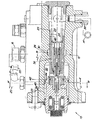
図1を参照すると、この図には従来の双二段式制動弁10の側面図が示してあり、この弁のハウジング11には、流体圧力を左側制動機構(図示せず)及び右側制動機構14に連通するための左側二段式制動弁(図示せず)及び右側二段式制動弁12が収容されている。各制動弁は、ポンプ18から加圧制動流体を受入れるための入口16、この入口16と連通した入口溝19、リザーバ22と連通するためのリザーバポート20、大径区分23及び小径区分25を持つ段付きボア24を有する。段付きピストン部材26は、大径のプレフィルピストン28及び小径の高圧ピストン30を含む。段付きボア24及び段付きピストン部材26は、大容積プレフィルチャンバ32及び高圧チャンバ34を形成する。高圧ピストン30には、出口38を介して制動機構14と連通した溝36が設けられている。この溝36は、高圧ピストン30を特定の距離Dだけ移動して流体を高圧チャンバ34から制動機構14に移送したとき、入口16と連通する。プレフィルピストン28は、ボア23内で摺動自在のシールリング44の両側にシールランド40及び第2ランド42を有する。シールランド40は、プレフィルピストン28を距離dに亘って移動したとき、シールリング44と密封係合し、この時、プレフィルピストン28を図1で見て右方に更に移動させると、流体がプレフィルチャンバ32から制動機構14に移送される。ばね46は、ピストン部材26を休止位置に向かって左方に押圧するように賦勢している。
【0007】
次に、図2を参照すると、本発明によれば、シールランド40’ はシールリング44から距離d’ だけ間隔を隔てられている。この距離は、ピストン部材26がその休止位置にある場合の溝19の縁部と溝36の縁部との間の距離Dよりも大きい。かくして、プレフィルピストン28が距離dに亘って移動したとき、ランド40はシールリング44と密封係合し、このとき、プレフィルピストン28を図1で見て右方に更に移動させると、流体がプレフィルチャンバ32から制動機構14に移送される。このため、ランド40’ は、休止位置から溝19及び36が互いに重なり始める圧力計測位置までのピストン部材26の移動中、リング44と係合することがない。その結果、ピストンのこの初期移動中、流体がプレフィルチャンバ32に捕捉されることがなく、かくして、ペダルを重く感じることがないようにする。
【0008】
本発明を特定の実施例と関連して説明したが、以上の説明から多くの変形及び変更が当業者には明らかであるということは理解されよう。従って、本発明は、添付の特許請求の範囲の精神及び範疇のこのような変形及び変更を含む。
【図面の簡単な説明】
【図1】従来技術の二段式制動弁の断面図である。
【図2】本発明による二段式制動弁の断面図である。
【符号の説明】
12 右側の二段式制動弁
14 右側制動機構
16 入口
18 ポンプ
19 入口溝
20 リザーバポート
22 リザーバ
24 段付きボア
26 段付きピストン部材
28 プレフィルピストン
30 高圧ピストン
32 大容積プレフィルチャンバ
34 高圧チャンバ
36 連通溝
40、40’ シールランド
42 第2ランド
44 シールリング
Claims (1)
- 流体圧力を制動機構に連通するための二段式制動弁であって、該制動弁は、ポンプから加圧制動流体を受入れるための入口、リザーバポート、段付きボア、及び大径のプレフィルピストン及び小径の高圧ピストンからなる段付きピストン部材とを有し、該段付きピストンは、流体を前記制動機構に移送するため、休止位置から遠ざかるように移動でき、前記段付きボア及び前記段付きピストンは、高容積プレフィルチャンバ及び高圧チャンバを形成し、前記高圧ピストンは、前記制動機構と連通した溝を有し、該溝は、前記高圧ピストンを特定の距離だけ移動させたときに前記入口と連通して流体を前記高圧チャンバから前記制動機構まで移送し、前記プレフィルピストンは、前記段付きボア内で摺動自在のシールリングの両側にシールランド及び第2ランドを有し、前記シールランドは、前記プレフィルピストンを移動して流体を前記プレフィルチャンバから前記制動機構まで移送するとき、前記シールリングと密封係合できる、二段式制動弁において、
前記シールランドは、前記段付きピストンがその休止位置にあるとき、前記溝と前記入口との間の距離以上の所定の距離だけシールリングから間隔を隔てられている、ことを特徴とする二段式制動弁。
Applications Claiming Priority (2)
| Application Number | Priority Date | Filing Date | Title |
|---|---|---|---|
| US201548 | 1994-02-25 | ||
| US08/201,548 US5400595A (en) | 1994-02-25 | 1994-02-25 | Brake valve with prefill chamber unloading |
Publications (2)
| Publication Number | Publication Date |
|---|---|
| JPH07267074A JPH07267074A (ja) | 1995-10-17 |
| JP3634431B2 true JP3634431B2 (ja) | 2005-03-30 |
Family
ID=22746283
Family Applications (1)
| Application Number | Title | Priority Date | Filing Date |
|---|---|---|---|
| JP03697695A Expired - Fee Related JP3634431B2 (ja) | 1994-02-25 | 1995-02-24 | 制動弁 |
Country Status (7)
| Country | Link |
|---|---|
| US (1) | US5400595A (ja) |
| EP (1) | EP0669241B1 (ja) |
| JP (1) | JP3634431B2 (ja) |
| AU (1) | AU680082B2 (ja) |
| BR (1) | BR9500689A (ja) |
| DE (1) | DE59505740D1 (ja) |
| ES (1) | ES2130458T3 (ja) |
Families Citing this family (1)
| Publication number | Priority date | Publication date | Assignee | Title |
|---|---|---|---|---|
| US5778672A (en) | 1996-10-17 | 1998-07-14 | Deere & Company | Brake valve |
Family Cites Families (7)
| Publication number | Priority date | Publication date | Assignee | Title |
|---|---|---|---|---|
| US3764183A (en) * | 1971-12-27 | 1973-10-09 | Deere & Co | Hydraulic brake actuator |
| IT1063732B (it) * | 1976-01-21 | 1985-02-11 | Benditalia S D A | Dispositivo di tenuta tra una scato la munita di un foro ed un pistone spostabile entro tale foro |
| GB1551455A (en) * | 1976-03-16 | 1979-08-30 | Wagner Elecric Corp | Brake master cylinder with auxiliary piston |
| US4671168A (en) * | 1985-02-27 | 1987-06-09 | Bendix France | Single actuator tandem brake pressure control valve |
| US4738109A (en) * | 1986-11-04 | 1988-04-19 | Deere & Company | Two stage brake control valve |
| GB8700651D0 (en) * | 1987-01-13 | 1987-02-18 | Lucas Ind Plc | Tandem master cylinder |
| DE3911911A1 (de) * | 1989-04-12 | 1990-10-18 | Bosch Gmbh Robert | Zylinder-kolben-einheit mit zentralventil, insbesondere fuer fahrzeugbremsanlagen |
-
1994
- 1994-02-25 US US08/201,548 patent/US5400595A/en not_active Expired - Lifetime
-
1995
- 1995-02-15 DE DE59505740T patent/DE59505740D1/de not_active Expired - Lifetime
- 1995-02-15 EP EP95102059A patent/EP0669241B1/de not_active Expired - Lifetime
- 1995-02-15 ES ES95102059T patent/ES2130458T3/es not_active Expired - Lifetime
- 1995-02-17 AU AU12323/95A patent/AU680082B2/en not_active Ceased
- 1995-02-17 BR BR9500689A patent/BR9500689A/pt not_active IP Right Cessation
- 1995-02-24 JP JP03697695A patent/JP3634431B2/ja not_active Expired - Fee Related
Also Published As
| Publication number | Publication date |
|---|---|
| AU1232395A (en) | 1995-09-07 |
| DE59505740D1 (de) | 1999-06-02 |
| EP0669241B1 (de) | 1999-04-28 |
| JPH07267074A (ja) | 1995-10-17 |
| EP0669241A3 (de) | 1996-12-18 |
| BR9500689A (pt) | 1995-10-24 |
| AU680082B2 (en) | 1997-07-17 |
| EP0669241A2 (de) | 1995-08-30 |
| ES2130458T3 (es) | 1999-07-01 |
| US5400595A (en) | 1995-03-28 |
Similar Documents
| Publication | Publication Date | Title |
|---|---|---|
| US4176886A (en) | Brake apparatus for motorcycle | |
| US4229050A (en) | Brake force regulator for a motorcycle hydraulic brake system | |
| JP3582155B2 (ja) | 車両用ブレーキ制御装置 | |
| US4490977A (en) | Hydraulic brake booster | |
| US4653814A (en) | Power brake booster for a hydraulic vehicle brake system | |
| US4708405A (en) | Brake pressure generator for a hydraulic brake system for use with motor vehicles | |
| US6267456B1 (en) | Brake master cylinder and pedal feel emulator | |
| JP3579968B2 (ja) | 車両用ブレーキ制御装置 | |
| US4159853A (en) | Pressure control unit for a vehicular hydraulic braking system | |
| JPH0323387B2 (ja) | ||
| JP3634431B2 (ja) | 制動弁 | |
| JPS59137244A (ja) | 圧力制御装置 | |
| US4671168A (en) | Single actuator tandem brake pressure control valve | |
| US3877227A (en) | Supported line pressure power brake assembly | |
| US3939658A (en) | Power brake booster | |
| JP3577790B2 (ja) | 車両用ブレーキ制御装置 | |
| JP3640695B2 (ja) | 二段ブレーキ弁 | |
| JPS5940659B2 (ja) | 車輌ブレ−キ系の水圧サ−ボブレ−キ装置 | |
| JP2734619B2 (ja) | 液圧ブレーキ装置 | |
| US4444436A (en) | Hydraulic pressure control valve | |
| US4466458A (en) | Control valve | |
| CA2144246C (en) | Brake valve with prefill chamber unloading | |
| JP3273386B2 (ja) | 車両用ブレーキ圧制御装置 | |
| JP3724837B2 (ja) | 車両用ブレーキ装置 | |
| JP2636474B2 (ja) | 液圧制動装置 |
Legal Events
| Date | Code | Title | Description |
|---|---|---|---|
| A601 | Written request for extension of time |
Free format text: JAPANESE INTERMEDIATE CODE: A601 Effective date: 20040121 |
|
| A602 | Written permission of extension of time |
Free format text: JAPANESE INTERMEDIATE CODE: A602 Effective date: 20040126 |
|
| TRDD | Decision of grant or rejection written | ||
| A01 | Written decision to grant a patent or to grant a registration (utility model) |
Free format text: JAPANESE INTERMEDIATE CODE: A01 Effective date: 20041126 |
|
| A61 | First payment of annual fees (during grant procedure) |
Free format text: JAPANESE INTERMEDIATE CODE: A61 Effective date: 20041224 |
|
| R150 | Certificate of patent or registration of utility model |
Free format text: JAPANESE INTERMEDIATE CODE: R150 |
|
| FPAY | Renewal fee payment (event date is renewal date of database) |
Free format text: PAYMENT UNTIL: 20090107 Year of fee payment: 4 |
|
| FPAY | Renewal fee payment (event date is renewal date of database) |
Free format text: PAYMENT UNTIL: 20100107 Year of fee payment: 5 |
|
| FPAY | Renewal fee payment (event date is renewal date of database) |
Free format text: PAYMENT UNTIL: 20110107 Year of fee payment: 6 |
|
| FPAY | Renewal fee payment (event date is renewal date of database) |
Free format text: PAYMENT UNTIL: 20120107 Year of fee payment: 7 |
|
| FPAY | Renewal fee payment (event date is renewal date of database) |
Free format text: PAYMENT UNTIL: 20130107 Year of fee payment: 8 |
|
| FPAY | Renewal fee payment (event date is renewal date of database) |
Free format text: PAYMENT UNTIL: 20130107 Year of fee payment: 8 |
|
| R250 | Receipt of annual fees |
Free format text: JAPANESE INTERMEDIATE CODE: R250 |
|
| LAPS | Cancellation because of no payment of annual fees |