JP3661902B2 - 光位置検出装置 - Google Patents
光位置検出装置 Download PDFInfo
- Publication number
- JP3661902B2 JP3661902B2 JP35118896A JP35118896A JP3661902B2 JP 3661902 B2 JP3661902 B2 JP 3661902B2 JP 35118896 A JP35118896 A JP 35118896A JP 35118896 A JP35118896 A JP 35118896A JP 3661902 B2 JP3661902 B2 JP 3661902B2
- Authority
- JP
- Japan
- Prior art keywords
- light receiving
- receiving area
- optical fiber
- optical
- optical position
- Prior art date
- Legal status (The legal status is an assumption and is not a legal conclusion. Google has not performed a legal analysis and makes no representation as to the accuracy of the status listed.)
- Expired - Fee Related
Links
- 230000003287 optical effect Effects 0.000 title claims description 18
- 239000013307 optical fiber Substances 0.000 claims description 28
- 238000001514 detection method Methods 0.000 claims description 16
- 230000035945 sensitivity Effects 0.000 description 5
- XEEYBQQBJWHFJM-UHFFFAOYSA-N Iron Chemical compound [Fe] XEEYBQQBJWHFJM-UHFFFAOYSA-N 0.000 description 4
- 238000010586 diagram Methods 0.000 description 4
- 229910052742 iron Inorganic materials 0.000 description 2
- 239000000571 coke Substances 0.000 description 1
- 230000000694 effects Effects 0.000 description 1
- 239000000446 fuel Substances 0.000 description 1
- 230000008018 melting Effects 0.000 description 1
- 238000002844 melting Methods 0.000 description 1
Images

Landscapes
- Length Measuring Devices By Optical Means (AREA)
- Measurement Of Optical Distance (AREA)
Description
【発明の属する技術分野】
本発明は、受光エリアを直線状に配置し各受光エリアへ位置を検出する光位置検出装置に関する。
【0002】
【従来の技術】
鉄鉱石を溶解する高炉では、通常、炉の上部からコークスと鉄鉱石を交互に装入し、その後攪拌機により炉頂面のプロファイルが断面V字形となるように設定する。炉頂プロファイルを所望のV字形にすることは高炉の燃費を節約する上で非常に重要な意味をもっており、従って炉頂プロファイルを正確に測定する手段が要求される。
【0003】
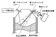
この要求を満たすために、図2に示すような高炉プロファイル検出装置が用いられる。本装置はレーザを発生するレーザ発生器と、この発生したレーザを反射して高炉炉頂面を走査する第1スキャニングミラーと、炉頂面を走査するレーザの反射光を捕捉し反射する第2スキャニングミラーと、この第2スキャニングミラーの反射光を受光して炉頂面のプロファイルを検出する光位置検出機から構成されている。
【0004】
光位置検出機には光位置を受光して電気信号に変換する光位置検出装置が設けられている。図3はこの光位置検出装置を示す。光位置検出装置は、炉頂面から反射してくる微弱な光を受光する受光エリア4を直線状に配列した受光エリア群1と、この各受光エリア4に接続する光ファイバ2と、光ファイバ2からの光を電気信号に変換する光電変換器3より構成されている。各受光エリア4は同一の面積を有し、同数の光ファイバ素子の端面が均一に配置されており、この各受光エリア4の光ファイバ素子を束ねて光ファイバ2が構成されている。
【0005】
【発明が解決しようとする課題】
第1スキャニングミラーが炉頂面に沿ってレーザを走査してゆき、この反射光を第2スキャニングミラーが追跡し反射して光を受光エリア群1に当ててゆく。定常状態になれば第1スキャニングミラーに追従して第2スキャニングミラーが動くので受光エリア群1のある特定位置に反射光が集中するが、不連続な段差等があった場合、反射光は前記の位置より外れた位置に当たる。このため受光エリア群1の長さが長ければ反射光を見失う可能性は少なくなる。このことは図2に示す見込み視野角が大きいことを意味する。従来見込み視野角を大きくとるため受光エリア群1が長くなり、受光エリア4と光ファイバ2と光電変換器3で構成されるチャンネル数が多くなり、装置全体のコストが高くなっていた。
【0006】
本発明はかかる問題点を解決すために創案されたものである。すなわち、本発明の目的は、見込み視野角を大きくしてしかもチャンネル数を少なくした光位置検出装置を提供することにある。
【0007】
【課題を解決するための手段】
本発明によれば、受光エリアを直線状に配置した受光エリア群と、各受光エリアに光ファイバ素線の端面を配置し各受光エリア毎の光ファイバ素線を束ねた光ファイバと、この各光ファイバに接続された光電変換器とを備えた光位置検出装置において、
各受光エリアの光ファイバ素線の端面の配置密度をほぼ同一とし、各受光エリアの面積に偏差を設け、位置解像度に変化を与える。
【0008】
受光エリア群の長さは見込み視野角に比例するので、この長さは従来のものと同一にし、かつ各受光エリアの光ファイバ素線の端面の配置密度はほぼ同一にして感度も従来のものと同一にするが、位置解像度を厳密に必要としない部分の受光エリアの面積を厳密に必要とする部分より大きくすることにより受光エリアの数は減少する。これによりチャンネル数が減少するので、コストの安い光位置検出装置とすることが可能となる。
【0009】
【発明の実施の形態】
以下、本発明の好ましい実施形態を図面を参照して説明する。なお、各図において共通する部分には同一の符号を付して使用する。
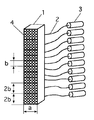
図1は、本発明による光位置検出装置の模式図である。この図において、本発明の光位置検出装置は、受光エリア4を直線状に配置した受光エリア群1と、各受光エリア4に接続された光ファイバ2と、各光ファイバ2に接続された光電変換器3より構成される。
【0010】
各受光エリア4には光ファイバ素線の端面が同一の密度で配置されている。各受光エリア4の光ファイバ素線はそれぞれ束ねられてそれぞれの光ファイバ2となり各々の光電変換器3に接続されている。位置解像度を厳密に必要とする部分の受光エリア4の受光面の寸法を幅a×高さbとすると、厳密に必要としない部分は幅a×高さ(>b)となっている。これにより、受光エリア群1の幅、高さを図3に示す従来の光位置検出装置と同じとすると、見込み視野角と感度は同じで、チャンネル数を大幅に減らすことができる。なお、位置解像度を厳密に必要としない部分の受光エリア4は大きくなるので解像度は落ちるが、この部分は炉頂プロファイル検出開始時の始点の検出および、段差等の大きな位置変動の検出に使用されるだけであるので、概略の位置を捕捉できればよい。各受光エリア4内の光ファイバ素線端面の配置密度は同一なので感度は解像度を必要とする部分と必要としない部分とも同一である。このため解像度が落ちても光位置の捕捉の支障とはならない。
【0011】
受光エリア群1の寸法の一例を説明する。使用する光ファイバ素線の直径をDmmとすると、図1に示す受光エリア4は位置解像度を厳密に必要とする所で、幅a=16Dmm,高さb=2Dmmである。1段16本が2段に配置されている。これにより32本の光ファイバ素線が詰まっている。故に位置解像度を厳密に必要とする中央部では1チャンネルの光ファイバ2は32本の素線から構成されることになる。中央部の受光エリア4は16個よりなり、16チャンネルを構成する。中央部の両側に高さb=2D×2の受光エリア4が一つづづあり、2チャンネルを構成し、その両外側に高さb=2D×3の受光エリア4が二つづつあり4チャンネルを構成する。合計受光エリア4は中央部の16個と端部の6個の合計22個となり、チャンネル数も22となる。受光エリア群1の高さを同じにし、従来のように受光エリア4の大きさを全て同じとすると、端部の6個は16個となり全チャンネル数は32個になる。本発明により同一の見込み視野角と感度を有して10チャンネル減少することができ、光電変換器3の数も10個減少でき、これ以降の回路も簡単になるので光位置検出装置のコストを低減することができる。なお図1とこの実例とは異なっている。
【0012】
【発明の効果】
以上の説明から明らかなように、本発明は各受光エリアの光ファイバ素線端面の配置密度を一定として、各受光エリアの面積に偏差を付けることにより、見込み視野角と感度を変えることなくチャンネル数を減少することができるので構成部品を少なくすることができ、コストを低減することができる。
【図面の簡単な説明】
【図1】本発明による光位置検出装置の模式図である。
【図2】炉頂プロファイル装置の構成を示す図である。
【図3】従来の光位置検出装置の模式図である。
【符号の説明】
1 受光エリア群
2 光ファイバ
3 光電変換器
4 受光エリア
Claims (1)
- 受光エリアを直線状に配置した受光エリア群と、各受光エリアに光ファイバ素線の端面を配置し各受光エリア毎の光ファイバ素線を束ねた光ファイバと、この各光ファイバに接続された光電変換器とを備えた光位置検出装置において、
各受光エリアの光ファイバ素線の端面の配置密度をほぼ同一とし、各受光エリアの面積に偏差を設け、位置解像度に変化を付けたことを特徴とする光位置検出装置。
Priority Applications (1)
| Application Number | Priority Date | Filing Date | Title |
|---|---|---|---|
| JP35118896A JP3661902B2 (ja) | 1996-12-27 | 1996-12-27 | 光位置検出装置 |
Applications Claiming Priority (1)
| Application Number | Priority Date | Filing Date | Title |
|---|---|---|---|
| JP35118896A JP3661902B2 (ja) | 1996-12-27 | 1996-12-27 | 光位置検出装置 |
Publications (2)
| Publication Number | Publication Date |
|---|---|
| JPH10197213A JPH10197213A (ja) | 1998-07-31 |
| JP3661902B2 true JP3661902B2 (ja) | 2005-06-22 |
Family
ID=18415656
Family Applications (1)
| Application Number | Title | Priority Date | Filing Date |
|---|---|---|---|
| JP35118896A Expired - Fee Related JP3661902B2 (ja) | 1996-12-27 | 1996-12-27 | 光位置検出装置 |
Country Status (1)
| Country | Link |
|---|---|
| JP (1) | JP3661902B2 (ja) |
Families Citing this family (1)
| Publication number | Priority date | Publication date | Assignee | Title |
|---|---|---|---|---|
| CN105547180B (zh) * | 2015-11-30 | 2018-06-15 | 浙江工商大学 | 一种反射式光纤束塑料物流托盘弯曲度检测装置 |
-
1996
- 1996-12-27 JP JP35118896A patent/JP3661902B2/ja not_active Expired - Fee Related
Also Published As
| Publication number | Publication date |
|---|---|
| JPH10197213A (ja) | 1998-07-31 |
Similar Documents
| Publication | Publication Date | Title |
|---|---|---|
| EP0757226A3 (en) | Automatic inspection method for contactlessly measuring an offset of a central feature of an object | |
| EP0813165A3 (en) | Fiber-optic block and fingerprint detector using the same | |
| CA2179077A1 (en) | Automatic inspection method for contactlessly measuring an offset of a central feature of an object | |
| JP3661902B2 (ja) | 光位置検出装置 | |
| EP1170937A3 (en) | High speed scanner using multiple sensing devices | |
| JPH08211155A (ja) | X線画像センサ | |
| GB2029153A (en) | Focus detecting device | |
| US5706081A (en) | Apparatus for inspecting surface defects with regularly reflected light and peripherally scattered light | |
| US4948967A (en) | Method for detecting a position receiving a light beam | |
| JPH04215045A (ja) | レーザ検査装置 | |
| US4947449A (en) | Apparatus for simultaneously extracting various types of projection features of an image | |
| JP3441658B2 (ja) | 導波路型イメージセンサ及び導波路型イメージセンサの位置調整方法 | |
| JPS6326156A (ja) | フイルム画像読取り装置 | |
| JPH039205A (ja) | 位置感応光検出器 | |
| JP2585074Y2 (ja) | 走査光ビーム位置検出部構造 | |
| JPS61193560A (ja) | 画像読取装置 | |
| JPH07334597A (ja) | 光学記号読取装置 | |
| JPH0875955A (ja) | 光検出器 | |
| JPH0599621A (ja) | 微少変位センサ | |
| JPS62170905A (ja) | 集光装置 | |
| JPH0348565A (ja) | 画像読取装置 | |
| JPS6347720A (ja) | 画像読み取り装置 | |
| JPH03160758A (ja) | イメージセンサおよびその駆動方法 | |
| EP0624024A1 (en) | Image sensing assembly | |
| JPH0435594A (ja) | スクリーン装置 |
Legal Events
| Date | Code | Title | Description |
|---|---|---|---|
| A977 | Report on retrieval |
Free format text: JAPANESE INTERMEDIATE CODE: A971007 Effective date: 20050228 |
|
| TRDD | Decision of grant or rejection written | ||
| A01 | Written decision to grant a patent or to grant a registration (utility model) |
Free format text: JAPANESE INTERMEDIATE CODE: A01 Effective date: 20050304 |
|
| A61 | First payment of annual fees (during grant procedure) |
Free format text: JAPANESE INTERMEDIATE CODE: A61 Effective date: 20050317 |
|
| FPAY | Renewal fee payment (event date is renewal date of database) |
Free format text: PAYMENT UNTIL: 20080401 Year of fee payment: 3 |
|
| S531 | Written request for registration of change of domicile |
Free format text: JAPANESE INTERMEDIATE CODE: R313531 |
|
| S533 | Written request for registration of change of name |
Free format text: JAPANESE INTERMEDIATE CODE: R313533 |
|
| FPAY | Renewal fee payment (event date is renewal date of database) |
Free format text: PAYMENT UNTIL: 20080401 Year of fee payment: 3 |
|
| R350 | Written notification of registration of transfer |
Free format text: JAPANESE INTERMEDIATE CODE: R350 |
|
| FPAY | Renewal fee payment (event date is renewal date of database) |
Free format text: PAYMENT UNTIL: 20080401 Year of fee payment: 3 |
|
| FPAY | Renewal fee payment (event date is renewal date of database) |
Free format text: PAYMENT UNTIL: 20090401 Year of fee payment: 4 |
|
| FPAY | Renewal fee payment (event date is renewal date of database) |
Free format text: PAYMENT UNTIL: 20090401 Year of fee payment: 4 |
|
| FPAY | Renewal fee payment (event date is renewal date of database) |
Free format text: PAYMENT UNTIL: 20100401 Year of fee payment: 5 |
|
| FPAY | Renewal fee payment (event date is renewal date of database) |
Free format text: PAYMENT UNTIL: 20100401 Year of fee payment: 5 |
|
| FPAY | Renewal fee payment (event date is renewal date of database) |
Free format text: PAYMENT UNTIL: 20110401 Year of fee payment: 6 |
|
| FPAY | Renewal fee payment (event date is renewal date of database) |
Free format text: PAYMENT UNTIL: 20120401 Year of fee payment: 7 |
|
| FPAY | Renewal fee payment (event date is renewal date of database) |
Free format text: PAYMENT UNTIL: 20120401 Year of fee payment: 7 |
|
| FPAY | Renewal fee payment (event date is renewal date of database) |
Free format text: PAYMENT UNTIL: 20130401 Year of fee payment: 8 |
|
| FPAY | Renewal fee payment (event date is renewal date of database) |
Free format text: PAYMENT UNTIL: 20140401 Year of fee payment: 9 |
|
| LAPS | Cancellation because of no payment of annual fees |