JP3666460B2 - Evaporative fuel processing device for internal combustion engine - Google Patents
Evaporative fuel processing device for internal combustion engine Download PDFInfo
- Publication number
- JP3666460B2 JP3666460B2 JP2002039118A JP2002039118A JP3666460B2 JP 3666460 B2 JP3666460 B2 JP 3666460B2 JP 2002039118 A JP2002039118 A JP 2002039118A JP 2002039118 A JP2002039118 A JP 2002039118A JP 3666460 B2 JP3666460 B2 JP 3666460B2
- Authority
- JP
- Japan
- Prior art keywords
- flow rate
- purge
- fuel
- internal combustion
- combustion engine
- Prior art date
- Legal status (The legal status is an assumption and is not a legal conclusion. Google has not performed a legal analysis and makes no representation as to the accuracy of the status listed.)
- Expired - Fee Related
Links
Images



Classifications
-
- F—MECHANICAL ENGINEERING; LIGHTING; HEATING; WEAPONS; BLASTING
- F02—COMBUSTION ENGINES; HOT-GAS OR COMBUSTION-PRODUCT ENGINE PLANTS
- F02M—SUPPLYING COMBUSTION ENGINES IN GENERAL WITH COMBUSTIBLE MIXTURES OR CONSTITUENTS THEREOF
- F02M25/00—Engine-pertinent apparatus for adding non-fuel substances or small quantities of secondary fuel to combustion-air, main fuel or fuel-air mixture
- F02M25/08—Engine-pertinent apparatus for adding non-fuel substances or small quantities of secondary fuel to combustion-air, main fuel or fuel-air mixture adding fuel vapours drawn from engine fuel reservoir
- F02M25/0836—Arrangement of valves controlling the admission of fuel vapour to an engine, e.g. valve being disposed between fuel tank or absorption canister and intake manifold
-
- F—MECHANICAL ENGINEERING; LIGHTING; HEATING; WEAPONS; BLASTING
- F02—COMBUSTION ENGINES; HOT-GAS OR COMBUSTION-PRODUCT ENGINE PLANTS
- F02D—CONTROLLING COMBUSTION ENGINES
- F02D41/00—Electrical control of supply of combustible mixture or its constituents
- F02D41/0025—Controlling engines characterised by use of non-liquid fuels, pluralities of fuels, or non-fuel substances added to the combustible mixtures
- F02D41/003—Adding fuel vapours, e.g. drawn from engine fuel reservoir
- F02D41/0032—Controlling the purging of the canister as a function of the engine operating conditions
-
- F—MECHANICAL ENGINEERING; LIGHTING; HEATING; WEAPONS; BLASTING
- F02—COMBUSTION ENGINES; HOT-GAS OR COMBUSTION-PRODUCT ENGINE PLANTS
- F02D—CONTROLLING COMBUSTION ENGINES
- F02D41/00—Electrical control of supply of combustible mixture or its constituents
- F02D41/0025—Controlling engines characterised by use of non-liquid fuels, pluralities of fuels, or non-fuel substances added to the combustible mixtures
- F02D41/003—Adding fuel vapours, e.g. drawn from engine fuel reservoir
- F02D41/0032—Controlling the purging of the canister as a function of the engine operating conditions
- F02D41/004—Control of the valve or purge actuator, e.g. duty cycle, closed loop control of position
-
- F—MECHANICAL ENGINEERING; LIGHTING; HEATING; WEAPONS; BLASTING
- F02—COMBUSTION ENGINES; HOT-GAS OR COMBUSTION-PRODUCT ENGINE PLANTS
- F02D—CONTROLLING COMBUSTION ENGINES
- F02D41/00—Electrical control of supply of combustible mixture or its constituents
- F02D41/20—Output circuits, e.g. for controlling currents in command coils
- F02D2041/202—Output circuits, e.g. for controlling currents in command coils characterised by the control of the circuit
- F02D2041/2024—Output circuits, e.g. for controlling currents in command coils characterised by the control of the circuit the control switching a load after time-on and time-off pulses
- F02D2041/2027—Control of the current by pulse width modulation or duty cycle control
-
- F—MECHANICAL ENGINEERING; LIGHTING; HEATING; WEAPONS; BLASTING
- F02—COMBUSTION ENGINES; HOT-GAS OR COMBUSTION-PRODUCT ENGINE PLANTS
- F02M—SUPPLYING COMBUSTION ENGINES IN GENERAL WITH COMBUSTIBLE MIXTURES OR CONSTITUENTS THEREOF
- F02M25/00—Engine-pertinent apparatus for adding non-fuel substances or small quantities of secondary fuel to combustion-air, main fuel or fuel-air mixture
- F02M25/08—Engine-pertinent apparatus for adding non-fuel substances or small quantities of secondary fuel to combustion-air, main fuel or fuel-air mixture adding fuel vapours drawn from engine fuel reservoir
Landscapes
- Engineering & Computer Science (AREA)
- Chemical & Material Sciences (AREA)
- Combustion & Propulsion (AREA)
- Mechanical Engineering (AREA)
- General Engineering & Computer Science (AREA)
- Supplying Secondary Fuel Or The Like To Fuel, Air Or Fuel-Air Mixtures (AREA)
- Electrical Control Of Air Or Fuel Supplied To Internal-Combustion Engine (AREA)
- Combined Controls Of Internal Combustion Engines (AREA)
Description
【0001】
【発明の属する技術分野】
本発明は、内燃機関の蒸発燃料処理装置に関する。
【0002】
【従来の技術】
従来の内燃機関の蒸発燃料処理装置では、燃料タンク等で発生する蒸発燃料をキャニスタに一時的に吸着し、該吸着した蒸発燃料を所定の機関運転条件で離脱させてパージ用空気と混合したパージガスを、パージ制御弁で流量制御しつつ機関の吸気系へ吸引処理することによって、蒸発燃料の外気への蒸散を防止するようにしている(特開平5−215020号等参照)。
【0003】
近年、蒸発燃料蒸散防止の規制強化に伴ない、キャニスタ容量が大型化されると共に、時間当たりのパージ処理量の増大が要求されている。
【0004】
【発明が解決しようとする課題】
一般的なパージ制御弁は開閉をデューティ制御するものが用いられるが、上記パージ処理量の増大要求に伴い、パージ制御弁を大型化すると、微小流量域のパージ開始時の流量段差が大きくなり、アイドル時等吸入空気量が少ない領域で微小なパージガス流量制御を行うと、空燃比変動が大きくなって運転性不良が発生しやすくなる。
【0005】
本発明は、このような従来の課題に着目してなされたもので、大型化されたパージ制御弁を用いてもパージ制御開始時の流量段差を解消しつつ、耐久性を確保できるようにした内燃機関の蒸発燃料処理装置を提供することを目的とする。
【0006】
【課題を解決するための手段】
このため、請求項1に係る発明は、
蒸発燃料を含むパージガスを、開閉がデューティ制御されるパージ制御弁によって流量制御しつつ機関の吸気系に吸入処理する内燃機関の蒸発燃料処理装置において、
前記パージ制御弁のデューティ制御における駆動周波数を、パージガスの低流量制御時は高周波数、高流量制御時は低周波数に設定すると共に、前記駆動周波数切り換え直後のデューティ値を、パージガス流量が切り換え直前の値以下となるように設定することを特徴とする。
【0007】
請求項1に係る発明によると、
大容量のパージ制御弁を用いつつパージガスの低流量制御時は高周波数とすることで、パージ開始時の空燃比段差を抑制しつつ安定した制御性を確保できる。また、高流量域では駆動周波数を低周波数とすることで、開閉回数を減少させて耐久性を確保できる。
【0008】
また、パージ制御中は燃料噴射量が既に減量補正され、駆動周波数切り換え直後にパージガス流量が増大すると、前記減量補正量がリミット値を越えてしまい空燃比が過剰リッチとなる可能性がある。
【0009】
そこで、パージガス流量が切り換え直前の値以下となるように駆動周波数切り換え直後のデューティ値を少なめに設定することにより、上記空燃比が過剰リッチとなることを防止でき、安定した運転性を確保できる。
また、請求項2に係る発明は、
前記駆動周波数切り換え時に、該切り換え前のパージガス流量とパージ制御弁のデューティ値に基づいて、切り換え後のデューティ値を設定することを特徴とする。
【0010】
請求項2に係る発明によると、
パージ制御弁の流量特性(流量−デューティ値)のバラツキを考慮して切り換え後のデューティ値を設定でき、駆動周波数切換による流量誤差を少なくでき、空燃比変動を抑制できる。
また、請求項3に係る発明は、
前記駆動周波数切り換え前のパージガス流量を、パージガス中の蒸発燃料濃度と燃料噴射弁から機関に噴射される燃料噴射量の補正値とに基づいて算出することを特徴とする。
【0011】
請求項3に係る発明によると、
パージガス流量を流量センサで測定する場合には、蒸発燃料濃度に応じてパージガスの比重の変化や科学的な変化を伴うことにより測定結果に誤差を生じるが、パージガス中の蒸発燃料濃度と燃料噴射量の補正値に基づいて算出することにより、このような誤差が無く、高精度に流量を算出できる。
【0012】
また、請求項4に係る発明は、
前記駆動周波数を高周波数から低周波数に切り換えるときは、低周波数におけるパージ制御弁流量特性の最大傾き(傾き:流量/デューティ値)を用いた変換によりデューティ値を設定することを特徴とする。
請求項4に係る発明によると、
低周波数におけるデューティ値を、パージ制御弁流量特性の最大傾きを用いた変換により設定することにより、部品バラツキを考えても燃料噴射量の減少補正量の限界値を超えることなく補正が可能となり、燃焼性を良好に維持できる。
【0013】
また、請求項5に係る発明は、
前記駆動周波数を、パージ制御弁の流量特性における変極点に応じて予め設定された目標流量で切り換えることを特徴とする。
請求項5に係る発明によると、パージ制御弁の安定した流量特性を示す範囲を使用することができ、制御精度が向上する。
【0014】
また、請求項6に係る発明は、パージ制御弁は、燃料タンクから発生する蒸発燃料を一時的に吸着するキャニスタと機関の吸気系とを接続するパージ通路に介装されていることを特徴とする。
請求項6に係る発明によると、燃料タンクから発生して一時的にキャニスタに吸着される蒸発燃料の量が最も多く、そのパージ通路に介装されたパージ制御弁の制御に適用すると、最も効果的である。
【0015】
【発明の実施の形態】
以下に本発明の実施の形態を説明する。
図1は、実施の形態において蒸発燃料処理装置を含んで構成される車両用内燃機関のシステム構成図である。
この図1において、車両に搭載される内燃機関1の各気筒の燃焼室には、エアクリーナ2,吸気管3,電子制御式スロットル弁4を介して空気が各気筒に吸入される。
【0016】
前記電子制御式スロットル弁4は、モータ等のアクチュエータによってスロットル弁の弁体を開閉駆動するよう構成されたシステムであるが、アクセルペダルに連動するスロットル弁であってもよい。
また、各気筒の燃焼室内に燃料(ガソリン)を直接噴射するように、電磁式の燃料噴射弁5が設けられているが、吸気通路に噴射する燃料噴射弁であってもよい。
【0017】
前記燃料噴射弁5は、コントロールユニット20から出力される噴射パルス信号によりソレノイドに通電されて開弁し、所定圧力に調圧された燃料を噴射する。そして、燃焼室内に形成された混合気は、コントロールユニット20からの点火信号に基づき制御される点火栓6により着火燃焼する。
但し、内燃機関1を上記の直接噴射式ガソリン機関に限定するものではなく、吸気ポートに燃料を噴射する構成の機関であっても良い。
【0018】
内燃機関1からの排気は排気管7を介して排出され、排気管7には排気浄化用の触媒8が介装されている。
また、燃料タンク9から発生する蒸発燃料を処理すべく、蒸発燃料処理装置が設けられている。
キャニスタ10は、密閉容器内に活性炭などの吸着剤11を充填したもので、燃料タンク9からの蒸発燃料導入管12が接続されている。従って、内燃機関1の停止中などに燃料タンク9にて発生した蒸発燃料は、蒸発燃料導入管12を通って、キャニスタ10に導かれ、ここに吸着捕集される。
【0019】
また、キャニスタ10には、新気導入口13が形成されると共に、パージ配管14が導出されている。前記パージ配管14には、コントロールユニット20からの制御信号によって開閉がデューティ制御されるパージ制御弁15と、該パージ配管14内を流れるパージガスの濃度を検出する濃度センサ16が介装されている。
【0020】
上記構成において、パージ制御弁15が開制御されると、内燃機関1の吸入負圧がキャニスタ10に作用する結果、新気導入口13から導入される空気によってキャニスタ10の吸着剤11に吸着されていた蒸発燃料がパージされ、このパージされた蒸発燃料を含むパージガスが、前記パージ配管14を通って吸気管3の電子制御式スロットル弁4下流側に吸入され、この後、内燃機関1の燃焼室内で燃焼される。
【0021】
コントロールユニット20は、CPU、ROM、RAM、A/D変換器及び入出力インターフェイス等を含んで構成されるマイコンを備え、各種センサからの入力信号を受け、これに基づいて演算処理して、燃料噴射弁5,点火栓6及びパージ制御弁15などの作動を制御する。
前記各種センサとしては、内燃機関1のクランク角を検出するクランク角センサ21、気筒判別信号を出力するカムセンサ22が設けられている。ここで、前記クランク角センサ21からの検出信号に基づき機関回転速度Neが演算される。
【0022】
この他、吸気管3の電子制御式スロットル弁4上流で吸入空気流量Qaを検出するエアフローメータ23、アクセルペダルの踏込み量(アクセル開度)APSを検出するアクセルセンサ24、電子制御式スロットル弁4の開度TVOを検出するスロットルセンサ25、機関1の冷却水温Twを検出する水温センサ26、排気中の酸素濃度に基づいて排気空燃比を検出する空燃比センサ27、車速VSPを検出する車速センサ28などが設けられている。
【0023】
尚、前記空燃比センサ27で検出される排気空燃比を目標空燃比に一致させるべく燃料噴射量を補正するための空燃比フィードバック係数を設定する空燃比フィードバック制御が、所定の空燃比フィードバック条件下で行われる構成となっており、前記キャニスタ10からの蒸発燃料のパージは、前記空燃比フィードバック制御が行われていることを条件として実行されるようになっている。
【0024】
以上のように構成された内燃機関の蒸発燃料処理装置において、本発明では、前記パージ制御弁15のデューティ制御を、流量域によって周波数、デューティ値を切り換えつつ実行する。
以下に、上記本発明に係るパージ制御弁15のデューティ制御を、図2のフローチャートに従って説明する。
【0025】
ステップ1では、アイドルでパージを開始する状態か否かを判定する。
アイドルでパージを開始する状態であると判定されたときは、ステップ2へ進み、パージ制御弁15の駆動周波数を高周波数、具体的には40Hzに設定する。
ステップ3では、前記駆動周波数でデューティ制御を開始する。
【0026】
ステップ4では、濃度センサ16によって検出されるパージガス濃度と燃料噴射量補正係数とに基づいて、パージガスの流量を算出する。
図3は、上記ステップ4における蒸発燃料のパージガス流量演算ルーチンのフローチャートを示す。
ステップ11では、機関回転速度Ne、吸入空気量Qaを読み込む。
【0027】
ステップ12では、前記機関回転速度Ne、吸入空気量Qaとに基づいて、基本燃料噴射量Tpを算出ないしマップ参照する。
ステップ13では、燃料噴射量の補正割合A%(空燃比フィードバック補正係数αの補正割合)を算出して読み込む。
ステップ14では、パージ影響分による減量燃料量Pを次式により演算する。
【0028】
P=Tp×A/100
ステップ15では、パージガス濃度Mを読み込む。
ステップ16では、パージガス流量Qpを、次式によって演算する。
Qp=k×P×Ne×(気筒数/2)/M
k:定数
図2に戻って、ステップ5では、ステップ16で推定されたパージガス流量が目標値α(L/min)に到達したか否かを判定し、到達したときに、ステップ6へ進む。
【0029】
ステップ6では、そのときのパージ制御弁15の駆動時間a(ms)を算出する。この駆動時間aは、無効時間によってばらつき無効時間が大きいほど駆動時間aが増大する。
ステップ7では、前記駆動時間a(ms)に対応する低周波数、具体的には10Hz駆動でのデューティ値B0%を演算する。該デューティ値B0%は、前記40Hzでのデューティ値A%に周波数比(10/40)を乗じた値(B0=A/4)となる。
【0030】
ステップ8では、10Hzの駆動で同一の流量α(L/min)を得るために、前記デューティ値B0%に加算されるべき増加分C%を以下のように算出する。
10Hz駆動でデューティ値B0%で得られるパージガス流量は、目標値α(L/min)に周波数比(10/40)を乗じた値α/4(L/min)となり、不足分3α/4(L/min)を得るのに必要なC%を、図4に示される流量特性(流量−デューティ値)において、前記不足分3α/4(L/min)に最大傾きt(流量/デューティ値)で除算して算出する。
【0031】
ステップ9では、最終的に10Hzの駆動周波数におけるデューティ値Bを、次式のように算出する。
B=B0+C=A/4+(3α/4)/t
ここで、前記パージガス流量の不足分に対応するデューティ値を、パージ制御弁の流量特性の最大傾きtで除算して算出するようにしたため、実際の不足分より少なめに算出されることになる。
【0032】
ステップ10では、パージ制御弁15の駆動周波数を高周波数(40Hz)から低周波数(10Hz)に切り換えると共に、デューティ値をA%からB%に切り換える。
このように、パージガス流量の低流量域ではパージ制御弁15の駆動周波数を高周波数とすることで、パージ開始時の空燃比段差を抑制できるので安定した運転性を確保でき、高流量域では駆動周波数を低周波数とすることで、流量精度と耐久性を確保できる。
【0033】
また、切り換え前のパージガス流量とパージ制御弁のデューティ値に基づいて(実駆動時間aの算出を介して)、切り換え後のデューティ値を設定するようにしたので、パージ制御弁の流量特性(流量−デューティ値)のバラツキがあっても駆動周波数切換による流量誤差を少なくできる。
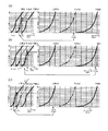
図4は上記のことを示す。すなわち、パージ制御弁は流量特性の中央値(基準値)に対し、バラツキの上限と下限を有し、(A)のバラツキの無い中央値であるときは勿論、(B)のバラツキが下限にあるとき、及び(C)のバラツキが上限にあるときでも、それぞれ切り換え前の流量α,α',α”(L/min)に近い切り換え後の流量β,β',β”(L/min)を得ることができる。
【0034】
因みに、上記のような切り換え前のパージ流量とデューティ値とに基づくことなく、流量特性が中央値にあることを想定して作成したマップを参照して、駆動周波数を高周波数(40Hz)から低周波数(10Hz)に切り換えた場合には、パージ制御弁の実際の流量特性のバラツキが下限である場合は、(B)でγ'で示すように実質的に流量0となってしまい、逆に、パージ制御弁の実際の流量特性のバラツキが上限である場合は、(B)でγ”で示すように、極めて大きな流量となってしまう。
【0035】
さらに、高周波数から低周波数への切り換えに際して、前記流量不足分に対応するデューティ値C%を、パージ制御弁の流量特性の最大傾きtを用いて少なめに算出するようにしたため[図4、α,α',α”→β,β',β”(<α,α',α”)]、切り換え時に空燃比が過剰リッチとなることを確実に防止でき、失火発生(運転性悪化)を防止できる。
【0036】
すなわち、燃料噴射弁5からの燃料噴射量は、図5に示すように、中央値を100%として例えば±25%に補正可能領域を作り、センサ系のノイズバラツキを拾ってしまい誤った燃料噴射量が算出された場合にも、そのまま誤った燃料噴射量が設定されないように、リミッタを超えての設定を行わないようにしている。
【0037】
該燃料噴射量の設定は、前記空燃比センサ27で検出される空燃比の信号に基づいてフィードバック制御され、パージを行わない場合には補正値は基本的に0であり、100%を中心に振れるようになっている。
ここで、不確定な因子として、パージ制御弁の駆動周波数切り換えによりパージ量が増加方向に急激に変化すると、約5%分は減算することは可能であるが、補正幅上限となり、燃料噴射量を補正することができず空燃比がリッチとなる。このリッチ度合いが高くなると機関が失火する問題が発生する。
【0038】
これに対し、上記実施形態のように、パージガス流量が減少するように変化させる場合には、流量が減少した分だけ燃料噴射量を増量する方向(100%に戻る方向)に補正を行うだけであり、直ちに燃料噴射量を補正しなおすことは可能であり、上記過剰リッチを抑制しつつ、空燃比を適正値に維持できるのである。なお、本発明は、キャニスタからの蒸発燃料処理に適用するのが最も効果的であるが、クランクケース等に溜まる蒸発燃料を含むブローバイガスを機関吸気系に吸引処理する制御弁によるパージ制御等にも適用できる。
【図面の簡単な説明】
【図1】本発明に係る内燃機関の排気浄化装置のシステム構成を示す図。
【図2】実施形態におけるパージ制御のメインルーチンのフローチャート。
【図3】同上パージ制御においてパージガス流量を算出するサブルーチンのフローチャート。
【図4】同上実施形態においてパージ制御弁の駆動周波数を切り換えたときの変化を示す図。
【図5】同上パージ制御時における燃料噴射弁からの燃料噴射量の変化を示す図。
【符号の説明】
1 内燃機関
5 燃料噴射弁
8 触媒
9 燃料タンク
10 キャニスタ
11 吸着剤
12 蒸発燃料導入管
13 新気導入口
14 パージ配管
15 パージ制御弁
16 濃度センサ
20 コントロールユニット
21 クランク角センサ
27 空燃比センサ[0001]
BACKGROUND OF THE INVENTION
The present invention relates to an evaporated fuel processing apparatus for an internal combustion engine.
[0002]
[Prior art]
In a conventional evaporative fuel treatment apparatus for an internal combustion engine, a purge gas in which evaporative fuel generated in a fuel tank or the like is temporarily adsorbed to a canister, and the adsorbed evaporative fuel is released under predetermined engine operating conditions and mixed with purge air. The fuel is sucked into the intake system of the engine while controlling the flow rate with a purge control valve, thereby preventing evaporation of evaporated fuel to the outside air (see Japanese Patent Application Laid-Open No. 5-215020 etc.).
[0003]
In recent years, with the tightening of regulations for preventing evaporation of evaporated fuel, the capacity of canisters has been increased, and an increase in the amount of purge processing per hour has been demanded.
[0004]
[Problems to be solved by the invention]
A general purge control valve with duty control for opening and closing is used. However, if the purge control valve is enlarged in response to the request for increasing the purge processing amount, the flow rate step at the start of purge in a minute flow rate region becomes large. When a small purge gas flow rate control is performed in a region where the intake air amount is small, such as during idling, fluctuations in the air-fuel ratio become large, and drivability is likely to occur.
[0005]
The present invention has been made paying attention to such a conventional problem, and it is possible to ensure durability while eliminating a flow level difference at the start of purge control even when a purge control valve having a larger size is used. An object of the present invention is to provide a fuel vapor processing apparatus for an internal combustion engine.
[0006]
[Means for Solving the Problems]
For this reason, the invention according to claim 1
In an evaporative fuel processing apparatus for an internal combustion engine for performing a suction process on a purge gas containing evaporative fuel into an intake system of the engine while controlling a flow rate by a purge control valve whose duty is controlled to open and close,
The drive frequency in the duty control of the purge control valve is set to a high frequency at the time of purge gas low flow control and to a low frequency at the time of high flow control , and the duty value immediately after switching the drive frequency is set immediately before the purge gas flow rate is switched. It is characterized in that it is set to be less than the value .
[0007]
According to the invention of claim 1,
By using a high frequency during low flow control of purge gas while using a large-capacity purge control valve, stable controllability can be secured while suppressing the air-fuel ratio step at the start of purge. In addition, by setting the drive frequency to a low frequency in the high flow rate region, the number of opening and closing operations can be reduced to ensure durability.
[0008]
Further, if the fuel injection amount is already corrected to decrease during the purge control and the purge gas flow rate increases immediately after switching the drive frequency, the amount of decrease correction may exceed the limit value, and the air-fuel ratio may become excessively rich.
[0009]
Therefore, by setting the duty value immediately after switching the drive frequency so that the purge gas flow rate becomes equal to or less than the value immediately before switching, the air-fuel ratio can be prevented from becoming excessively rich, and stable operability can be secured.
The invention according to claim 2
When the drive frequency is switched, the duty value after switching is set based on the purge gas flow rate before switching and the duty value of the purge control valve.
[0010]
According to the invention of claim 2 ,
The duty value after switching can be set in consideration of variations in the flow rate characteristics (flow rate-duty value) of the purge control valve, the flow rate error due to switching of the drive frequency can be reduced, and fluctuations in the air-fuel ratio can be suppressed.
The invention according to
The purge gas flow rate before the switching of the driving frequency is calculated based on a concentration of evaporated fuel in the purge gas and a correction value of the fuel injection amount injected from the fuel injection valve to the engine.
[0011]
According to the invention of
When the purge gas flow rate is measured with a flow sensor, an error occurs in the measurement result due to a change in specific gravity or scientific change of the purge gas depending on the evaporated fuel concentration, but the evaporated fuel concentration in the purge gas and the fuel injection amount By calculating based on this correction value, the flow rate can be calculated with high accuracy without such an error.
[0012]
The invention according to claim 4
When the drive frequency is switched from a high frequency to a low frequency, the duty value is set by conversion using the maximum gradient (gradient: flow rate / duty value) of the purge control valve flow rate characteristic at the low frequency.
According to the invention of claim 4 ,
By setting the duty value at the low frequency by conversion using the maximum slope of the purge control valve flow rate characteristic, it becomes possible to correct without exceeding the limit value of the fuel injection amount decrease correction amount, even if component variation is considered, Good flammability can be maintained.
[0013]
The invention according to
The drive frequency is switched at a target flow rate set in advance according to an inflection point in the flow rate characteristic of the purge control valve.
According to the invention which concerns on
[0014]
The invention according to claim 6 is characterized in that the purge control valve is interposed in a purge passage connecting a canister for temporarily adsorbing the evaporated fuel generated from the fuel tank and an intake system of the engine. To do.
According to the sixth aspect of the present invention, the amount of evaporated fuel generated from the fuel tank and temporarily adsorbed to the canister is the largest, and is most effective when applied to control of the purge control valve interposed in the purge passage. Is.
[0015]
DETAILED DESCRIPTION OF THE INVENTION
Embodiments of the present invention will be described below.
FIG. 1 is a system configuration diagram of an internal combustion engine for a vehicle that includes an evaporative fuel processing device in an embodiment.
In FIG. 1, air is sucked into each cylinder through an air cleaner 2, an
[0016]
The electronically controlled throttle valve 4 is a system configured to open and close the throttle valve body by an actuator such as a motor, but may be a throttle valve interlocked with an accelerator pedal.
Further, although the electromagnetic
[0017]
The
However, the internal combustion engine 1 is not limited to the above direct injection gasoline engine, and may be an engine configured to inject fuel into the intake port.
[0018]
Exhaust gas from the internal combustion engine 1 is discharged through an
An evaporative fuel processing device is provided to process evaporative fuel generated from the
The
[0019]
Further, a
[0020]
In the above configuration, when the
[0021]
The
As the various sensors, a
[0022]
In addition, an
[0023]
The air-fuel ratio feedback control for setting the air-fuel ratio feedback coefficient for correcting the fuel injection amount so that the exhaust air-fuel ratio detected by the air-
[0024]
In the fuel vapor processing apparatus for an internal combustion engine configured as described above, in the present invention, the duty control of the
Hereinafter, the duty control of the
[0025]
In step 1, it is determined whether or not it is in a state of starting purge at idle.
When it is determined that the purge is started in the idle state, the process proceeds to step 2, and the drive frequency of the
In
[0026]
In step 4, the purge gas flow rate is calculated based on the purge gas concentration detected by the
FIG. 3 shows a flowchart of the routine for calculating the purge gas flow rate of the evaporated fuel in step 4 above.
In step 11, the engine speed Ne and the intake air amount Qa are read.
[0027]
In step 12, the basic fuel injection amount Tp is calculated or referred to on the map based on the engine speed Ne and the intake air amount Qa.
In
In
[0028]
P = Tp × A / 100
In
In
Qp = k × P × Ne × (number of cylinders / 2) / M
k: Constant Returning to FIG. 2, in
[0029]
In step 6, the drive time a (ms) of the
In
[0030]
In
The purge gas flow rate obtained with a duty value B0% by driving at 10 Hz becomes a value α / 4 (L / min) obtained by multiplying the target value α (L / min) by the frequency ratio (10/40), and the shortage 3α / 4 ( C /% required to obtain (L / min) is the maximum slope t (flow rate / duty value) in the shortage 3α / 4 (L / min) in the flow rate characteristic (flow rate-duty value) shown in FIG. Divide by to calculate.
[0031]
In
B = B0 + C = A / 4 + (3α / 4) / t
Here, since the duty value corresponding to the shortage of the purge gas flow rate is calculated by dividing by the maximum gradient t of the flow rate characteristic of the purge control valve, it is calculated to be smaller than the actual shortage amount.
[0032]
In
Thus, by setting the drive frequency of the
[0033]
Further, since the duty value after switching is set based on the purge gas flow rate before switching and the duty value of the purge control valve (via calculation of the actual driving time a), the flow rate characteristic (flow rate) of the purge control valve is set. -Even if there is a variation in (duty value), the flow rate error due to switching of the drive frequency can be reduced.
FIG. 4 illustrates the above. That is, the purge control valve has an upper limit and a lower limit of variation with respect to the median value (reference value) of the flow rate characteristic, and of course, when (A) is a median value without variation, (B) variation is at the lower limit. In some cases and even when the variation in (C) is at the upper limit, the flow rates β, β ′, β ″ (L / min) after switching close to the flow rates α, α ′, α ″ (L / min) before switching, respectively. ) Can be obtained.
[0034]
By the way, referring to a map created assuming that the flow rate characteristic is at the median value without being based on the purge flow rate and duty value before switching as described above, the drive frequency is reduced from a high frequency (40 Hz) to a low frequency. When switching to the frequency (10 Hz), if the variation in the actual flow rate characteristic of the purge control valve is the lower limit, the flow rate is substantially zero as shown by γ ′ in (B), and conversely When the actual flow characteristic variation of the purge control valve is the upper limit, the flow rate becomes extremely large as indicated by γ ″ in (B).
[0035]
Furthermore, when switching from high frequency to low frequency, the duty value C% corresponding to the shortage of the flow rate is calculated to be smaller using the maximum gradient t of the flow rate characteristic of the purge control valve [FIG. 4, α , Α ′, α ″ → β, β ′, β ″ (<α, α ′, α ″)], it is possible to reliably prevent the air-fuel ratio from becoming excessively rich at the time of switching, and to prevent misfire (deterioration of driving performance). Can be prevented.
[0036]
That is, as shown in FIG. 5, the fuel injection amount from the
[0037]
The setting of the fuel injection amount is feedback-controlled based on an air-fuel ratio signal detected by the air-
Here, as an uncertain factor, if the purge amount suddenly changes in the increasing direction by switching the drive frequency of the purge control valve, it is possible to subtract about 5%, but it becomes the upper limit of the correction width, and the fuel injection amount Cannot be corrected, and the air-fuel ratio becomes rich. When this rich degree becomes high, the problem that the engine misfires occurs.
[0038]
On the other hand, when the purge gas flow rate is changed so as to decrease as in the above embodiment, the correction is made only in the direction in which the fuel injection amount is increased (the direction returning to 100%) by the reduced flow rate. Yes, the fuel injection amount can be immediately corrected again, and the air-fuel ratio can be maintained at an appropriate value while suppressing the excessive richness. The present invention is most effective when applied to the process of evaporating fuel from the canister, but for purging control by a control valve for sucking blowby gas containing evaporative fuel accumulated in a crankcase or the like into the engine intake system. Is also applicable.
[Brief description of the drawings]
FIG. 1 is a diagram showing a system configuration of an exhaust gas purification apparatus for an internal combustion engine according to the present invention.
FIG. 2 is a flowchart of a main routine of purge control in the embodiment.
FIG. 3 is a flowchart of a subroutine for calculating a purge gas flow rate in the purge control.
FIG. 4 is a diagram showing a change when the drive frequency of the purge control valve is switched in the embodiment.
FIG. 5 is a diagram showing a change in fuel injection amount from a fuel injection valve during purge control.
[Explanation of symbols]
DESCRIPTION OF SYMBOLS 1
Claims (6)
前記パージ制御弁のデューティ制御における駆動周波数を、パージガスの低流量制御時は高周波数、高流量制御時は低周波数に設定すると共に、前記駆動周波数切り換え直後のデューティ値を、パージガス流量が切り換え直前の値以下となるように設定することを特徴とする内燃機関の蒸発燃料処理装置。In an evaporative fuel processing apparatus for an internal combustion engine for performing a suction process on an intake system of an engine while controlling a flow rate of a purge gas containing the evaporated fuel by a purge control valve whose duty is controlled to open and close,
The drive frequency in the duty control of the purge control valve is set to a high frequency at the time of purge gas low flow control, and to a low frequency at the time of high flow control , and the duty value immediately after the drive frequency is switched An evaporative fuel processing apparatus for an internal combustion engine, wherein the evaporative fuel processing apparatus is set to be equal to or less than a value .
Priority Applications (2)
| Application Number | Priority Date | Filing Date | Title |
|---|---|---|---|
| JP2002039118A JP3666460B2 (en) | 2002-02-15 | 2002-02-15 | Evaporative fuel processing device for internal combustion engine |
| US10/342,215 US6729312B2 (en) | 2002-02-15 | 2003-01-15 | Fuel vapor treatment apparatus |
Applications Claiming Priority (1)
| Application Number | Priority Date | Filing Date | Title |
|---|---|---|---|
| JP2002039118A JP3666460B2 (en) | 2002-02-15 | 2002-02-15 | Evaporative fuel processing device for internal combustion engine |
Publications (2)
| Publication Number | Publication Date |
|---|---|
| JP2003239812A JP2003239812A (en) | 2003-08-27 |
| JP3666460B2 true JP3666460B2 (en) | 2005-06-29 |
Family
ID=27678225
Family Applications (1)
| Application Number | Title | Priority Date | Filing Date |
|---|---|---|---|
| JP2002039118A Expired - Fee Related JP3666460B2 (en) | 2002-02-15 | 2002-02-15 | Evaporative fuel processing device for internal combustion engine |
Country Status (2)
| Country | Link |
|---|---|
| US (1) | US6729312B2 (en) |
| JP (1) | JP3666460B2 (en) |
Cited By (1)
| Publication number | Priority date | Publication date | Assignee | Title |
|---|---|---|---|---|
| JP2018066353A (en) * | 2016-10-21 | 2018-04-26 | マツダ株式会社 | Evaporation fuel treatment device for engine |
Families Citing this family (16)
| Publication number | Priority date | Publication date | Assignee | Title |
|---|---|---|---|---|
| JP3560156B2 (en) * | 2001-05-22 | 2004-09-02 | 本田技研工業株式会社 | Evaporative fuel control system for internal combustion engine |
| US6959696B2 (en) * | 2002-04-12 | 2005-11-01 | Briggs & Stratton Corporation | Internal combustion engine evaporative emission control system |
| RU2267027C2 (en) * | 2004-01-30 | 2005-12-27 | Открытое акционерное общество "АВТОВАЗ" | Adsorber |
| JP2005248895A (en) * | 2004-03-05 | 2005-09-15 | Toyota Motor Corp | Control device for internal combustion engine |
| RU2274765C2 (en) * | 2004-06-08 | 2006-04-20 | Евгений Васильевич Лысенко | Adsorber of fuel evaporation control system |
| US7185640B2 (en) * | 2004-11-05 | 2007-03-06 | Briggs & Stratton Corporation | Integrated fuel tank and vapor containment system |
| US7086390B2 (en) * | 2004-11-05 | 2006-08-08 | Briggs & Stratton Corporation | Integrated fuel tank and vapor containment system |
| US7435289B2 (en) * | 2005-09-27 | 2008-10-14 | Briggs & Stratton Corporation | Integrated air cleaner and vapor containment system |
| JP4523555B2 (en) * | 2006-01-30 | 2010-08-11 | 株式会社日本自動車部品総合研究所 | Evaporative fuel processing device for internal combustion engine |
| US7281525B2 (en) * | 2006-02-27 | 2007-10-16 | Briggs & Stratton Corporation | Filter canister family |
| US7401600B1 (en) * | 2007-01-30 | 2008-07-22 | Gm Global Technology Operations, Inc. | Purge flow control to reduce air/fuel ratio imbalance |
| US9316166B2 (en) * | 2013-03-15 | 2016-04-19 | GM Global Technology Operations LLC | System and method for controlling an operating frequency of a purge valve to improve fuel distribution to cylinders of an engine |
| US20160131055A1 (en) * | 2014-08-29 | 2016-05-12 | GM Global Technology Operations LLC | System and method for determining the reid vapor pressure of fuel combusted by an engine and for controlling fuel delivery to cylinders of the engine based on the reid vapor pressure |
| KR101896324B1 (en) * | 2016-09-19 | 2018-09-07 | 현대자동차 주식회사 | Apparatus and method for purging fuel vapor |
| JP7027942B2 (en) * | 2018-02-22 | 2022-03-02 | トヨタ自動車株式会社 | Evaporative fuel processing equipment |
| KR102364922B1 (en) * | 2020-10-12 | 2022-02-18 | 주식회사 현대케피코 | Method for Compensating Flow Deviation 0f PCSV and Fuel Evaporation Gas Control System for Vehicle Thereof |
Family Cites Families (11)
| Publication number | Priority date | Publication date | Assignee | Title |
|---|---|---|---|---|
| JPH05215020A (en) | 1991-12-09 | 1993-08-24 | Honda Motor Co Ltd | Canister purge controller |
| JP2860851B2 (en) | 1993-02-05 | 1999-02-24 | 株式会社ユニシアジェックス | Evaporative fuel control system for internal combustion engine |
| JP3323577B2 (en) | 1993-03-29 | 2002-09-09 | マツダ株式会社 | Evaporative fuel processor for engine |
| JPH07139440A (en) | 1993-11-18 | 1995-05-30 | Unisia Jecs Corp | Evaporative fuel processor for engine |
| JPH0874682A (en) * | 1994-09-01 | 1996-03-19 | Toyota Motor Corp | Evaporative fuel processor |
| JPH08261074A (en) | 1995-03-24 | 1996-10-08 | Unisia Jecs Corp | Evaporative fuel control system for internal combustion engine |
| US5746187A (en) * | 1995-08-11 | 1998-05-05 | Mazda Motor Corporation | Automotive engine control system |
| JP3277767B2 (en) * | 1995-09-22 | 2002-04-22 | 日産自動車株式会社 | Evaporative fuel treatment system for internal combustion engine |
| JP3500867B2 (en) * | 1996-01-19 | 2004-02-23 | トヨタ自動車株式会社 | Evaporative fuel processing system for a multi-cylinder internal combustion engine |
| WO1997027392A1 (en) * | 1996-01-23 | 1997-07-31 | Toyota Jidosha Kabushiki Kaisha | Evaporative fuel treating apparatus for multiple cylinder engine |
| US6681746B1 (en) * | 1997-07-25 | 2004-01-27 | Siemens Canada Limited | Regulated linear purge solenoid valve |
-
2002
- 2002-02-15 JP JP2002039118A patent/JP3666460B2/en not_active Expired - Fee Related
-
2003
- 2003-01-15 US US10/342,215 patent/US6729312B2/en not_active Expired - Fee Related
Cited By (1)
| Publication number | Priority date | Publication date | Assignee | Title |
|---|---|---|---|---|
| JP2018066353A (en) * | 2016-10-21 | 2018-04-26 | マツダ株式会社 | Evaporation fuel treatment device for engine |
Also Published As
| Publication number | Publication date |
|---|---|
| US6729312B2 (en) | 2004-05-04 |
| JP2003239812A (en) | 2003-08-27 |
| US20030154963A1 (en) | 2003-08-21 |
Similar Documents
| Publication | Publication Date | Title |
|---|---|---|
| JP3666460B2 (en) | Evaporative fuel processing device for internal combustion engine | |
| EP1384877A2 (en) | Apparatus and method for controlling internal combustion engine | |
| JP2615285B2 (en) | Evaporative fuel control system for internal combustion engine | |
| JP3496468B2 (en) | Apparatus for determining evaporated fuel concentration of internal combustion engine | |
| KR100306186B1 (en) | Gasoline vapor purging system of interal combustion engine | |
| US5609142A (en) | Fuel-vapor treatment method and apparatus for internal combustion engine | |
| JP2013113143A (en) | Evaporated fuel treating device of internal combustion engine | |
| JPS63186955A (en) | Air-fuel ratio control device | |
| JP3337410B2 (en) | Evaporative fuel treatment system for internal combustion engine | |
| JP3862934B2 (en) | Evaporative fuel processing device for internal combustion engine | |
| JP2001263179A (en) | Evaporative fuel treatment system for internal combustion engine | |
| JP3024448B2 (en) | Evaporative fuel control system for internal combustion engine | |
| US6273063B1 (en) | Apparatus and method for controlling idle rotation speed of an internal combustion engine | |
| JPH1136921A (en) | Control device for internal combustion engine | |
| JP2021116768A (en) | vehicle | |
| JPH0942022A (en) | Fuel property estimating device and air-fuel ratio control device for internal combustion engine | |
| JP3384291B2 (en) | Evaporative fuel treatment system for internal combustion engine | |
| JP4052710B2 (en) | Engine air-fuel ratio control method and air-fuel ratio control apparatus | |
| JP4758866B2 (en) | Control device for internal combustion engine | |
| JP4769166B2 (en) | Control device for internal combustion engine | |
| JP3349398B2 (en) | Evaporative fuel treatment system for internal combustion engine | |
| JPH07180621A (en) | Evaporative fuel treatment system for spark ignition type internal combustion engine | |
| JP3716531B2 (en) | Air-fuel ratio control device for internal combustion engine | |
| JP2800055B2 (en) | Evaporative fuel control system for vehicles | |
| JPH11351081A (en) | Evaporative fuel treatment system for internal combustion engines |
Legal Events
| Date | Code | Title | Description |
|---|---|---|---|
| A977 | Report on retrieval |
Free format text: JAPANESE INTERMEDIATE CODE: A971007 Effective date: 20041029 |
|
| A131 | Notification of reasons for refusal |
Free format text: JAPANESE INTERMEDIATE CODE: A131 Effective date: 20041109 |
|
| A521 | Request for written amendment filed |
Free format text: JAPANESE INTERMEDIATE CODE: A523 Effective date: 20050107 |
|
| TRDD | Decision of grant or rejection written | ||
| A01 | Written decision to grant a patent or to grant a registration (utility model) |
Free format text: JAPANESE INTERMEDIATE CODE: A01 Effective date: 20050315 |
|
| A61 | First payment of annual fees (during grant procedure) |
Free format text: JAPANESE INTERMEDIATE CODE: A61 Effective date: 20050328 |
|
| R150 | Certificate of patent or registration of utility model |
Free format text: JAPANESE INTERMEDIATE CODE: R150 |
|
| FPAY | Renewal fee payment (event date is renewal date of database) |
Free format text: PAYMENT UNTIL: 20090415 Year of fee payment: 4 |
|
| FPAY | Renewal fee payment (event date is renewal date of database) |
Free format text: PAYMENT UNTIL: 20090415 Year of fee payment: 4 |
|
| FPAY | Renewal fee payment (event date is renewal date of database) |
Free format text: PAYMENT UNTIL: 20100415 Year of fee payment: 5 |
|
| FPAY | Renewal fee payment (event date is renewal date of database) |
Free format text: PAYMENT UNTIL: 20110415 Year of fee payment: 6 |
|
| FPAY | Renewal fee payment (event date is renewal date of database) |
Free format text: PAYMENT UNTIL: 20120415 Year of fee payment: 7 |
|
| FPAY | Renewal fee payment (event date is renewal date of database) |
Free format text: PAYMENT UNTIL: 20130415 Year of fee payment: 8 |
|
| FPAY | Renewal fee payment (event date is renewal date of database) |
Free format text: PAYMENT UNTIL: 20130415 Year of fee payment: 8 |
|
| FPAY | Renewal fee payment (event date is renewal date of database) |
Free format text: PAYMENT UNTIL: 20140415 Year of fee payment: 9 |
|
| LAPS | Cancellation because of no payment of annual fees |