JP3676428B2 - Sheet supply device - Google Patents
Sheet supply device Download PDFInfo
- Publication number
- JP3676428B2 JP3676428B2 JP14091995A JP14091995A JP3676428B2 JP 3676428 B2 JP3676428 B2 JP 3676428B2 JP 14091995 A JP14091995 A JP 14091995A JP 14091995 A JP14091995 A JP 14091995A JP 3676428 B2 JP3676428 B2 JP 3676428B2
- Authority
- JP
- Japan
- Prior art keywords
- workpiece
- transfer device
- intermittent transfer
- punching
- section
- Prior art date
- Legal status (The legal status is an assumption and is not a legal conclusion. Google has not performed a legal analysis and makes no representation as to the accuracy of the status listed.)
- Expired - Fee Related
Links
Images




Landscapes
- Details Of Cutting Devices (AREA)
- Registering Or Overturning Sheets (AREA)
- Sheets, Magazines, And Separation Thereof (AREA)
Description
【0001】
【産業上の利用分野】
本発明は、シート類の加工セクションへの供給装置に関するものであり、特に、シート類を一枚づつ連続的に加工セクションに供給する装置に関するものである。
【0002】
【従来技術及び課題】
この種のシート類供給装置は、例えば、図1に示すような打抜き装置に採用される。この打抜き装置では、打抜きセクションのワーク(W) の入口側と出口側に一対のローラからなる間欠移送装置(4a)(4b)が設けられる。そして、この入口側に隣接させて、積層状態にある紙葉やシート等のワーク(W) を所定のタイミングで一定ストローク持ち上げるリフタ(1) と、このリフタ(1) の最上層のワーク(W) を吸着する吸着装置(2a)及びこれを移送してワーク(W) の先端部を打抜きセクションの入口側の間欠移送装置(4a)に投入する為の移送装置(2b)を具備する吸着移送装置(2) と、からなるシート類投入装置が設けられる。従って、吸着移送装置(2) によって投入されたワーク(W) は入口側の間欠移送装置(4a)によって打抜きセクション内に間欠的に送り込まれる。
【0003】
前記打抜きセクションでは、これに投入されたワーク(W) は、当初は、入口側の間欠移送装置(4a)によって打抜き機構部に所定のタイミングで間欠移送され、その後、間欠移送装置(4a)(4b)によってワーク(W) の移送方向の前後両側が同期的に間欠移送される状態を経て、最後は、出口側の間欠移送装置(4b)によってワーク(W) が間欠移送される。
【0004】
そして、先行するワーク(W) についての加工が終了した時点で吸着装置(2a)に保持された新たなワーク(W) が入口側の間欠移送装置(4a)に投入されて上記した一連の打抜き動作が実行される。
ところが、このものでは、打抜き機構部自体の動作を高速化させ得たとしても前後に連続させたワーク(W)(W)全体の打抜き所要時間が短縮できない。先行するワーク(W) の打抜き終了後、後続のワーク(W) の打抜きが開始されるまでの待ち時間が必要以上に長くなるからである。
【0005】
そこで、打抜きセクションに投入されたワーク(W) の加工がある程度進行した時点で吸着装置(2a)によって吸着されたワーク(W) を入口側の間欠移送装置(4a)に投入して、この間欠移送装置(4a)により後続の新たなワーク(W) を一定寸法頭出しした後打抜き加工を連続させる方法が考えられる。この場合には、打抜きセクションでは、上記した待ち時間のない態様で打抜き動作が実行される。
【0006】
ところが、この場合、前記頭出しの為の間欠移送装置(4a)の移送量を一定に設定した場合には、吸着装置(2a)によって吸着保持された新たなワーク(W) と間欠移送装置(4a)との間隔にバラツキがある場合に、このバラツキがそのまま頭出し寸法のバラツキとなり、各ワーク(W) に対する正確な打抜きが出来ない。
本発明は、かかる点に鑑みてなされたものであり、打抜き動作等を実行する加工セクションの入口側に設けた間欠移送装置(4a)によってシート状のワーク(W) を一定寸法頭出しする場合において、その頭出し寸法精度を向上させて、前記ワーク(W) に対する連続加工の加工精度を高められるようにすることをその課題とする。
【0007】
[請求項1の発明]
【0008】
【技術的手段】
上記課題を解決するための本発明の技術的手段は、『頭出し信号入力により、加工セクションの入口側に設けた間欠移送装置(4a)によってシート状のワーク(W) を前記加工セクションに一定寸法頭出しさせるとと共に、その後前記ワーク(W) を加工動作に合わせて間欠移送させるようにしたシート類の供給装置において、
前記間欠移送装置(4a)は上下一対のローラ(R1)(R2)によってワーク(W) をクランプして間欠移送する構成とすると共に、前記ワーク(W) が前記ローラ(R1)(R2)から外れると移送動作を停止する構成とし、
前記間欠移送装置(4a)の上手側に連続させて未加工の新たなワーク(W) を待機させるためのワーク待機部を設けると共に、
前記間欠移送装置(4a)の下手側近傍にワーク(W) の移送経路に出没するストッパ(8) を設け、
前記ワーク待機部内に待機させたワーク(W) を下手側に押出してその先端を前記ローラ(R1)(R2)間を通過させて前記ストッパ(8) に押し当てるための押出し装置(5) を設け、
前記間欠移送装置(4a)のローラ(R1)(R2)を駆動する為の駆動装置(31)は、前記ローラ(R1)(R2)を入力信号値に応じた角度だけ回転駆動する構成とし、
先行するワーク(W) の後端が間欠移送装置(4a)から外れた後に前記ストッパ(8) をワーク移送経路に突出させて前記ワーク待機部に収容された後続のワーク(W) を押出し装置(5) により押出して前記後続のワーク(W) の先端を前記ストッパ(8) に押し付けるようにしたワーク押出し制御手段と、
後続のワーク(W) に対する前記押出し動作終了後に前記ストッパ(8) をワーク移送経路から退避させ、頭出し信号入力により前記駆動装置(31)を頭出し寸法に相当する角度の回転させるようにした頭出し制御手段とを設けた』ことである。
【0009】
【作用】
上記技術的手段は次のように作用する。
先行するワーク(W) についての加工セクションにおける加工が進行して、当該ワーク(W) の後端が間欠移送装置(4a)を外れると、前記加工の間に、ワーク待機部内に待機させたワーク(W) を下手側に押出してその先端を前記間欠移送装置(4a)のローラ(R1)(R2)を通過させて移送経路に突出しているストッパ(8) に押し当てる。
【0010】
その後に、頭出し制御手段によってストッパ(8) がワーク(W) の移送経路から退避すると共に、間欠移送装置(4a)の駆動装置(31)の動作が制御されてローラ(R1)(R2)の一定角度の回動により一定寸法の頭出し動作が実行される。
このように、加工セクションにワーク(W) が頭出しされる際、ワーク(W) の先端が前記ストッパ(8) に押し当てられた状態にあって、この位置からローラ(R1)(R2)の回転角度によって設定された寸法だけの頭出しが行われることとなる。
【0011】
【効果】
頭出し寸法は、頭出しの為に回転駆動されるローラ(R1)(R2)の回転角度に正確に一致したものとなるから、ローラ(R1)(R2)を一定角度回転させることによる頭出し位置が正確なものとなり、加工セクションに新たに投入されるワーク(W) の加工開始位置の精度が向上する。
【0012】
また、後続のワーク(W) の先端は、これを移送するための一対のローラ(R1)(R2)の境界部を通過した位置に設けたストッパ(8) に押し付けられているから、前記ローラ(R1)(R2)の正転駆動による頭出し動作が円滑且確実となり、頭出し動作不良が防止できる。
また、頭出しの際、前記ローラ(R1)(R2)はワーク(W) を通過させる程度に接触しているか又は前記通過を許容するだけの間隔があればよいから、頭出し信号入力により直ちに頭出し動作に移行出来るから、頭出し動作が高速化できる。
【0013】
ワーク(W) の先端をセンサーによって検知する方式の頭出し装置では、ワーク(W) のオーバーランを防止する為に、頭出しの際の移送速度を遅く設定する必要があるが、本発明にはかかる必要はないから、この点でも頭出し動作を高速化出来る。
[その他の発明]
請求項2に定義するように、『ストッパ(8) は、間欠移送装置(4a)の下方のローラ(R2)と同軸に且回動自在に軸支される湾曲板(81)とし、この湾曲板(81)は前記ローラ(R2)の表面に沿って湾曲する円弧状断面に構成され、ワーク(W) の移送経路に突出した状態では、前記湾曲板(81)の前記円弧状断面上端がローラ(R1)(R2)の境界部の下手側近傍に臨むようにした』ものでは、上記請求項1の発明に於けるストッパ(8) が下方のローラ(R2)に添う態様でコンパクトに設置でき、ストッパ(8) がかさばらない。また、ストッパ(8) におけるワーク(W) の先端の当接部がローラ(R1)(R2)の接点部に接近させれらるから、頭出し寸法を小さく設定出来る。
【0014】
請求項4に定義するように、『加工セクションはワーク(W) から同一形状の製品を順次打抜くと共に打抜き動作は一定の時間間隔で連続的に実行されるようにした打抜きセクションとし、
この打抜きセクションの出口側には間欠移送装置(4b)を設けて、これを前記間欠移送装置(4a)と連動させることにより、打抜きセクションに頭出しされたワーク(W) を前記打抜き動作に合わせて間欠移送させると共に、打抜き終了後に前記加工セクションから排出させるようにしたワーク投入排出装置を構成し、
前記頭出し状態において後続のワーク(W) が先行するワーク(W) と所定の間隙を空けて連続するように頭出し寸法を設定し、
前記ワーク投入排出装置は、間欠移送装置(4a)による頭出し動作、ワーク(W) から製品を打抜くための当該ワーク(W) の間欠移送動作の夫々を、一定時間間隔で実行される打抜き動作に同期させた』ものでは、一定の時間間隔で連続的に実行される打抜き動作に同期して、各動作が実行されるから、ワーク(W) をストッパ(8) にょって位置決め状態に押し出した後、頭出しされるワーク(W) (W) が連続的に且前記打抜き動作を中断することなく、又、打抜き動作間隔を変えることなく、打抜き動作を連続させられる。
【0015】
請求項5に定義するように『間欠移送装置(4a)の移送動作停止状態における上記ローラ(R1)(R2)相互の軸心間隔は、これらローラ(R1)(R2)によりワーク(W) を移送可能で且これらローラ(R1)(R2)相互間にワーク(W) を通過させ得る間隔に設定した』ものでは、 間欠移送装置(4a)による頭出し後の間欠移送が、ローラ(R1)(R2)相互の間隔を制御することなく、そのまま実行できるから、制御が簡単になり、且、頭出し動作から間欠移送動作への移行が円滑にである。
【0016】
【実施例】
次に、上記した本発明の実施例を図面に従って詳述する。
図2〜図11に示す実施例は、本発明をプリペイドカードやキャッシュカードなどの打抜き装置に実施したものであり、図2、図3に示すように、リフタ(1) にて積層状態に支持された合成樹脂シートからなるワーク(W)(W)群を、前記積層位置(A) から中継セクション(B) を介して打抜きセクション(C) に間欠的に移送し、この打抜きセクション(C) にて前記ワーク(W) から所定の印刷部を打抜いてプリペイドカードやキャッシュカードとするものである。
【0017】
[リフタ(1) 及び吸着移送装置(2) について]
リフタ(1) は、矩形のシートに形成されたワーク(W) を昇降台(11)に積層し、この昇降台(11)を間欠的に持ち上げるようにした構成であり、このリフタ(1) は中継セクション(B) のフレームの側壁によって支持されている。
そして、最上層から一定範囲のワーク(W) (W) が中継セクション(B) に投入されると、一定距離前記昇降台(11)が持ち上げられる構成である。
【0018】
吸着移送装置(2) は、吸着装置と、これを移送する移送装置とからなり、
前記吸着装置は、図2、図3に示すように、取付け板(24)により揺動自在に支持された揺動腕(25)と、この揺動腕(25)の先端に設けた吸盤(21)と、前記揺動腕(25)を所定のタイミングで揺動させる為のエアーシリンダ(26)とからなる。
前記吸盤(21)には吸引装置(211) から延びる柔軟な吸引回路が接続されており、ワーク(W) を吸着保持するときにこの吸引装置(211) が作動状態となる。
【0019】
上記移送移送装置は、前記ガイド軸(23)(23)と、支持桟(22)に取付けて当該支持桟(22)を貫通させた出力軸を上記取付け板(24)に連結させたエアーシリンダ(27)とから構成され、このエアーシリンダ(27)の動作により取付け板(24)に取付けた揺動腕(25)が中継セクション(B) の入口側に設けた中継ローラ(300) に対して進退する構成である。
【0020】
[中継ローラ(300) について]
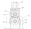
中継ローラ(300) は、図5、図6に詳細に示すように、中継セクション(B) のフレームの上面の前記リフタ(1) 側の端縁にて上下に並設され且夫々の表面にゴム等の摩擦係数の高い滑り止め層(S) を形成した上ロール(3a)及び下ロール(3b)と、下ロール(3b)を回転駆動するギヤードモータ(以下、単に駆動装置(31)という)と、上方の上ロール(3a)と前記下ロール(3b)に対して接離駆動させるエアーシリンダ(37)とからなる。
【0021】
前記下ロール(3b)は、前記フレームの上面の両側に設けた一対の軸受(34)(34)によって回転自在に軸支され、一方の軸受(34)から突出する軸部はトルクリミッタ(33)を介して前記駆動装置(31)の出力軸に連結されている。
他方の上ロール(3a)は、前記軸受(34)から上方に突出する一対のガイド軸によって昇降自在に支持された軸受体(35)(35)によってその両端が軸支され、前記ガイド軸の上端間をつなぐように、下ロール(3b)の上方に架設した架橋板(36)の上面に取付けたエアシリンダ(37)(37)の出力軸が前記軸受体(35)(35)に各別に連結されている。尚、前記エアシリンダ(37)(37)は同期して動作し、この動作によって上ロール(3a)が昇降駆動されて下ロール(3b)に対して接離する。(図4、図5参照)
下ロール(3b)は、ワーク(W) が投入されると、駆動装置(31)により回転駆動されて前記ワーク(W) は中継セクション(B) に投入される。
【0022】
[中継セクション(B) 及び打抜きセクション(C) について]
中継セクション(B) は、図2〜図4に示すように、これのフレームの一側に設けられる積層位置(A) と、前記のフレームの他側に設けられる打抜きセクション(C) との間に介在される。
打抜きセクション(C) は、その両端に設けられ且一対のローラ(R1)(R2)からなる間欠移送装置(4a)(4b)間に、打ち抜き機構を装備させた構成である。そして、一方の入口側の間欠移送装置(4a)と既述の中継ローラ(300) との間隔が一枚のワーク(W) の送り方向の長さよりも長く設定されている。
【0023】
前記間欠移送装置(4a)(4b)は共に、上記中継ローラ(300) と同じ構成であり、ワーク(W) 投入動作に合わせて上下のローラ(R1)(R2)(中継ローラ(300) の上ロール(3a)及び下ロール(3b)に相当する)が接離可能に構成れ、且、回転駆動される構成である。
この中継セクション(B) には、中継ローラ(300) によって送り込まれたワーク(W) を支持すると共に打抜きセクション(C) にワーク(W) を押出すための押出し装置(5) が設けられている。この押出し装置として、プーリ(52)(52)間に張設された押出しベルト(51)を採用する。前記押出しベルト(51)の上方には、バネ(53)の付勢力によって前記押出しベルト(51)の往路側に加圧される押圧ローラ(R3)が配備されている。そして、前記プーリ(52)(52)が所定のタイミングで作動し、この作動量に応じてワーク(W) が移送され、上下のローラ(R1)(R2)間に押し出される構成である。
【0024】
特に、この実施例の前記間欠移送装置(4a)のローラ(R1)(R2)は、他の間欠移送装置(4b)及び中継ローラ(300) とはことなり、常時所定の圧力で対接する構成であり、前記接触圧力は、上記押出しベルト(51)によって押出されたワーク(W) が、上方のローラ(R1)を押し上げて通過でき、しかも、ローラ(R1)(R2)で挟み付けたワーク(W) を下方のローラ(R2)の駆動によって前記ワーク(W) を間欠移送できる程度に設定されている。
又、下方のローラ(R2)にはストッパ(8) が設けられている。このストッパ(8)ハ 、図4のように、前記ローラ(R2)の両端外側に設けられ且前記ローラと同軸の回動支点を有する一対の腕(80)(80)の先端間を連結するように設けた湾曲板(81)であり、この湾曲板(81)は前記ローラ(R2)の表面に沿って湾曲する円弧状断面に構成され、この湾曲板(81)の上辺中央から突出させた舌辺部(82)がワーク(W) と当接する構成である。
【0025】
一方の腕(80)の入力端にはエアーシリンダ(83)の出力軸が連結され、このエアーシリンダ(83)の作動によって、前記湾曲板(81)の舌辺部(82)がローラ(R1)(R2)の境界部の下手側近傍に突出した状態と、前記舌辺部(82)がローラ(R2)の下部に降下揺動した揺動した状態とにセットされる。
このストッパ(8) の動作、及び、押出し装置(5) の動作は、制御装置によって次のように制御される構成となっている。
【0026】
先行するワーク(W) が間欠移送装置(4a)から外れた状態にあって、中継セクション(B) にワーク(W) が投入されると、図8のように、ストッパ(8) の舌片部(82)がローラ(R1)(R2)の接点部の下手側近傍に突出した状態にセットされる。その後、プーリ(52)(52)が駆動されて、図9のように、この押出しベルト(51)と押圧ローラ(R3)による推力によって前記ワーク(W) は対接状態にあるローラ(R1)(R2)を押し広げて前記ストッパ(8) に押しつけられる。
【0027】
そして、この後の頭出し制御により次の動作が実行される。
頭出し信号が入力されると、エアーシリンダ(83)の作動により、ストッパ(8) が下方に回動されて、駆動装置(31)の作動によりローラ(R2)が設定角度だけ回動されて、図7のように、ワーク(W) が前記ストッパ(8) から下手側に突出した状態にセットされる。つまり、既述の頭出し動作が実行される。
【0028】
ワーク(W) が中継セクションに投入される度に、押出しベルト(51)及び間欠移送装置(4a)による上記一連の制御動作が実行される。
打抜きセクション(C) は、公知の構成であり、間欠移送装置(4a)からワーク(W) が送り込まれると所定のタイミングで間欠移送装置(4b)との間に設けられた打ち抜き機構が作動してワーク(W) から一定形状の製品を打ち抜く。この実施例では、一枚のワーク(W) には、製品図柄が一定のピッチで行列状に印刷されており、打抜き機構にはワーク(W) の移送方向に対して横方向の印刷部(PT)数の打抜き型部が設けられ、一度に一行分が打抜かれる。また、ワーク(W) の移送方向の前方半分が打抜くまでは前記間欠移送装置(4a)によってワーク(W) が間欠移送され、この後、ワーク(W) の移送方向の後半部の打抜きでは、間欠移送装置(4b)によってワーク(W) が間欠移送され、打抜きが完了するとスクラップ部が前記間欠移送装置(4b)のローラ(R1)(R2)の回転によって打抜きセクション(C) から排出される。
【0029】
前記間欠移送装置(4b)の上方のローラ(R1)は、エアーシリンダ(37)によって下方のローラ(R1)に対して接離されるものであり、ワーク(W) についての打抜きが進行してワーク(W) (スクラップ)の先端がこの間欠移送装置(4b)に達する時点では、上方のローラが持ち上げられており、前記先端部が一定ストロークローラ(R1)(R2)間に侵入するとエアーシリンダ(37)によって上方のローラ(R1)が下方に押し下げられ、駆動装置(31)の駆動によって前記ワーク(W) の移送が開始されるようになっている。
【0030】
[移送モードについて]
なお、この実施例では、図10の(イ)〜(ハ)に示すように、先行するワーク(W) と後続のワーク(W) とがごく僅かの間隔(D) で連続する態様に上記間欠移送装置(4a)によって頭出しされた後、2つのワーク(W) が共に間欠移送されて製品が打ち抜かれる構成となっている。
【0031】
したがって、1サイクルのワーク(W) の移送ピッチの組み合わせ(以下、移送モードという)は、ワーク(W) に配列される製品を連続的に打抜くときの中間移送ピッチ(P1)と、先行するワーク(W) の後端の製品が打ち抜かれてから後続のワーク(W) の先頭の製品が打抜かれるまでの1つの継ぎ目移送ピッチ(P2)との組み合わせとなる。
【0032】
各ワーク(W) から全ての製品を打抜く為の打抜き回数(N) に対して、後続のワーク(W) が間欠移送装置(4a)から頭出しされた図10の(イ)の状態での打抜き回数を「0」とし、これから、先行するワーク(W) からの製品の打抜きが終了するまでの打抜き回数を(M) とすれば、前記ワーク(W) は、打抜き回数(M) までは中間移送ピッチ(P1)で間欠移送されて、図10の(ロ)の状態となり、その後継ぎ目移送ピッチ(P2)の移送が行われて図10の(ハ)の状態となり、この後は中間移送ピッチ(P1)で(N−M−1)回の間欠移送が行われて、図10の(イ)の状態に復帰する。
【0033】
尚、前記打ち抜き動作回数はカウンタ(6)(図示せず)によって計数される。また、上記移送ピッチの精度を高めるため、ローラ(R1)を駆動するための回転駆動装置(31)としては、サーボモータを採用している。上記1サイクルの移送モードを構成する移送ピッチのそれぞれに対応する駆動信号が前記サーボモータに入力される。
【0034】
この実施例では、カウンタ(6) の計数値が上記「N」になる度に、間欠移送装置(4a)側では頭出し動作が実行される、つまり、前記カウンタ(6) の計数値と上記設定値「N」とを比較する比較手段(請求項3の既述の第2検知手段に相当する)からの出力により、上記サーボモータが設定角度だけ回転駆動されて、その時点までストッパ(8) に押しつけられていたワーク(W) が一定寸法頭出しされて、図10の(イ)の状態となる。
【0035】
したがって、この実施例の上記サーボモータの制御は、カウンタ(6) の計数値が設定値(N) になる毎に、「一定寸法の頭出し」→「M階の中間移送ピッチ(P1)での送り」→「1回の継ぎ目移送ピッチ(P2)での送り」→「(N−M−1)回の中間移送ピッチ(P1)での送り」からなる一連の間欠移送動作が打抜き動作と同期するようにくり返し実行されるようになっている。
【0036】
また、先行するワーク(W) の後端が間欠移送装置(4a)から外れるまでの打抜き回数を「m」としてあり、カウンタ(6) の計数値が前記「m」に達したことを検知する比較手段を請求項3における第1検知手段としてあり、この第1検知手段からの出力により、ストッパ(8) を図7のように上方に回動させると共にプーリ(52)を駆動させて図9のようにワーク(W) をストッパ(8) に押しつけた状態にする構成としてある。
【0037】
[各部の動作について]
上記実施例の装置の場合、各部はマイクロコンピュータによって制御される。打抜き動作の実際を、図11に示すフローチャートに従って説明する。
始動時には中継セクション(B) 及び打抜きセクション(C) にはワーク(W) がないことから、間欠移送装置(4a)(4b)による上記移送モードの実行開始時期と打ち抜き機構の始動時期を設定するために、図7のように、中継セクション(B) にはワーク(W) を収容して、打抜きセクション(C) に一定寸法だけワーク(W) を頭出しした状態にセットする。(ステップST1)
これで初期設定が終了する。なお、このとき、吸盤(21)にはワーク(W) が同図のようには吸着されていない。
【0038】
この状態で、カウンタ(6) を作動させて、打抜き機構と間欠移送装置(4a)(4b)を同期的に作動させる。(ステップST2)
この初期設定の段階では、打抜き機構部にはワーク(W) が存在しない(図10−(イ)において、先行するワーク(W) がない状態)から、空打ち状態となり、所定回数の打抜きが実行されてワーク(W) の先端部が打抜き機構部に達した時点から実際の打抜き加工が実行される。
【0039】
この動作中にリフタ(1) に積層されているワーク(W) 群に対して次の吸着動作が実行される。
前記ワーク(W) 群に対して給紙方向における前方端近傍には、初期位置にある吸着装置(2a)の吸盤(21)は最上層のワーク(W) から離れている。そして、この後、吸着信号入力によって吸引装置(211) が「オン」となる( ステップST3)と共にエアーシリンダ(26)が正駆動して最上層のワーク(W) を吸着する。この後、エアーシリンダ(26)は一定の待機時間(0.1秒程度)を置いた後逆駆動されて吸盤(21)が上方の初期位置に復帰する。つまり、エアーシリンダ(26)の上記往復駆動によりワーク(W) が吸着保持される。(ステップ:ST4)
次いで、カウンタ(6) の計数値により、又は、ワーク(W) の後端の位置検知により、間欠移送装置(4a)からワーク(W) の後端が前方に外れたことが検知されると、(ステップST5 )、エアーシリンダ(27)が一定時間正駆動して予め設定された距離だけ取付け板(24)が中継ローラ(300) 側に駆動される。(ステップST6)
この実施例では、カウンタ(6) の計数値が「m」になったことを第1検知手段によって検知して上記動作を実行させるようにしてある。
【0040】
これにより、図7のように、前記吸盤(21)に吸着保持されたワーク(W) の先端が中継ローラ(300) の上ロール(3a)と下ロール(3b)との間に投入される。
なお、このとき、エアーシリンダ(37)が初期状態にあって上ローラ(3a)は下ローラ(3b)から上方に離されている。
この後、前記エアーシリンダ(37)が正駆動して、同図の破線で示すように、上ローラ(3a)が下ローラ(3b)に対接されて、吸引装置(211) がオフとなり(ステップST7)、駆動装置(31)により下ロール(3a)が一定角度(ワーク(W) を中継セクション(B) に投入するに必要な回転角度)回転駆動されて(ステップST8)、図8のように、ワーク(W) の全体が中継セクション(B) 内に完全送り込まれることとなる。この後、エアーシリンダ(27)が逆駆動されて初期位置に復帰する。(ステップST9)
次いで、エアーシリンダ(37)が逆駆動することにより上ローラ(3a)が持ち上げられて(ステップST10)、駆動装置(31)により移送ベルト(51)が一定距離正駆動される。(ステップST11)
このとき、ワーク(W) が間欠移送装置(4a)から外れているから、第1検知手段の出力によりエアーシリンダ(83)が作動しストッパ(8) が持ち上げられて、移送ベルト(51)が駆動される。この移送ベルト(51)と押圧ローラ(R3)とによる推力により、前記ワーク(W) は、対接状態にあるローラ(R1)(R2)を押し広げながら通過して、図9のように、前記ワーク(W) の先端が前記ストッパ(8) に押しつけられる。
【0041】
この後、先行するワーク(W) についての打抜き回数が設定回数(N) に達するとこれがステップST12(第2検知手段)によって判定されて、カウンタ(6) がリセットされると共に、移送装置(4a)の下方のロール(R2)を駆動する駆動装置(31)が設定角度回動されて、一定寸法頭出しされる。(ステップST13)
以後は、打ち抜き動作の間に、積層位置(A) では吸着装置(2a)の吸盤(21)が新たなワーク(W) を吸着保持した状態に待機され、先行するワーク(W) が間欠移送装置(4a)からはずれたことを検知する度に積層位置(A) から中継セクション(B) に新たなワーク(W) が給紙され、押出し装置(5) としての押出しベルト(51)の動作により、頭出し動作を待機した状態にセットされる。その後、カウンタ(6) の計数値が設定値(N) に達する度に間欠移送装置(4a)により後続のワーク(W) の頭出し動作が実行され、打抜きセクション(C) での打ち抜き動作を停止することなく積層されたワーク(W) 群が順次連続的に打ち抜かれることとなる。
【0042】
[その他]
この実施例では、本発明の装置を打ち抜き装置に於ける積層位置(A) から打抜きセクション(C) にワーク(W) を順次供給する場合に実施したが、他の加工装置に利用できることは言うまでもない。
また、上記実施例では、中継ローラ(300) と吸着移送装置(2) との組み合わせによって積層位置(A) のワーク(W) を順次中継セクション(B) に投入するようにしたが、吸着移送装置(2) によって積層位置(A) から直接中継セクション(B) にワーク(W) を投入するようにしてもよい。
【0043】
さらには、上記実施例では、押出し装置(5) として、中継セクション(B) のほぼ全域に張設した押出しベルト(51)の上手側のプーリ(52)を独立的に設けているが、図12のように、下ロール(3b)を前記プーリ(52)としてもよく、押圧ローラ(R3)に変えてワーク(W) を押出すための爪(59)を具備する構成とし、上ローラ(3a)の前記爪(59)の通過部を溝部としてもよい。又、前記爪(59)を具備する押出しベルト(51)を中継セクション(B) の上手側に部分的に設けても良い。また、ベルト装置に代えて、往復直線駆動装置を押出し装置(5) としても良い。 間欠移送装置(4a)からワーク(W) の後端が前方に外れたことを検知する方法として、上記実施例では、カウンタ(6) の計数値が所定の値「m」に達したかにより判断する方法を採用したが、ワーク(W) の後端の位置を検知する検知手段を間欠移送装置(4a)の近傍下手側に設けて、前記検知手段からの出力により、ワーク(W) の後端が間欠移送装置(4a)から前方に外れたことが検知するようにしてもよい。
【0044】
以上に詳記した何れの実施例でも中継セクション(B) から打抜きセクション(C) にワーク(W) を投入する際の頭出し装置に本発明を実施したが、中継セクションを設けることなく、吸盤(21)に吸着保持されたワーク(W) をそのまま間欠移送装置(4a)のローラ(R1)(R1)の接触点に押しつけるようにしてもよい。
【図面の簡単な説明】
【図1】従来例の説明図
【図2】本発明実施例の全体の説明図
【図3】要部の拡大図
【図4】ストッパ(8) の斜視図
【図5】中継ローラ(300) の断面図
【図6】中継ローラ(300) の正面図
【図7】中継セクション(B) にワーク(W) を収容した状態の説明図
【図8】中継セクション(B) でのワーク押出し状態の説明図
【図9】頭出し状態の説明図
【図10】打抜きセクション(C) でのワーク(W) の間欠移送動作説明図。
【図11】給紙動作のフローチャート図
【図12】他の実施例の要部説明図
【符号の説明】
(W) ・・・ワーク
(2) ・・・吸着移送装置
(R1)(R2)・・・ローラ
(300) ・・・中継ローラ
(4a)(4b)・・・間欠移送装置
(5) ・・・押出し装置
(51)・・・押出しベルト[0001]
[Industrial application fields]
The present invention relates to an apparatus for supplying sheets to a processing section, and more particularly to an apparatus for continuously supplying sheets one by one to a processing section.
[0002]
[Prior art and problems]
This type of sheet supply apparatus is employed in a punching apparatus as shown in FIG. In this punching device, intermittent transfer devices (4a) and (4b) comprising a pair of rollers are provided on the inlet side and outlet side of the workpiece (W) in the punching section. Next, a lifter (1) that lifts a workpiece (W) such as a sheet or sheet in a stacked state at a predetermined timing adjacent to the entrance side, and a work (W) on the uppermost layer of the lifter (1) ) And a transfer device (2b) for transferring the workpiece (W) to the intermittent transfer device (4a) on the inlet side of the punching section. And a sheet feeding device comprising the device (2). Accordingly, the workpiece (W) thrown in by the suction transfer device (2) is intermittently fed into the punching section by the intermittent transfer device (4a) on the inlet side.
[0003]
In the punching section, the workpiece (W) charged therein is initially intermittently transferred to the punching mechanism portion at a predetermined timing by the intermittent transfer device (4a) on the inlet side, and thereafter the intermittent transfer device (4a) ( After passing through a state where both the front and rear sides in the transfer direction of the workpiece (W) are intermittently transferred synchronously by 4b), finally the workpiece (W) is intermittently transferred by the intermittent transfer device (4b) on the outlet side.
[0004]
Then, when the processing for the preceding workpiece (W) is completed, a new workpiece (W) held by the suction device (2a) is put into the intermittent transfer device (4a) on the inlet side, and the above-described series of punching is performed. The action is executed.
However, in this case, even if the speed of the operation of the punching mechanism itself can be increased, it is not possible to shorten the time required for punching the entire workpieces (W) and (W) that are continuous back and forth. This is because, after the punching of the preceding workpiece (W) is completed, the waiting time until the punching of the subsequent workpiece (W) is started becomes longer than necessary.
[0005]
Therefore, the workpiece (W) sucked by the suction device (2a) is introduced into the intermittent transfer device (4a) on the inlet side when machining of the workpiece (W) put into the punching section has progressed to some extent, and this intermittent A method is conceivable in which the punching process is continued after the new workpiece (W) is cued to a certain size by the transfer device (4a). In this case, in the punching section, the punching operation is executed in a manner without the above-described waiting time.
[0006]
However, in this case, when the transfer amount of the intermittent transfer device (4a) for cueing is set constant, a new work (W) sucked and held by the suction device (2a) and the intermittent transfer device ( If there is a variation in the distance to 4a), this variation will cause a variation in the cue dimension as it is, and accurate punching to each workpiece (W) will not be possible.
The present invention has been made in view of the above points, and when a sheet-like workpiece (W) is cueed to a certain size by an intermittent transfer device (4a) provided on the inlet side of a machining section that performs a punching operation or the like. Therefore, it is an object of the present invention to improve the cue dimension accuracy so that the machining accuracy of continuous machining on the workpiece (W) can be increased.
[0007]
[Invention of Claim 1]
[0008]
[Technical means]
The technical means of the present invention for solving the above-mentioned problem is that a sheet-like workpiece (W) is fixed to the machining section by an intermittent transfer device (4a) provided on the inlet side of the machining section by inputting a cueing signal. In the sheet feeding device in which the dimension is cueed and then the workpiece (W) is intermittently transferred in accordance with the machining operation.
The intermittent transfer device (4a) has a pair of upper and lower rollers (R 1 ) (R 2 ) To clamp the workpiece (W) and intermittently transfer the workpiece (W). 1 ) (R 2 ) And the transfer operation is stopped when it is off.
Provided with a workpiece standby unit for waiting for a new unprocessed workpiece (W) continuously on the upper side of the intermittent transfer device (4a),
The intermittent transfer device (4a) is provided with a stopper (8) that appears and disappears in the transfer path of the workpiece (W) in the vicinity of the lower side,
The workpiece (W) waiting in the workpiece standby section is pushed out to the lower side, and the tip of the workpiece (W) is pushed to the roller (R 1 ) (R 2 ) And an extrusion device (5) for pressing against the stopper (8).
Roller (R) of the intermittent transfer device (4a) 1 ) (R 2 Drive device (31) for driving the roller (R 1 ) (R 2 ) Is rotated by an angle corresponding to the input signal value,
After the trailing end of the preceding work (W) has been disengaged from the intermittent transfer device (4a), the stopper (8) protrudes into the work transfer path and the subsequent work (W) accommodated in the work standby section is pushed out. A workpiece extrusion control means which is extruded by (5) and presses the tip of the subsequent workpiece (W) against the stopper (8);
The stopper (8) is retracted from the workpiece transfer path after the pushing operation for the subsequent workpiece (W) is completed, and the driving device (31) is rotated by an angle corresponding to the cueing dimension by inputting a cueing signal. And a cueing control means.
[0009]
[Action]
The technical means operates as follows.
When machining in the machining section for the preceding workpiece (W) progresses and the rear end of the workpiece (W) is disengaged from the intermittent transfer device (4a), the workpiece waited in the workpiece standby section during the machining. (W) is pushed to the lower side and the tip of the roller (R) of the intermittent transfer device (4a) is pushed. 1 ) (R 2 ) And press against the stopper (8) protruding into the transfer path.
[0010]
Thereafter, the cueing control means retracts the stopper (8) from the transfer path of the workpiece (W), and the operation of the drive device (31) of the intermittent transfer device (4a) is controlled so that the roller (R 1 ) (R 2 ), A cueing operation with a fixed dimension is executed.
Thus, when the workpiece (W) is cueed to the machining section, the tip of the workpiece (W) is pressed against the stopper (8) and the roller (R 1 ) (R 2 Cueing is performed only for the dimension set by the rotation angle.
[0011]
【effect】
The cueing dimension is the roller (R 1 ) (R 2 ) Is exactly the same as the rotation angle of the roller (R 1 ) (R 2 ) Is rotated by a certain angle, the cueing position becomes accurate, and the accuracy of the machining start position of the workpiece (W) newly input to the machining section is improved.
[0012]
The tip of the subsequent workpiece (W) has a pair of rollers (R 1 ) (R 2 ) Is pressed against the stopper (8) provided at the position passing through the boundary of the roller (R) 1 ) (R 2 Cueing operation by forward rotation) is smooth and reliable, and cueing operation failure can be prevented.
When cueing, the roller (R 1 ) (R 2 ) Should be in contact with the workpiece (W) to the extent that the workpiece (W) is allowed to pass or the interval to allow the passage is sufficient. it can.
[0013]
In the cueing device that detects the tip of the workpiece (W) with a sensor, it is necessary to set the transfer speed during cueing to be slow in order to prevent overrun of the workpiece (W). Since this is not necessary, the cueing operation can be accelerated at this point.
[Other inventions]
As defined in
[0014]
As defined in
An intermittent transfer device (4b) is provided on the outlet side of the punching section, and this is interlocked with the intermittent transfer device (4a) so that the workpiece (W) headed in the punching section is matched with the punching operation. And a workpiece loading / unloading device configured to discharge from the processing section after completion of punching,
In the cueing state, the cue dimension is set so that the succeeding work (W) is continuous with the preceding work (W) with a predetermined gap,
The workpiece loading / unloading device is a punching operation in which a cueing operation by an intermittent transfer device (4a) and an intermittent transfer operation of the workpiece (W) for punching a product from the workpiece (W) are performed at regular time intervals. `` Synchronized with operation '' means that each operation is executed in synchronization with the punching operation that is continuously executed at regular time intervals, so the workpiece (W) is brought into the positioning state by the stopper (8). After the extrusion, the workpieces (W) (W) to be cued can be continuously punched without interrupting the punching operation and without changing the punching operation interval.
[0015]
As defined in
[0016]
【Example】
Next, the embodiment of the present invention described above will be described in detail with reference to the drawings.
The embodiment shown in FIGS. 2 to 11 is an embodiment in which the present invention is applied to a punching device such as a prepaid card or a cash card, and is supported in a laminated state by a lifter (1) as shown in FIGS. The workpieces (W) (W) made of the synthetic resin sheet thus transferred are intermittently transferred from the stacking position (A) to the punching section (C) via the relay section (B), and this punching section (C) A predetermined printing section is punched out from the workpiece (W) to obtain a prepaid card or a cash card.
[0017]
[About lifter (1) and adsorption transfer device (2)]
The lifter (1) has a structure in which a work (W) formed on a rectangular sheet is stacked on a lifting platform (11), and the lifting platform (11) is lifted intermittently. Is supported by the side wall of the frame of the relay section (B).
When the work (W) (W) within a certain range from the uppermost layer is thrown into the relay section (B), the elevator (11) is lifted by a certain distance.
[0018]
The adsorption transfer device (2) is composed of an adsorption device and a transfer device for transferring the adsorption device.
As shown in FIGS. 2 and 3, the suction device includes a swing arm (25) swingably supported by a mounting plate (24), and a suction cup provided at the tip of the swing arm (25). 21) and an air cylinder (26) for swinging the swing arm (25) at a predetermined timing.
A flexible suction circuit extending from a suction device (211) is connected to the suction cup (21), and this suction device (211) is activated when the workpiece (W) is sucked and held.
[0019]
The transfer and transfer device includes an air cylinder in which the guide shaft (23) (23) and an output shaft attached to the support bar (22) and penetrating the support bar (22) are connected to the mounting plate (24). The swing arm (25) attached to the mounting plate (24) by the operation of the air cylinder (27) is connected to the relay roller (300) provided on the entrance side of the relay section (B). It is the composition which advances and retracts.
[0020]
[About Relay Roller (300)]
As shown in detail in FIGS. 5 and 6, the relay roller (300) is juxtaposed vertically at the edge of the upper surface of the frame of the relay section (B) on the lifter (1) side, and on each surface. An upper roll (3a) and a lower roll (3b) on which a non-slip layer (S) having a high friction coefficient such as rubber is formed, and a geared motor (hereinafter simply referred to as a drive device (31)) that rotationally drives the lower roll (3b) ) And an air cylinder (37) driven to contact and separate from the upper roll (3a) and the lower roll (3b).
[0021]
The lower roll (3b) is rotatably supported by a pair of bearings (34) (34) provided on both sides of the upper surface of the frame, and a shaft portion protruding from one bearing (34) has a torque limiter (33 ) To the output shaft of the drive device (31).
The other upper roll (3a) is pivotally supported at both ends by a bearing body (35) (35) supported by a pair of guide shafts protruding upward from the bearing (34), The output shafts of the air cylinders (37) and (37) attached to the upper surface of the bridge plate (36) installed above the lower roll (3b) are connected to the bearing bodies (35) and (35) so as to connect the upper ends. It is connected separately. The air cylinders (37) and (37) operate in synchronism with each other, and the upper roll (3a) is driven up and down by this operation to contact and separate from the lower roll (3b). (See Figs. 4 and 5)
When the work (W) is thrown into the lower roll (3b), the lower roll (3b) is rotationally driven by the driving device (31), and the work (W) is thrown into the relay section (B).
[0022]
[About relay section (B) and punching section (C)]
As shown in FIGS. 2 to 4, the relay section (B) is located between the stacking position (A) provided on one side of the frame and the punching section (C) provided on the other side of the frame. Intervened in.
The punching section (C) is provided at both ends and a pair of rollers (R 1 ) (R 2 ) Between the intermittent transfer devices (4a) and (4b). The interval between the intermittent transfer device (4a) on one inlet side and the relay roller (300) described above is set to be longer than the length in the feed direction of one workpiece (W).
[0023]
Both the intermittent transfer devices (4a) and (4b) have the same configuration as the relay roller (300), and the upper and lower rollers (R) 1 ) (R 2 ) (Corresponding to the upper roll (3a) and the lower roll (3b) of the relay roller (300)) can be brought into contact with and separated from each other and is driven to rotate.
The relay section (B) is provided with an extruding device (5) for supporting the work (W) fed by the relay roller (300) and for extruding the work (W) to the punching section (C). Yes. As this extrusion device, an extrusion belt (51) stretched between pulleys (52) and (52) is employed. Above the extrusion belt (51), a pressing roller (R) pressed against the forward path side of the extrusion belt (51) by the biasing force of a spring (53). Three ) Is deployed. The pulleys (52) and (52) are operated at a predetermined timing, and the workpiece (W) is transferred according to the operation amount, and the upper and lower rollers (R 1 ) (R 2 ).
[0024]
In particular, the roller (R) of the intermittent transfer device (4a) of this embodiment. 1 ) (R 2 ) Is different from the other intermittent transfer device (4b) and the relay roller (300), and is always in contact with a predetermined pressure, the contact pressure is a work piece extruded by the extrusion belt (51) ( W) is the upper roller (R 1 ) Can be pushed up, and the roller (R 1 ) (R 2 ) Between the workpiece (W) and the lower roller (R 2 ) Is set to such an extent that the workpiece (W) can be intermittently transferred.
The lower roller (R 2 ) Is provided with a stopper (8). This stopper (8) has the roller (R) as shown in FIG. 2 ) And a curved plate (81) provided so as to connect between the tips of a pair of arms (80) and (80) having a rotation fulcrum coaxial with the roller. ) Is the roller (R 2 ) And a tongue-side portion (82) protruding from the center of the upper side of the curved plate (81) is in contact with the workpiece (W).
[0025]
The output shaft of the air cylinder (83) is connected to the input end of one arm (80), and the operation of the air cylinder (83) causes the tongue (82) of the curved plate (81) to move to the roller (R 1 ) (R 2 ) Projecting in the vicinity of the lower side of the boundary portion, and the tongue side portion (82) is a roller (R 2 ) Is set at the lower part of).
The operation of the stopper (8) and the operation of the extrusion device (5) are controlled by the control device as follows.
[0026]
When the preceding workpiece (W) is detached from the intermittent transfer device (4a) and the workpiece (W) is inserted into the relay section (B), the tongue of the stopper (8) as shown in FIG. Part (82) is roller (R 1 ) (R 2 ) Is set in a state protruding near the lower side of the contact portion. Thereafter, the pulleys (52) and (52) are driven, and the push belt (51) and the pressure roller (R) are driven as shown in FIG. Three ), The workpiece (W) is in contact with the roller (R 1 ) (R 2 ) Is spread and pressed against the stopper (8).
[0027]
Then, the following operation is executed by the subsequent cue control.
When the cueing signal is input, the stopper (8) is rotated downward by the operation of the air cylinder (83), and the roller (R) is operated by the operation of the drive device (31). 2 ) Is rotated by a set angle, and the workpiece (W) is set to protrude from the stopper (8) to the lower side as shown in FIG. That is, the above-described cueing operation is executed.
[0028]
Each time the work (W) is put into the relay section, the above-described series of control operations by the extrusion belt (51) and the intermittent transfer device (4a) are executed.
The punching section (C) has a known configuration, and when the workpiece (W) is fed from the intermittent transfer device (4a), the punching mechanism provided between the intermittent transfer device (4b) is activated at a predetermined timing. Punch a product of a certain shape from the workpiece (W). In this embodiment, product symbols are printed in a matrix at a constant pitch on a single workpiece (W), and the punching mechanism has a printing section (in a direction transverse to the transfer direction of the workpiece (W) ( PT) number of punching dies are provided, and one line is punched at a time. Also, the workpiece (W) is intermittently transferred by the intermittent transfer device (4a) until the front half of the workpiece (W) in the transfer direction is punched. The workpiece (W) is intermittently transferred by the intermittent transfer device (4b), and when the punching is completed, the scrap portion is transferred to the roller (R) of the intermittent transfer device (4b). 1 ) (R 2 ) Is discharged from the punching section (C).
[0029]
Roller (R) above the intermittent transfer device (4b) 1 ) The lower roller (R 1 ), When the punching of the workpiece (W) proceeds and the tip of the workpiece (W) (scrap) reaches the intermittent transfer device (4b), the upper roller is lifted. The tip is a constant stroke roller (R 1 ) (R 2 ), The upper roller (R 1 ) Is pushed downward, and the transfer of the workpiece (W) is started by the drive of the drive device (31).
[0030]
[About transfer mode]
In this embodiment, as shown in FIGS. 10 (a) to (c), the preceding work (W) and the succeeding work (W) are continuous with a very small distance (D). After cueing by the intermittent transfer device (4a), the two workpieces (W) are intermittently transferred together and the product is punched out.
[0031]
Therefore, the combination of the transfer pitches of one cycle of workpiece (W) (hereinafter referred to as transfer mode) is the intermediate transfer pitch (P) when the products arranged on workpiece (W) are continuously punched. 1 ) And one seam transfer pitch (P) from when the rear end product of the preceding workpiece (W) is punched to when the first product of the subsequent workpiece (W) is punched. 2 ).
[0032]
In the state shown in FIG. 10 (a), the succeeding workpiece (W) is cued from the intermittent transfer device (4a) with respect to the number of punches (N) for punching all products from each workpiece (W). If the number of punches is set to “0” and the number of punches until the end of the punching of the product from the preceding workpiece (W) is assumed to be (M), the workpiece (W) will reach the number of punches (M). Is the intermediate transfer pitch (P 1 ) Is intermittently transferred to the state of (b) in FIG. 2 ) Is transferred to the state of (c) in FIG. 10, and thereafter, the intermediate transfer pitch (P 1 ), (N−M−1) times of intermittent transfer is performed, and the state of FIG.
[0033]
The number of punching operations is counted by a counter (6) (not shown). In order to increase the accuracy of the transfer pitch, a roller (R 1 As the rotation drive device (31) for driving the servomotor, a servo motor is employed. Drive signals corresponding to the transfer pitches constituting the one-cycle transfer mode are input to the servo motor.
[0034]
In this embodiment, every time the count value of the counter (6) becomes “N”, the cueing operation is executed on the intermittent transfer device (4a) side, that is, the count value of the counter (6) The servo motor is rotated by a set angle by an output from a comparison means (corresponding to the second detection means described above in claim 3) for comparing with a set value “N”, and a stopper (8 The workpiece (W) pressed against () is cued to a certain dimension, and the state shown in FIG.
[0035]
Therefore, the control of the servo motor of this embodiment is performed every time the count value of the counter (6) reaches the set value (N). 1 ) ”→” One-time seam transfer pitch (P 2 ) ”→” (N−M−1) intermediate transfer pitch (P 1 A series of intermittent transfer operations consisting of “feeding at“) ”are repeatedly executed so as to synchronize with the punching operation.
[0036]
The number of punches until the trailing edge of the preceding work (W) is removed from the intermittent transfer device (4a) is “m”, and it is detected that the count value of the counter (6) has reached the “m”. The comparison means is the first detection means in
[0037]
[Operation of each part]
In the case of the apparatus of the above embodiment, each unit is controlled by a microcomputer. The actual punching operation will be described with reference to the flowchart shown in FIG.
Since there is no work (W) in the relay section (B) and the punching section (C) at the start, the execution start timing of the above transfer mode and the punching mechanism start timing by the intermittent transfer devices (4a) (4b) are set. Therefore, as shown in FIG. 7, the work section (B) is accommodated in the relay section (B), and the work section (W) is set in a state where the work (W) is cueed to the punching section (C). (Step ST1)
This completes the initial setting. At this time, the work (W) is not attracted to the suction cup (21) as shown in FIG.
[0038]
In this state, the counter (6) is operated, and the punching mechanism and the intermittent transfer devices (4a) (4b) are operated synchronously. (Step ST2)
At the initial setting stage, there is no workpiece (W) in the punching mechanism (the state in which there is no preceding workpiece (W) in FIG. 10- (b)), and the blanking state is reached, and a predetermined number of punches are performed. The actual punching process is executed from the point in time when the tip of the workpiece (W) reaches the punching mechanism.
[0039]
During this operation, the next suction operation is performed on the workpiece (W) group stacked on the lifter (1).
In the vicinity of the front end in the sheet feeding direction with respect to the workpiece (W) group, the suction cup (21) of the suction device (2a) in the initial position is separated from the uppermost workpiece (W). Thereafter, the suction device (211) is turned “ON” by the suction signal input (step ST3) and the air cylinder (26) is driven forward to suck the uppermost workpiece (W). Thereafter, the air cylinder (26) is driven in reverse after a certain waiting time (about 0.1 second), and the suction cup (21) returns to the upper initial position. That is, the workpiece (W) is sucked and held by the reciprocating drive of the air cylinder (26). (Step: ST4)
Next, when it is detected from the intermittent transfer device (4a) that the rear end of the workpiece (W) has moved forward by the count value of the counter (6) or by detecting the position of the rear end of the workpiece (W). (Step ST5), the air cylinder (27) is positively driven for a predetermined time, and the mounting plate (24) is driven to the relay roller (300) side by a preset distance. (Step ST6)
In this embodiment, the first detection means detects that the count value of the counter (6) has reached "m", and the above operation is executed.
[0040]
Accordingly, as shown in FIG. 7, the tip of the work (W) attracted and held by the suction cup (21) is put between the upper roll (3a) and the lower roll (3b) of the relay roller (300). .
At this time, the air cylinder (37) is in the initial state, and the upper roller (3a) is separated upward from the lower roller (3b).
Thereafter, the air cylinder (37) is driven forward, the upper roller (3a) is brought into contact with the lower roller (3b), and the suction device (211) is turned off as indicated by the broken line in FIG. In step ST7), the lower roll (3a) is driven to rotate by a fixed angle (rotation angle necessary to put the work (W) into the relay section (B)) by the drive device (31) (step ST8), and the process shown in FIG. Thus, the whole work (W) is completely fed into the relay section (B). Thereafter, the air cylinder (27) is reversely driven to return to the initial position. (Step ST9)
Next, the air cylinder (37) is reversely driven to lift the upper roller (3a) (step ST10), and the drive belt (51) is positively driven by a fixed distance by the drive device (31). (Step ST11)
At this time, since the workpiece (W) is detached from the intermittent transfer device (4a), the air cylinder (83) is actuated by the output of the first detecting means, the stopper (8) is lifted, and the transfer belt (51) is moved. Driven. This transfer belt (51) and pressure roller (R Three ), The workpiece (W) is brought into contact with the roller (R 1 ) (R 2 ) Is pushed and spread, and the tip of the workpiece (W) is pressed against the stopper (8) as shown in FIG.
[0041]
Thereafter, when the number of punches for the preceding workpiece (W) reaches the set number (N), this is determined by step ST12 (second detecting means), the counter (6) is reset, and the transfer device (4a ) Down roll (R 2 ) Is rotated by a set angle to find a fixed dimension. (Step ST13)
Thereafter, during the punching operation, at the stacking position (A), the suction cup (21) of the suction device (2a) stands by while holding a new work (W), and the preceding work (W) is intermittently transferred. New workpiece (W) is fed from the stacking position (A) to the relay section (B) every time it is detected that it is detached from the device (4a), and the operation of the extrusion belt (51) as the extrusion device (5) Thus, the head is set in a state waiting for the cueing operation. After that, every time the count value of the counter (6) reaches the set value (N), the intermittent transfer device (4a) performs the cueing operation of the subsequent workpiece (W) and performs the punching operation in the punching section (C). The stacked workpiece (W) groups are sequentially punched without stopping.
[0042]
[Others]
In this embodiment, the apparatus of the present invention is used when the workpiece (W) is sequentially supplied from the stacking position (A) in the punching apparatus to the punching section (C), but it goes without saying that it can be used for other processing apparatuses. Yes.
In the above embodiment, the workpiece (W) at the stacking position (A) is sequentially put into the relay section (B) by the combination of the relay roller (300) and the suction transfer device (2). The work (W) may be directly fed from the stacking position (A) to the relay section (B) by the device (2).
[0043]
Furthermore, in the above embodiment, as the extrusion device (5), the pulley (52) on the upper side of the extrusion belt (51) stretched over almost the entire area of the relay section (B) is provided independently. 12, the lower roll (3b) may be the pulley (52), and the pressure roller (R Three ), And a claw (59) for extruding the workpiece (W) may be provided, and the passage portion of the claw (59) of the upper roller (3a) may be a groove. Further, an extrusion belt (51) having the claw (59) may be partially provided on the upper side of the relay section (B). Further, instead of the belt device, a reciprocating linear drive device may be used as the extrusion device (5). As a method for detecting that the rear end of the workpiece (W) has moved forward from the intermittent transfer device (4a), in the above embodiment, the counter (6) count value depends on whether or not the predetermined value “m” has been reached. Although the determination method is adopted, a detection means for detecting the position of the rear end of the workpiece (W) is provided on the lower side near the intermittent transfer device (4a), and the output of the workpiece (W) is determined by the output from the detection means. It may be detected that the rear end has moved forward from the intermittent transfer device (4a).
[0044]
In any of the embodiments described in detail above, the present invention was applied to the cueing device when the workpiece (W) was put into the punching section (C) from the relay section (B). The workpiece (W) adsorbed and held by (21) is directly transferred to the rollers (R) of the intermittent transfer device (4a). 1 ) (R 1 ) May be pressed against the contact point.
[Brief description of the drawings]
FIG. 1 is an explanatory diagram of a conventional example
FIG. 2 is an overall explanatory diagram of an embodiment of the present invention.
FIG. 3 is an enlarged view of the main part.
FIG. 4 is a perspective view of the stopper (8).
Fig. 5 Cross section of relay roller (300)
[Fig. 6] Front view of relay roller (300)
FIG. 7 is an explanatory diagram showing a state in which a work (W) is accommodated in the relay section (B).
[Fig. 8] Explanatory drawing of workpiece pushing state in relay section (B)
FIG. 9 is an explanatory diagram of the cueing state.
FIG. 10 is an explanatory diagram of the intermittent transfer operation of the workpiece (W) in the punching section (C).
FIG. 11 is a flowchart of a paper feeding operation.
FIG. 12 is an explanatory diagram of the main part of another embodiment.
[Explanation of symbols]
(W) ・ ・ ・ Work
(2) ... Suction transfer device
(R 1 ) (R 2 )···roller
(300) ... Relay roller
(4a) (4b) ・ ・ ・ Intermittent transfer device
(5) ... Extruding equipment
(51) ... Extruded belt
Claims (5)
前記間欠移送装置(4a)は上下一対のローラ(R1)(R2)によってワーク(W) をクランプして間欠移送する構成とすると共に、前記ワーク(W) が前記ローラ(R1)(R2)から外れると移送動作を停止する構成とし、
前記間欠移送装置(4a)の上手側に連続させて未加工の新たなワーク(W) を待機させるためのワーク待機部を設けると共に、
前記間欠移送装置(4a)の下手側近傍にワーク(W) の移送経路に出没するストッパ(8) を設け、
前記ワーク待機部内に待機させたワーク(W) を下手側に押出してその先端を前記ローラ(R1)(R2)間を通過させて前記ストッパ(8) に押し当てるための押出し装置(5) を設け、
前記間欠移送装置(4a)のローラ(R1)(R2)を駆動する為の駆動装置(31)は、前記ローラ(R1)(R2)を入力信号値に応じた角度だけ回転駆動する構成とし、
先行するワーク(W) の後端が間欠移送装置(4a)から外れた後に前記ストッパ(8) をワーク移送経路に突出させて前記ワーク待機部に収容された後続のワーク(W) を押出し装置(5) により押出して前記後続のワーク(W) の先端を前記ストッパ(8) に押し付けるようにしたワーク押出し制御手段と、
後続のワーク(W) に対する前記押出し動作終了後に前記ストッパ(8) をワーク移送経路から退避させ、頭出し信号入力により前記駆動装置(31)を頭出し寸法に相当する角度回転させるようにした頭出し制御手段と、
を設けたシート類の供給装置。When the cueing signal is input, the intermittent transfer device (4a) provided on the inlet side of the machining section causes the sheet-like workpiece (W) to cue to the machining section with a certain dimension, and then the workpiece (W) is machined. In the sheet supply device adapted to be intermittently transferred in accordance with the
The intermittent transfer device (4a) is configured to clamp and transfer the workpiece (W) intermittently with a pair of upper and lower rollers (R 1 ) (R 2 ), and the workpiece (W) is connected to the rollers (R 1 ) ( R 2 )
Provided with a workpiece standby unit for waiting for a new unprocessed workpiece (W) continuously on the upper side of the intermittent transfer device (4a),
The intermittent transfer device (4a) is provided with a stopper (8) that appears and disappears in the transfer path of the workpiece (W) in the vicinity of the lower side,
An extruding device (5) for extruding the work (W) waited in the work waiting section to the lower side and passing the tip between the rollers (R 1 ) (R 2 ) and pressing it against the stopper (8) )
The drive device (31) for driving the rollers (R 1 ) and (R 2 ) of the intermittent transfer device (4a) rotates the rollers (R 1 ) and (R 2 ) by an angle corresponding to the input signal value. With a configuration to
After the trailing end of the preceding work (W) has been disengaged from the intermittent transfer device (4a), the stopper (8) protrudes into the work transfer path and the subsequent work (W) accommodated in the work standby section is pushed out. A workpiece extrusion control means which is extruded by (5) and presses the tip of the subsequent workpiece (W) against the stopper (8);
The stopper (8) is retracted from the workpiece transfer path after the pushing operation for the subsequent workpiece (W) is completed, and the driving device (31) is rotated at an angle corresponding to the cueing dimension by inputting a cueing signal. Dispensing control means;
Sheet supply device provided with
前記ワーク押出し動作後に先行するワーク(W) の加工が加工終了前の所定の段階に達したことを検知する第2検知手段を設け、この第2検知手段を上記頭出し信号とした請求項1又は請求項2に記載のシート類の供給装置。First detection means for detecting that the preceding work (W) has come off from the intermittent transfer device (4a) is provided, and the work push-out control means is provided with a push-out device (5) in response to the detection signal output of the first detection means. )
2. A second detecting means for detecting that the processing of the preceding workpiece (W) after the workpiece pushing operation has reached a predetermined stage before the end of processing is provided, and the second detecting means is used as the cueing signal. Or the supply apparatus of the sheets of Claim 2.
この打抜きセクションの出口側には前記間欠移送装置(4a)と同期的に又は独立して動作する間欠移送装置(4b)を設け、
これら間欠移送装置(4a)(4b)により、打抜きセクションに頭出しされたワーク(W) を前記打抜き動作に合わせて間欠移送させると共に、打抜き終了後にスクラップを前記打抜きセクションから排出させるようにしたワーク投入排出装置を構成し、
前記頭出し状態において後続のワーク(W) が先行するワーク(W) と所定の間隙を空けて連続するように頭出し寸法を設定し、
前記ワーク投入排出装置は、前記間欠移送装置(4a)による上記頭出し動作、前記ワーク投入排出装置によるワーク(W) の間欠移送動作及びスクラップ排出動作の夫々を、一定時間間隔で実行される打抜き動作に同期させた請求項1〜3の何れかに記載のシート類の供給装置。The processing section is a punching section in which products of the same shape are sequentially punched from the workpiece (W) and the punching operation is continuously executed at regular time intervals.
On the outlet side of this punching section, an intermittent transfer device (4b) that operates synchronously or independently with the intermittent transfer device (4a) is provided,
By these intermittent transfer devices (4a) and (4b), the workpiece (W) headed to the punching section is intermittently transferred in accordance with the punching operation, and the scrap is discharged from the punching section after the punching is completed. Configure the input / output device,
In the cueing state, the cue dimension is set so that the succeeding work (W) is continuous with the preceding work (W) with a predetermined gap,
The workpiece charging / discharging device is a punching operation in which the cueing operation by the intermittent transfer device (4a), the intermittent transfer operation of the workpiece (W) by the workpiece charging / discharging device, and the scrap discharging operation are performed at regular time intervals. The sheet supply apparatus according to claim 1, which is synchronized with an operation.
Priority Applications (1)
| Application Number | Priority Date | Filing Date | Title |
|---|---|---|---|
| JP14091995A JP3676428B2 (en) | 1995-06-07 | 1995-06-07 | Sheet supply device |
Applications Claiming Priority (1)
| Application Number | Priority Date | Filing Date | Title |
|---|---|---|---|
| JP14091995A JP3676428B2 (en) | 1995-06-07 | 1995-06-07 | Sheet supply device |
Publications (2)
| Publication Number | Publication Date |
|---|---|
| JPH08324840A JPH08324840A (en) | 1996-12-10 |
| JP3676428B2 true JP3676428B2 (en) | 2005-07-27 |
Family
ID=15279874
Family Applications (1)
| Application Number | Title | Priority Date | Filing Date |
|---|---|---|---|
| JP14091995A Expired - Fee Related JP3676428B2 (en) | 1995-06-07 | 1995-06-07 | Sheet supply device |
Country Status (1)
| Country | Link |
|---|---|
| JP (1) | JP3676428B2 (en) |
Family Cites Families (3)
| Publication number | Priority date | Publication date | Assignee | Title |
|---|---|---|---|---|
| JPS4618942Y1 (en) * | 1966-04-18 | 1971-07-01 | ||
| JPS4734184U (en) * | 1971-05-07 | 1972-12-16 | ||
| JP2910274B2 (en) * | 1991-03-06 | 1999-06-23 | 三菱マテリアル株式会社 | Intermittent sheet feeder for punching press of information storage card |
-
1995
- 1995-06-07 JP JP14091995A patent/JP3676428B2/en not_active Expired - Fee Related
Also Published As
| Publication number | Publication date |
|---|---|
| JPH08324840A (en) | 1996-12-10 |
Similar Documents
| Publication | Publication Date | Title |
|---|---|---|
| US9033646B2 (en) | Cardboard sheet batch division device, cardboard sheet counter ejector, and method for dividing cardboard sheet | |
| CN114890206B (en) | Test card die cutting production equipment and control method thereof | |
| US6363845B1 (en) | Method of transferring a sheet through a working apparatus | |
| JP3676428B2 (en) | Sheet supply device | |
| US5123807A (en) | System for stacking veneer sheets conveyed from two different directions | |
| JP3678460B2 (en) | Sheet supply method and apparatus | |
| US6016747A (en) | Printing press coupler accumulator | |
| US3605249A (en) | Registered joinder of sheet | |
| RU2727677C1 (en) | Device for transfer of veneer sheets with possibility of tight connection of sheets of veneer of non-standard size | |
| JP3621734B2 (en) | Sheet supply method and apparatus | |
| CN212551103U (en) | Plate shearing machine with width detection function | |
| JP3561545B2 (en) | Sheet supply method and sheet supply apparatus | |
| EP0333046A1 (en) | System for stacking veneer sheets conveyed from two different directions | |
| JPH07285693A (en) | Paper feeding method and paper feeding device | |
| CN221233281U (en) | Square sheet positioning gilding press | |
| JPH081248A (en) | Shaping method for sheet bar stock | |
| JPS62192219A (en) | Work feeding system for press | |
| JP3250202B2 (en) | Punching equipment | |
| JPH0638036Y2 (en) | Device for collecting a certain number of sheets | |
| US6280136B1 (en) | Bundle turner | |
| JPS63165236A (en) | Paper feeding device | |
| KR101556325B1 (en) | Stamp method of paper | |
| JP2876552B2 (en) | Transfer printing method and transfer printing device for card-shaped work | |
| JP2571988B2 (en) | Printer paper feed control method | |
| JP3324206B2 (en) | Press machine for punching |
Legal Events
| Date | Code | Title | Description |
|---|---|---|---|
| A977 | Report on retrieval |
Free format text: JAPANESE INTERMEDIATE CODE: A971007 Effective date: 20050317 |
|
| TRDD | Decision of grant or rejection written | ||
| A01 | Written decision to grant a patent or to grant a registration (utility model) |
Free format text: JAPANESE INTERMEDIATE CODE: A01 Effective date: 20050412 |
|
| A61 | First payment of annual fees (during grant procedure) |
Free format text: JAPANESE INTERMEDIATE CODE: A61 Effective date: 20050428 |
|
| R150 | Certificate of patent or registration of utility model |
Free format text: JAPANESE INTERMEDIATE CODE: R150 |
|
| FPAY | Renewal fee payment (event date is renewal date of database) |
Free format text: PAYMENT UNTIL: 20080513 Year of fee payment: 3 |
|
| FPAY | Renewal fee payment (event date is renewal date of database) |
Free format text: PAYMENT UNTIL: 20090513 Year of fee payment: 4 |
|
| LAPS | Cancellation because of no payment of annual fees |