JP3774512B2 - Ink filling device packaging container - Google Patents
Ink filling device packaging container Download PDFInfo
- Publication number
- JP3774512B2 JP3774512B2 JP20063396A JP20063396A JP3774512B2 JP 3774512 B2 JP3774512 B2 JP 3774512B2 JP 20063396 A JP20063396 A JP 20063396A JP 20063396 A JP20063396 A JP 20063396A JP 3774512 B2 JP3774512 B2 JP 3774512B2
- Authority
- JP
- Japan
- Prior art keywords
- ink
- pair
- ribs
- cartridge
- packaging container
- Prior art date
- Legal status (The legal status is an assumption and is not a legal conclusion. Google has not performed a legal analysis and makes no representation as to the accuracy of the status listed.)
- Expired - Fee Related
Links
- 238000004806 packaging method and process Methods 0.000 title claims description 56
- 238000002347 injection Methods 0.000 claims description 33
- 239000007924 injection Substances 0.000 claims description 33
- 239000000945 filler Substances 0.000 claims description 4
- 230000000630 rising effect Effects 0.000 claims description 3
- 239000004615 ingredient Substances 0.000 claims 1
- 210000004247 hand Anatomy 0.000 description 3
- 239000000463 material Substances 0.000 description 3
- 230000001105 regulatory effect Effects 0.000 description 3
- 229920003002 synthetic resin Polymers 0.000 description 3
- 239000000057 synthetic resin Substances 0.000 description 3
- 238000004140 cleaning Methods 0.000 description 1
- 239000003086 colorant Substances 0.000 description 1
- 230000000694 effects Effects 0.000 description 1
- 210000003811 finger Anatomy 0.000 description 1
- 230000014759 maintenance of location Effects 0.000 description 1
- 239000002184 metal Substances 0.000 description 1
- 229920005990 polystyrene resin Polymers 0.000 description 1
- 210000003813 thumb Anatomy 0.000 description 1
Images


Landscapes
- Ink Jet (AREA)
- Packaging Of Annular Or Rod-Shaped Articles, Wearing Apparel, Cassettes, Or The Like (AREA)
Description
【0001】
【発明の属する技術分野】
本発明はインクカートリッジにインクを補給するためのインク注入具を包装するインク注入具包装容器に関する。
【0002】
【従来の技術】
近年、インクジェット方式のプリンタが広く普及してきている。この種のプリンタでは、インクを充填したインクカートリッジを装備し、インクを印字ヘッド側へ供給するようにしている。このようなインクカートリッジは、使い捨てされているのが実情である。
【0003】
しかしながら、インクカートリッジはかなりの高価格であり、ユーザにとってはこのような高価格のインクカートリッジを頻繁に交換することは、経済的な負担が大きく不満となっていた。特にカラー用のインクカートリッジでは、もともと各色の収容量が少ないうえに使用される色が偏りやすいことから早期の交換が必要であった。
【0004】
ところが、インクカートリッジは、収容していたインクを単に消費し尽くしたものであって、カートリッジの本体は、まだまだ使用可能なものである。
このような事情に鑑みて、インク注入を円滑に行うためのインク注入具として、蛇腹状で伸縮自在な合成樹脂製のインク収容容器の下部に注入部材を取り付けたものが、一部で市販されている。
【0005】
このようなインク注入具を購入したユーザは、カートリッジの本体の上面に錐やドリルで孔をあけた後、このカートリッジの本体を片手でテーブル上に保持すると共に、他方の手でインク注入具を持ち、インク注入具の注入部材をカートリッジの本体の孔に挿し込んでインクを注入するようにしている。
【0006】
【発明が解決しようとする課題】
しかしながら、インクの注入速度が早すぎたりカートリッジがインクで満杯になったりすると、カートリッジからインクがあふれ出すことがあり、この場合、カートリッジを保持している手やテーブルがインクで汚れてしまい、後始末が非常に面倒なものとなる。
【0007】
一方、このようなインク注入具を包装する容器は、単にインク注入具を包装する機能を果たしているのみであった。
本願発明者は、この包装容器を用いてインク注入作業の容易化を図ることができるのではないかと考えた。本発明は、このような着想に基づいてなされたものであり、インク注入作業を容易に行うことができるインク注入具包装容器を提供することを目的とする。
【0008】
【課題を解決するための手段】
上記目的を達成するため、
1) 請求項1記載のインク注入具包装容器は、インク注入具本体に固定された注入部材を通してインクカートリッジにインクを注入するインク注入具を包装するための直方体形状の容器であって、矩形形状の底面部の四辺に、長手方向に沿う一対の第1側壁と短手方向に沿う一対の第2側壁とを延設しており、上記一対の第1側壁から突出し互いに所定間隔を隔てて対向する一対の第1リブを有し、これら第1リブによって、容器内部がインク注入具本体を収容するための大収容部と、注入部材を配置するための小収容部に区画されており、各収容部の形状は、本インク注入具が対象とする少なくとも一種類のインクカートリッジを、インク注入が可能な姿勢でそれぞれ保持できる形状に設定されていることを特徴とするものである。
【0009】
上記構成では、インク注入具を取り出した後、大収容部又は小収容部によって、インクカートリッジをインク注入が可能な姿勢に保持しておくことができるので、インク注入具を用いたインク注入を非常に容易に行うことができる。また、インクカートリッジからインクがあふれ出したとしても、このインクは本包装容器内に溜まり、手やテーブルの上を汚すことがない。さらに、大収容部と小収容部にそれぞれ少なくとも一種類のインクカートリッジを適合させてあるので、複数種のインクカートリッジに対応できる。
【0010】
ここで、一対の第1リブ間を隔てる所定間隔とは、大収容部又は小収容部に収容しきれないタイプのインクカートリッジの一部を挿通させて保持することのできる間隔を意味する。
2) 請求項2記載のインク注入具包装容器は、請求項1において、上記大収容部において、上記一対の第1側壁にそれぞれ沿って底面部から所定高さにまで突出する一対の第2リブを備えたことを特徴とするものである。
【0011】
上記構成では、一対の第1側壁間の幅を持つタイプと、一対の第2リブ間の幅を持つタイプの双方のインクカートリッジを、大収容部に保持できることになり、適合可能なインクカートリッジの種類を増やすことができる。
3) 請求項3記載のインク注入具包装容器は、請求項2において、上記各第2リブは、それぞれ複数段の高さに設定されていることを特徴とするものである。
【0012】
上記構成では、インクカートリッジの下面が凹凸形状を有している場合に、この凹凸形状に、複数段の高さに設定した第2リブを適合させることにより、凹凸形状を有するインクカートリッジを安定して保持することができる。
4) 請求項4記載のインク注入具包装容器は、請求項1ないし3の何れか一つにおいて、上記一対の第1リブ同士の間の底面部から各第1リブに沿ってそれぞれ立ち上がり、互いに所定間隔を隔てて対向する一対の第3リブを備えたことを特徴とするものである。
【0013】
上記構成では、大収容部又は小収容部に収容しきれないタイプのインクカートリッジの一部を、一対の第1リブ間に挿通させて保持する場合において、第1リブ間に挿通されるインクカートリッジの上記一部を、上記一対の第3リブによって受けることができ、インクカートリッジを安定して保持することができる。
5) 請求項5記載のインク注入具包装容器は、請求項4において、上記一対の第3リブ間の底面部から第3リブよりも低い高さで立ち上がり、大収容部側へ延びる第4リブを備えたことを特徴とするものである。
【0014】
上記構成では、大収容部において、第2側壁と第3リブの端面との間でインク注入具の長手方向移動を規制し、インク収容具を安定して収容することができる。
6) 請求項6記載のインク注入具包装容器は、請求項5において、上記小収容部において、一方の第1側壁から他方の第1側壁に向かって途中部まで延び、底面部から立ち上がって上記第3リブと略同一高さを有する第5リブを備えたことを特徴とするものである。
【0015】
上記構成では、小収容部において、第3リブと第5リブとによって、インクカートリッジを底面部から浮かした状態に受け、安定して保持することができる。また、インクカートリッジに底面部側へ突出する突出部があっても、インクカートリッジ自体を底面部から浮かせて保持しているので、突出部の存在が邪魔にならず、安定して保持することができる。
【0016】
7) 請求項7記載のインク注入具包装容器は、請求項1ないし6の何れか一つにおいて、上記小収容部において、第2側壁に、一対の第1リブ間の間隔に相当する幅で窪む凹部を備えたことを特徴とするものである。
上記構成では、小収容部において、上記一対のリブ間から上記凹部内に至るまで延びるインクカートリッジを、安定して保持することができる。
【0017】
【発明の実施の形態】
本発明の好ましい実施の形態を添付図面を参照しつつ説明する。
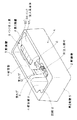
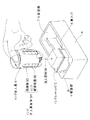
図1は本発明の一実施形態のインク注入具包装容器にインク注入具を収容した状態を示す斜視図であり、同図を参照して、本インク注入具包装容器A(以下、単に包装容器Aという)は、インクカートリッジ(以下、単にカートリッジという)にインクを注入するのに用いるインク注入具Bを包装するための直方体形状の容器である。また、本包装容器Aは、図2に示すように、インクカートリッジCを保持することができるようになっており、ユーザは、インクカートリッジCを手で持つことなく、インク注入具Bを用いて、インク注入が行えるようになっている。
【0018】
上記インク注入具Bは、金属製又は合成樹脂製の細い管状の注入部材91と、この注入部材91を通してインクを吸入し又吐出する弾性伸縮自在な蛇腹状のインク収容容器92と、このインク収容容器92の周囲を取り囲み注入部材91を固定した比較的剛性のある保持枠93とを備えている。インク収容容器92と保持枠93とによりインク注入具本体94を構成している。詳細には図示していないが、保持枠93は、インク収容容器92の上面を押す親指を所定深さまで導入させるための指導入溝を形成している。
【0019】
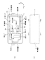
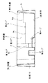
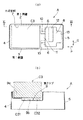
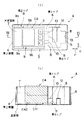
図3(a)は包装容器Aの平面図であり、図3(b)は包装容器Aの側面図である。また、図4は図3(a)のI −I 線に沿う断面図であり、図5(a)は図3(b)のII−II線に沿う断面図であり、図5(b)は図3(b)のIII −III 線に沿う断面図である。これらの図および図1を参照して、包装容器Aは、例えばポリスチレン樹脂等の合成樹脂製の1枚のシート材により形成されている。包装容器Aは、矩形形状の底面部1の四辺に、長手方向に沿う一対の第1側壁2,3と、短手方向に沿う一対の第2側壁4,5とを連続形成している。
【0020】
各側壁2〜5は、その上面において所定の幅の平坦部を有し、この平坦部の内外で下方へ折り曲げられた、断面略コ字形の基本形状を有している。すなわち、各側壁2〜5は、シート材の二重構造を呈しており、薄肉のシート材でありながら、十分な剛性が得られるようにされている。
上記一対の第1側壁2,3からは、互いに所定間隔を隔てて対向する一対の第1リブ6が突出形成されている。第1リブ6の配置位置は、長手方向の中央部よりも一方の第2側壁5寄りの位置であり、これら第1リブ6を境にして、包装容器Aの内部が、一方の第2側壁4側の大収容部7と、他方の第2側壁5側の小収容部8とに区画されている。
【0021】
大収容部7は、インク注入具本体94を収容するためのものであり、小収容部8は、主に注入部材91を配置するためのものである。
各収容部7,8の形状は、インク注入具Bが対象とする少なくとも一種類のカートリッジを、インク注入が可能な姿勢でそれぞれ保持できる形状に設定されているが、さらに多種類のカートリッジを保持することができるように、包装容器Aの内部に種々の工夫がこらされている。
【0022】
まず、大収容部7において、上記一対の第1側壁2,3にそれぞれ沿って底面部1から所定高さにまで突出する一対の第2リブ9が形成されている。これらの第2リブ9は、それぞれ複数段、例えば上段9aと下段9bの二段の高さに設定されている。
また、上記一対の第1リブ6,6同士の間の底面部1から各第1リブ6,6に沿ってそれぞれ立ち上がり、互いに所定間隔を隔てて対向する一対の第3リブ10が形成されている。これら第3リブ10,10間の底面部1から、第3リブ10よりも低い高さで立ち上がり、大収容部7側へ延びる第4リブ11が形成されている。
【0023】
上記小収容部8において、一方の第1側壁2から他方の第1側壁3に向かって両側壁2,3間の中間部まで延びる第5リブ12が形成されている。この第5リブ12は、底面部1から立ち上がって上記第3リブ10と略同一高さを有している(図4参照)。また、上記小収容部8において、第2側壁5に、一対の第1リブ6,6間の間隔に相当する幅で窪む凹部13が形成されている。
【0024】
次いで、大収容部7および小収容部8にカートリッジを収容保持する際の各側壁2〜5、上記の各リブ6〜12および凹部13の働きを示すために、代表的な5つのカートリッジC1〜C6の場合に則して、図6〜図13を参照しつつ説明する。
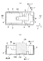
まず、平面図である図6(a)、およびこの図6(a)のIV−IV線に沿う断面図である図6(b)を参照して、カートリッジC1は、小収容部8に収容されている。カートリッジC1の長手方向の一端部は、凹部13内に収容され、これにより、カートリッジC1の長手方向Pへの移動が規制されている。また、カートリッジC1の短手方向Qへの移動は、凹部13の対向する一対の側面13a間と、一対の第1リブ6間にそれぞれ挟まれて規制されている。また、カートリッジC1の下面は、一対の第3リブ10と第5リブ12によって受けられ安定して支持されている。
【0025】
次いで、平面図である図7(a)、およびこの図7(a)のX −X 線に沿う断面図である図7(b)を参照して、本カートリッジC2を保持する形態が図6における保持の形態と異なるは、カートリッジC2の下面C21に突出部C22があり、この突出部C22(インクの吐出部である)が、第5リブ12と第2側壁5との間の空間に収容されていることである。この突出部C22は、第5リブ12の壁面に沿うようにされており、しかも、カートリッジC2の長手方向の一端部が第2側壁5の壁面に沿うようにされていることから、カートリッジC2の保持がより確実である。
【0026】
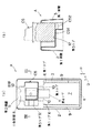
次いで、平面図である図8(a)、およびこの図8(a)のXI−XI線に沿う断面図である図8(b)を参照して、本カートリッジC3は、大収容部7に収容されている。カートリッジC3の幅方向(包装容器Aの短手方向Qに沿う方向)の両端部は、一対の第1側壁2,3間に挟まれて、短手方向Qへの移動が規制されている。また、カートリッジC3の長手方向(包装容器Aの長手方向Pに沿う方向)は、図8(b)に示すように、若干余裕が持たされているので、第2側壁4あるいは第1リブ6の何れか一方側へ寄せておけば、長手方向の一方側への移動を規制することができる。また、カートリッジC3の下面C31には、突出部C32(インクの吐出部である)が形成されている。カートリッジC3の下面C31は、第2リブ9の上段9aで受けられ、且つ突出部C32は、第2リブ9の下段9bで受けられている。これにより、カートリッジC3を略水平に安定して保持できるようになっている。
【0027】
次いで、平面図である図9(a)、およびこの図9(a)のXII −XII 線に沿う断面図である図9(b)を参照して、本カートリッジC4は、大収容部7に収容されている。カートリッジC4の幅方向(包装容器Aの短手方向Qに沿う方向)の両端部は、一対の第2リブ9,9間に挟まれて、短手方向Qへの移動が規制されている。また、カートリッジC4の長手方向(包装容器Aの長手方向Pに沿う方向)は、図9(b)に示すように、若干余裕が持たされているので、第2側壁4あるいは第1リブ6の何れか一方側へ寄せておけば、長手方向の一方側への移動を規制することができる〔図9(a)では第1リブ6側に寄せられている)。また、カートリッジC4の下面C41には、突出部C42(インクの吐出部である)が形成されている。カートリッジC4の下面C41は、第4リブ11の上面によって受けられ、且つ突出部C42は、包装容器Aの底面部1によって受けられている。これにより、カートリッジC4を略水平に安定して保持できるようになっている。
【0028】
次いで、平面図である図10(a)、およびこの図10(a)のXIII−XIII線に沿う断面図である図10(b)を参照して、本カートリッジC5は、小収容部8に収容されている。カートリッジC5の幅方向(包装容器Aの長手方向Pに沿う方向)の両端部は、第2側壁5と第1リブ6との間に挟まれて、長手方向Pへの移動が規制されている。また、カートリッジC5の下面C51には、突出部C52(インクの吐出部である)が形成されている。カートリッジC5の下面C51は、第5リブ12の上面によって受けられ、且つ突出部C52は、第5リブ12と第1側壁3との間の空間に押し込まれている。これにより、カートリッジC5を略水平に安定して保持できるようにされている。また、カートリッジC5の長手方向(包装容器Aの短手方向Qに沿う方向)は、上記突出部C52が、第5リブ12と第1側壁3との間の空間に略隙間なく嵌め込まれることにより、規制されている。
【0029】
次いで、平面図である図11(a)、およびこの図11(a)のXIIII −XIIII 線に沿う断面図である図11(b)を参照して、本カートリッジC6は、小収容部8および大収容部7に跨がって保持されている。すなわち、カートリッジC6の幅方向(包装容器Aの短手方向Qに沿う方向)の両端部は、一対の第3リブ10,10間に挟まれて、短手方向Qへの移動を規制されている。また、カートリッジC6の長手方向(包装容器Aの長手方向Pに沿う方向)の一端部は、第5リブ12の壁面に当接されて、長手方向Pへの移動を規制されている。また、カートリッジC6の下面C61には、突出部C62(インクの吐出部である)が形成されている。カートリッジC6の下面C61は、第4リブ11の上面によって受けられ、且つ突出部C62は、包装容器Aの底面部1によって受けられている。これにより、カートリッジC4を略水平に安定して保持できるようになっている。
【0030】
本実施形態によれば、例示した図6〜図11のようにして、複数のカートリッジを保持することができる。そして、このようにして保持したカートリッジに対して、図2に示すようにして、インク注入具Bを用いて、インクを再充填することができ、汎用性が高い。しかも、このとき、従来のように片手でインクカートリッジCを保持しておく必要がなく、インク注入を非常に容易に行うことができる。また、仮に、インク注入時にインクカートリッジCからインクがあふれ出たとしても、本包装容器Aによって受け止めることができる結果、手やテーブルを汚すことがない。
【0031】
特に、図8および図9に示すように、一対の第1側壁2,3間の幅を持つタイプのカートリッジC3と、一対の第2リブ9,9間の幅を持つタイプのカートリッジC4を、大収容部7に保持できることになり、適合可能なインクカートリッジの種類を増やすことができる。
また、図8に示すように、インクカートリッジC3の下面C31が突出部C32等の凹凸形状を有している場合に、この凹凸形状に、例えば上端9aと下段9bのように複数段の高さに設定した第2リブ9を適合させることにより、凹凸形状を有するインクカートリッジC3を安定して保持することができる。このことに関しては、図7〜図11の何れの保持の形態についても同様である。なお、3段以上に高さを異ならせても良い。
【0032】
また、図6および図7のように大収容部7又は小収容部8に収容しきれないタイプのインクカートリッジC1,C2の一部を、一対の第1リブ6,6間に挿通させて保持する場合において、挿通されるインクカートリッジC1,C2の上記一部を、上記一対の第3リブ10によって受けることができ、インクカートリッジC1,C2を安定して保持することができる。
【0033】
また、図11のように一方の収容部7,8のみでは保持が十分でなかったりするタイプのインクカートリッジC6を、一対の第3リブ10,10間に挿通させて保持する場合において、挿通されるインクカートリッジC6の上記一部を、第4リブによって受けることができ、インクカートリッジC6を安定して保持することができる。
【0034】
また、図1に示すように、大収容部7において、第2側壁4と第3リブ10の壁面との間でインク注入具Bの長手方向移動を規制し、インク収容具Bを安定して収容することができる。
また、図6および図7に示すように、小収容部8において、第3リブ10と第5リブ12とによって、インクカートリッジC1,C2を底面部1から浮かした状態に受け、安定して保持することができる。また、インクカートリッジC2に底面部1側へ突出する突出部C22があっても、インクカートリッジC2自体を底面部1から浮かせて保持しているので、突出部C22の存在が邪魔にならず、安定して保持することができる。
【0035】
また、第2側壁5に、一対の第1リブ6,6間の間隔に相当する幅で窪む凹部13を設けたので、図6および図7のように、上記一対のリブ6,6間から上記凹部13内に至るまで延びるタイプのインクカートリッジC1,C2を、安定して保持することができる。
なお、本発明は上記実施形態に限定されるものではなく、本発明の範囲で種々の変更を施すことができる。
【0036】
【発明の効果】
請求項1記載の発明では、インク注入具を用いてインク注入を行う際に、インクカートリッジを大収容部又は小収容部に保持しておくことができるので、従来のように片手でインクカートリッジを保持しておく必要がなく、インク注入を非常に容易に行うことができる。また、仮に、インク注入時にインクカートリッジからインクがあふれ出たとしても、容器によって受け止めることができる結果、手やテーブルを汚すことがない。さらに、複数のインクカートリッジに対応でき、汎用性が高い。
【0037】
請求項2記載の発明では、一対の第1側壁間の幅を持つタイプと、一対の第2リブ間の幅を持つタイプの双方のインクカートリッジを、大収容部に保持できることになり、適合可能なインクカートリッジの種類を増やすことができる。
請求項3記載の発明では、インクカートリッジの下面が凹凸形状を有している場合に、この凹凸形状に、複数段の高さに設定した第2リブを適合させることにより、凹凸形状を有するインクカートリッジを安定して保持することができる。
【0038】
請求項4記載の発明では、大収容部又は小収容部に収容しきれないタイプのインクカートリッジの一部を、一対の第1リブ間に挿通させて保持する場合において、第1リブ間に挿通されるインクカートリッジの上記一部を、上記一対の第3リブによって受けることができ、インクカートリッジを安定して保持することができる。
【0039】
請求項5記載の発明では、大収容部において、第2側壁と第3リブの端面との間でインク注入具の長手方向移動を規制し、インク収容具を安定して収容することができる。
請求項6記載の発明では、小収容部において、第3リブと第5リブとによって、インクカートリッジを底面部から浮かした状態に受け、安定して保持することができる。また、インクカートリッジに底面部側へ突出する突出部があっても、インクカートリッジ自体を底面部から浮かせて保持しているので、突出部の存在が邪魔にならず、安定して保持することができる。
【0040】
請求項7記載の発明では、小収容部において、上記一対のリブ間から上記凹部内に至るまで延びるタイプのインクカートリッジを、安定して保持することができる。
【図面の簡単な説明】
【図1】本発明の一実施形態のインク注入具包装容器がインク注入具Bを収容した状態を示す斜視図である。
【図2】包装容器によってカートリッジを保持してインク注入する際の斜視図である。
【図3】(a)は包装容器の平面図であり、(b)は包装容器の側面図である。
【図4】図3のI −I 線に沿う断面図である。
【図5】(a)は図3(b)のII−II線に沿う断面図であり、(b)は図3(b)のIII −III 線に沿う断面図である。
【図6】(a)は一のタイプのカートリッジを保持した包装容器の平面図であり、(b)は(a)のIV−IV線に沿う断面図である。
【図7】(a)は他のタイプのカートリッジを保持した包装容器の平面図であり、(b)は(a)のX −X 線に沿う断面図である。
【図8】(a)はさらに他のタイプのカートリッジを保持した包装容器の平面図であり、(b)は(a)のXI−XI線に沿う断面図である。
【図9】(a)はさらに他のタイプのカートリッジを保持した包装容器の平面図であり、(b)は(a)のXII −XII 線に沿う断面図である。
【図10】(a)はさらに他のタイプのカートリッジを保持した包装容器の平面図であり、(b)は(a)のXIII−XIII線に沿う断面図である。
【図11】(a)はさらに他のタイプのカートリッジを保持した包装容器の平面図であり、(b)は(a)のXIIII −XIIII 線に沿う断面図である。
【符号の説明】
B インク注入具
91 注入部材
94 インク注入具本体
1 底面部
2,3 第1側壁
4,5 第2側壁
6 第1リブ
7 大収容部
8 小収容部
9 第2リブ
9a 上段
9b 下段
10 第3リブ
11 第4リブ
12 第5リブ
13 凹部[0001]
BACKGROUND OF THE INVENTION
The present invention relates to an ink injector packaging container for packaging an ink injector for supplying ink to an ink cartridge.
[0002]
[Prior art]
In recent years, ink jet printers have become widespread. This type of printer is equipped with an ink cartridge filled with ink and supplies ink to the print head side. In reality, such ink cartridges are disposable.
[0003]
However, ink cartridges are quite expensive, and it has been very unsatisfactory for users to frequently replace such expensive ink cartridges. In particular, color ink cartridges originally had a small amount of each color, and used colors were liable to be biased, so early replacement was necessary.
[0004]
However, the ink cartridge simply consumes the ink contained therein, and the main body of the cartridge is still usable.
In view of such circumstances, as an ink injecting device for smoothly injecting ink, a part in which an injecting member is attached to the lower part of a bellows-like stretchable and synthetic resin ink container is commercially available. ing.
[0005]
A user who has purchased such an ink injector makes a hole in the upper surface of the cartridge main body with a cone or a drill, and then holds the cartridge main body on the table with one hand and the ink injector with the other hand. Ink is injected by inserting the injection member of the ink injection tool into the hole of the main body of the cartridge.
[0006]
[Problems to be solved by the invention]
However, if the ink injection speed is too fast or the cartridge is full of ink, the ink may overflow from the cartridge. In this case, the hand or table holding the cartridge is soiled with ink, and later Cleaning up is very troublesome.
[0007]
On the other hand, a container for packaging such an ink injector merely performs a function of packaging the ink injector.
The inventor of the present application thought that the ink injection work could be facilitated by using this packaging container. The present invention has been made based on such an idea, and an object of the present invention is to provide an ink filler packaging container that can easily perform an ink injection operation.
[0008]
[Means for Solving the Problems]
To achieve the above objective,
1) The ink injector packaging container according to claim 1 is a rectangular parallelepiped container for packaging an ink injector for injecting ink into an ink cartridge through an injection member fixed to the ink injector body. A pair of first side walls extending along the longitudinal direction and a pair of second side walls extending along the short side direction are extended from the four sides of the bottom surface portion of the base plate, and project from the pair of first side walls and face each other with a predetermined distance therebetween. A pair of first ribs, and by these first ribs, the inside of the container is divided into a large accommodating portion for accommodating the ink injecting tool body and a small accommodating portion for disposing the injection member, The shape of the storage portion is set such that at least one kind of ink cartridge targeted by the ink injection tool can be held in a posture capable of ink injection.
[0009]
In the above configuration, since the ink cartridge can be held in a posture capable of ink injection by the large storage portion or the small storage portion after the ink injection device is taken out, the ink injection using the ink injection device is very Can be done easily. Further, even if ink overflows from the ink cartridge, the ink is accumulated in the packaging container and does not stain the hands or the table. Furthermore, since at least one type of ink cartridge is adapted to each of the large accommodating portion and the small accommodating portion, a plurality of types of ink cartridges can be handled.
[0010]
Here, the predetermined interval separating the pair of first ribs means an interval at which a part of a type of ink cartridge that cannot be accommodated in the large accommodating portion or the small accommodating portion can be inserted and held.
2) The ink filling device packaging container according to
[0011]
In the above configuration, both the type of ink cartridge having the width between the pair of first side walls and the type of having the width between the pair of second ribs can be held in the large accommodating portion. The number can be increased.
3) An ink injecting device packaging container according to
[0012]
In the above configuration, when the lower surface of the ink cartridge has a concavo-convex shape, the concavo-convex shape of the ink cartridge having a concavo-convex shape is stabilized by adapting the second rib set to a plurality of heights to the concavo-convex shape. Can be held.
4) An ink injecting device packaging container according to
[0013]
In the above configuration, when a part of the type of ink cartridge that cannot be accommodated in the large accommodating portion or the small accommodating portion is inserted and held between the pair of first ribs, the ink cartridge is inserted between the first ribs. Can be received by the pair of third ribs, and the ink cartridge can be stably held.
5) The ink filler packaging container according to
[0014]
In the above configuration, in the large storage portion, the movement of the ink injection tool in the longitudinal direction is restricted between the second side wall and the end surface of the third rib, and the ink storage device can be stably stored.
6) The ink injecting device packaging container according to
[0015]
In the above configuration, in the small accommodating portion, the ink cartridge can be received from the bottom surface portion and stably held by the third rib and the fifth rib. Even if the ink cartridge has a protruding portion that protrudes toward the bottom surface, the ink cartridge itself is held floating from the bottom surface, so that the presence of the protruding portion does not get in the way and can be held stably. it can.
[0016]
7) The ink injecting device packaging container according to
In the above configuration, the ink cartridge that extends from between the pair of ribs to the inside of the concave portion can be stably held in the small accommodating portion.
[0017]
DETAILED DESCRIPTION OF THE INVENTION
Preferred embodiments of the present invention will be described with reference to the accompanying drawings.
FIG. 1 is a perspective view showing a state in which an ink injector is accommodated in an ink injector packaging container according to an embodiment of the present invention. Referring to FIG. 1, the ink injector packaging container A (hereinafter simply referred to as a packaging container). A) is a rectangular parallelepiped container for packaging an ink injection tool B used for injecting ink into an ink cartridge (hereinafter simply referred to as a cartridge). Further, as shown in FIG. 2, the packaging container A can hold the ink cartridge C, and the user uses the ink injection tool B without holding the ink cartridge C by hand. Ink can be injected.
[0018]
The ink injection tool B includes a thin tubular injection member 91 made of metal or synthetic resin, an elastically stretchable bellows-like
[0019]
3A is a plan view of the packaging container A, and FIG. 3B is a side view of the packaging container A. FIG. 4 is a cross-sectional view taken along line I-I in FIG. 3A, FIG. 5A is a cross-sectional view taken along line II-II in FIG. 3B, and FIG. These are sectional drawings which follow the III-III line of Drawing 3 (b). With reference to these figures and FIG. 1, the packaging container A is formed of one sheet material made of synthetic resin such as polystyrene resin. The packaging container A continuously forms a pair of
[0020]
Each of the
From the pair of
[0021]
The large
The shape of each of the
[0022]
First, in the large
Further, a pair of
[0023]
In the small
[0024]
Next, in order to show the functions of the
First, with reference to FIG. 6A which is a plan view and FIG. 6B which is a cross-sectional view taken along the line IV-IV of FIG. Has been. One end portion of the cartridge C1 in the longitudinal direction is accommodated in the
[0025]
Next, referring to FIG. 7A which is a plan view and FIG. 7B which is a cross-sectional view taken along the line X-X of FIG. 7A, a configuration for holding the cartridge C2 is shown in FIG. Unlike the holding form in FIG. 2, there is a protruding portion C22 on the lower surface C21 of the cartridge C2, and this protruding portion C22 (which is an ink discharge portion) is accommodated in the space between the
[0026]
Next, with reference to FIG. 8A which is a plan view and FIG. 8B which is a cross-sectional view taken along the line XI-XI of FIG. Contained. Both ends of the cartridge C3 in the width direction (the direction along the short direction Q of the packaging container A) are sandwiched between the pair of
[0027]
Next, with reference to FIG. 9A which is a plan view and FIG. 9B which is a cross-sectional view taken along the line XII-XII of FIG. Contained. Both ends of the cartridge C4 in the width direction (the direction along the short direction Q of the packaging container A) are sandwiched between the pair of
[0028]
Next, referring to FIG. 10A which is a plan view and FIG. 10B which is a cross-sectional view taken along the line XIII-XIII of FIG. Contained. Both ends of the cartridge C5 in the width direction (the direction along the longitudinal direction P of the packaging container A) are sandwiched between the
[0029]
Next, referring to FIG. 11 (a) which is a plan view and FIG. 11 (b) which is a cross-sectional view taken along the line XIIII-XIIII of FIG. 11 (a), the cartridge C6 includes the small
[0030]
According to the present embodiment, a plurality of cartridges can be held as illustrated in FIGS. Then, the cartridge held in this way can be refilled with ink using the ink injection tool B as shown in FIG. In addition, at this time, it is not necessary to hold the ink cartridge C with one hand as in the prior art, and ink injection can be performed very easily. In addition, even if ink overflows from the ink cartridge C at the time of ink injection, it can be received by the packaging container A, so that hands and tables are not soiled.
[0031]
In particular, as shown in FIGS. 8 and 9, a cartridge C3 having a width between the pair of
Further, as shown in FIG. 8, when the lower surface C31 of the ink cartridge C3 has a concavo-convex shape such as the protrusion C32, the concavo-convex shape has a plurality of heights such as an
[0032]
6 and 7, a part of the type of ink cartridges C1 and C2 that cannot be accommodated in the large
[0033]
Further, as shown in FIG. 11, when the ink cartridge C6 of a type that is not sufficiently held only by one of the
[0034]
Further, as shown in FIG. 1, in the
As shown in FIGS. 6 and 7, the
[0035]
Moreover, since the recessed
In addition, this invention is not limited to the said embodiment, A various change can be given in the range of this invention.
[0036]
【The invention's effect】
According to the first aspect of the present invention, the ink cartridge can be held in the large accommodating portion or the small accommodating portion when the ink is injected using the ink injecting tool. There is no need to hold the ink, and ink can be injected very easily. Further, even if ink overflows from the ink cartridge at the time of ink injection, it can be received by the container, so that hands and tables are not soiled. Furthermore, it is compatible with a plurality of ink cartridges and is highly versatile.
[0037]
According to the second aspect of the present invention, both the type of ink cartridge having a width between the pair of first side walls and the type having a width between the pair of second ribs can be held in the large accommodating portion and can be adapted. The number of types of ink cartridges can be increased.
According to a third aspect of the present invention, when the lower surface of the ink cartridge has a concavo-convex shape, an ink having a concavo-convex shape is obtained by adapting the second rib set to a plurality of heights to the concavo-convex shape. The cartridge can be stably held.
[0038]
According to the fourth aspect of the present invention, when a part of an ink cartridge that cannot be accommodated in the large accommodating portion or the small accommodating portion is inserted and held between the pair of first ribs, the ink cartridge is inserted between the first ribs. The part of the ink cartridge to be used can be received by the pair of third ribs, and the ink cartridge can be stably held.
[0039]
According to the fifth aspect of the present invention, the longitudinal movement of the ink injection tool can be regulated between the second side wall and the end surface of the third rib in the large storage portion, and the ink storage device can be stably stored.
In the invention according to
[0040]
According to the seventh aspect of the present invention, the ink cartridge of the type that extends from between the pair of ribs to the inside of the concave portion can be stably held in the small accommodating portion.
[Brief description of the drawings]
FIG. 1 is a perspective view showing a state in which an ink injector B is accommodated in an ink injector packaging container according to an embodiment of the present invention.
FIG. 2 is a perspective view when ink is injected while a cartridge is held by a packaging container.
3A is a plan view of a packaging container, and FIG. 3B is a side view of the packaging container.
4 is a cross-sectional view taken along the line II of FIG.
5A is a cross-sectional view taken along line II-II in FIG. 3B, and FIG. 5B is a cross-sectional view taken along line III-III in FIG. 3B.
6A is a plan view of a packaging container holding one type of cartridge, and FIG. 6B is a cross-sectional view taken along line IV-IV in FIG.
7A is a plan view of a packaging container holding another type of cartridge, and FIG. 7B is a cross-sectional view taken along line XX in FIG. 7A.
8A is a plan view of a packaging container holding still another type of cartridge, and FIG. 8B is a cross-sectional view taken along line XI-XI in FIG. 8A.
9A is a plan view of a packaging container holding still another type of cartridge, and FIG. 9B is a sectional view taken along line XII-XII in FIG. 9A.
10A is a plan view of a packaging container holding still another type of cartridge, and FIG. 10B is a sectional view taken along line XIII-XIII in FIG. 10A.
11A is a plan view of a packaging container holding still another type of cartridge, and FIG. 11B is a sectional view taken along line XIIII-XIIII in FIG.
[Explanation of symbols]
B Ink filling tool 91 Filling member 94 Ink filling tool body 1
Claims (7)
矩形形状の底面部の四辺に、長手方向に沿う一対の第1側壁と短手方向に沿う一対の第2側壁とを延設しており、
上記一対の第1側壁から突出し互いに所定間隔を隔てて対向する一対の第1リブを有し、これら第1リブによって、容器内部がインク注入具本体を収容するための大収容部と、注入部材を配置するための小収容部に区画されており、
各収容部の形状は、本インク注入具が対象とする少なくとも一種類のインクカートリッジを、インク注入が可能な姿勢でそれぞれ保持できる形状に設定されていることを特徴とするインク注入具包装容器。A rectangular parallelepiped container for packaging an ink injector that injects ink into an ink cartridge through an injection member fixed to the ink injector body,
A pair of first side walls along the longitudinal direction and a pair of second side walls along the short side direction are extended on the four sides of the bottom surface of the rectangular shape,
A pair of first ribs that protrude from the pair of first side walls and face each other with a predetermined gap therebetween, and by these first ribs, a large accommodating portion for accommodating the ink injector main body inside the container, and an injection member Is divided into small accommodating parts for placing
The shape of each storage part is set to a shape that can hold at least one type of ink cartridge targeted by the ink injection tool in a posture capable of ink injection, respectively.
Priority Applications (1)
| Application Number | Priority Date | Filing Date | Title |
|---|---|---|---|
| JP20063396A JP3774512B2 (en) | 1996-07-30 | 1996-07-30 | Ink filling device packaging container |
Applications Claiming Priority (1)
| Application Number | Priority Date | Filing Date | Title |
|---|---|---|---|
| JP20063396A JP3774512B2 (en) | 1996-07-30 | 1996-07-30 | Ink filling device packaging container |
Publications (2)
| Publication Number | Publication Date |
|---|---|
| JPH1045184A JPH1045184A (en) | 1998-02-17 |
| JP3774512B2 true JP3774512B2 (en) | 2006-05-17 |
Family
ID=16427637
Family Applications (1)
| Application Number | Title | Priority Date | Filing Date |
|---|---|---|---|
| JP20063396A Expired - Fee Related JP3774512B2 (en) | 1996-07-30 | 1996-07-30 | Ink filling device packaging container |
Country Status (1)
| Country | Link |
|---|---|
| JP (1) | JP3774512B2 (en) |
Families Citing this family (3)
| Publication number | Priority date | Publication date | Assignee | Title |
|---|---|---|---|---|
| JP5390119B2 (en) * | 2008-05-01 | 2014-01-15 | エステー産業株式会社 | Refilling liquid ink in used ink cartridges |
| US10350901B2 (en) * | 2016-06-10 | 2019-07-16 | Seiko Epson Corporation | Ink bottle |
| CN111746139B (en) * | 2016-06-10 | 2022-05-13 | 精工爱普生株式会社 | Ink replenishment container |
-
1996
- 1996-07-30 JP JP20063396A patent/JP3774512B2/en not_active Expired - Fee Related
Also Published As
| Publication number | Publication date |
|---|---|
| JPH1045184A (en) | 1998-02-17 |
Similar Documents
| Publication | Publication Date | Title |
|---|---|---|
| JP2625127B2 (en) | Ink supply system | |
| EP1114725B1 (en) | ink-jet pen with two-part lid and techniques for filling | |
| EP0773109B1 (en) | Ink refilling method and apparatus, ink container refilled therewith and ink jet apparatus comprising ink refilling apparatus | |
| CA2141067C (en) | Method of refilling ink-jet printer cartridges | |
| CA2396930C (en) | Ink-jet print cartridge having a low profile | |
| JP2017193105A (en) | Liquid container unit | |
| JP2000296623A (en) | Liquid container, inkjet head cartridge, liquid jet recording device | |
| US5812165A (en) | Leak resistant ink-jet pen | |
| JP6969162B2 (en) | Waste liquid container and liquid injection device | |
| CN104972764B (en) | Liquid housing container | |
| JP3774512B2 (en) | Ink filling device packaging container | |
| US20140125742A1 (en) | Ink Cartridge for Printer | |
| JP7608202B2 (en) | LIQUID CONTAINER AND LIQUID EJECTION APPARATUS | |
| AU3332500A (en) | Device and method of refilling ink into ink cartridges for ink-jet printers | |
| WO2007003908A1 (en) | An ink cartridge and a memory device | |
| JP2013010540A (en) | Jetting head for aerosol container | |
| US5070347A (en) | Cylindrical wall member for ink liquid resevoir mounted on a carriage in an ink jet system printer | |
| KR101587997B1 (en) | Continuous hand writing marker pen | |
| US7328986B2 (en) | Inkjet printer ink cartridge | |
| CN113895152B (en) | Waste liquid container and liquid ejection device | |
| US20040080591A1 (en) | Ink cartridge having an appropriate negative pressure | |
| JP2000238750A (en) | Partitioning material for box | |
| KR100321309B1 (en) | Refill cartridges for inkjet printers | |
| US7168801B2 (en) | Ink cartridge | |
| US12296601B2 (en) | Liquid storage container and printing apparatus |
Legal Events
| Date | Code | Title | Description |
|---|---|---|---|
| A977 | Report on retrieval |
Free format text: JAPANESE INTERMEDIATE CODE: A971007 Effective date: 20060130 |
|
| TRDD | Decision of grant or rejection written | ||
| A01 | Written decision to grant a patent or to grant a registration (utility model) |
Free format text: JAPANESE INTERMEDIATE CODE: A01 Effective date: 20060207 |
|
| A61 | First payment of annual fees (during grant procedure) |
Free format text: JAPANESE INTERMEDIATE CODE: A61 Effective date: 20060220 |
|
| R150 | Certificate of patent (=grant) or registration of utility model |
Free format text: JAPANESE INTERMEDIATE CODE: R150 |
|
| FPAY | Renewal fee payment (prs date is renewal date of database) |
Free format text: PAYMENT UNTIL: 20090224 Year of fee payment: 3 |
|
| FPAY | Renewal fee payment (prs date is renewal date of database) |
Free format text: PAYMENT UNTIL: 20100224 Year of fee payment: 4 |
|
| FPAY | Renewal fee payment (prs date is renewal date of database) |
Free format text: PAYMENT UNTIL: 20100224 Year of fee payment: 4 |
|
| FPAY | Renewal fee payment (prs date is renewal date of database) |
Free format text: PAYMENT UNTIL: 20110224 Year of fee payment: 5 |
|
| FPAY | Renewal fee payment (prs date is renewal date of database) |
Free format text: PAYMENT UNTIL: 20110224 Year of fee payment: 5 |
|
| FPAY | Renewal fee payment (prs date is renewal date of database) |
Free format text: PAYMENT UNTIL: 20120224 Year of fee payment: 6 |
|
| FPAY | Renewal fee payment (prs date is renewal date of database) |
Free format text: PAYMENT UNTIL: 20130224 Year of fee payment: 7 |
|
| FPAY | Renewal fee payment (prs date is renewal date of database) |
Free format text: PAYMENT UNTIL: 20140224 Year of fee payment: 8 |
|
| R250 | Receipt of annual fees |
Free format text: JAPANESE INTERMEDIATE CODE: R250 |
|
| LAPS | Cancellation because of no payment of annual fees |