JP3774548B2 - Pneumatic radial tire and manufacturing method thereof - Google Patents
Pneumatic radial tire and manufacturing method thereof Download PDFInfo
- Publication number
- JP3774548B2 JP3774548B2 JP20495197A JP20495197A JP3774548B2 JP 3774548 B2 JP3774548 B2 JP 3774548B2 JP 20495197 A JP20495197 A JP 20495197A JP 20495197 A JP20495197 A JP 20495197A JP 3774548 B2 JP3774548 B2 JP 3774548B2
- Authority
- JP
- Japan
- Prior art keywords
- carcass
- tire
- cord
- layer
- belt
- Prior art date
- Legal status (The legal status is an assumption and is not a legal conclusion. Google has not performed a legal analysis and makes no representation as to the accuracy of the status listed.)
- Expired - Fee Related
Links
- 238000004519 manufacturing process Methods 0.000 title claims description 12
- 238000004073 vulcanization Methods 0.000 claims description 17
- 229910000831 Steel Inorganic materials 0.000 claims description 13
- 239000010959 steel Substances 0.000 claims description 13
- 239000011324 bead Substances 0.000 claims description 10
- 239000000463 material Substances 0.000 claims description 8
- 238000000034 method Methods 0.000 claims description 7
- 238000000465 moulding Methods 0.000 description 12
- 230000020169 heat generation Effects 0.000 description 5
- 238000011156 evaluation Methods 0.000 description 3
- 230000007423 decrease Effects 0.000 description 2
- 230000000694 effects Effects 0.000 description 2
- 239000004677 Nylon Substances 0.000 description 1
- 229920000297 Rayon Polymers 0.000 description 1
- NINIDFKCEFEMDL-UHFFFAOYSA-N Sulfur Chemical compound [S] NINIDFKCEFEMDL-UHFFFAOYSA-N 0.000 description 1
- 239000004760 aramid Substances 0.000 description 1
- 229920003235 aromatic polyamide Polymers 0.000 description 1
- 239000000835 fiber Substances 0.000 description 1
- 229920001778 nylon Polymers 0.000 description 1
- 230000002093 peripheral effect Effects 0.000 description 1
- 229920000728 polyester Polymers 0.000 description 1
- 238000003825 pressing Methods 0.000 description 1
- 239000002964 rayon Substances 0.000 description 1
- 230000003014 reinforcing effect Effects 0.000 description 1
- 229910052717 sulfur Inorganic materials 0.000 description 1
- 239000011593 sulfur Substances 0.000 description 1
- 238000010998 test method Methods 0.000 description 1
Images



Landscapes
- Tires In General (AREA)
- Tyre Moulding (AREA)
Description
【0001】
【発明の属する技術分野】
本発明は、トラック・バス等に使用される重荷重用として好適な空気入りラジアルタイヤ及びその製造方法に関し、さらに詳しくは、トレッド部における発熱を増大させることなく、加硫成形時のリフト張力によってショルダー部付近でカーカスコードにウェーブが発生することを防止するようにした空気入りラジアルタイヤ及びその製造方法に関する。
【0002】
【従来の技術】
従来の空気入りラジアルタイヤは、一般にトレッドとカーカス層との間に、スチールコードがタイヤ周方向に対して傾斜する少なくとも2層のベルト層を互いに交差するように配置する一方で、カーカス層のカーカスコードをタイヤ周方向に対して略90°に配置した構成になっている。このように構成される空気入りラジアルタイヤを製造する場合、未加硫のグリーンタイヤを金型内に挿入し、その内側からリフト張力を掛けて金型内面に押し当てることにより製品タイヤの形状に成形している。
【0003】
しかしながら、カーカス層に隣接するベルト層のタイヤ周方向に対するコード角度が小さい場合、加硫成形時のリフト張力によってベルト層のコード角度が変化し、このベルト層の角度変化に引きずられる形でショルダー部付近でカーカスコードにウェーブが発生するという問題があった。このようにショルダー部付近でカーカスコードにウェーブが発生すると、タイヤ充填内圧によりカーカスコードが真っ直ぐになろうとする力が作用するためベルト端領域に剪断歪みを生じ、かつカーカスコードの余長ペリフェリーが走行時に外周成長しようとするため、ベルト層の耐久性が低下してしまう。
【0004】
そこで、上記問題の対策として、ハイアングルベルトをカーカス層の外側に追加することにより、ベルト層の角度変化がカーカスコードに伝達されないようにすることが考えられる。しかし、荒地走行に使用される重荷重用空気入りラジアルタイヤでは、耐カット性やエンベロープ性を確保する必要があるため上記ハイアングルベルトを採用することは不適当であり、しかもハイアングルベルトの追加によってトレッド厚さが増大するためトレッド部における発熱量が増大してしまう。
【0005】
また、カーカス層とベルト層との間にクッションゴムを介在させることにより、ベルト層の角度変化がカーカスコードに伝達されないようにすることが可能である。しかし、この場合もクッションゴムによってトレッド厚さが増大するため、トレッド部における発熱量が増大してしまう。
【0006】
【発明が解決しようとする課題】
本発明の目的は、トレッド部における発熱を増大させることなく、加硫成形時のリフト張力によってショルダー部付近でカーカスコードにウェーブが発生することを防止可能にした空気入りラジアルタイヤ及びその製造方法を提供することにある。
【0007】
【課題を解決するための手段】
上記目的を達成するための本発明の空気入りラジアルタイヤは、左右一対のビード部間にカーカスコードをタイヤ径方向に配列したカーカス層を装架すると共に、トレッド部における前記カーカス層の外側にスチールコードからなる少なくとも2層のベルト層を層間でコードが互いに交差するように配置し、かつ前記カーカス層に隣接するベルト層のタイヤ周方向に対するコード角度を45°以下にした空気入りラジアルタイヤにおいて、前記カーカス層に隣接するベルト層の幅に対して35〜70%の中央領域で前記カーカスコードを波状に型付けしたことを特徴とするものである。
【0008】
また、本発明の空気入りラジアルタイヤの製造方法は、左右一対のビード部間にカーカスコードをタイヤ径方向に配列したカーカス層を装架すると共に、トレッド部における前記カーカス層の外側にスチールコードからなる少なくとも2層のベルト層を層間でコードが互いに交差するように配置し、かつ前記カーカス層に隣接するベルト層のタイヤ周方向に対するコード角度を45°以下にした空気入りラジアルタイヤの製造方法において、前記カーカス層に隣接するベルト層の幅に対して35〜70%の中央領域でカーカスコードを予め波状に型付けしたカーカス材を用いて未加硫のグリーンタイヤを成形し、該グリーンタイヤを加硫成形するようにしたことを特徴とするものである。
【0009】
このようにカーカス層に隣接するベルト層のタイヤ周方向に対するコード角度を45°以下にした空気入りラジアルタイヤを製造するに当たって、カーカス層に隣接するベルト層の幅に対して35〜70%の中央領域でカーカスコードを予め波状に型付けしたカーカス材を用いて未加硫のグリーンタイヤを成形し、該グリーンタイヤを加硫成形するようにしたことにより、加硫成形時のリフト張力によってベルト層のコード角度が変化しても、そのベルト層の角度変化による歪みを前記中央領域におけるカーカスコードの波状部分が吸収するので、ショルダー部付近でカーカスコードにウェーブが発生することを防止できる。また、上記構成によれば、タイヤ部材を新たに追加する必要がないので、トレッド部における発熱量を増大させることはない。
【0010】
【発明の実施の形態】
以下、本発明の構成について添付の図面を参照して詳細に説明する。
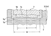
図1〜図3は、本発明の実施形態からなる重荷重用空気入りラジアルタイヤを例示するものである。図において、左右一対のビード部1,1間には複数本のカーカスコード2をタイヤ径方向に配列したカーカス層3が装架されており、このカーカス層3のタイヤ幅方向両端部がそれぞれビードコア4の周りにタイヤ内側から外側へ巻き上げられている。また、ビード部1にはカーカス層3を包み込むように補強層5が設けられている。
【0011】
トレッド部6におけるカーカス層3の外側には、それぞれ複数本のスチールコードからなる4層のベルト層7a〜7dが設けられている。これらベルト層7a〜7dは、そのコードがタイヤ周方向に対して傾斜し、かつ層間でコードが互いに交差するように配置されている。一方、カーカスコード2は、カーカス層3に隣接するベルト層7aのベルト幅Wに対して35〜70%の中央領域Cにおいて波状に型付けされており、この中央領域Cの外側ではタイヤ周方向に対する角度が実質的に90°となるように配列されている。
【0012】
カーカス層側から数えて第1番目のベルト層7aは、タイヤ周方向に対するコード角度が22〜45°に設定されている。第2番目のベルト層7bは、タイヤ周方向に対するコード角度が18〜27°に設定されている。第3番目のベルト層7cは、タイヤ周方向に対するコード角度が14〜24°に設定されている。第4番目のベルト層7dは、タイヤ周方向に対するコード角度が18〜27°に設定されている。これらベルト層7a〜7dのコード角度は、重荷重用として好適な範囲に設定されている。
【0013】
本発明では、上記空気入りラジアルタイヤを製造するに当たって、カーカス層3に隣接するベルト層7aのベルト幅Wに対して35〜70%の中央領域Cでカーカスコード2を予め波状に型付けしたカーカス材30を用いて未加硫のグリーンタイヤを成形する。そして、この未加硫のグリーンタイヤを金型内に挿入し、その内側からブラダー等を介してリフト張力を掛けて金型内面に押し当てることによりトレッド部6に溝8などを成形し、これを加硫する。
【0014】
このように中央領域Cでカーカスコード2を予め波状に型付けすることにより、加硫成形時のリフト張力によってベルト層7aのコード角度が変化しても、そのベルト層7aの角度変化による歪みを中央領域Cにおけるカーカスコード2の波状部分が吸収するので、ショルダー部付近でカーカスコード2にウェーブが発生することを防止できる。
【0015】
しかも、上記中央領域Cではカーカス張力が殆ど掛からないためカーカスコード2を波状に型付けしても走行時に外周成長することはない。従って、カーカス層3の外側に設けたベルト層7a〜7dの耐久性を向上することができる。また、上記構成によれば、従来のようにクッションゴムやハイアングルベルトを追加する必要がないので、トレッド部6の厚さを従来に比べて薄くし、トレッド部6における発熱量を低くすることが可能であり、しかも追加部材の分だけ材料コストを低減することが可能である。
【0016】
本発明において、カーカスコード2を波状に型付けする中央領域Cは、カーカス層3に隣接するベルト層7aのベルト幅Wに対して35〜70%の範囲に設定する。すなわち、リフト張力によるベルト層7aの角度変化はタイヤ幅方向に均一ではなく、特にタイヤ幅方向中央付近で大きくなるため、上記中央領域Cはベルト層7aのベルト幅Wの少なくとも35%をカバーする必要がある。一方、中央領域Cがベルト層7aのベルト幅Wの70%を超えると加硫成形後に残存する波状部分の余長ペリフェリーが走行時に外周成長しようとするため、ベルト層の耐久性が低下してしまう。
【0017】
中央領域Cにおけるカーカスコード2の振幅aは加硫前でカーカスコード径Φの4〜8倍にすることが好ましい。このカーカスコード2の振幅aがカーカスコード径Φの4倍未満であるとベルト層7aの角度変化による歪みを吸収することができず、逆に8倍を超えるとクラウン部における余長ペリフェリーが多過ぎるため走行時に外周成長する虞がある。また、カーカスコード2の波長λは振幅aの4〜10倍にすることが好ましい。
【0018】
上記カーカスコード2の振幅a及び波長λは、予め加硫前のカーカス材30において設定するものである。一般に成形ドラムによる1次グリーンタイヤの成形工程からベルト貼り合わせ工程を経て加硫成形工程に至るまで、未加硫タイヤのカーカスコード2に掛かるコード張力は予め波状に型付けされた上記カーカスコード2の振幅aを大きく減じる程ではない。そのため、加硫後のタイヤにおける振幅aは、クラウン部中心域でカーカスコード径Φの2〜7倍となり、波状部分の外縁部ではカーカスコード径Φの1〜5倍となる。
【0019】
本発明は、特にトレッド部6に溝深さ35mm以上の溝8を有する荒地走行用タイヤに適用することが好ましい。このような荒地走行用タイヤを2つ割りモールドを用いて加硫する場合、加硫成形時におけるベルトリフト率が高いため、本発明の適用によって顕著な効果を得ることができる。
なお、上記実施形態ではベルト層は4層積層のものについて説明したが、少なくとも2層設けるようにすればよい。また、カーカスコードとしては、スチールコードのほか、ポリエステルコード、レーヨンコード、ナイロンコード、芳香族ポリアミド繊維コード等を使用することが可能である。
【0020】
【実施例】
タイヤサイズを23.5R25とし、図1に示すラジアルタイヤ構造を有し、そのカーカスコードの加硫前の振幅a及び波長λを異ならせた本発明タイヤ1,2と、カーカスコードを波状に型付けしていない従来タイヤ1と、ベルト層とカーカス層との間に厚さ5mmのクッションゴムを介在させた従来タイヤ2と、ベルト層とカーカス層との間にタイヤ周方向に対するコード角度が48°となるハイアングルベルトを挿入した従来タイヤ3とを製作した。各タイヤにおいて、ベルト層及びカーカス層の構成は下記のようにした。
【0021】
ベルト層
第1番目:スチールコード(3+9+15×0.22)、角度32°
第2番目:スチールコード(3+9+15×0.22)、角度24°
第3番目:スチールコード(3×7×0.24 HE)、角度22°
第4番目:スチールコード(3×7×0.24 HE)、角度22°
カーカス層
スチールコード(7×7×0.23)
カーカスコード径Φ=2.08mm
これら試験タイヤについて、下記試験方法により加硫後のカーカスコードの配列状態を評価すると共に、発熱性を評価し、その結果を表1に示した。
【0022】
加硫後のカーカスコードの配列状態:
加硫後の各試験タイヤについてタイヤ周方向の4か所でX線撮影し、図4に示すようにベルトエッジにおけるラジアル方向に対するカーカスコードの角度θを測定した。評価結果は、下記のように区分された評価点CW0〜CW5によって示した。なお、CW0〜CW2はタイヤとして良好であるが、CW3〜CW5はタイヤとして不良である。
【0023】
CW0:0°≦θ<4°
CW1:4°≦θ<8°
CW2:8°≦θ<12°
CW3:12°≦θ<15°
CW4:15°≦θ<18°
CW5:18°≦θ
発熱性:
各試験タイヤを空気圧500kPa、速度10km/hの条件で試験ドラム上を走行させ、12時間走行後にトレッド幅方向中央部の第4番目のベルト層におけるトレッド内部温度を測定した。評価結果は、従来タイヤ2の測定値の逆数を100とする指数で示した。この指数値が大きいほど発熱量が少ない。
【0024】

【0025】
一方、従来タイヤ1のようにベルト端からショルダー部にかけてカーカスコードに角度θを生じていると、タイヤ充填内圧によってベルト端に剪断歪みを生じ、しかも走行時にカーカスコードが外周成長しようとするので、ベルト層の耐久性を低下させる原因となる。また、従来タイヤ2,3では、部材の追加によってトレッド部における発熱量が増大していた。
【0026】
【発明の効果】
以上説明したように本発明によれば、左右一対のビード部間にカーカスコードをタイヤ径方向に配列したカーカス層を装架すると共に、トレッド部におけるカーカス層の外側にスチールコードからなる少なくとも2層のベルト層を層間でコードが互いに交差するように配置し、かつカーカス層に隣接するベルト層のタイヤ周方向に対するコード角度を45°以下にした空気入りラジアルタイヤを製造するに当たって、カーカス層に隣接するベルト層の幅に対して35〜70%の中央領域でカーカスコードを予め波状に型付けしたカーカス材を用いて未加硫のグリーンタイヤを成形し、該グリーンタイヤを加硫成形するようにしたことにより、トレッド部における発熱を増大させることなく、加硫成形時のリフト張力によってショルダー部付近でカーカスコードにウェーブが発生することを防止し、ベルト層の耐久性を向上することができる。
【図面の簡単な説明】
【図1】本発明の実施形態からなる空気入りラジアルタイヤを例示する子午線断面図である。
【図2】図1のタイヤにおけるカーカス層とベルト層を示す平面視展開図である。
【図3】加硫前のカーカスコードを示す平面図である。
【図4】X線画像による試験タイヤのカーカス層とベルト層を示す部分拡大平面図である。
【符号の説明】
1 ビード部
2 カーカスコード
3 カーカス層
4 ビードコア
6 トレッド部
7a〜7d ベルト層
30 カーカス材[0001]
BACKGROUND OF THE INVENTION
The present invention relates to a pneumatic radial tire suitable for heavy loads used for trucks, buses, and the like, and a method for manufacturing the same, and more specifically, without increasing heat generation in a tread portion, and by a lift tension at the time of vulcanization molding. The present invention relates to a pneumatic radial tire and a method for manufacturing the same, which prevent a wave from being generated in a carcass cord near a portion.
[0002]
[Prior art]
Conventional pneumatic radial tires are generally arranged between a tread and a carcass layer so that at least two belt layers inclined with respect to the circumferential direction of the steel cord intersect each other while the carcass layer carcass layer has a carcass layer carcass layer. The cord is arranged at approximately 90 ° with respect to the tire circumferential direction. When manufacturing a pneumatic radial tire configured in this way, insert an unvulcanized green tire into the mold, apply lift tension from the inside and press it against the inner surface of the mold to obtain the shape of the product tire Molding.
[0003]
However, when the cord angle of the belt layer adjacent to the carcass layer with respect to the tire circumferential direction is small, the cord angle of the belt layer changes due to the lift tension at the time of vulcanization molding, and the shoulder portion is dragged by the angle change of the belt layer. There was a problem that a wave was generated in the carcass chord in the vicinity. When a wave is generated in the carcass cord in the vicinity of the shoulder portion in this way, a force is applied to make the carcass cord straight due to the tire filling internal pressure, so that shear distortion occurs in the belt end region, and the excess length of the carcass cord periphery Since the outer periphery is to be grown during running, the durability of the belt layer is lowered.
[0004]
Therefore, as a countermeasure against the above problem, it is conceivable to add a high-angle belt to the outside of the carcass layer so that the angle change of the belt layer is not transmitted to the carcass cord. However, for heavy-duty pneumatic radial tires used for running on rough land, it is necessary to ensure cut resistance and envelope characteristics, so it is inappropriate to use the above high-angle belt. Since the tread thickness increases, the amount of heat generated in the tread portion increases.
[0005]
Further, by interposing a cushion rubber between the carcass layer and the belt layer, it is possible to prevent the change in the angle of the belt layer from being transmitted to the carcass cord. However, also in this case, since the tread thickness is increased by the cushion rubber, the amount of heat generated in the tread portion is increased.
[0006]
[Problems to be solved by the invention]
An object of the present invention is to provide a pneumatic radial tire and a method for manufacturing the same that can prevent a carcass cord from generating waves near the shoulder portion due to lift tension during vulcanization molding without increasing heat generation in the tread portion. It is to provide.
[0007]
[Means for Solving the Problems]
In order to achieve the above object, a pneumatic radial tire according to the present invention includes a carcass layer in which carcass cords are arranged in a tire radial direction between a pair of left and right bead portions and a steel on the outside of the carcass layer in a tread portion. In a pneumatic radial tire in which at least two belt layers made of cords are arranged so that the cords cross each other between the layers, and a cord angle with respect to a tire circumferential direction of a belt layer adjacent to the carcass layer is 45 ° or less, The carcass cord is wave-shaped in a central region of 35 to 70% with respect to the width of the belt layer adjacent to the carcass layer.
[0008]
In the pneumatic radial tire manufacturing method of the present invention, a carcass layer in which carcass cords are arranged in the tire radial direction is mounted between a pair of left and right bead portions, and a steel cord is provided outside the carcass layer in the tread portion. A pneumatic radial tire manufacturing method in which at least two belt layers are arranged such that the cords intersect each other between the layers, and the cord angle of the belt layer adjacent to the carcass layer with respect to the tire circumferential direction is 45 ° or less. Then, an unvulcanized green tire is formed using a carcass material in which a carcass cord is pre-corrugated in a central region of 35 to 70% with respect to the width of the belt layer adjacent to the carcass layer. It is characterized in that it is subjected to sulfur molding.
[0009]
Thus, when manufacturing a pneumatic radial tire in which the cord angle of the belt layer adjacent to the carcass layer is 45 ° or less with respect to the tire circumferential direction, the center of 35 to 70% with respect to the width of the belt layer adjacent to the carcass layer By forming an unvulcanized green tire using a carcass material in which carcass cords are pre-corrugated in the region, the green tire is vulcanized and molded, so that the belt layer is formed by the lift tension at the time of vulcanization molding. Even when the cord angle changes, the carcass cord wavy portion in the central region absorbs the distortion caused by the angle change of the belt layer, so that it is possible to prevent the carcass cord from generating waves near the shoulder portion. Moreover, according to the said structure, since it is not necessary to add a tire member newly, the emitted-heat amount in a tread part is not increased.
[0010]
DETAILED DESCRIPTION OF THE INVENTION
Hereinafter, the configuration of the present invention will be described in detail with reference to the accompanying drawings.
1 to 3 illustrate a heavy duty pneumatic radial tire according to an embodiment of the present invention. In the figure, a
[0011]
Four
[0012]
The
[0013]
In the present invention, in manufacturing the pneumatic radial tire, the carcass material in which the
[0014]
In this way, by carving the
[0015]
In addition, since the carcass tension is hardly applied in the central region C, the
[0016]
In the present invention, the central region C where the
[0017]
The amplitude a of the
[0018]
The amplitude a and wavelength λ of the
[0019]
The present invention is preferably applied to a wasteland running tire having a groove 8 having a groove depth of 35 mm or more in the tread portion 6. When such a wasteland running tire is vulcanized using a split mold, the belt lift rate at the time of vulcanization molding is high, so that a remarkable effect can be obtained by applying the present invention.
In the above-described embodiment, the belt layer has been described as having four layers, but at least two layers may be provided. As the carcass cord, a polyester cord, a rayon cord, a nylon cord, an aromatic polyamide fiber cord, etc. can be used in addition to a steel cord.
[0020]
【Example】
The tire size of 23.5R25, the radial tire structure shown in FIG. 1, and the carcass cords of the
[0021]
Belt layer 1st: Steel cord (3 + 9 + 15 × 0.22), angle 32 °
2nd: Steel cord (3 + 9 + 15 × 0.22), angle 24 °
Third: Steel cord (3 x 7 x 0.24 HE), angle 22 °
4th: Steel cord (3 x 7 x 0.24 HE), angle 22 °
Carcass layer steel cord (7 × 7 × 0.23)
Carcass cord diameter Φ = 2.08mm
For these test tires, the arrangement of the carcass cords after vulcanization was evaluated by the following test method, and the heat generation was evaluated. The results are shown in Table 1.
[0022]
Carcass cord arrangement after vulcanization:
Each test tire after vulcanization was X-rayed at four locations in the tire circumferential direction, and the angle θ of the carcass cord with respect to the radial direction at the belt edge was measured as shown in FIG. The evaluation results are indicated by evaluation points CW0 to CW5 classified as follows. CW0 to CW2 are good tires, but CW3 to CW5 are bad tires.
[0023]
CW0: 0 ° ≦ θ <4 °
CW 1 : 4 ° ≦ θ <8 °
CW 2 : 8 ° ≦ θ <12 °
CW 3 : 12 ° ≦ θ <15 °
CW 4 : 15 ° ≦ θ <18 °
CW 5 : 18 ° ≦ θ
Exothermic:
Each test tire was run on the test drum under conditions of an air pressure of 500 kPa and a speed of 10 km / h, and after running for 12 hours, the internal temperature of the tread in the fourth belt layer in the center portion in the tread width direction was measured. The evaluation results are shown as an index with the reciprocal of the measured value of the
[0024]
[0025]
On the other hand, when the angle θ is generated in the carcass cord from the belt end to the shoulder portion as in the conventional tire 1, shear distortion occurs in the belt end due to the tire filling internal pressure, and the carcass cord tends to grow on the outer periphery during running. This causes a decrease in the durability of the belt layer. Further, in the
[0026]
【The invention's effect】
As described above, according to the present invention, a carcass layer in which carcass cords are arranged in the tire radial direction is mounted between a pair of left and right bead portions, and at least two layers of steel cords are formed outside the carcass layer in the tread portion. Of the belt layer adjacent to the carcass layer, and the belt layer adjacent to the carcass layer is disposed at a cord angle of 45 ° or less with respect to the tire circumferential direction. An unvulcanized green tire is molded using a carcass material in which a carcass cord is pre-corrugated in a central region of 35 to 70% with respect to the width of the belt layer to be formed, and the green tire is vulcanized and molded. By increasing the lift tension during vulcanization without increasing heat generation in the tread Prevents wave is generated in the carcass cords, it is possible to improve the durability of the belt layer.
[Brief description of the drawings]
FIG. 1 is a meridian cross-sectional view illustrating a pneumatic radial tire according to an embodiment of the invention.
2 is a development plan view showing a carcass layer and a belt layer in the tire of FIG. 1. FIG.
FIG. 3 is a plan view showing a carcass cord before vulcanization.
FIG. 4 is a partially enlarged plan view showing a carcass layer and a belt layer of a test tire based on an X-ray image.
[Explanation of symbols]
DESCRIPTION OF SYMBOLS 1
Claims (3)
Priority Applications (1)
| Application Number | Priority Date | Filing Date | Title |
|---|---|---|---|
| JP20495197A JP3774548B2 (en) | 1997-07-30 | 1997-07-30 | Pneumatic radial tire and manufacturing method thereof |
Applications Claiming Priority (1)
| Application Number | Priority Date | Filing Date | Title |
|---|---|---|---|
| JP20495197A JP3774548B2 (en) | 1997-07-30 | 1997-07-30 | Pneumatic radial tire and manufacturing method thereof |
Publications (2)
| Publication Number | Publication Date |
|---|---|
| JPH1142909A JPH1142909A (en) | 1999-02-16 |
| JP3774548B2 true JP3774548B2 (en) | 2006-05-17 |
Family
ID=16499026
Family Applications (1)
| Application Number | Title | Priority Date | Filing Date |
|---|---|---|---|
| JP20495197A Expired - Fee Related JP3774548B2 (en) | 1997-07-30 | 1997-07-30 | Pneumatic radial tire and manufacturing method thereof |
Country Status (1)
| Country | Link |
|---|---|
| JP (1) | JP3774548B2 (en) |
Cited By (1)
| Publication number | Priority date | Publication date | Assignee | Title |
|---|---|---|---|---|
| US20220402303A1 (en) * | 2019-11-27 | 2022-12-22 | The Yokohama Rubber Co., Ltd. | Tire |
Families Citing this family (8)
| Publication number | Priority date | Publication date | Assignee | Title |
|---|---|---|---|---|
| JP4527839B2 (en) * | 2000-04-12 | 2010-08-18 | 株式会社ブリヂストン | Pneumatic tire |
| DE10326895A1 (en) * | 2003-06-14 | 2004-12-30 | Continental Aktiengesellschaft | Radial tire for automobiles comprises a carcass layer whose steel cords within the tire belt zone form a wavy surface |
| JP2007118856A (en) * | 2005-10-31 | 2007-05-17 | Bridgestone Corp | Pneumatic radial tire, and method for fitting the tire |
| JP4941720B2 (en) * | 2006-11-28 | 2012-05-30 | 横浜ゴム株式会社 | Tire molding method |
| JP5088006B2 (en) * | 2007-06-14 | 2012-12-05 | 横浜ゴム株式会社 | Tire inspection method and apparatus |
| KR101163164B1 (en) * | 2010-10-21 | 2012-07-06 | 한국타이어 주식회사 | Stiching operation method of tire building process |
| JP6378571B2 (en) * | 2014-07-30 | 2018-08-22 | 住友ゴム工業株式会社 | Pneumatic tire |
| JP2018075898A (en) * | 2016-11-08 | 2018-05-17 | 東洋ゴム工業株式会社 | Pneumatic tire |
-
1997
- 1997-07-30 JP JP20495197A patent/JP3774548B2/en not_active Expired - Fee Related
Cited By (2)
| Publication number | Priority date | Publication date | Assignee | Title |
|---|---|---|---|---|
| US20220402303A1 (en) * | 2019-11-27 | 2022-12-22 | The Yokohama Rubber Co., Ltd. | Tire |
| US12496854B2 (en) * | 2019-11-27 | 2025-12-16 | The Yokohama Rubber Co., Ltd. | Tire |
Also Published As
| Publication number | Publication date |
|---|---|
| JPH1142909A (en) | 1999-02-16 |
Similar Documents
| Publication | Publication Date | Title |
|---|---|---|
| JP7463712B2 (en) | Heavy-duty tubeless tire and manufacturing method | |
| JPH03130135A (en) | Manufacture of radial tire and radial tire | |
| JP3774548B2 (en) | Pneumatic radial tire and manufacturing method thereof | |
| JP2563346B2 (en) | Radial tires for passenger cars | |
| CN107148361B (en) | Pneumatic tires for passenger vehicles | |
| EP0380701A1 (en) | Process for the production of a pneumatic radial tire | |
| JP2783826B2 (en) | Pneumatic tire | |
| JPH0478603A (en) | Tire for motorcycle | |
| JP3568334B2 (en) | Pneumatic tire and method of manufacturing the same | |
| JP2021116044A (en) | Pneumatic tire, pneumatic tire manufacturing method, and tire vulcanization die | |
| JP2017013564A (en) | Pneumatic tire, and method for manufacturing the same | |
| EP1468844A1 (en) | Pneumatic radial tire for construction vehicle, belt layer of the radial tire, and method of manufacturing the radial tire | |
| JPH04161328A (en) | Manufacture of radial tire | |
| JP3817372B2 (en) | Pneumatic radial tire for construction vehicles | |
| JP3777241B2 (en) | Pneumatic radial tire | |
| JP3158057B2 (en) | Pneumatic tire | |
| US11097575B2 (en) | Pneumatic tire | |
| JPH07329065A (en) | Pneumatic tire and manufacturing method thereof | |
| WO2023190390A1 (en) | Tire | |
| JPH10305711A (en) | Pneumatic radial tire | |
| JP3061353B2 (en) | Pneumatic tire | |
| JPS62273837A (en) | Pneumatic radial tire for passenger car | |
| JPH0331007A (en) | Pneumatic tire | |
| JPS6050003A (en) | Pneumatic radial tire for passenger car | |
| JPH0445324B2 (en) |
Legal Events
| Date | Code | Title | Description |
|---|---|---|---|
| A621 | Written request for application examination |
Free format text: JAPANESE INTERMEDIATE CODE: A621 Effective date: 20040518 |
|
| A977 | Report on retrieval |
Free format text: JAPANESE INTERMEDIATE CODE: A971007 Effective date: 20051017 |
|
| A131 | Notification of reasons for refusal |
Free format text: JAPANESE INTERMEDIATE CODE: A131 Effective date: 20051108 |
|
| A521 | Request for written amendment filed |
Free format text: JAPANESE INTERMEDIATE CODE: A523 Effective date: 20060105 |
|
| TRDD | Decision of grant or rejection written | ||
| A01 | Written decision to grant a patent or to grant a registration (utility model) |
Free format text: JAPANESE INTERMEDIATE CODE: A01 Effective date: 20060214 |
|
| A61 | First payment of annual fees (during grant procedure) |
Free format text: JAPANESE INTERMEDIATE CODE: A61 Effective date: 20060220 |
|
| R150 | Certificate of patent or registration of utility model |
Free format text: JAPANESE INTERMEDIATE CODE: R150 |
|
| FPAY | Renewal fee payment (event date is renewal date of database) |
Free format text: PAYMENT UNTIL: 20100224 Year of fee payment: 4 |
|
| FPAY | Renewal fee payment (event date is renewal date of database) |
Free format text: PAYMENT UNTIL: 20100224 Year of fee payment: 4 |
|
| FPAY | Renewal fee payment (event date is renewal date of database) |
Free format text: PAYMENT UNTIL: 20110224 Year of fee payment: 5 |
|
| LAPS | Cancellation because of no payment of annual fees |