JP3832530B2 - Permanent magnet motor - Google Patents
Permanent magnet motor Download PDFInfo
- Publication number
- JP3832530B2 JP3832530B2 JP28910297A JP28910297A JP3832530B2 JP 3832530 B2 JP3832530 B2 JP 3832530B2 JP 28910297 A JP28910297 A JP 28910297A JP 28910297 A JP28910297 A JP 28910297A JP 3832530 B2 JP3832530 B2 JP 3832530B2
- Authority
- JP
- Japan
- Prior art keywords
- permanent magnet
- magnet
- permanent
- magnets
- core
- Prior art date
- Legal status (The legal status is an assumption and is not a legal conclusion. Google has not performed a legal analysis and makes no representation as to the accuracy of the status listed.)
- Expired - Fee Related
Links
Images




Landscapes
- Permanent Magnet Type Synchronous Machine (AREA)
- Permanent Field Magnets Of Synchronous Machinery (AREA)
Description
【0001】
【発明の属する技術分野】
本発明は、コンプレッサ等に用いるインナーロータ型の永久磁石電動機に係り、特に詳しくは、適応的なモータを得ることができるロータ構成の永久磁石電動機に関するものである。
【0002】
【従来の技術】
この種の永久磁石電動機のインナーロータ構成はロータコアに永久磁石を埋設しており、例えば図7や図8に示すものが提案されている。図7に示すように、24スロットのステータコア1内のロータコア2には、当該永久磁石電動機の極数(例えば4極)分だけ板状の永久磁石3が外径に沿って円周方向に配置され、かつそれら隣接する永久磁石3の間に磁束の短絡、漏洩を防止するためのフラックスバリア4が形成されている。なお、5は中心孔(シャフト用の孔)である。
【0003】
ここで、永久磁石3による空隙部(ステータコア1の歯と永久磁石3との間)の磁束分布が正弦波状になっているものとすると、永久磁石電動機のトルクTはT=Pn{Φa・Ia・cosβ−0.5(Ld−Lq)・I2・sin2β}で表される。なお、Tは出力トルク、Φaはd,q座標軸上の永久磁石による電機子鎖交磁束、Ld,Lqはd,q軸インダクタンス、Iaはd,q座標軸上の電機子電流の振幅、βはd,q座標軸上の電機子電流のq軸からの進み角、Pnは極対数である。
【0004】
前記数式において、第1項は永久磁石3によるマグネットトルクであり、第2の2項はd軸インダクタンスとq軸インダクタンスとの差によって生じるリラクタンストルクである。詳しくは、T.IEE Japan,Vol.117―D,No7,1997の論文を参照されたい。また、図8に示すロータコア2は図7に示す永久磁石3と異なる形状の永久磁石6を有する構成になっているが、前記数式の適用は明かである。
【0005】
ところで、永久磁石3,6の代表的なものとしては、安価なフェライト磁石や高価な希土類磁石がある。フェライト磁石を用いた場合、成形の容易性により種々形状の永久磁石を得ることが可能であるが、磁束密度が小さいため、ロータコアの小型化が難しい。これに対して、希土類磁石を用いた場合、磁束密度が大きいため、ロータコアの小型化が容易であるが、成形の困難性により永久磁石の形状が限られる。したがって、モータの用途やコストを考慮して、フェライト磁石あるいは希土類磁石の何れか一方を選択していた。
【0006】
【発明が解決しようとする課題】
しかしながら、前記永久磁石電動機においては、図7および図8に示すように、磁極(4極)を構成する永久磁石に一種類(例えば希土類磁石あるいはフェライト磁石の一方)のみを使用しているために、以下の欠点があった。
【0007】
例えば、フェライト磁石のみで磁極の永久磁石を構成する場合、磁束密度を上げるためにはどうしても磁石量を多くしなければならず(着磁幅を大きくしなければならず)、結果ロータコアの大半を占めることになり、q軸インダクタンスが小さく、q軸とd軸インダクタンスの差(リラクタンストルクのパラメータ;前記式参照)が小さくなり、十分なリラクタンストルクが得られない。また、希土類磁石のみで磁極の永久磁石を構成する場合、磁束密度が高いために、フェライト磁石の場合のようにロータコアの大半を占めることはないが、磁束密度が高過ぎてしまう場合があり、また前述したように高価であることから、モータのコストが高くなってしまう。このように、所望のリラクタンストルクおよび磁束密度のものを得ることが難しく、つまり選択幅が狭く、また見合った低コストのものを得ることが難しく、ひいては適応的モータを得ることが困難である。
【0008】
本発明は、前記課題に鑑みなされたものであり、その目的は、リラクタンストルクおよび磁束密度の選択幅を広げ、かつ低コスト化を図ることができ、適応的モータが得られるようにした永久磁石電動機を提供することにある。
【0009】
【課題を解決するための手段】
前記目的を達成するために、本発明は、ステータコア内に磁石埋込型界磁鉄心(ロータコア)を配置してなる永久磁石電動機において、前記永久磁石電動機の界磁の磁極を構成する磁石には、ロータコア内径の周囲に沿って円周方向に極数に相当する数だけ配置される第1永久磁石と、前記第1永久磁石による磁極の境界に沿って配置される第2永久磁石とが含まれ、前記第2永久磁石を隣接磁極の共有として、前記各磁極が少なくとも3つの永久磁石により構成され、前記第1永久磁石が希土類磁石よりなり、前記第2永久磁石がフェライト磁石からなることを特徴としている。
【0010】
本発明において、前記第2永久磁石には、磁極の境界に沿って互いに平行として配置される断面長方形の2つの永久磁石が含まれてよい。
【0011】
【発明の実施の形態】
以下、本発明の実施の形態を図1ないし図6を参照して詳しく説明する。本発明の永久磁石電動機は、各磁極の永久磁石を複数で、かつ異なる材料で構成すれば、種々のリラクタンストルクおよび磁束密度のものを選択することができ、かつ低コスト化が可能となり、しかもモータの回転に支障を来さないことに着目したものである。
【0012】
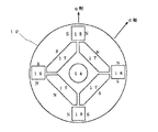
そのため、図1および図2に示すように、この永久磁石電動機のロータコア10は、各磁極を希土類磁石の永久磁石11とフェライト磁石の永久磁石12とで構成し、かつ永久磁石12を隣接磁極の共有にしている。永久磁石11は断面長方形(薄めの板状)をなしてコア内径(中心孔14)の周囲に沿って円周方向に極数(例えば4極)に相当する数だけ配置され、永久磁石12は断面長方形(厚めの板状)をなして永久磁石11による磁極の境界上でコア半径の1/3程度から外径方向に配置されている。したがって、各磁極は永久磁石11と永久磁石12,12の3つで構成される。また、永久磁石11の両端部と永久磁石12のコア内径側端部との間には磁束の短絡、漏洩を防止するためにフラックスバリア用の孔13が設けられている。なお、14はシャフト用の中心孔で、15はステータコアである。
【0013】
図3を参照してリラクタンストルクおよび磁束密度について説明する。なお、図中、破線矢印の曲線は磁束を表している。この場合、各磁極毎に希土類磁石の永久磁石11と、隣接磁極で共有の永久磁石12,12とを配置していることから、磁束密度を大きくすることが可能であり、また図3の破線枠Aに示すように、各磁極のコア外径側ほど広い領域をとることが可能である。したがって、図3に示す破線枠Aを広くとり、つまりこの磁石の占める割合を減らし、電磁鋼板からなるコアの占める割合を増やすことができることから、d軸インダクタンスに比べてq軸インダクタンスが大きくとれ、q軸とd軸インダクタンスの差(リラクタンストルクのパラメータ)が大きくなり、リラクタンストルクが大きくなる。
【0014】
また、フェライト磁石と希土類磁石の併用により磁束密度が抑えられ、例えば全てを希土類磁石で構成した場合と比較して磁束密度が低くなり、つまり磁束密度が高過ぎず、適切な磁束密度を選択することができる。しかも、例えば全てをフェライト磁石で構成する場合、必要とする磁束密度を得ようとすると、永久磁石の厚さ(着磁幅)が製造上の限界を越えることもあるが、フェライト磁石と希土類磁石とを併用することにより磁束密度を調整することができ、つまり着磁幅以外の方法で所望の磁束密度を容易に得ることができる。なお、永久磁石11と永久磁石12との間に設けたフラックスバリア用の孔13により、磁束の短絡、漏洩を防止することができるため、特に永久磁石11による磁束誤差が小さく、つまり必要とする磁束密度をより容易に得ることができる。
【0015】
このように、希土類磁石の永久磁石11によって磁束密度を上げ、あるいは磁束密度を下げ、フェライト磁石の永久磁石12によって磁束密度を微妙に調整することができ、つまり最適な磁束密度を容易に得ることができる。しかも、安価なフェライト磁石を併用することにより希土類磁石の使用量が抑えられ、例えば磁極を全て希土類磁石で構成した場合と比較して安価に済ませることができ、低コスト化を図ることができる。また、前述した理由により、リラクタンストルクおよび磁束密度を選択幅(自由度)の幅を広げることができ、ひいては適応的モータを容易に得ることができる。
【0016】
図2に示すように、ロータコア10にあっては、電磁鋼板をプレスで打ち抜いて金型内で自動積層して得、永久磁石11,12を埋設して着磁するが、そのプレスの際に予め少なくとも永久磁石11,12の形状孔を形成しておく。また、同時にフラックスバリア用の孔13も形成するとよい。したがって、従来の製造工程と変わらず、つまりコスト的には従来と変わらず、コストアップにならずに済む。また、前述により形成されるロータコアを組み込んでブラシレスDCモータとし、空気調和機の圧縮機モータ等として利用すれば、コストをアップすることなく、空気調和機の性能アップ(運転効率の上昇、振動や騒音の低下)が図れる。
【0017】
なお、少なくとも永久磁石11の形状孔およびフラックスバリア用の孔13は一体的、つまり連結した孔にしてもよい。また、永久磁石12のコア外径側の箇所が遠心力に耐えられるように、十分な強度をもたせる。さらに、ステータコア15は図7および図8と同様でよいことから、その説明を省略する。
【0018】
図4は前記実施の形態の変形例である。なお、図中、図3と同一部分には同一符号を付して重複説明を省略する。この永久磁石電動機のロータコア10は、前記実施の形態の永久磁石12を2つに分割した形で、つまり断面長方形(前実施例より薄めの板状)をなすフェライト永久磁石の永久磁石16a,16bを磁極境界に沿ってコア内径の1/3程度から外径方向に配置している。したがって、各磁極は永久磁石11および永久磁石16a,16bの3つで構成される。
【0019】
この場合、永久磁石16a,16bの着磁幅が前実施例(図3参照)より小さくなるが、例えば永久磁石16a,16bを永久磁石12より長く、かつ希土類磁石の永久磁石11の着磁幅を図3より大きくすれば、図3と同程度の磁束密度とすることができる。
したがって、磁束密度については前記実施例と変わらず、またコアの磁石占有率が上がることもなく、つまり図3と同様に永久磁石のない領域を広くとることができることから、d軸インダクタンスに比べてq軸インダクタンスが大きくとれ、q軸とd軸インダクタンスとの差が大きくなり、リラクタンストルクが大きくなる。また、永久磁石16a,16bのコア外径側端部とコア外径との間の箇所における負担が軽くなるため、その箇所の強度が遠心力に十分耐えるようになる。
【0020】
図5は本発明のロータコアの変形例である。なお、図中、図3と同一部分には同一符号を付して重複説明を省略する。この永久磁石電動機のロータコア10は、図3に示す実施例のフェライト磁石と希土類磁石とを逆とし、つまり永久磁石11に代えてフェライト磁石の永久磁石17を配置し、永久磁石12に代えて希土類磁石の永久磁石18を配置している。
【0021】
永久磁石17は断面多角形(例えば変形六角形)をなしてコア内径の周囲に沿って円周方向に極数に相当する数だけ配置されている。この永久磁石17は永久磁石18より小さい分長くし、かつ着磁幅を大きくし、磁束密度を補っている。永久磁石18は断面長方形(厚めの板状)をなして永久磁石17による磁極の境界上でコア半径の2/3程度から外径方向に配置されている。この永久磁石18は永久磁石12より小さいが、希土類磁石であることから、永久磁石12と変わらない磁束密度を発生する。
【0022】
したがって、この変形例のロータコア10にあっては、前記実施例とほぼ同程度の磁束密度を発生することが期待でき、またコアの磁石占有率がそれほど上がることもなく、つまり図3と同程度に永久磁石のない領域を広くとることができることから、d軸インダクタンスに比べてq軸インダクタンスが大きくとれ、q軸とd軸インダクタンスとの差が大きくなり、リラクタンストルクが大きくなる。なお、永久磁石18の端部側にフラックスバリアを設けるようにしてもよいが、永久磁石18のコア外径側端部がコアの外径にできるだけ近づけるようにすれば、フラックスバリアを設けずに済む。
【0023】
図6は図5に示す実施の形態の変形例である。なお、図中、図5と同一部分には同一符号を付して重複説明を省略する。この永久磁石電動機のロータコア10は、前記永久磁石18を2つに分割した形で、つまり断面長方形(薄めの板状)をなす希土類永久磁石の永久磁石19a,19bを磁極境界に沿ってコア内径の2/3程度から外径方向に配置している。したがって、各磁極は永久磁石17および永久磁石19a,19bの3つで構成される。
【0024】
この場合、永久磁石19a,19bの着磁幅が前記実施例(図5参照)より多少小さくなるが、例えば永久磁石19a,19bを大きくし(半径方向に長くし)、かつフェライト磁石の永久磁石17の着磁幅を図5より小さくすれば、図5と同程度の磁束密度とすることができる。したがって、磁束密度については前記実施例と変わらず、またコアの磁石占有率が上がることがあっても、下がることがなく、つまり図3と同様に永久磁石のない領域を広くとることができることから、d軸インダクタンスに比べてq軸インダクタンスが大きくとれ、q軸とd軸インダクタンスとの差が大きくなり、リラクタンストルクが大きくなる。なお、永久磁石19a,19bの端部側にフラックスバリアを設けるようにしてもよいが、永久磁石19a,19bのコア外径側端部がコアの外径に極めて近づけるようにすれば、フラックスバリアを設けずに済み、これによりコア外径側端部のコア強度をより維持することができる。
【0025】
このように、フェライト磁石と希土類磁石とを種々組み合わせることにより、種々なリラクタンストルクおよび磁束密度を選択することができ、つまりそれらの選択度を広げることができる。なお、図4ないし図6に示した実施の形態について、図1ないし図3の実施の形態と同様の効果を奏することは明かである。
【0026】
【発明の効果】
以上説明したように、本発明によれば、ステータコア内に磁石埋込型界磁鉄心(ロータコア)を配置してなる永久磁石電動機において、前記永久磁石電動機の界磁の磁極を構成する磁石には、ロータコア内径の周囲に沿って円周方向に極数に相当する数だけ配置される第1永久磁石と、前記第1永久磁石による磁極の境界に沿って配置される第2永久磁石とが含まれ、前記第2永久磁石を隣接磁極の共有として、前記各磁極が少なくとも3つの永久磁石により構成され、前記第1永久磁石が希土類磁石よりなり、前記第2永久磁石がフェライト磁石からなる構成としたことにより、磁石のない範囲を各磁極のコア外径側ほど広く、d軸インダクタンスに比べてq軸インダクタンスを大きくすることでq軸とd軸インダクタンスの差を大きく、つまり、リラクタンストルクを大きくすることができる。また、フェライト磁石の磁束密度が低いことから、希土類磁石との併用によって磁束密度を調節して適切な磁束密度を得て所望の磁束密度を得易くすることができ、つまり、リラクタンストルクおよび磁束密度の選択幅を広げ、磁束密度の選択幅を広げることができる。しかも安価なフェライト磁石を併用することで、低コスト化を図ることができ、ひいては適応的モータを得ることができるという効果がある。
【図面の簡単な説明】
【図1】 本発明の実施の一形態を示す永久磁石電動機の概略的平面図。
【図2】 図1に示す永久磁石電動機のロータの概略的縦断面図。
【図3】 図1に示す永久磁石電動機のロータの概略的拡大平面図。
【図4】 図1に示す永久磁石電動機のロータの変形例を説明するための概略的平面図。
【図5】 図1に示す永久磁石電動機のロータの変形例を説明するための概略的平面図。
【図6】 図1に示す永久磁石電動機のロータの変形例を説明するための概略的平面図。
【図7】 従来の永久磁石電動機の概略的平面図。
【図8】 従来の永久磁石電動機の概略的平面図。
【符号の説明】
10 ロータコア(磁石埋込型界磁鉄心)
11,18,19a,19b 永久磁石(希土類磁石)
12,16a,16b,17 永久磁石(フェライト磁石)
13 孔(フラックスバリア用)
14 中心孔(シャフト用)
15 ステータコア[0001]
BACKGROUND OF THE INVENTION
The present invention relates to an inner rotor type permanent magnet motor used in the compressor or the like, in particular detail, it relates to adaptive motor can be obtained a permanent magnet motor rotor structure.
[0002]
[Prior art]
The inner rotor configuration of this type of permanent magnet motor has a permanent magnet embedded in the rotor core, and for example, those shown in FIGS. 7 and 8 have been proposed. As shown in FIG. 7, on the
[0003]
Here, assuming that the magnetic flux distribution in the gap (between the teeth of the
[0004]
In the above formula, the first term is the magnet torque generated by the
[0005]
By the way, typical
[0006]
[Problems to be solved by the invention]
However, in the permanent magnet motor, as shown in FIGS. 7 and 8, only one type (for example, one of a rare earth magnet or a ferrite magnet) is used as the permanent magnet constituting the magnetic pole (four poles). There were the following drawbacks.
[0007]
For example, when a permanent magnet of a magnetic pole is composed only of ferrite magnets, the amount of magnets must be increased to increase the magnetic flux density (the magnetization width must be increased), and as a result, most of the rotor core is Thus, the q-axis inductance is small, the difference between the q-axis and the d-axis inductance (reluctance torque parameter; see the above equation) is small, and sufficient reluctance torque cannot be obtained. Also, when the permanent magnet of the magnetic pole is composed of only rare earth magnets, the magnetic flux density is high, so it does not occupy most of the rotor core as in the case of a ferrite magnet, but the magnetic flux density may be too high, Moreover, since it is expensive as mentioned above, the cost of a motor will become high. As described above, it is difficult to obtain a desired reluctance torque and magnetic flux density, that is, it is difficult to obtain a low-cost one corresponding to a narrow selection range and an appropriate motor.
[0008]
The present invention has been made in view of the above-mentioned problems, and its object is to expand the selection range of the reluctance torque and magnetic flux density and to reduce the cost, and to obtain an adaptive motor. It is to provide an electric motor.
[0009]
[Means for Solving the Problems]
In order to achieve the above object, the present invention provides a permanent magnet motor in which a magnet-embedded field core (rotor core) is arranged in a stator core, wherein the magnet constituting the magnetic pole of the field of the permanent magnet motor is a magnet. And a first permanent magnet arranged in a number corresponding to the number of poles in the circumferential direction along the circumference of the rotor core inner diameter, and a second permanent magnet arranged along the boundary of the magnetic poles of the first permanent magnet. The second permanent magnet is shared by adjacent magnetic poles, each magnetic pole is composed of at least three permanent magnets, the first permanent magnet is composed of a rare earth magnet, and the second permanent magnet is composed of a ferrite magnet. It is a feature.
[0010]
In the present invention, the second permanent magnet may include two permanent magnets having a rectangular cross section arranged parallel to each other along the boundary of the magnetic pole.
[0011]
DETAILED DESCRIPTION OF THE INVENTION
Hereinafter, embodiments of the present invention will be described in detail with reference to FIGS. In the permanent magnet motor according to the present invention, if a plurality of permanent magnets for each magnetic pole are formed of different materials, various reluctance torques and magnetic flux densities can be selected, and the cost can be reduced. This is because it does not interfere with the rotation of the motor.
[0012]
Therefore, as shown in FIG. 1 and FIG. 2, the
[0013]
The reluctance torque and the magnetic flux density will be described with reference to FIG. In the figure, the curve of the broken line arrows represent the magnetic flux. In this case, since the permanent magnet 11 of the rare earth magnet and the shared permanent magnets 12 and 12 are arranged for the adjacent magnetic poles for each magnetic pole, the magnetic flux density can be increased, and the breakage of FIG. As shown in the line frame A, it is possible to take a wider area on the core outer diameter side of each magnetic pole. Therefore, taking a wide broken line frame A illustrated in FIG. 3, i.e. reducing the percentage of the magnet, since it is possible to increase the proportion of core made of magnetic steel, q-axis inductance made large as compared with the d-axis inductance The difference between the q-axis and d-axis inductance (reluctance torque parameter) increases, and the reluctance torque increases.
[0014]
In addition, the combined use of ferrite magnets and rare earth magnets reduces the magnetic flux density. For example, the magnetic flux density is lower than when all of the magnets are composed of rare earth magnets. That is, the magnetic flux density is not too high, and an appropriate magnetic flux density is selected. be able to. Moreover, for example, when all of the magnets are composed of ferrite magnets, the thickness (magnetization width) of the permanent magnets may exceed the manufacturing limit if an attempt is made to obtain the required magnetic flux density. In combination, the magnetic flux density can be adjusted, that is, a desired magnetic flux density can be easily obtained by a method other than the magnetization width. In addition, since the
[0015]
In this way, the magnetic flux density can be increased or decreased by the rare-earth magnet permanent magnet 11 and the magnetic flux density can be finely adjusted by the ferrite magnet permanent magnet 12, that is, the optimum magnetic flux density can be easily obtained. Can do. In addition, by using an inexpensive ferrite magnet in combination, the amount of rare earth magnet used can be reduced. For example, it is possible to reduce the cost compared to the case where all the magnetic poles are composed of rare earth magnets, and the cost can be reduced. For the reasons described above, the reluctance torque and magnetic flux density can be selected from a wider range of freedom (degree of freedom), so that an adaptive motor can be easily obtained.
[0016]
As shown in FIG. 2, the
[0017]
At least the shape hole of the permanent magnet 11 and the
[0018]
FIG. 4 shows a modification of the above embodiment. In the figure, the same parts as those in FIG. The
[0019]
In this case, the magnetization width of the permanent magnets 16a and 16b is smaller than that of the previous embodiment (see FIG. 3). For example, the permanent magnets 16a and 16b are longer than the permanent magnet 12 and the magnetization width of the permanent magnet 11 of a rare earth magnet. Is made larger than that in FIG. 3, the magnetic flux density can be made comparable to that in FIG. 3.
Therefore, no change from the previous SL embodiment for the magnetic flux density, also possible without the magnet occupancy of the core increases, i.e. since it is possible to widen the area without the permanent magnets in the same manner as FIG. 3, compared with the d-axis inductance As a result, the q-axis inductance is increased, the difference between the q-axis and the d-axis inductance is increased, and the reluctance torque is increased. Moreover, since the burden in the location between the core outer-diameter side edge part of permanent magnet 16a, 16b and a core outer diameter becomes light, the intensity | strength of the location comes to fully endure centrifugal force.
[0020]
FIG. 5 shows a modification of the rotor core of the present invention. In the figure, the same parts as those in FIG. In the
[0021]
[0022]
Therefore, in the
[0023]
FIG. 6 shows a modification of the embodiment shown in FIG. In the figure, the same parts as those in FIG. The
[0024]
In this case, the permanent magnets 19a, although 19b of magnetization width is slightly smaller than the previous SL embodiment (see FIG. 5), for example, a permanent magnet 19a, 19b and the large (long in the radial direction), and the ferrite magnet permanent If the magnetized width of the
[0025]
As described above, various reluctance torques and magnetic flux densities can be selected by combining various ferrite magnets and rare earth magnets, that is, their selectivity can be expanded. It is obvious that the embodiment shown in FIGS. 4 to 6 has the same effect as the embodiment shown in FIGS.
[0026]
【The invention's effect】
As described above , according to the present invention, in a permanent magnet motor in which a magnet-embedded field core (rotor core) is disposed in a stator core, the magnet constituting the magnetic pole of the field of the permanent magnet motor And a first permanent magnet arranged in a number corresponding to the number of poles in the circumferential direction along the circumference of the rotor core inner diameter, and a second permanent magnet arranged along the boundary of the magnetic poles of the first permanent magnet. The second permanent magnet is shared by adjacent magnetic poles, each magnetic pole is composed of at least three permanent magnets, the first permanent magnet is composed of a rare earth magnet, and the second permanent magnet is composed of a ferrite magnet. by the wider range without the magnet as the core outer diameter side of each magnetic pole, increasing the difference between the q-axis and d-axis inductance by increasing the q-axis inductance as compared to the d-axis inductance, Mari, it is possible to increase the reluctance torque. Moreover, since the magnetic flux density of the ferrite magnet is low, the magnetic flux density can be adjusted in combination with the rare earth magnet to obtain an appropriate magnetic flux density to facilitate obtaining a desired magnetic flux density, that is, reluctance torque and magnetic flux density. Can be expanded, and the selection range of magnetic flux density can be expanded. In addition, by using an inexpensive ferrite magnet in combination, the cost can be reduced, and as a result, an adaptive motor can be obtained.
[Brief description of the drawings]
FIG. 1 is a schematic plan view of a permanent magnet motor showing an embodiment of the present invention.
FIG. 2 is a schematic longitudinal sectional view of a rotor of the permanent magnet motor shown in FIG.
3 is a schematic enlarged plan view of a rotor of the permanent magnet motor shown in FIG. 1. FIG.
4 is a schematic plan view for explaining a modification of the rotor of the permanent magnet motor shown in FIG. 1; FIG.
FIG. 5 is a schematic plan view for explaining a modification of the rotor of the permanent magnet motor shown in FIG. 1;
6 is a schematic plan view for explaining a modified example of the rotor of the permanent magnet motor shown in FIG. 1; FIG.
FIG. 7 is a schematic plan view of a conventional permanent magnet motor.
FIG. 8 is a schematic plan view of a conventional permanent magnet motor.
[Explanation of symbols]
10 Rotor core (embedded magnet field core)
11, 18, 19a, 19b Permanent magnet (rare earth magnet)
12, 16a, 16b, 17 Permanent magnet (ferrite magnet)
13 holes (for flux barrier)
14 Center hole (for shaft)
15 Stator core
Claims (2)
前記永久磁石電動機の界磁の磁極を構成する磁石には、ロータコア内径の周囲に沿って円周方向に極数に相当する数だけ配置される第1永久磁石と、前記第1永久磁石による磁極の境界に沿って配置される第2永久磁石とが含まれ、前記第2永久磁石を隣接磁極の共有として、前記各磁極が少なくとも3つの永久磁石により構成され、前記第1永久磁石が希土類磁石よりなり、前記第2永久磁石がフェライト磁石からなることを特徴とする永久磁石電動機。 In a permanent magnet motor in which a magnet-embedded field core (rotor core) is disposed in a stator core,
The magnets constituting the magnetic poles of the field of the permanent magnet motor include first permanent magnets arranged in a number corresponding to the number of poles in the circumferential direction along the circumference of the inner diameter of the rotor core, and magnetic poles formed by the first permanent magnets. A second permanent magnet disposed along the boundary of the second permanent magnet, wherein the second permanent magnet is shared by adjacent magnetic poles, each magnetic pole is composed of at least three permanent magnets, and the first permanent magnet is a rare earth magnet. And the second permanent magnet is a ferrite magnet .
Priority Applications (1)
| Application Number | Priority Date | Filing Date | Title |
|---|---|---|---|
| JP28910297A JP3832530B2 (en) | 1997-10-06 | 1997-10-06 | Permanent magnet motor |
Applications Claiming Priority (1)
| Application Number | Priority Date | Filing Date | Title |
|---|---|---|---|
| JP28910297A JP3832530B2 (en) | 1997-10-06 | 1997-10-06 | Permanent magnet motor |
Publications (2)
| Publication Number | Publication Date |
|---|---|
| JPH11113199A JPH11113199A (en) | 1999-04-23 |
| JP3832530B2 true JP3832530B2 (en) | 2006-10-11 |
Family
ID=17738826
Family Applications (1)
| Application Number | Title | Priority Date | Filing Date |
|---|---|---|---|
| JP28910297A Expired - Fee Related JP3832530B2 (en) | 1997-10-06 | 1997-10-06 | Permanent magnet motor |
Country Status (1)
| Country | Link |
|---|---|
| JP (1) | JP3832530B2 (en) |
Cited By (3)
| Publication number | Priority date | Publication date | Assignee | Title |
|---|---|---|---|---|
| WO2013114541A1 (en) * | 2012-01-30 | 2013-08-08 | 三菱電機株式会社 | Embedded permanent magnet electric motor and compressor |
| JP2014192907A (en) * | 2013-03-26 | 2014-10-06 | Meidensha Corp | Embedded magnet motor |
| JP5619305B2 (en) * | 2012-01-30 | 2014-11-05 | 三菱電機株式会社 | Permanent magnet embedded electric motor and compressor |
Families Citing this family (15)
| Publication number | Priority date | Publication date | Assignee | Title |
|---|---|---|---|---|
| JP2001211582A (en) * | 2000-01-26 | 2001-08-03 | Fujitsu General Ltd | Permanent magnet motor |
| JP2002084722A (en) * | 2000-09-06 | 2002-03-22 | Fujitsu General Ltd | Permanent magnet motor |
| JP3835231B2 (en) * | 2001-10-04 | 2006-10-18 | 松下電器産業株式会社 | Electric motor |
| US9472986B2 (en) | 2011-12-26 | 2016-10-18 | Mitsubishi Electric Corporation | Rotor |
| JP6055189B2 (en) * | 2012-03-01 | 2016-12-27 | 株式会社日立産機システム | Permanent magnet rotating electric machine |
| CN203166649U (en) * | 2012-07-25 | 2013-08-28 | 艾默生环境优化技术(苏州)有限公司 | Hybrid permanent magnet rotor assembly and corresponding motor |
| KR20190018046A (en) | 2012-09-29 | 2019-02-20 | 에머슨 일렉트릭 컴파니 | Rotors with segmented magnet configurations and related dynamoelectric machines and compressors |
| DE112014000526B4 (en) * | 2013-01-23 | 2018-03-01 | Mitsubishi Electric Corporation | Rotor and rotating electrical machine containing this rotor |
| JP2015186383A (en) * | 2014-03-25 | 2015-10-22 | アイシン・エィ・ダブリュ株式会社 | Rotating electrical machine rotor |
| CN104806540A (en) * | 2015-04-06 | 2015-07-29 | 叶露微 | Small-power ventilation fan directly driven by permanent magnet motor |
| US10581287B2 (en) | 2018-01-02 | 2020-03-03 | GM Global Technology Operations LLC | Permanent magnet electric machine with variable magnet orientation |
| CN110048531A (en) * | 2019-04-23 | 2019-07-23 | 山东理工大学 | Tangential Radial Combinations permanent magnetism and electromagnetic hybrid excitation driving motor |
| WO2021217671A1 (en) | 2020-04-30 | 2021-11-04 | 华为技术有限公司 | Rotor, permanent magnet motor, motor driving system and vehicle |
| CN114123580B (en) * | 2021-11-16 | 2023-02-28 | 珠海格力电器股份有限公司 | Self-starting permanent magnet auxiliary synchronous reluctance motor rotor and motor |
| CN114400855B (en) * | 2022-01-24 | 2023-06-16 | 沈阳工程学院 | Stator-rotor double-module permanent magnet synchronous motor |
-
1997
- 1997-10-06 JP JP28910297A patent/JP3832530B2/en not_active Expired - Fee Related
Cited By (3)
| Publication number | Priority date | Publication date | Assignee | Title |
|---|---|---|---|---|
| WO2013114541A1 (en) * | 2012-01-30 | 2013-08-08 | 三菱電機株式会社 | Embedded permanent magnet electric motor and compressor |
| JP5619305B2 (en) * | 2012-01-30 | 2014-11-05 | 三菱電機株式会社 | Permanent magnet embedded electric motor and compressor |
| JP2014192907A (en) * | 2013-03-26 | 2014-10-06 | Meidensha Corp | Embedded magnet motor |
Also Published As
| Publication number | Publication date |
|---|---|
| JPH11113199A (en) | 1999-04-23 |
Similar Documents
| Publication | Publication Date | Title |
|---|---|---|
| JP3818340B2 (en) | Permanent magnet motor | |
| US6025667A (en) | Permanent magnet rotor type electric motor with different permanent magnet materials | |
| JP2002084722A (en) | Permanent magnet motor | |
| JP3821183B2 (en) | Permanent magnet motor | |
| JP2002136011A (en) | Permanent magnet motor | |
| JPH11113199A (en) | Permanent magnet motor | |
| JPH11243653A (en) | Permanent magnet motor | |
| JP2000333389A (en) | Permanent magnet motor | |
| JPH11113198A (en) | Permanent magnet motor | |
| JP2000278896A (en) | Motor rotor | |
| JP2001095182A (en) | Permanent magnet motor | |
| JP3818341B2 (en) | Permanent magnet motor | |
| JP3832535B2 (en) | Permanent magnet motor | |
| JPH1189133A (en) | Permanent magnet type motor | |
| WO2002027893A1 (en) | Rotor of electric motor | |
| JP2001211582A (en) | Permanent magnet motor | |
| JP3818339B2 (en) | Permanent magnet motor | |
| JP2000245087A (en) | Permanent magnet motor | |
| JP2001086673A (en) | Permanent magnet motor | |
| JP4080273B2 (en) | Permanent magnet embedded motor | |
| JPH1189134A (en) | Permanent magnet type motor | |
| JP2000333390A (en) | Permanent magnet motor | |
| JP3821185B2 (en) | Permanent magnet motor | |
| JP3832540B2 (en) | Permanent magnet motor | |
| JP3821184B2 (en) | Permanent magnet motor |
Legal Events
| Date | Code | Title | Description |
|---|---|---|---|
| A977 | Report on retrieval |
Free format text: JAPANESE INTERMEDIATE CODE: A971007 Effective date: 20051031 |
|
| A131 | Notification of reasons for refusal |
Free format text: JAPANESE INTERMEDIATE CODE: A131 Effective date: 20051109 |
|
| A602 | Written permission of extension of time |
Free format text: JAPANESE INTERMEDIATE CODE: A602 Effective date: 20060124 |
|
| A521 | Written amendment |
Free format text: JAPANESE INTERMEDIATE CODE: A523 Effective date: 20060216 |
|
| A131 | Notification of reasons for refusal |
Free format text: JAPANESE INTERMEDIATE CODE: A131 Effective date: 20060524 |
|
| A521 | Written amendment |
Free format text: JAPANESE INTERMEDIATE CODE: A523 Effective date: 20060525 |
|
| TRDD | Decision of grant or rejection written | ||
| A01 | Written decision to grant a patent or to grant a registration (utility model) |
Free format text: JAPANESE INTERMEDIATE CODE: A01 Effective date: 20060628 |
|
| A61 | First payment of annual fees (during grant procedure) |
Free format text: JAPANESE INTERMEDIATE CODE: A61 Effective date: 20060711 |
|
| FPAY | Renewal fee payment (event date is renewal date of database) |
Free format text: PAYMENT UNTIL: 20090728 Year of fee payment: 3 |
|
| FPAY | Renewal fee payment (event date is renewal date of database) |
Free format text: PAYMENT UNTIL: 20100728 Year of fee payment: 4 |
|
| FPAY | Renewal fee payment (event date is renewal date of database) |
Free format text: PAYMENT UNTIL: 20110728 Year of fee payment: 5 |
|
| FPAY | Renewal fee payment (event date is renewal date of database) |
Free format text: PAYMENT UNTIL: 20110728 Year of fee payment: 5 |
|
| FPAY | Renewal fee payment (event date is renewal date of database) |
Free format text: PAYMENT UNTIL: 20120728 Year of fee payment: 6 |
|
| FPAY | Renewal fee payment (event date is renewal date of database) |
Free format text: PAYMENT UNTIL: 20130728 Year of fee payment: 7 |
|
| LAPS | Cancellation because of no payment of annual fees |