JP3945112B2 - Impact rotary tool - Google Patents
Impact rotary tool Download PDFInfo
- Publication number
- JP3945112B2 JP3945112B2 JP2000028446A JP2000028446A JP3945112B2 JP 3945112 B2 JP3945112 B2 JP 3945112B2 JP 2000028446 A JP2000028446 A JP 2000028446A JP 2000028446 A JP2000028446 A JP 2000028446A JP 3945112 B2 JP3945112 B2 JP 3945112B2
- Authority
- JP
- Japan
- Prior art keywords
- detection signal
- circuit
- detection
- impact
- output
- Prior art date
- Legal status (The legal status is an assumption and is not a legal conclusion. Google has not performed a legal analysis and makes no representation as to the accuracy of the status listed.)
- Expired - Fee Related
Links
- 238000001514 detection method Methods 0.000 claims description 176
- 238000000034 method Methods 0.000 claims description 3
- 238000010586 diagram Methods 0.000 description 22
- 239000003990 capacitor Substances 0.000 description 19
- 230000000694 effects Effects 0.000 description 11
- 239000000428 dust Substances 0.000 description 2
- 239000010687 lubricating oil Substances 0.000 description 2
- 239000000284 extract Substances 0.000 description 1
- 238000004519 manufacturing process Methods 0.000 description 1
- 230000013011 mating Effects 0.000 description 1
- 230000003287 optical effect Effects 0.000 description 1
- 230000002093 peripheral effect Effects 0.000 description 1
- 230000000630 rising effect Effects 0.000 description 1
Images









Landscapes
- Details Of Spanners, Wrenches, And Screw Drivers And Accessories (AREA)
Description
【0001】
【発明の属する技術分野】
本発明は、ボルトやナット等のねじの締め付け作業及び緩め作業に使用するインパクトレンチやインパクトドライバのようなインパクト回転工具に関するものである。
【0002】
【従来の技術】
インパクト回転工具は、回転駆動されるハンマによる打撃衝撃を出力軸に加えることで出力軸を回転させてボルトやナット等のねじの締め付け作業や緩め作業を行うものである。このようなインパクト回転工具は、モータの減速出力で出力軸を直接回転させる回転工具に比べて、高い締付トルクを得られるが、その反面、小径のボルトやナットを締め付ける際は、締めすぎて破損させてしまう場合があり、それを恐れた場合は内部に備えられたモータの回転を早めに停止していまい、締付トルクが不足することになる。上述のような締め付けすぎによる破損ならびに締付トルク不足を避けるために、従来のインパクト回転工具では予め所定のトルク設定を行うと共に、例えば図21に示すように、モータ1を囲むハウジング1aにマイク5aを取り付け、ハンマによる打撃音を電気信号に変換し、マイク5aに接続した処理回路13により打撃音をカウントし、所定の回数に達するとモータを停止させるようにしている。
【0003】
【発明が解決しようとする課題】
しかしながら、締め付ける相手部材が軟質であれば打撃音が小さく、その打撃音をマイク5aで検知できないといった問題があった。
【0004】
本発明は上記問題点の解決を目的とするものであり、打撃を確実に検知することによって締付トルク精度を向上させたインパクト回転工具を提供する。
【0005】
【課題を解決するための手段】
上記目的を達成するために、請求項1の発明は、モータで回転駆動されるハンマによる出力軸の打撃によって出力軸に回転力を加えるインパクト回転工具において、ハンマの打撃によって生じる互いに異なる複数種の変動を、それぞれ各種別に検知して検知信号を出力する複数の検知手段と、複数の検知手段の検知信号から各別に打撃を判別し、打撃検知信号を出力する処理回路と、複数の検知手段の少なくとも1つからの検知信号により打撃と判別されたとき、打撃回数をカウントし、打撃回数が所定の回数に達するとモータを停止させる制御手段とを備えたことを特徴とし、複数種であるから従来例のように1種類の検知手段と処理回路による打撃の誤検知を防止し、打撃を正確に検知して、締付トルク精度を向上させることができる。
【0006】
請求項2の発明は、請求項1の発明において、モータに電力を供給する電池を備え、複数の検知手段は、電池の両端電圧の変動を検知して検知信号を出力する電池電圧検知回路と、モータの回転数に略比例した振幅の検知信号を出力する周波数ジェネレータとであることを特徴とし、請求項1の発明と同様の作用を奏する。
【0007】
請求項3の発明は、請求項1の発明において、モータに電力を供給する電池を備え、複数の検知手段は、電池の両端電圧の変動を検知して検知信号を出力する電池電圧検知回路と、ハンマによる打撃音を検知して検知信号を出力するマイクとであることを特徴とし、請求項1の発明と同様の作用を奏する。
【0008】
請求項4の発明は、請求項1の発明において、複数の検知手段は、モータの回転数に略比例した振幅の検知信号を出力する周波数ジェネレータと、ハンマによる打撃音を検知して検知信号を出力するマイクであることを特徴とし、請求項1の発明と同様の作用を奏する。
【0009】
請求項5の発明は、請求項1の発明において、モータに電力を供給する電池を備え、複数の検知手段は、モータの回転数に略比例した振幅の検知信号を出力する周波数ジェネレータと、電池の両端電圧の変動を検知して検知信号を出力する電池電圧検知回路と、ハンマによる打撃音を検知して検知信号を出力するマイクとであり、周波数ジェネレータからの検知信号と、マイク又は電池電力検知回路の少なくとも何れか一方からの検知信号とから処理回路で打撃を略同時に判別したときに、制御回路は打撃回数をカウントすることを特徴とし、請求項1の発明と同様の作用を奏する。
【0010】
請求項6の発明は、請求項1記載の発明において、スイッチング素子を備えてモータを駆動させる駆動回路と、駆動回路をPWM制御するPWM回路とを備え、複数の検知手段のうち少なくとも1つは、モータの回転数に略比例した周波数の検知信号を出力するパルスジェネレータであることを特徴とし、検知手段をパルスジェネレータとしたことによって、PWM制御信号に起因する検知信号波形の歪の発生を防止し、打撃をさらに確実に検知し、締付トルク精度をさらに向上させることができる。
【0011】
請求項7の発明は、請求項6記載の発明において、処理回路は、パルスジェネレータから出力される検知信号を、検知信号の周波数に略比例した電圧値に変換するコンバータ回路と、変換された電圧値を基準電圧値と比較して打撃を判別する比較回路とを備えたことを特徴とし、検知信号の周波数に略比例した電圧値を基準電圧値と比較することによって、打撃をさらに確実に検知し、締付トルク精度をさらに向上させることができる。
【0012】
請求項8の発明は、請求項2又は4又は5の何れかに記載の発明において、処理回路は、周波数ジェネレータから出力される検知信号のピーク値を検知するピークホールド回路と、検知信号のピーク値を基準電圧値と比較して打撃を判別する比較回路とを備えたことを特徴とし、検知信号のピーク値を基準電圧値と比較することによって、打撃をさらに確実に検知し、締付トルク精度をさらに向上させることができる。
【0013】
【発明の実施の形態】
(実施形態1)
本実施形態のインパクト回転工具は、図1に示すように、内部に備えた電池6と、電池6から供給される電力によってハンマを回転させるモータ1と、スイッチング素子たるFETを備えてモータ1への供給電力を可変しモータ1を駆動する駆動回路2と、駆動回路2をPWM制御するPWM回路3と、PWM回路3にモータ1の回転数を制御する信号を出力する制御手段たるマイクロコンピュータ(以下「マイコン」と略す)4と、ハンマによる打撃によって生じる互いに異なっる複数種の変動を、それぞれ各種別に検知して打撃検知信号をマイコン4に出力する打撃検知回路5と、PWM回路3及びマイコン4並びに打撃検知回路5のそれぞれに応じた電源を、電池6を電源として作成しそれぞれに供給する電源回路7とを備えている。
【0014】
打撃検知回路5は、ハンマによる打撃音を検知して検知信号を出力するマイク5a、モータ1の回転数に略比例した振幅の検知信号を発生する周波数ジェネレータ5b、電池6の両端電圧の変動を検出して検知信号を出力する電池電圧検知回路5cからなる3つの検知手段と、それぞれから出力される検知信号を各別に処理する検知ブロック5dとを備えている。
【0015】
マイク5aは、従来例に示すように、モータ1を囲むハウジング1aに取り付けられ、マイク5aから出力される検知信号は、検知ブロック5d内部にあるマイク用の処理回路5d1に入力される。処理回路5d1は、検知信号の電圧値と基準電圧値とを比較し、検知信号の電圧値が基準電圧値よりも大きいとき、打撃があったと判断し、矩形波の打撃検知信号をマイコン4の入力端Pに出力するようにしている。
【0016】
マイク用の処理回路5d1は、図2に示すように、マイコン4の入力端Pに出力端子が接続され、マイコン4の出力端DAの基準電圧が反転入力端子に印加されるコンパレータCo1と、コンパレータCo1の反転入力端子に一端を接続されるコンデンサC2と、コンパレータCo1の非反転入力端子に接続されるコンデンサC1と、一端に動作電圧Vdが印加される抵抗R2と、抵抗R2の他端及びコンデンサC1の他端にソースが接続されるトランジスタTr1と、トランジスタTr1のドレインに一端を接続され、他端をコンデンサC2に接続される抵抗3と、抵抗R3及びトランジスタTr1のゲートに接続される抵抗R1と、抵抗R2の直流電圧Vdが印加される一端及びコンパレータCo1の出力端子に接続される抵抗R6と、抵抗R2及びコンデンサC1の直列回路に並列接続されるダイオードD1並びに抵抗R4と、コンデンサC1及びトランジスタTr1並びに抵抗R3の直列回路に並列接続されるダイオードDr2並びに抵抗R5とから成り、マイク5aはこのマイク用の処理回路5d1の抵抗R1に並列接続される。
【0017】
打撃音は、マイク5aによって電圧信号に変換され、マイク用の処理回路5d1のトランジスタTr1を介して増幅されてコンパレータCo1の非反転入力端に入力する。この非反転入力端に入力する電圧信号は、例えば図3に示すような波形を有し、約30m秒毎(約33.3Hz)の打撃音によって時刻t1〜t7の各々の付近には、他の時刻tと比べて大きな振幅を示す波形が現れている。処理回路5d1は、コンパレータCo1で、上述の非反転入力端に入力された電圧信号をマイコン4の基準電圧と比較し、振幅Wより大きな電圧信号であれば打撃があったと判断し、矩形波の打撃検知信号をマイコン4の入力端Pに出力する。マイコン4は、時刻t1〜t7の各々の付近でハンマによる打撃があったとして打撃回数をカウントし処理することができる。
【0018】
ところで、マイク5aによる打撃音の検知では、時刻t2,t3付近での波形の振幅が振幅Wよりも小さいために、処理回路5d1では打撃がなかったものとして誤って判断されることがある。このような誤った判断は、周波数ジェネレータ5b及び電池電圧検知回路5c並びに検知ブロック5dによって防ぐことができる。以下、周波数ジェネレータ及び電池電圧検知回路5cについて詳細に説明する。
【0019】
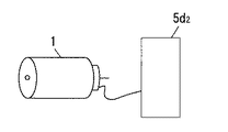
周波数ジェネレータ5bは、図4に示すように、モータ1に設けられ、周波数ジェネレータ5bから出力されるモータ1の回転数に略比例した振幅の検知信号は、処理回路5d内部にある周波数ジェネレータ用の処理回路5d2に入力される。
【0020】
周波数ジェネレータ用の処理回路5d2は、図5に示すように、マイコン4の入力端Pに出力端子が接続されるコンパレータCo2と、コンパレータCo2の反転入力端子に接続されるコンデンサC3及び抵抗R7の直列回路と、コンパレータCo2の非反転入力端子に接続される抵抗R8,R9の直列回路と、コンパレータCoの出力端子および反転入力端子に接続される抵抗R10,R11の直列回路と、コンパレータCoの出力端子および非反転入力端子に接続される抵抗R12と、抵抗R9の抵抗R8が接続されていない一端およびコンパレータCoの反転入力端子に接続される抵抗R13及びダイオードD3並びにコンデンサC4と、抵抗R11に並列接続されるダイオードD4と、抵抗R8,R9の接続点および抵抗R10,R11の接続点に接続される抵抗R14とから成る。そして周波数ジェネレータ5dは、抵抗R7のコンデンサC3に接続されていない一端と抵抗R9,R13の接続点とに接続される。
【0021】
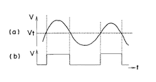
この処理回路5d2は、図6(a)に示すように、振幅Vt以上の検知信号が周波数ジェネレータ5dから入力されると、ハンマによる打撃があったと判断し、図6(b)に示すように、コンパレータCo2の出力端子からマイコン4の入力端Pに矩形波の打撃検知信号を出力する。
【0022】
電池電圧検知回路5cは、図7に示すうに、電池6の両端に接続され、電池6の両端電圧Vを常時計測する。
【0023】
例えば図8に示すように、電池電圧検知回路5cから出力される検知信号の波形は、時刻t8〜t9付近でハンマが略周期的に打撃しているとき、電池6の両端電圧Vの値は略周期的に急激に大きくなる。このような急激に立上がるパルス波形は、ハンマの打撃によって生じるものである。
【0024】
検知ブロック5dは、例えばマイク用の処理回路5d1と同様の電池電圧検知回路用の処理回路を備え、この処理回路に設定された振幅より大きな振幅を有する検知信号が入力されると、矩形波の打撃検知信号をマイコン4の入力端Pに出力する。
【0025】
上述のように、マイコン4の入力端Pには、検知ブロック5dに備えられたマイク用の処理回路5d1及び周波数ジェネレータ用の処理回路5d2ならびに電池電圧検知回路用の処理回路の夫々でハンマによる打撃があったと判断されて出力される矩形波の検知信号が入力されるようにしている。マイコン4は、周波数ジェネレータ用の処理回路5d2又はマイク用の処理回路5d1又は電池電圧検知回路用の処理回路の何れかの検知信号が入力されたとき、ハンマによる打撃があったものと判断し、打撃回数をカウントする。そして、マイコン4は、一定時間内の打撃回数の変化を算出し、打撃回数の変化が所定値よりも大きいとき、PWM回路3にモータ1の回転数を制御する信号を出力する。
【0026】
本実施形態では、互いに異なる3つの検知手段と夫々に対応した処理回路を備えて、そのうちの少なくとも1つの検知信号によって打撃を判別するようにしたことによって、打撃検知を正確にしてトルク管理することができ、締付トルク精度を向上させることができる。
【0027】
ところで、周波数ジェネレータ用の処理回路5d2からの検知信号と、マイク用の処理回路5d1又は電池電圧検知回路用の処理回路の何れか一方からの検知信号とが、略同時にマイコン4に入力したとき、総合的にハンマによる打撃があったものと判断し、打撃回数をカウントしても良い。
【0028】
さらに、マイク5a,周波数ジェネレータ5b,電池電圧検知回路5cの何れか2つと、夫々の検知手段に対応する処理回路とを備えて、マイコン4は、何れか一方の処理回路から打撃検知信号がマイコン4に出力されたとき、ハンマによる打撃があったとして判断し、打撃回数をカウントするようにしても良い。また、電池電圧検知回路5cの代わりに、電池6からモータ1に流す電流値の変動を検知して検知信号を出力する電流検出回路を備えても良い。
【0029】
なお、マイク5aの取付作業は取付精度を要求されるため、本工具の製造が困難となり、さらに取り付けられたマイク5aは、モータ1の回転機構の潤滑油や粉塵の影響を受けてしまう。そこでマイク5aを用いずに、周波数ジェネレータ5bと電池電圧検知回路5cを用いたときには、本工具を容易に製造することができるとともに、潤滑油や粉塵の影響を受けない場所に設置することができる。(実施形態2)
本実施形態は、周波数ジェネレータ用の処理回路5d2に特徴があり、それ以外の構成は実施形態1と共通するので、共通する部分については同一の符号を付して説明を省略する。
【0030】
本実施形態の処理回路5d2は、図9に示すように、周波数ジェネレータ5bから出力される検知信号の電圧のピーク値を保持するピークホールド回路5eと、ピークホールド回路5eによって保持されたピーク値を基準電圧値と比較し、ピーク値が基準電圧値より小さいとき、矩形波の打撃検知信号を出力する比較回路5fとを備えている。
【0031】
ピークホールド回路5eは、図10に示すように、周波数ジェネレータ5bからの検知信号が入力される入力端I1にアノードが接続されるダイオードD5と、ダイオードD5のカソードに非反転入力端子が接続されるオペアンプA1と、入力端I1及びオペアンプA1の出力端子に接続されるダイオードD6及び抵抗R15の直列回路と、ダイオードD5及びオペアンプA1の接続点に一端が接続され、他端側が接地されたコンデンサC4ならびに抵抗R16及びスイッチSWの直列回路とから成る。なお、ダイオードD6及び抵抗R15の直列回路により、ダイオードD5の逆方向のリーク電流を減少させ、オペアンプA1の出力応答時間の改善を図っている。
【0032】
比較回路5fは、オペアンプA1の出力端子に反転入力端子が接続されるコンパレータCo3と、コンパレータCo3の非反転入力端子に正極が接続され、負極を接地した基準電源E1とを備えている。
【0033】
このような処理回路5d2では、周波数ジェネレータ5bのモータ1の回転速度に応じて出力される検知信号の波形の振幅が常に変化することを利用している。例えば、予めピークホールド回路5のスイッチSWをオフにしておき、図11に示すような波形の検知信号が周波数ジェネレータ5bから出力され入力端I1に入力されると、ピークホールド回路5は、時刻t10付近でピークとなる電圧値Vp1に応じた電荷を保持し、電圧値Vp1に応じた電圧信号を比較回路5fのコンパレータCo3に出力する。そして、ピークホールド回路5のスイッチSWは、マイコン4の制御によってオンされ、ピークホールド回路5が保持していた電荷をリセットし、その後再びオフされる。このように、スイッチSWは定期的にオン/オフされて、ピークホールド回路5で保持している電荷を引き抜くようにしているので、次に時刻t11付近でピークとなる電圧値Vp2を有する検知信号が入力されても、同様の動作を繰り返す。
【0034】
コンパレータCo3は、オペアンプA1の出力端子から出力される電圧値Vp1,Vp2に対応する電圧信号を入力し、電圧信号の電圧値を基準電源E1の基準電圧値と比較し、基準電圧値よりも小さいとき、矩形波の打撃検知信号を出力端O1から出力するようにしている。このように基準電圧値と比較して打撃を判別することにより、打撃検知をさらに正確にして、締付トルク精度をさらに向上させることができる。
(実施形態3)
本実施形態は、周波数ジェネレータ5bと処理回路5d2の代わりに、光学的エンコーダであるパルスジェネレータ8とパルスジェネレータ用の処理回路8aを用いた点に特徴があり、それ以外の構成は実施形態1と共通するので、共通する部分については同一の符号を付して説明を省略する。
【0035】
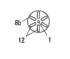
パルスジェネレータ8は、図12及び図13に示すように、略中央部に形成された貫通穴11にモータ1の回転軸1bを通して取り付けられ、略等間隔に配置される複数のスリット12が周部に形成された略円盤状の検出盤8bと、検出盤8bのスリット12が形成された部位を挟むように配置されたフォトインタラプタ8cとを備えている。
【0036】
フォトインタラプタ8cは、図14に示すように、互いに略対向して配置された発光ダイオードD7とフォトトランジスタTr2とを備えて、フォトトランジスタTr2は、発光ダイオードD7からの光を受光したとき、コレクタ−エミッタ間を導通させる。
【0037】
処理回路8aは、マイコン4の入力端Pに出力端子が接続されるコンパレータCo4と、コンパレータCo4の反転入力端子及びフォトトランジスタTr2のコレクタに接続される抵抗R17と、コンパレータCo4の非反転入力端子及びフォトトランジスタTr2のコレクタに接続される抵抗R18、R19,R20の直列回路と、コンパレータCo4の出力端子及びフォトトランジスタTr2のコレクタに接続される抵抗R21と、フォトトランジスタTr2及び抵抗R17の直列回路に並列接続されるダイオードD8と、抵抗R17,R20の直列回路に並列接続されるダイオードD9と、抵抗R18,R19の接続点及びフォトトランジスタTr2のコレクタに接続される抵抗R22と、抵抗R19,R20の接続点及び発光ダイオードD7のカソードに接続される抵抗R23とを備えて、発光ダイオードD7のアノードはフォトトランジスタTr2のコレクタに接続される。
【0038】
上述のようなパルスジェネレータ8と処理回路8aを用いることにより、モータ1の回転軸1bの回転とともに検出盤8bが回転し、検出盤8bのスリット12がフォトトランジスタTr2に略対向したとき、発光ダイオードD7から発する光は、スリット12を通ってフォトトランジスタTr2に受光される。このとき、フォトトランジスタTr2のコレクタ−エミッタ間が導通し、回転軸1bが略一定の速度で回転している場合、コンパレータCo4の出力端子からは、図15に示すような、略一定周期の矩形波の検知信号が出力される。
【0039】
例えば、図16(a)に示すように打撃がない場合、回転軸1bは、フル・スロットル(PWM制御なしの状態)のとき約18000rpmの回転数で回転し、矩形波間の時間差tw1は約170〜195μ秒となる。一方、図16(b)に示すように打撃がある場合、回転軸1bは、フル・スロットルのとき約11000rpmの回転数で回転し、矩形波間の時間差tw2は約290〜340μ秒となる。なお、図16(a),(b)のそれぞれの波形のDuty比は、例えば約36〜38%としている。このように、打撃があった場合と無かった場合とで、矩形波間の時間差tw1,tw2が異なって、一定時間内に出力される矩形波の数が異なる。マイコン4は、この一定時間内の矩形波をカウントすることによって、カウント数が少なければ打撃があったと検知することができる。
【0040】
ところで、PWM回路3からは、駆動回路2のFETを任意のオンデューティでオン/オフするPWM制御信号が出力される。実施形態1及び2では、例えば図17(b)に示すように、時刻t12〜t13付近の間と、時刻t14〜t15付近の間にPWM制御信号が出力されたとき、図17(a)に示すように、周波数ジェネレータ5bから出力される検知信号の波形には歪が発生してしまう。
【0041】
一方、本実施形態では、パルスジェネレータ8から出力される検知信号のPWM制御信号による歪は抑えられ、打撃検知をさらに正確にして締付トルク制度を向上させることができる。
(実施形態4)
本実施形態では、パルスジェネレータ用の処理回路8aに特徴があり、それ以外の構成は実施形態3と共通するので、共通する部分については同一の符号を付して説明を省略する。
【0042】
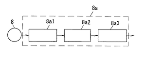
本実施形態の処理回路8aは、図18に示すように、パルスジェネレータ8から出力される検知信号を入力し、この検知信号の周波数を電圧値に変換するF/Vコンバータ回路8a1と、必要な周波数帯域のみを取り出すバンドパスフィルタ回路8a2と、バンドパスフィルタ回路8a2から出力される電圧信号の電圧値を基準電圧値と比較し、基準電圧値よりも小さいとき、矩形波の打撃検知信号を出力する比較回路8a3とを備えている。
【0043】
F/Vコンバータ回路8a1は、図19に示すように、オペアンプA2と、パルスジェネレータ8からの信号を入力する入力端I2及びオペアンプA2の反転入力端子に接続される抵抗24及びコンデンサC6並びにダイオードD10の直列回路と、オペアンプA2の反転入力端子と出力端子に接続される抵抗R25並びにコンデンサC7と、コンデンサC6及びダイオードD10の接続点にアノードが接続され、カソードが接地されたダイオードD11とからなり、オペアンプA2の非反転入力端子は接地されている。このF/Vコンバータ回路8a1の入力端I2には、図20に示すように、パルスジェネレータ8から出力される電圧値Vsの検知信号が入力される。この検知信号のパルスは積分され、コンデンサC7に、コンデンサC6の容量値C6nと電圧値Vsとを乗算した電荷Qが蓄積される。その結果、検知信号の周波数に略比例した電圧値を有する電圧信号がオペアンプA1の出力端子から出力される。
【0044】
バンドパスフィルタ回路8a2は、オペアンプA3と、F/Vコンバータ回路8a1のオペアンプA2の出力端子及びオペアンプA3の非反転入力端子に接続される抵抗R26及びコンデンサC8の直列回路と、抵抗R26及びコンデンサC8の接続点に一端が接続され、他端がオペアンプA3の出力端子に接続された抵抗R27と、コンデンサC8及びオペアンプA3の非反転入力端子の接続点に一端が接続され、他端が接地されたコンデンサC9並びに抵抗28とから成り、オペアンプA3の反転入力端子は出力端子に接続されている。
【0045】
このバンドパスフィルタ回路8a2は、オペアンプA3及びコンデンサC8,C9並びに抵抗R26,R27,R28を用いることにより、反転増幅器による多重帰還タイプに構成され、中心周波数並びにバンド幅を設定することにより、F/Vコンバータ回路8a1から出力される電圧信号の必要とする周波数帯域の電圧信号をオペアンプA3の出力端子から出力させることができる。例えば、マイク用の処理回路5d1から出力される打撃音の周波数から、中心周波数を約33.3Hz、バンド幅を約20〜50Hzとして、その間の周波数の電圧信号を出力させることにより、打撃検知をより正確に検知することができる。また、PWM回路3から出力されるPWM制御信号の影響を受けない周波数帯域の電圧信号を出力させたときには、打撃検知をさらに正確にして、締付トルク精度を向上させることができる。
【0046】
比較回路8a3は、バンドパスフィルタ回路8a2のオペアンプA3の出力端子を反転入力端子に接続するコンパレータCo5と、コンパレータCo5の非反転入力端子に正極を接続し、負極を接地する基準電源E2とから成る。バンドパスフィルタ回路8aを通して出力された電圧信号の電圧値は、コンパレータCo5により基準電源E2の基準電圧値と比較され、基準電圧値より小さいとき、打撃があったとして判断し、矩形波の電圧信号をマイコン4の入力端Pに出力する。
【0047】
ところで、パルスジェネレータ8の代わりに、周波数ジェネレータ5bを用いても良い。さらに、電池電圧検知回路用の処理回路に、バンドパスフィルタ回路8a2を備えても良い。
【0048】
【発明の効果】
請求項1の発明は、モータで回転駆動されるハンマによる出力軸の打撃によって出力軸に回転力を加えるインパクト回転工具において、ハンマの打撃によって生じる互いに異なる複数種の変動を、それぞれ各種別に検知して検知信号を出力する複数の検知手段と、複数の検知手段の検知信号から各別に打撃を判別し、打撃検知信号を出力する処理回路と、複数の検知手段の少なくとも1つからの検知信号により打撃と判別されたとき、打撃回数をカウントし、打撃回数が所定の回数に達するとモータを停止させる制御手段とを備えたので、複数種であるから従来例のように1種類の検知手段と処理回路による打撃の誤検知を防止し、打撃を正確に検知して、締付トルク精度を向上させることができるという効果がある。
【0049】
請求項2の発明は、モータに電力を供給する電池を備え、複数の検知手段は、電池の両端電圧の変動を検知して検知信号を出力する電池電圧検知回路と、モータの回転数に略比例した振幅の検知信号を出力する周波数ジェネレータとであるので、請求項1の発明と同様の効果を奏する。
【0050】
請求項3の発明は、モータに電力を供給する電池を備え、複数の検知手段は、電池の両端電圧の変動を検知して検知信号を出力する電池電圧検知回路と、ハンマによる打撃音を検知して検知信号を出力するマイクとであるので、請求項1の発明と同様の効果を奏する。
【0051】
請求項4の発明は、複数の検知手段は、モータの回転数に略比例した振幅の検知信号を出力する周波数ジェネレータと、ハンマによる打撃音を検知して検知信号を出力するマイクであることを特徴とし、請求項1の発明と同様の効果を奏する。
【0052】
請求項5の発明は、モータに電力を供給する電池を備え、複数の検知手段は、モータの回転数に略比例した振幅の検知信号を出力する周波数ジェネレータと、電池の両端電圧の変動を検知して検知信号を出力する電池電圧検知回路と、ハンマによる打撃音を検知して検知信号を出力するマイクとであり、周波数ジェネレータからの検知信号と、マイク又は電池電力検知回路の少なくとも何れか一方からの検知信号とから処理回路で打撃を略同時に判別したときに、制御回路は打撃回数をカウントするので、請求項1の発明と同様の効果を奏する。
【0053】
請求項6の発明は、スイッチング素子を備えてモータを駆動させる駆動回路と、駆動回路をPWM制御するPWM回路とを備え、複数の検知手段のうち少なくとも1つは、モータの回転数に略比例した周波数の検知信号を出力するパルスジェネレータであるので、PWM制御信号に起因する検知信号波形の歪の発生を防止し、打撃をさらに確実に検知し、締付トルク精度をさらに向上させることができるという効果がある。
【0054】
請求項7の発明は、処理回路は、パルスジェネレータから出力される検知信号を、検知信号の周波数に略比例した電圧値に変換するコンバータ回路と、変換された電圧値を基準電圧値と比較して打撃を判別する比較回路とを備えたので、検知信号の周波数に略比例した電圧値を基準電圧値と比較することによって、打撃をさらに確実に検知し、締付トルク精度をさらに向上させることができるという効果がある。
【0055】
請求項8の発明は、処理回路は、周波数ジェネレータから出力される検知信号のピーク値を検知するピークホールド回路と、検知信号のピーク値を基準電圧値と比較して打撃を判別する比較回路とを備えたので、検知信号のピーク値を基準電圧値と比較することによって、打撃をさらに確実に検知し、締付トルク精度をさらに向上させることができるという効果がある。
【図面の簡単な説明】
【図1】実施形態1を示すブロック図である。
【図2】同上のマイク用の処理回路を示す回路図である。
【図3】同上のマイク用の処理回路内部の電圧信号を示す波形図である。
【図4】同上のモータと周波数ジェネレータ用の処理回路とを示す構成図である。
【図5】同上の周波数ジェネレータ用の処理回路を示す回路図である。
【図6】同上の周波数ジェネレータ用の処理回路を示す(a)は検知信号の波形図、(b)は打撃検知信号の波形図である。
【図7】同上の電池と電池電圧検知回路とを示すブロック図である。
【図8】同上の電池電圧検知回路から出力される検知信号を示す波形図である。
【図9】実施形態2の周波数ジェネレータ用の処理回路を示すブロック図である。
【図10】同上の周波数ジェネレータ用の処理回路を示す回路図である。
【図11】同上の周波数ジェネレータ用の処理回路に入力される検知信号を示す波形図である。
【図12】実施形態3を示すモータとパルスジェネレータの構成図である。
【図13】同上の検出盤を示す正面図である。
【図14】同上のパルスジェネレータ用の処理回路を示す回路図である。
【図15】同上のパルスジェネレータ用の処理回路から出力される打撃検知信号を示す波形図である。
【図16】同上のパルスジェネレータ用の処理回路から出力される他の打撃検知信号を示す波形図である。
【図17】(a)は実施形態1又は2の周波数ジェネレータから出力される検知信号を示す波形図、(b)は実施形態1又は2のPWM回路から出力されるPWM制御信号を示す波形図である。
【図18】実施形態4のパルスジェネレータ用の処理回路を示すブロック図である。
【図19】同上のパルスジェネレータ用の処理回路を示す回路図である。
【図20】同上のF/Vコンバータ回路に入力される検知信号を示す波形図である。
【図21】従来例のマイク取付例を示す構成図である。
【符号の説明】
1 モータ
2 駆動回路
3 PWM回路
4 マイコン
5 打撃検知回路
5a マイク
5b 周波数ジェネレータ
5c 電池電圧検知回路
5d 検知ブロック
6 電池
7 電源回路[0001]
BACKGROUND OF THE INVENTION
The present invention relates to an impact rotary tool such as an impact wrench and an impact driver used for tightening and loosening screws such as bolts and nuts.
[0002]
[Prior art]
The impact rotating tool performs a tightening operation or a loosening operation of a screw such as a bolt or a nut by rotating the output shaft by applying a hammering impact by a rotationally driven hammer to the output shaft. Such impact rotary tools can obtain higher tightening torque than rotary tools that directly rotate the output shaft with motor deceleration output, but on the other hand, when tightening small diameter bolts and nuts, If it is feared, the rotation of the motor provided inside may be stopped early, resulting in insufficient tightening torque. In order to avoid the above-described damage due to excessive tightening and insufficient tightening torque, the conventional impact rotary tool performs a predetermined torque setting in advance, and, for example, as shown in FIG. The hammering sound is converted into an electrical signal, the striking sound is counted by the
[0003]
[Problems to be solved by the invention]
However, if the mating member is soft, the hitting sound is low, and the hitting sound cannot be detected by the
[0004]
The present invention aims to solve the above-described problems, and provides an impact rotary tool with improved tightening torque accuracy by reliably detecting a hit.
[0005]
[Means for Solving the Problems]
In order to achieve the above object, an invention according to
[0006]
According to a second aspect of the invention, there is provided the battery voltage detecting circuit according to the first aspect of the invention, comprising a battery for supplying electric power to the motor, wherein the plurality of detecting means detect a change in the voltage across the battery and output a detection signal. The frequency generator outputs a detection signal having an amplitude substantially proportional to the rotational speed of the motor, and has the same effect as that of the first aspect of the invention.
[0007]
According to a third aspect of the present invention, in the first aspect of the invention, the battery includes a battery that supplies electric power to the motor, and the plurality of detection means include a battery voltage detection circuit that detects a change in the voltage across the battery and outputs a detection signal. A microphone that detects a hammering sound by a hammer and outputs a detection signal has the same effect as that of the first aspect of the invention.
[0008]
According to a fourth aspect of the present invention, in the first aspect of the present invention, the plurality of detecting means detect a striking sound by a hammer by a frequency generator that outputs a detection signal having an amplitude that is substantially proportional to the rotational speed of the motor. The output microphone is the same as the first aspect of the invention.
[0009]
According to a fifth aspect of the present invention, in the first aspect of the present invention, the battery includes a battery that supplies electric power to the motor, and the plurality of detection means output a detection signal having an amplitude substantially proportional to the rotational speed of the motor, and the battery A battery voltage detection circuit that detects a change in voltage at both ends of the battery and outputs a detection signal; and a microphone that detects a hammering sound and outputs a detection signal. The detection signal from the frequency generator and the microphone or battery power The control circuit counts the number of strikes when the processing circuit determines the strike almost simultaneously from the detection signal from at least one of the detection circuits, and has the same effect as that of the first aspect of the invention.
[0010]
According to a sixth aspect of the present invention, in the first aspect of the present invention, the driving circuit includes a driving circuit that includes a switching element to drive the motor, and a PWM circuit that performs PWM control of the driving circuit, and at least one of the plurality of detection units is This is a pulse generator that outputs a detection signal having a frequency approximately proportional to the number of rotations of the motor, and the detection means is a pulse generator, thereby preventing distortion of the detection signal waveform caused by the PWM control signal. In addition, the impact can be detected more reliably, and the tightening torque accuracy can be further improved.
[0011]
The invention according to
[0012]
According to an eighth aspect of the present invention, in the invention according to any one of the second, fourth, and fifth aspects, the processing circuit includes a peak hold circuit that detects a peak value of the detection signal output from the frequency generator, and a peak of the detection signal. Comparing a value with a reference voltage value to determine the impact, it is equipped with a comparison circuit. By comparing the peak value of the detection signal with the reference voltage value, the impact is detected more reliably, and the tightening torque The accuracy can be further improved.
[0013]
DETAILED DESCRIPTION OF THE INVENTION
(Embodiment 1)
As shown in FIG. 1, the impact rotating tool of the present embodiment includes a
[0014]
The
[0015]
As shown in the conventional example, the
[0016]
As shown in FIG. 2, the microphone processing circuit 5d1 has a comparator Co1 in which an output terminal is connected to the input terminal P of the
[0017]
The hitting sound is converted into a voltage signal by the
[0018]
By the way, in the detection of the impact sound by the
[0019]
As shown in FIG. 4, the
[0020]
As shown in FIG. 5, the processing circuit 5d2 for the frequency generator includes a comparator Co2 whose output terminal is connected to the input terminal P of the
[0021]
As shown in FIG. 6A, the processing circuit 5d2 determines that there is a hammer hit when a detection signal having an amplitude Vt or more is input from the
[0022]
As shown in FIG. 7, the battery
[0023]
For example, as shown in FIG. 8, the waveform of the detection signal output from the battery
[0024]
The
[0025]
As described above, at the input terminal P of the
[0026]
In the present embodiment, three different detection means and processing circuits corresponding to each of the detection means are provided, and the hit is detected based on at least one of the detection signals, thereby accurately detecting the hit and managing the torque. And tightening torque accuracy can be improved.
[0027]
By the way, when the detection signal from the processing circuit 5d2 for the frequency generator and the detection signal from either the processing circuit 5d1 for the microphone or the processing circuit for the battery voltage detection circuit are input to the
[0028]
Furthermore, the
[0029]
In addition, since the attachment operation | work of the
The present embodiment is characterized by the processing circuit 5d2 for the frequency generator, and the other configuration is common to the first embodiment. Therefore, common portions are denoted by the same reference numerals and description thereof is omitted.
[0030]
As shown in FIG. 9, the processing circuit 5d2 of the present embodiment includes a
[0031]
As shown in FIG. 10, the
[0032]
The
[0033]
Such a processing circuit 5d2 utilizes the fact that the amplitude of the waveform of the detection signal output according to the rotational speed of the
[0034]
The comparator Co3 inputs voltage signals corresponding to the voltage values Vp1 and Vp2 output from the output terminal of the operational amplifier A1, compares the voltage value of the voltage signal with the reference voltage value of the reference power supply E1, and is smaller than the reference voltage value. At this time, a rectangular wave impact detection signal is output from the output terminal O1. Thus, by comparing the reference voltage value and determining the impact, the impact detection can be made more accurate and the tightening torque accuracy can be further improved.
(Embodiment 3)
The present embodiment is characterized in that, instead of the
[0035]
As shown in FIGS. 12 and 13, the
[0036]
As shown in FIG. 14, the
[0037]
The
[0038]
By using the
[0039]
For example, as shown in FIG. 16A, when there is no impact, the
[0040]
By the way, the PWM circuit 3 outputs a PWM control signal for turning on / off the FET of the
[0041]
On the other hand, in the present embodiment, distortion due to the PWM control signal of the detection signal output from the
(Embodiment 4)
In the present embodiment, the
[0042]
As shown in FIG. 18, the
[0043]
As shown in FIG. 19, the F / V converter circuit 8a1 includes an operational amplifier A2, an input terminal I2 for inputting a signal from the
[0044]
The bandpass filter circuit 8a2 includes an operational amplifier A3, a series circuit of a resistor R26 and a capacitor C8 connected to the output terminal of the operational amplifier A2 and the non-inverting input terminal of the operational amplifier A3, and the resistor R26 and the capacitor C8. One end is connected to the connection point of the resistor R27, one end of which is connected to the output terminal of the operational amplifier A3, the other end is connected to the connection point of the non-inverting input terminal of the capacitor C8 and the operational amplifier A3, and the other end is grounded. The inverting input terminal of the operational amplifier A3 is connected to the output terminal.
[0045]
The band pass filter circuit 8a2 is configured as a multiple feedback type using an inverting amplifier by using an operational amplifier A3, capacitors C8 and C9, and resistors R26, R27, and R28. By setting a center frequency and a bandwidth, F / A voltage signal in a frequency band required for the voltage signal output from the V converter circuit 8a1 can be output from the output terminal of the operational amplifier A3. For example, from the frequency of the hitting sound output from the microphone processing circuit 5d1, the center frequency is set to about 33.3 Hz, the bandwidth is set to about 20 to 50 Hz, and a voltage signal having a frequency therebetween is output to detect hitting. It can be detected more accurately. Further, when a voltage signal in a frequency band that is not affected by the PWM control signal output from the PWM circuit 3 is output, the hit detection can be made more accurate and the tightening torque accuracy can be improved.
[0046]
The comparison circuit 8a3 includes a comparator Co5 that connects the output terminal of the operational amplifier A3 of the bandpass filter circuit 8a2 to the inverting input terminal, and a reference power supply E2 that connects the positive electrode to the non-inverting input terminal of the comparator Co5 and grounds the negative electrode. . The voltage value of the voltage signal output through the
[0047]
By the way, instead of the
[0048]
【The invention's effect】
According to the first aspect of the present invention, in the impact rotary tool that applies a rotational force to the output shaft by striking the output shaft by a hammer that is rotationally driven by a motor, a plurality of different types of variations caused by hammer striking are detected separately. A plurality of detecting means for outputting a detection signal, a processing circuit for determining a hit separately from the detection signals of the plurality of detecting means, and outputting a hit detection signal, and a detection signal from at least one of the plurality of detecting means When it is determined to be a blow, count the number of blows,StrikeNumber of shotsStops the motor when reaches the specified number of timesSince there are a plurality of types of control means, it is possible to prevent erroneous detection of hitting by one type of detection means and processing circuit as in the conventional example, and to accurately detect the hitting and improve tightening torque accuracy. There is an effect that can be.
[0049]
According to a second aspect of the present invention, a battery for supplying electric power to the motor is provided, and the plurality of detection means are substantially equivalent to a battery voltage detection circuit for detecting a change in the voltage across the battery and outputting a detection signal, Since it is a frequency generator that outputs a detection signal having a proportional amplitude, the same effect as in the first aspect of the invention can be obtained.
[0050]
According to a third aspect of the present invention, a battery for supplying electric power to the motor is provided, and the plurality of detection means detect a change in voltage across the battery and output a detection signal, and a hammering sound is detected by the hammer. Therefore, the same effect as that of the first aspect of the invention can be obtained.
[0051]
According to a fourth aspect of the present invention, the plurality of detecting means are a frequency generator that outputs a detection signal having an amplitude substantially proportional to the rotational speed of the motor, and a microphone that detects a hammering sound by a hammer and outputs a detection signal. Features and effects similar to those of the invention of
[0052]
The invention according to
[0053]
The invention according to
[0054]
The processing circuit compares the detected voltage output from the pulse generator into a voltage value approximately proportional to the frequency of the detected signal, and compares the converted voltage value with a reference voltage value. Compared with the reference voltage value, the voltage value approximately proportional to the frequency of the detection signal can be detected more reliably and the tightening torque accuracy can be further improved. There is an effect that can be.
[0055]
The processing circuit includes a peak hold circuit that detects a peak value of the detection signal output from the frequency generator, a comparison circuit that compares the peak value of the detection signal with a reference voltage value, and determines a strike. Therefore, by comparing the peak value of the detection signal with the reference voltage value, it is possible to more reliably detect the impact and further improve the tightening torque accuracy.
[Brief description of the drawings]
FIG. 1 is a block diagram showing a first embodiment.
FIG. 2 is a circuit diagram showing a processing circuit for a microphone same as the above.
FIG. 3 is a waveform diagram showing a voltage signal inside the microphone processing circuit of the above.
FIG. 4 is a block diagram showing the motor and the processing circuit for the frequency generator.
FIG. 5 is a circuit diagram showing a processing circuit for the frequency generator of the above.
6A is a waveform diagram of a detection signal, and FIG. 6B is a waveform diagram of an impact detection signal, showing a processing circuit for the frequency generator.
FIG. 7 is a block diagram showing the same battery and a battery voltage detection circuit.
FIG. 8 is a waveform diagram showing a detection signal output from the battery voltage detection circuit.
FIG. 9 is a block diagram illustrating a processing circuit for a frequency generator according to a second embodiment.
FIG. 10 is a circuit diagram showing a processing circuit for the frequency generator of the above.
FIG. 11 is a waveform diagram showing a detection signal input to the processing circuit for the frequency generator described above.
12 is a configuration diagram of a motor and a pulse generator showing Embodiment 3. FIG.
FIG. 13 is a front view showing the detection panel of the above.
FIG. 14 is a circuit diagram showing a processing circuit for the pulse generator same as above.
FIG. 15 is a waveform diagram showing an impact detection signal output from the processing circuit for the pulse generator.
FIG. 16 is a waveform diagram showing another hit detection signal output from the pulse generator processing circuit.
17A is a waveform diagram illustrating a detection signal output from the frequency generator according to the first or second embodiment, and FIG. 17B is a waveform diagram illustrating a PWM control signal output from the PWM circuit according to the first or second embodiment. It is.
FIG. 18 is a block diagram illustrating a processing circuit for a pulse generator according to a fourth embodiment.
FIG. 19 is a circuit diagram showing a processing circuit for the pulse generator same as above.
FIG. 20 is a waveform diagram showing a detection signal input to the F / V converter circuit same as above.
FIG. 21 is a configuration diagram showing a microphone attachment example of a conventional example.
[Explanation of symbols]
1 Motor
2 Drive circuit
3 PWM circuit
4 Microcomputer
5 Impact detection circuit
5a microphone
5b Frequency generator
5c Battery voltage detection circuit
5d detection block
6 batteries
7 Power supply circuit
Claims (8)
Priority Applications (1)
| Application Number | Priority Date | Filing Date | Title |
|---|---|---|---|
| JP2000028446A JP3945112B2 (en) | 2000-02-04 | 2000-02-04 | Impact rotary tool |
Applications Claiming Priority (1)
| Application Number | Priority Date | Filing Date | Title |
|---|---|---|---|
| JP2000028446A JP3945112B2 (en) | 2000-02-04 | 2000-02-04 | Impact rotary tool |
Publications (2)
| Publication Number | Publication Date |
|---|---|
| JP2001219382A JP2001219382A (en) | 2001-08-14 |
| JP3945112B2 true JP3945112B2 (en) | 2007-07-18 |
Family
ID=18553843
Family Applications (1)
| Application Number | Title | Priority Date | Filing Date |
|---|---|---|---|
| JP2000028446A Expired - Fee Related JP3945112B2 (en) | 2000-02-04 | 2000-02-04 | Impact rotary tool |
Country Status (1)
| Country | Link |
|---|---|
| JP (1) | JP3945112B2 (en) |
Cited By (1)
| Publication number | Priority date | Publication date | Assignee | Title |
|---|---|---|---|---|
| CN105682858A (en) * | 2013-06-12 | 2016-06-15 | 阿特拉斯·科普柯工业技术公司 | Method for diagnosing torque pulse generators |
Families Citing this family (2)
| Publication number | Priority date | Publication date | Assignee | Title |
|---|---|---|---|---|
| JP2013146846A (en) * | 2012-01-23 | 2013-08-01 | Max Co Ltd | Rotary tool |
| JP2018083276A (en) * | 2016-11-25 | 2018-05-31 | パナソニックIpマネジメント株式会社 | Impact rotary tool |
-
2000
- 2000-02-04 JP JP2000028446A patent/JP3945112B2/en not_active Expired - Fee Related
Cited By (1)
| Publication number | Priority date | Publication date | Assignee | Title |
|---|---|---|---|---|
| CN105682858A (en) * | 2013-06-12 | 2016-06-15 | 阿特拉斯·科普柯工业技术公司 | Method for diagnosing torque pulse generators |
Also Published As
| Publication number | Publication date |
|---|---|
| JP2001219382A (en) | 2001-08-14 |
Similar Documents
| Publication | Publication Date | Title |
|---|---|---|
| JP3906606B2 (en) | Impact rotary tool | |
| CN100450721C (en) | impact fastening tool | |
| US11701759B2 (en) | Electric power tool | |
| US11806855B2 (en) | Electric power tool, and method for controlling motor of electric power tool | |
| WO2013183650A1 (en) | Rotary impact tool | |
| JP3945112B2 (en) | Impact rotary tool | |
| JP2022542896A (en) | Method for recognizing work progress of manual machine tool and manual machine tool | |
| JP3743188B2 (en) | Rotating hammer tool | |
| JPH05329024A (en) | Motor driven tooth | |
| JP3670189B2 (en) | Blow tightening tool | |
| JPWO2019044146A1 (en) | Signal processing device and tool | |
| WO2017145644A1 (en) | Electric power tool | |
| JP3373650B2 (en) | Impact rotary tool | |
| KR100588415B1 (en) | Actuator control method and apparatus for vehicle air conditioner | |
| US20090324205A1 (en) | Pulse count control for brushed dc motor driven by pulse width modulation | |
| JP7129638B2 (en) | Signal processor and power tools | |
| JP2015097663A (en) | Handy type vacuum cleaner and control method of the same | |
| JP5144200B2 (en) | Impact rotary tool | |
| JP2001246574A (en) | Impact rotatry tool | |
| CN111313357A (en) | Intelligent power module and its detection circuit, air conditioner | |
| JPH07314342A (en) | Rotary impact tool | |
| JP3642470B2 (en) | Pulsar power | |
| CN109975582B (en) | PWM wave output detection circuit of car | |
| CN218639512U (en) | Constant-torque electric screwdriver control circuit | |
| KR100336099B1 (en) | Warning Siren Generating Apparatus of Overspeeding Vehicle |
Legal Events
| Date | Code | Title | Description |
|---|---|---|---|
| A621 | Written request for application examination |
Free format text: JAPANESE INTERMEDIATE CODE: A621 Effective date: 20041119 |
|
| A977 | Report on retrieval |
Free format text: JAPANESE INTERMEDIATE CODE: A971007 Effective date: 20060830 |
|
| A131 | Notification of reasons for refusal |
Free format text: JAPANESE INTERMEDIATE CODE: A131 Effective date: 20060905 |
|
| A521 | Written amendment |
Free format text: JAPANESE INTERMEDIATE CODE: A523 Effective date: 20061106 |
|
| TRDD | Decision of grant or rejection written | ||
| A01 | Written decision to grant a patent or to grant a registration (utility model) |
Free format text: JAPANESE INTERMEDIATE CODE: A01 Effective date: 20070320 |
|
| A61 | First payment of annual fees (during grant procedure) |
Free format text: JAPANESE INTERMEDIATE CODE: A61 Effective date: 20070402 |
|
| FPAY | Renewal fee payment (event date is renewal date of database) |
Free format text: PAYMENT UNTIL: 20100420 Year of fee payment: 3 |
|
| S533 | Written request for registration of change of name |
Free format text: JAPANESE INTERMEDIATE CODE: R313533 |
|
| FPAY | Renewal fee payment (event date is renewal date of database) |
Free format text: PAYMENT UNTIL: 20100420 Year of fee payment: 3 |
|
| R350 | Written notification of registration of transfer |
Free format text: JAPANESE INTERMEDIATE CODE: R350 |
|
| FPAY | Renewal fee payment (event date is renewal date of database) |
Free format text: PAYMENT UNTIL: 20100420 Year of fee payment: 3 |
|
| FPAY | Renewal fee payment (event date is renewal date of database) |
Free format text: PAYMENT UNTIL: 20110420 Year of fee payment: 4 |
|
| FPAY | Renewal fee payment (event date is renewal date of database) |
Free format text: PAYMENT UNTIL: 20130420 Year of fee payment: 6 |
|
| FPAY | Renewal fee payment (event date is renewal date of database) |
Free format text: PAYMENT UNTIL: 20130420 Year of fee payment: 6 |
|
| FPAY | Renewal fee payment (event date is renewal date of database) |
Free format text: PAYMENT UNTIL: 20140420 Year of fee payment: 7 |
|
| LAPS | Cancellation because of no payment of annual fees |