JP3991994B2 - Electrolyzed water generator - Google Patents
Electrolyzed water generator Download PDFInfo
- Publication number
- JP3991994B2 JP3991994B2 JP2004024739A JP2004024739A JP3991994B2 JP 3991994 B2 JP3991994 B2 JP 3991994B2 JP 2004024739 A JP2004024739 A JP 2004024739A JP 2004024739 A JP2004024739 A JP 2004024739A JP 3991994 B2 JP3991994 B2 JP 3991994B2
- Authority
- JP
- Japan
- Prior art keywords
- water
- amount
- electrolyzed
- electrolyzed water
- electrolytic cell
- Prior art date
- Legal status (The legal status is an assumption and is not a legal conclusion. Google has not performed a legal analysis and makes no representation as to the accuracy of the status listed.)
- Expired - Fee Related
Links
- XLYOFNOQVPJJNP-UHFFFAOYSA-N water Substances O XLYOFNOQVPJJNP-UHFFFAOYSA-N 0.000 title claims description 342
- 238000004140 cleaning Methods 0.000 claims description 28
- 238000005868 electrolysis reaction Methods 0.000 claims description 24
- 238000011144 upstream manufacturing Methods 0.000 claims description 3
- 239000003792 electrolyte Substances 0.000 description 27
- 238000000746 purification Methods 0.000 description 21
- 230000002378 acidificating effect Effects 0.000 description 13
- 238000004519 manufacturing process Methods 0.000 description 13
- 150000002500 ions Chemical class 0.000 description 11
- 239000008213 purified water Substances 0.000 description 8
- 230000035622 drinking Effects 0.000 description 6
- 238000001914 filtration Methods 0.000 description 6
- 238000010586 diagram Methods 0.000 description 5
- 238000001179 sorption measurement Methods 0.000 description 5
- 239000012528 membrane Substances 0.000 description 3
- 239000002351 wastewater Substances 0.000 description 3
- OKTJSMMVPCPJKN-UHFFFAOYSA-N Carbon Chemical compound [C] OKTJSMMVPCPJKN-UHFFFAOYSA-N 0.000 description 2
- WCUXLLCKKVVCTQ-UHFFFAOYSA-M Potassium chloride Chemical compound [Cl-].[K+] WCUXLLCKKVVCTQ-UHFFFAOYSA-M 0.000 description 2
- FAPWRFPIFSIZLT-UHFFFAOYSA-M Sodium chloride Chemical compound [Na+].[Cl-] FAPWRFPIFSIZLT-UHFFFAOYSA-M 0.000 description 2
- 239000002253 acid Substances 0.000 description 2
- 239000003513 alkali Substances 0.000 description 2
- 159000000007 calcium salts Chemical class 0.000 description 2
- 239000003795 chemical substances by application Substances 0.000 description 2
- 238000001514 detection method Methods 0.000 description 2
- 239000008399 tap water Substances 0.000 description 2
- 235000020679 tap water Nutrition 0.000 description 2
- 208000032484 Accidental exposure to product Diseases 0.000 description 1
- 241000894006 Bacteria Species 0.000 description 1
- UXVMQQNJUSDDNG-UHFFFAOYSA-L Calcium chloride Chemical compound [Cl-].[Cl-].[Ca+2] UXVMQQNJUSDDNG-UHFFFAOYSA-L 0.000 description 1
- 239000001736 Calcium glycerylphosphate Substances 0.000 description 1
- ZAMOUSCENKQFHK-UHFFFAOYSA-N Chlorine atom Chemical compound [Cl] ZAMOUSCENKQFHK-UHFFFAOYSA-N 0.000 description 1
- 239000003905 agrochemical Substances 0.000 description 1
- 239000001110 calcium chloride Substances 0.000 description 1
- 229910001628 calcium chloride Inorganic materials 0.000 description 1
- 229960002713 calcium chloride Drugs 0.000 description 1
- 235000011148 calcium chloride Nutrition 0.000 description 1
- UHHRFSOMMCWGSO-UHFFFAOYSA-L calcium glycerophosphate Chemical compound [Ca+2].OCC(CO)OP([O-])([O-])=O UHHRFSOMMCWGSO-UHFFFAOYSA-L 0.000 description 1
- 229940095618 calcium glycerophosphate Drugs 0.000 description 1
- 235000019299 calcium glycerylphosphate Nutrition 0.000 description 1
- MKJXYGKVIBWPFZ-UHFFFAOYSA-L calcium lactate Chemical compound [Ca+2].CC(O)C([O-])=O.CC(O)C([O-])=O MKJXYGKVIBWPFZ-UHFFFAOYSA-L 0.000 description 1
- 239000001527 calcium lactate Substances 0.000 description 1
- 235000011086 calcium lactate Nutrition 0.000 description 1
- 229960002401 calcium lactate Drugs 0.000 description 1
- 239000000460 chlorine Substances 0.000 description 1
- 229910052801 chlorine Inorganic materials 0.000 description 1
- 238000005352 clarification Methods 0.000 description 1
- 230000001186 cumulative effect Effects 0.000 description 1
- 230000007423 decrease Effects 0.000 description 1
- 238000007599 discharging Methods 0.000 description 1
- 235000020188 drinking water Nutrition 0.000 description 1
- 239000003651 drinking water Substances 0.000 description 1
- 239000012510 hollow fiber Substances 0.000 description 1
- 238000005304 joining Methods 0.000 description 1
- 238000000034 method Methods 0.000 description 1
- 239000001103 potassium chloride Substances 0.000 description 1
- 235000011164 potassium chloride Nutrition 0.000 description 1
- 238000003825 pressing Methods 0.000 description 1
- 239000011780 sodium chloride Substances 0.000 description 1
- 239000007787 solid Substances 0.000 description 1
- 230000007704 transition Effects 0.000 description 1
- 238000005406 washing Methods 0.000 description 1
Images




Landscapes
- Water Treatment By Electricity Or Magnetism (AREA)
Description
本発明は、水を電気分解することにより電解水を生成することができる電解水生成装置に関し、特に、制御部に関するものである。 The present invention relates to an electrolyzed water generating apparatus capable of generating electrolyzed water by electrolyzing water, and more particularly to a control unit.
従来から、電解水生成装置としては、水道水などの原水を浄化槽で浄化した後、電解質添加部に供給してカルシウム塩等の電解質を添加し、さらに電解槽に供給して電解して、酸性イオン水やアルカリイオン水を装置外部に吐出するものがある(例えば、特許文献1参照。)。 Conventionally, as an electrolyzed water generating apparatus, after purifying raw water such as tap water in a septic tank, it is supplied to an electrolyte adding part and an electrolyte such as calcium salt is added, and further supplied to an electrolytic tank to be electrolyzed and acidified. Some discharge ion water or alkali ion water to the outside of the apparatus (for example, refer to Patent Document 1).
このような従来から一般的に行われている電解水生成装置では、適した水であるか不適な水であるかをランプ等によって表示するものがあり、その表示は、通水を開始してから一定量通水後又は一定時間経過後に、不適な水から適した水への判断がなされることが多い。また、電極洗浄手段としては、電解通水後に止水した後、一定時間電解槽の極性を反転させて電極洗浄を行うものがあり、電極洗浄中に再度通水された場合は、電極洗浄水が混入することから、上記不適な水から適した水への判断が通常より遅くなる場合が多い。 In such an electrolyzed water generating apparatus that has been generally performed conventionally, there is a device that displays whether it is suitable water or unsuitable water with a lamp or the like, and the display starts water flow. In many cases, after a certain amount of water has passed through or after a certain period of time has passed, a judgment is made from inappropriate water to suitable water. In addition, as an electrode cleaning means, there is one that performs electrode cleaning by reversing the polarity of the electrolytic cell for a certain period of time after the electrolytic water has been stopped, and when water is passed again during electrode cleaning, In many cases, determination of suitable water from the unsuitable water becomes slower than usual.
しかしながら、上記のような制御を行う場合、通水状態から一旦止水してすぐに再通水するといった使い方をする場合には、本体内部に水が残存しているため、適した水にすでに変化しているにも関わらず、表示は不適な水のままといった矛盾がある。また、止水の度に電極洗浄を行う場合、不適な水から適した水へと変わるまで捨て水を行わなければならないといった問題があった。
本発明は上記の点に鑑みてなされたものであり、不適な水から適した水への変化をできるだけ早くし、使用性が向上する電解水生成装置を提供することを目的とするものである。 The present invention has been made in view of the above points, and an object of the present invention is to provide an electrolyzed water generating device that can change from unsuitable water to suitable water as soon as possible and improve usability. .
上記課題を解決するために本発明に係る電解水生成装置は、電解槽に水を流入させ、電解槽内に配置された電極間に電圧を印加して水を電気分解することにより電解水を生成することができ、止水時には、電解槽内の水を徐々に抜きながら、通水中の電気分解とは極性を反転させて電極を洗浄する電極洗浄手段と、電解槽の上流側に設けた流量センサからの情報に基づき、適した水であるか不適な水であるかを基準として判断する制御部とを備えた電解水生成装置において、電解槽から水が抜け切る前の期間中に再通水された時に、電解槽内の残存水量に応じて前記判断基準を補正する制御部を設けたことを特徴とするものである。このような構成とすることで、不必要な捨て水の必要性が最小限にでき、使用性が向上するものである。 In order to solve the above problems, an electrolyzed water generating apparatus according to the present invention causes electrolyzed water to flow by flowing water into an electrolyzer and electrolyzing water by applying a voltage between electrodes arranged in the electrolyzer. The electrode cleaning means for cleaning the electrode by reversing the polarity from the electrolysis in the water flow while gradually draining the water in the electrolytic cell at the time of water stop, and provided upstream of the electrolytic cell In an electrolyzed water generating apparatus having a control unit that determines whether the water is suitable or unsuitable based on information from the flow sensor, the electrolysis water generator is restarted during a period before the water drains from the electrolyzer. A control unit is provided that corrects the determination criterion according to the amount of water remaining in the electrolytic cell when water is passed. With such a configuration, the need for unnecessary waste water can be minimized and the usability can be improved.
また、前記残存水量は、止水から再通水までの時間に応じて複数段に設定されたものであることが好ましい。このような構成とすることで、適した水であるか不適な水であるかの判断が精度よく行えるものである。 Moreover, it is preferable that the said residual water amount is set to the multistage according to the time from water stop to re-watering. With such a configuration, it is possible to accurately determine whether the water is suitable or unsuitable.
また、前記残存水量は、電解槽内の水量を検出する水量センサにより検出するものであることが好ましい。このような構成とすることで、実際の残存量に基づき、さらに適した水であるか不適な水であるかの判断が精度よく行えるものである。 The remaining water amount is preferably detected by a water amount sensor that detects the amount of water in the electrolytic cell. With such a configuration, it is possible to accurately determine whether the water is more suitable or unsuitable based on the actual remaining amount.
また、前記制御部は、電解水生成装置に流れ込んだ総流量と、止水時間に応じた電解水生成装置内に残存している水量との合計量が一定量になるように前記判断基準を補正することが好ましい。このような構成とすることで、止水時間に関係なく、吐水口から水が流出した時点で適した水として認識でき、使用性が向上するものである。 In addition, the control unit sets the determination criterion so that the total amount of the total flow rate flowing into the electrolyzed water generating device and the amount of water remaining in the electrolyzed water generating device according to the water stop time is a constant amount. It is preferable to correct. By setting it as such a structure, it can recognize as water suitable at the time of water flowing out from a spout regardless of a water stop time, and usability improves.
また、止水した際に電極洗浄手段により電極を洗浄する通常モードと、電極を洗浄しない連続モードとを切り替えるスイッチを設けることが好ましい。このような構成とすることで、再通水を行っても電極洗浄水が混入することがないので、不適な水を排出する必要性が最小限にできるものである。 Moreover, it is preferable to provide a switch for switching between a normal mode in which the electrode is cleaned by the electrode cleaning means when the water is stopped and a continuous mode in which the electrode is not cleaned. By adopting such a configuration, the electrode cleaning water is not mixed even if re-watering is performed, so that the necessity of discharging inappropriate water can be minimized.
上記のように本発明の請求項1記載の発明にあっては、電解槽から水が抜け切る前の期間中に再通水された時に、電解槽内の残存水量に応じて前記判断基準を補正する制御部を設けているので、不必要な捨て水の必要性が最小限にでき、使用性が向上するものである。 As described above, in the invention according to the first aspect of the present invention, when the water is re-passed during the period before the water is drained from the electrolytic cell, the determination criterion is determined according to the remaining water amount in the electrolytic cell. Since the control unit for correction is provided, the need for unnecessary waste water can be minimized and the usability can be improved.
また、請求項2の発明にあっては、上記請求項1の発明に加えて、前記残存水量は、止水から再通水までの時間に応じて複数段に設定されたものであるので、適した水であるか不適な水であるかの判断が精度よく行えるものである。
In addition, in the invention of
また、請求項3の発明にあっては、上記請求項1の発明に加えて、前記残存水量は、電解槽内の水量を検出する水量センサにより検出するものであるので、実際の残存量に基づき、さらに適した水であるか不適な水であるかの判断が精度よく行えるものである。
In addition, in the invention of
また、請求項4の発明にあっては、上記請求項1の発明に加えて、前記制御部は、電解水生成装置に流れ込んだ総流量と、止水時間に応じた電解水生成装置内に残存している水量との合計量が一定量になるように前記判断基準を補正するので、止水時間に関係なく、吐水口から水が流出した時点で適した水として認識でき、使用性が向上するものである。
In addition, in the invention of
また、請求項5の発明にあっては、上記請求項1乃至4のいずれかの発明に加えて、止水した際に電極洗浄手段により電極を洗浄する通常モードと、電極を洗浄しない連続モードとを切り替えるスイッチを設けるので、このスイッチで連続モードに切り替えることにより、再通水を行っても電極洗浄水が混入することがなく、不適な水を排出する必要性が最小限にできるものである。
Further, in the invention of
以下、本発明を添付図面に示す実施形態に基づいて説明する。 Hereinafter, the present invention will be described based on embodiments shown in the accompanying drawings.
本発明に係る電解水生成装置1の一例として、以下、電解水生成装置1をアルカリイオン整水器として構成した例で説明する。
As an example of the electrolyzed
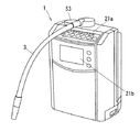
図4に示す電解水生成装置1の装置上面には使用者が、浄水、生成するアルカリイオン水、酸性イオン水の各モードの設定等の指令を入力及び表示をするための主表示操作部21aが形成されている。また、電解水生成装置1の上部から、生成されたアルカリ性イオン水が吐出される吐水パイプ3が引き出されて設けられている。さらに、電解水生成装置1上面には、電解質添加部50を開閉する添加筒キャップ53が露出して配設されている。
On the upper surface of the electrolyzed
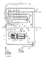
図1に電解水生成装置1の配管系統図を示す。
FIG. 1 shows a piping system diagram of the electrolyzed
まず、電解水生成装置1の構成について説明する。図1に示すように電解水生成装置1には、浄水カートリッジ4、流量センサ60、電解質添加部50及び電解槽62が内装されている。
First, the structure of the electrolyzed
浄水カートリッジ4は、導入された水を浄化するものであり、活性炭等の浄化剤6が充填された吸着浄化槽15と、吸着浄化槽15よりも下流側に配設され、中空糸膜等の濾過膜5が内装された濾過槽16とから構成されている。
The
浄水カートリッジ4の吸着浄化槽15の上流側端部(図中では下端部)には、浄水カートリッジ4に供給される水の流入口18が形成されており、濾過槽16の下流側端部(図中では上端部)には、浄水カートリッジ4から導出される流出口19が形成されている。
An
電解質添加部50は、円筒形状の外筒51の内部に、電解質を保持する内筒52が配設されており、この内筒52内には塩化カルシウム、乳酸カルシウム、グリセロリン酸カルシウム等のカルシウム塩や、塩化ナトリウム、塩化カリウム等の電解質が充填される。また、外筒51の上部開口には添加筒キャップ53が着脱自在に取付けられている。ここで、外筒51と添加筒キャップ53とは、Oリングを介して嵌合されて水密構造となっており、また、添加筒キャップ53の嵌合を離脱して内筒52を取り出し、電解質の補充ができるようになっている。
The
電解質添加部50の外筒51の下端部には、電解質添加部50に供給される水の流入口54が形成されている。また、電解質添加部50の外筒51の側面には、電解質添加部50から導出される水の流出口として上部流出口93と下部流出口92とが形成されている。ここで上部流出口93は外筒51の側面の上部に、下部流出口92は外筒51の側面の最下部にそれぞれ形成されており、上部流出口93の開口面積は、下部流出口92の開口面積よりも大きくなるように形成されている。この上部流出口93と下部流出口92の開口面積の比は適宜設定されるが、例えば下部流出口92の開口面積を上部流出口93の開口面積の0.1倍とするものである。
An
電解槽62の内部は、容器内部が電解隔膜63によって陽極室64と陰極室65に仕切られており、陽極室64には陽極66、陰極室65には陰極67が配設されている。ここで、図示の例では、陽極室64は容器内部奥に形成されると共に、陰極室65は陽極室64の周りを取り囲むように形成されており、陰極67は電解隔膜63を介して陽極66を取り囲むように円筒状に形成されている。従って、陰極室65は電解槽62の容器の外装と電解隔膜63とによって囲まれた空間で形成され、一方、陽極室64は電解隔膜63のみによって囲まれた空間にて形成されている。この陰極67及び陽極66は、この電極66,67間に電圧を印加するための電源(図示省略)に接続されている。
The inside of the
電解槽62の容器の外装には、水の排出口として排出口70が形成されており、排出口70は、容器の上端面に、電解隔膜63にて形成された通路23を介して陽極室64と連通するように形成されている。また、この容器の外装には、陰極室65から供給される水の流出口69が、容器の上端面に陰極室65と流路を介さず直接連通するように形成されており、この流出口69は空気取込口22を兼ねるものとして形成されている。
A discharge port 70 is formed as a water discharge port in the exterior of the container of the
さらにこの電解槽62の容器の外装には、電解槽62へ供給される水の流入口として、流入口68が形成されている。この流入口68は電解槽62の容器の側面下部に形成されており、陰極室65と陽極室64の双方に連通している。ここで、流入口68はこの開口の上方側において、電解隔膜63にて構成される連通路24を介して陽極室64と連通し、開口の下方側において陰極室65と流路を介さず直接連通している。
Furthermore, an
次に、電解水生成装置1に関する配管構成を説明する。
Next, the piping structure regarding the electrolyzed
水道の蛇口等の給水栓7と、電解水生成装置1の給水口2とは、給水ホース8によって接続されている。
A water supply tap 7 such as a water tap and the
電解水生成装置1内部においては、給水口2から導出された取水流路9は、浄水カートリッジ4の吸着浄化槽15の下部に流入口18にて接続されている。
Inside the electrolyzed
浄水カートリッジ4の濾過槽16の流出口19から導出された給水流路17の配管途中には、給水流路17における水の流量を測定する流量センサ60が配設されている。この流量センサ60は、例えばバネ力によって水流とは反対方向の回動力付勢された回動自在な羽体と、この羽体が給水流路17を流通する水の流圧によってバネ力に抗して回動された際の、その回動角度を測定する角度センサとによって構成されたものを用いることができる。給水流路17の下流側は、給水主流路14と排水流路10とに分岐されている。
A
排水流路10の下流側は電解質添加部50内に溜まった水を排水する排水弁30に接続されており、排水弁30の下流側には酸性水排出管72に接続されたバイパス流路120と排出管75に分岐されている。
The downstream side of the
また、給水主流路14の下流側は電解質添加部50の流入口54に接続されている。
Further, the downstream side of the water supply
電解質添加部50の上部流出口93からは、主供給路13が下方に向けて導出され、また、電解質添加部50の下部流出口92からは副供給路12が側方に向けて略水平に導出されている。主供給路13と副供給路12の流方向と直交する断面積の関係は、上部流出口93と下部流出口92との開口面積の関係と同様に、主供給路13の方が副供給路12よりも大きくなるように形成されている。この主供給路13と副供給路12は下流側において合流し、合流されて形成された添加水供給流路11の下流側は下方に導出されて、電解槽62の流入口68に接続されている。
The
電解槽62の上部流出口69からは吐水パイプ3が上方に向けて導出されており、この吐水パイプ3は装置外部に導出され、その下流側の先端は外部に向けて開口されている。また、電解槽62の排出口70からは酸性水排出管72が上方から側方、さらに下方に向けて導出されており、さらにこの酸性水排出管72は装置外部に導出され、その先端は外部に向けて開口されている。
The
次に、本発明の電解水生成装置1の表示操作部21の構成について説明する。表示操作部21は、図4に示すように、装置上面に配設された主表示操作部21aと、装置前面に配設された副表示操作部21bとで構成されている。
Next, the structure of the display operation part 21 of the electrolyzed
主表示操作部21aは図2に示すように、選択したモードを示すように、選択モードを表示する表示部40や各モードを選択するモード選択スイッチ41とで構成してある。
As shown in FIG. 2, the main
図2に示す主表示操作部21aでは、選択モードを表示する表示部40としては複数のモードに応じて複数個設けてあり、弱酸性イオン水生成モード用の表示部40a1、アルカリイオン水のレベル1生成モード用の表示部40a2、アルカリイオン水のレベル2生成モード用の表示部40a3、アルカリイオン水のレベル3生成モード用の表示部40a4、強アルカリイオン水生成モード用の表示部40a5、浄水モード用の表示部40a6がある。また、表示部40と一対のモード選択スイッチ41を設けてあり、弱酸性イオン水生成モード用のスイッチ41a1、アルカリイオン水のレベル1生成モード用のスイッチ41a2、アルカリイオン水のレベル2生成モード用のスイッチ41a3、アルカリイオン水のレベル3生成モード用のスイッチ41a4、強アルカリイオン水生成モード用のスイッチ41a5、浄水モード用のスイッチ41a6がある。これらの電解モードを表示する表示部40は、モード選択スイッチ41に隣接して形成されており、いずれかのスイッチを押すと、そのモードが選択されると共に、対応する表示部40が点灯するようになっている。
In the main
また、主表示操作部21aには、アルカリイオン水使用後に電極洗浄を実施しないように設定可能な連続モードを表示する表示部42aと連続モード選択スイッチ42bとが設けられている。
Further, the main
副表示操作部21bは、図3に示すように、浄水カートリッジ4の交換時期をレベルメーター的に表示する表示部47が設けられている。この表示部47としては、交換前の浄水カートリッジ4の使用中における、電解水生成装置1内を流通した水の流量の累積量を段階的に表示する複数の表示部47a1〜47a12と、この水の流量の累積量が所定値に達した場合に浄水カートリッジ4の交換が必要であることを表示する表示部47a13とが設けられている。また、この累積量をリセットするリセットスイッチ47bが隣接して設けられている。
As shown in FIG. 3, the sub
次に、本発明の電解水生成装置1の使用方法について説明する。
Next, the usage method of the electrolyzed
まず、電解モードとして、アルカリイオン水のレベル1生成モードにて電気分解を行う場合の動作を、図1の配管系統図、図5のブロック図、図6〜図8のフローチャートに基づいて説明する。なお、その他の電解モードで電気分解を行う場合も、アルカリイオン水のレベル1生成モードにて行う場合と同様に考えることができる。図1において水の流れを実線矢印で説明してある。
First, the operation in the case of performing electrolysis in the alkaline ionized
まず使用者は装置上面の主表示操作部21a上のアルカリイオン水のレベル1のスイッチ41a2を押してモードを選択する。このとき、表示部40a2は連動して点灯する。同様に他のスイッチ41を押して他のモードを選択した場合もそれぞれ連動した表示部40が点灯するようになっている。
First, the user selects a mode by pressing the
上記のように、スイッチ41を押してモード選択した状態で、給水栓7を開放して水道水等の原水を給水ホース8を通じて電解水生成装置1の給水口2へ供給する。
As described above, in the state where the
このとき、給水口2に送り込まれた原水は、取水流路9を通じて流入口18から浄水カートリッジ4へ送られ、吸着浄化槽15の浄化剤6にて、残留塩素、かび臭、トリハロメタン、農薬等が除去される。続いて濾過槽16の濾過膜5を通過することにより濾過されて微細な濁りや細菌等が除去される。このように、浄水カートリッジ4内に原水を通過させて濾過することにより、原水が浄水処理されて浄水が生成される。
At this time, the raw water sent to the
生成された浄水は、流出口19から給水流路17に流出するが、この給水流路17を流通する際に流量センサ60を通過する。
The generated purified water flows out from the
この流量センサ60から送られる信号に基づき、制御部49は、陽極67、陰極66間に電圧を印加し、電気分解を開始するかどうかの判断を行う(図5参照)。
Based on the signal sent from the
給水流路17を流通する浄水は、給水主流路14を通じて流入口54から電解質添加部50に供給される。
The purified water flowing through the
電解質添加部50に供給された浄水には、溶解した電解質が付与される。電解質を付与された水は、上部流出口93から主供給路13を介して、添加水供給流路11に流入し、流入口68から電解槽62の陰極室65及び陽極室64に供給される。このとき電解質添加部50内には、上部流出口93の形成位置まで水が供給された後にこの水が主として上部流出口93から流出されることとなり、電解質添加部50内にある程度滞留して電解質が充分に付与された水が電解質添加部50から流出される。
The purified water supplied to the
このとき、浄水カートリッジ4内を通過した浄水は電解質添加部50を通過してから電解槽62へ供給されることとなり、電解槽62に供給される水中の電解質濃度が充分に確保されることとなって、電解槽62における電気分解が効率よく行われることとなる。
At this time, the purified water that has passed through the
そして、電気分解によって、陰極室65でアルカリ性イオン水が生成されると共に、陽極室64で酸性イオン水が生成される。陰極室65で生成されたアルカリ性イオン水は、流出口69から吐水パイプ3に流入し、装置外部に導出される。一方、陽極室64で生成された酸性イオン水は、排出口70を通じて酸性水排出管72から装置外に排出されるものである。
Then, alkaline ionized water is generated in the
通水が検知された後、電気分解を開始する所定流量範囲で一定時間、すなわち一定総流量(これを第一の一定総流量と称する)が流れるまでは電解槽62内に水が充満されていないため、制御部49は、第一の一定総流量が流れるまで電気分解を行わない(図7(a)参照)。本実施例では、この第一の一定総流量の設定値を150cc(150cm3)としている。この間、「生成中」を表示する表示部46は、吐水パイプ3から水が吐出されておらず、電気分解も開始する前であるので、適した水ではないと判断され、制御部49により、消灯状態となる(図5参照)。
After the water flow is detected, the
この第一の一定総流量は、電解水生成装置1内(電解槽62や各流路を含む)に残存している水量に応じて補正されている(図9(a)参照)。従来では、残存水量が多くても少なくても関係なく一律にある一定量の水を通水した後に電気分解を行っていたが、本発明では、残存水量に応じて通水量(第一の一定総流量)を変化させることにより、必要充分な水を通水した後に電気分解を行うことができる。よって、上記の補正により、捨て水の量を大幅に減少させることができるものである。具体的には、止水から再通水までの時間が短い場合は、電解水生成装置1内の水があまり抜けていないため、第一の一定総流量の補正量(図9(a)の補正値に相当)を多く、止水から時間が経過し、電解水生成装置1内に残存している水量が減少していくにつれて第一の一定総流量の補正量(図9(a)の補正値に相当)を少なくなるよう、止水から再通水までの時間に応じて複数段に設定されている。
This first constant total flow rate is corrected according to the amount of water remaining in the electrolyzed water generating apparatus 1 (including the
このように制御部49は、給水栓7が開栓して再通水され、電解水生成装置1内に新たに流れ込んだ水の総流量と、止水時間に応じて電解水生成装置1内に残存している水量との合計量(図9(a)の初期値に相当)が一定量になるように、設定値を補正するのである。
As described above, the
本実施例では、図9のグラフに示すように、止水から再通水までの時間を、電解水生成装置1内に残存している水(浄水カートリッジ4以前を除く)がほぼ無くなった時間(50秒)を含め6段階に設定してある。
In the present embodiment, as shown in the graph of FIG. 9, the time from water stoppage to re-watering is the time when the water remaining in the electrolyzed water generating apparatus 1 (excluding the
また、他の実施例として、電解槽62内の水量を検出する水量センサ(図示省略)を電解水生成装置1に設け、この水量センサにより、実際の残存水量を検出してもよい。
As another example, a water amount sensor (not shown) for detecting the amount of water in the
第一の一定総流量が流れると、電解槽62内に水が充満し、電気分解が可能な状態となるが、電気分解をした水が所定のpHに到達するまでには時間差が生じるため、前記一定総流量以降に、さらに第二の一定総流量が流れるまでは適した水の状態とならない。いわばこの第二の一定総流量は、所望の電解水が得られるまでの過渡期の水量に相当する。よって、「生成中」を表示する表示部46は消灯を継続する。第二の一定総流量が流れ、適した水の状態となった場合に「生成中」を表示する表示部46は点灯になり(図9(b)、フローチャートは図7(a)参照)、使用者は容易に適した水ができたことが認識できるのである。本実施例では、この第二の一定総流量を150cc(150cm3)に設定してある。
When the first constant total flow rate flows, the
つまり、通水の検知から一定総流量に達したかどうかを流量センサ60による流量検出信号に基づいて制御部49が電気分解の要否と適した水か適していない水かを判断して「生成中」を表示する表示部46の表示を変更して告知するのである(図5参照)。本実施例では、最大300cc(300cm3)の一定総流量が流れた場合に「生成中」を表示する表示部が点灯するようになっている。
That is, whether or not the constant total flow rate has been reached from the detection of water flow is determined by the
なお、上記の動作において、電解槽62において印加される電圧の向きを逆向きにすると、陰極室65が陽極室としての機能を果たして酸性イオン水が生成されると共に、陽極室64が陰極室としての機能を果たしてアルカリイオン水が生成される。このときは酸性水が流出口69から吐水パイプ3に流入して電解水生成装置1外部に導出され、アルカリイオン水が排出口70を通じて酸性水排出管72から電解水生成装置1外に排出されるものである。
In the above operation, if the direction of the voltage applied in the
次に、電解水生成装置1内への水の供給を停止した場合の動作について説明する。
Next, the operation when the supply of water into the electrolyzed
使用者が給水栓7を閉止することにより電解水生成装置1への給水が停止されると、給水流路17における水の流通が停止されて、流量センサ60が止水状態になり、その信号が停止するため、制御部49は止水であることを判断する。止水後、吐水パイプ3中の水が抜けた後にこの吐水パイプ3の開口から空気が入り込む等して、この空気により、電解槽62中に残存する水が、酸性水排出管72や、バイパス流路120を経由して排出管75から徐々に抜け出て行く。本実施例では、止水後約50秒経過すると、電解水生成装置1内の水がほぼ無くなる(図9(a)参照)。このとき必要に応じて電極66,67間に逆方向の電圧が印加されて電極66,67の表面のスケールが除去された後、電解槽62における電極66,67間への電圧の印加が停止される。ちなみに、本実施例において、止水後に上記のように電極66,67の洗浄を行う場合には、止水後電解槽62から水が抜け切るまで約50秒間であるので(図9(a)参照)、この間に上記洗浄を行う必要がある。
When the water supply to the electrolyzed
逆電圧印加と同時に、表示部40は全て消灯し、電極洗浄中である旨を表示する電極洗浄中表示部45が点灯する(図5参照)。
Simultaneously with application of the reverse voltage, the
その後、装置内の浄水カートリッジ4から下流の流水路、電解質添加部50、電解槽62に滞留している滞留水の排水が排水弁30を開くことにより開始される。排水が完了した後、電極洗浄中表示部45が消灯し、表示部40(実施形態では表示部40a1)は点灯の状態となる。
Thereafter, drainage of the accumulated water remaining in the water flow path downstream from the
また、電極洗浄中及び電極洗浄終了後所定時間以内に再度、電解水生成装置1に水を流入した場合は、「生成中」を表示する表示部46は前記第一、第二とは別に、第三の一定総流量が流れるまでは、電極洗浄水が混入しているため、不適な水と判断して消灯状態を継続する。同時に、この状態の水は飲用すると体に害を及ぼす危険性があるので、警告音発生部48にて警告音を発生させて警告するようになっている。本実施例では、この第三の一定総流量を流量センサ60が通水を検知してから500cc(500cm3)に設定してある。また、他の実施例として、第一の一定総流量が流れてから、第三の一定総流量を設定してもよく(図9(b)、フローチャートは図7(a)参照)、この場合、第一の一定総流量は止水から再通水までの時間に応じて変化するため、不適な水と判断している期間を短縮することができる。
In addition, when water flows into the electrolyzed
また、上記のように止水の度に電極洗浄を実施すると、電極66,67の寿命は延命できるのであるが、使用者にとっては使用性は悪くなる。よって、止水した際に電極洗浄手段により電極66,67を洗浄する通常モードと、電極66,67を洗浄しない連続モードとを切り替えるスイッチとして連続モード選択スイッチ42bと、連続モードであることを表示する表示部42aとを主表示操作部21aに設け、できるだけ不適な水の排出を減らし、使用性を向上させるものである。なお、本実施例では、連続モードを採用しているが、この連続モードは止水時間が一定時間以上継続すると、自動的に解除するようにしてあり、連続モードは必要な場合のみ設定し、連続モードが不要な場合は、電極洗浄を実施して電極66,67の寿命を保つことができるのである。この連続モードにおいては、所定の電解モードで使用して止水した後に再通水する場合にも、止水前と同一の電解モードを継続させるようにしてある(フローチャートは、例えば、図6参照)。このことにより、従来では飲用に適さない強アルカリイオン水生成モードや酸性イオン水生成モードを使用した場合は、止水する度に飲用適なモードへと自動切替していたが、これらのモードも、通水・止水を繰り返して使用することができ、使用性を高めることができる。すなわち、飲用には不適であっても飲用とは別の用途で強アルカリイオン水や酸性イオン水を必要とする場合があるが、従来の電解水生成装置では、上記のイオン水を得るために選択していた電解モードは、誤飲防止のため止水後再通水する際に、飲用に適したイオン水を得るための電解モードに自動的に切り替えられ、強アルカリイオン水等を必要とする使用者にとっては使い勝手が悪いものであった。しかし、本発明に係る電解水生成装置1では、強アルカリイオン水等を得るために選択していた電解モードは、止水後再通水する際に切り替えられることなく、上記電解モードが再通水後も維持されるので、飲用とは別の用途で上記イオン水を使用する使用者にとっては使い勝手が良くなるものである。
Further, if the electrode cleaning is performed every time water is stopped as described above, the life of the
なお、連続モードの付加機能として、前記第二の一定総流量を通常モードより短く設定することもできる。これは、止水から再通水までの時間が短い場合は、電解水生成装置1内の水があまり抜けておらず、止水前の電解水が残留しているため、再通水した場合に所定のpHに到達する時間が短くなるためである。本実施例では、連続モード設定時には前記第二の一定総流量をゼロに設定してある。このことにより、さらに使用性を高めることができる。
As an additional function of the continuous mode, the second constant total flow rate can be set shorter than the normal mode. This is because when the time from stop water to re-watering is short, the water in the electrolyzed
また、他の実施例として、連続モードの代わりに、電解通水時間又は流量が一定量以上経過した後止水した場合のみ、電極洗浄を実施するようにしてもよく、この場合、止水と通水を繰り返す場合は複数回に1回電極洗浄を行うので、連続モードを設定しなくとも、止水後すぐに再通水しても、素早く適した水の生成が可能になるのである。 As another example, instead of the continuous mode, the electrode cleaning may be performed only when the water flow is stopped after a certain amount of time or the flow time of electrolysis has passed, and in this case, When the water flow is repeated, the electrode cleaning is performed once every plural times. Therefore, even if the continuous mode is not set, even if the water is passed again immediately after the water is stopped, it is possible to quickly generate suitable water.
さらに他の実施例として、前記連続モードが解除された後に、再通水した場合、電極66,67間に順電圧を印加して電気分解をする前の段階において、通水中に極性を反転させて電極を洗浄する通水洗浄モードを有してもよい(フローチャートは図7(b)参照)。また、前記連続モードが解除された後に再通水し、再び止水した場合、電極洗浄の印加電圧を通常より増大させる制御部49を有してもよい(フローチャートは図8(b)参照)。また、前記連続モードが解除された後に再通水し、再び止水した場合、電極洗浄の印加時間を通常より延長させる制御部49を有してもよい(フローチャートは図8(a)参照)。このことにより、連続モード時に省略された電極洗浄を補うことができ、電極66,67の寿命を延命することができるのである。
As another embodiment, when water is passed again after the continuous mode is released, the polarity is reversed during running in the stage before electrolysis is performed by applying a forward voltage between the
1 電解水生成装置
40 選択モードを表示する表示部
41 モード選択スイッチ
45 電極洗浄中表示部
46 生成中表示部
48 警告音発生部
49 制御部
60 流量センサ
62 電解槽
66 陽極
67 陰極
DESCRIPTION OF
Claims (5)
Priority Applications (1)
| Application Number | Priority Date | Filing Date | Title |
|---|---|---|---|
| JP2004024739A JP3991994B2 (en) | 2004-01-30 | 2004-01-30 | Electrolyzed water generator |
Applications Claiming Priority (1)
| Application Number | Priority Date | Filing Date | Title |
|---|---|---|---|
| JP2004024739A JP3991994B2 (en) | 2004-01-30 | 2004-01-30 | Electrolyzed water generator |
Publications (2)
| Publication Number | Publication Date |
|---|---|
| JP2005211853A JP2005211853A (en) | 2005-08-11 |
| JP3991994B2 true JP3991994B2 (en) | 2007-10-17 |
Family
ID=34907333
Family Applications (1)
| Application Number | Title | Priority Date | Filing Date |
|---|---|---|---|
| JP2004024739A Expired - Fee Related JP3991994B2 (en) | 2004-01-30 | 2004-01-30 | Electrolyzed water generator |
Country Status (1)
| Country | Link |
|---|---|
| JP (1) | JP3991994B2 (en) |
Families Citing this family (2)
| Publication number | Priority date | Publication date | Assignee | Title |
|---|---|---|---|---|
| JP4572901B2 (en) * | 2007-01-12 | 2010-11-04 | パナソニック電工株式会社 | Electrolyzed water generator |
| JP4678051B2 (en) * | 2008-12-05 | 2011-04-27 | パナソニック電工株式会社 | Electrolyzed water generator |
-
2004
- 2004-01-30 JP JP2004024739A patent/JP3991994B2/en not_active Expired - Fee Related
Also Published As
| Publication number | Publication date |
|---|---|
| JP2005211853A (en) | 2005-08-11 |
Similar Documents
| Publication | Publication Date | Title |
|---|---|---|
| WO2012063582A1 (en) | Electrolyzed water producing device | |
| JP2010156117A (en) | Hand finger washing device | |
| WO2018168109A1 (en) | Apparatus for generating electrolyzed hydrogen water | |
| KR20140087296A (en) | Water purifier and cleanning method for the same | |
| JP4697293B2 (en) | Water treatment equipment | |
| JP3991995B2 (en) | Electrolyzed water generator | |
| JP2005211853A (en) | Electrolytic water generator | |
| JP3882509B2 (en) | Electrolyzed water generator | |
| JP4463928B2 (en) | Water treatment equipment | |
| KR20130077383A (en) | Water purifier | |
| JP2006305568A (en) | Electrolytic cell, ionic water purifier adopting the same and method for cleaning the same | |
| JP2001170635A (en) | Water reformer | |
| JP3835173B2 (en) | Electrolyzed water generator | |
| JP4481047B2 (en) | Ionized water generator | |
| JP5155251B2 (en) | Water conditioner | |
| JP3319841B2 (en) | Electrolyzed water generator | |
| JP3835283B2 (en) | Electrolyzed water generator | |
| JPH08173964A (en) | Electrolyzed water generator | |
| JP3835177B2 (en) | Electrolyzed water generator | |
| JP4617165B2 (en) | Ion water conditioner | |
| JP3835176B2 (en) | Electrolyzed water generator | |
| JP3840699B2 (en) | Alkaline ion water conditioner | |
| JP4481056B2 (en) | Ionized water generator | |
| JP3752941B2 (en) | Electrolyzed water generator | |
| JP3392130B2 (en) | Electrolyzed water generator |
Legal Events
| Date | Code | Title | Description |
|---|---|---|---|
| A621 | Written request for application examination |
Free format text: JAPANESE INTERMEDIATE CODE: A621 Effective date: 20051216 |
|
| A977 | Report on retrieval |
Free format text: JAPANESE INTERMEDIATE CODE: A971007 Effective date: 20070629 |
|
| TRDD | Decision of grant or rejection written | ||
| A01 | Written decision to grant a patent or to grant a registration (utility model) |
Free format text: JAPANESE INTERMEDIATE CODE: A01 Effective date: 20070703 |
|
| A61 | First payment of annual fees (during grant procedure) |
Free format text: JAPANESE INTERMEDIATE CODE: A61 Effective date: 20070716 |
|
| FPAY | Renewal fee payment (event date is renewal date of database) |
Free format text: PAYMENT UNTIL: 20100803 Year of fee payment: 3 |
|
| S533 | Written request for registration of change of name |
Free format text: JAPANESE INTERMEDIATE CODE: R313533 |
|
| FPAY | Renewal fee payment (event date is renewal date of database) |
Free format text: PAYMENT UNTIL: 20100803 Year of fee payment: 3 |
|
| R350 | Written notification of registration of transfer |
Free format text: JAPANESE INTERMEDIATE CODE: R350 |
|
| FPAY | Renewal fee payment (event date is renewal date of database) |
Free format text: PAYMENT UNTIL: 20110803 Year of fee payment: 4 |
|
| FPAY | Renewal fee payment (event date is renewal date of database) |
Free format text: PAYMENT UNTIL: 20120803 Year of fee payment: 5 |
|
| FPAY | Renewal fee payment (event date is renewal date of database) |
Free format text: PAYMENT UNTIL: 20130803 Year of fee payment: 6 |
|
| LAPS | Cancellation because of no payment of annual fees |