JP4057724B2 - Support structure of bridge girder in extrusion method - Google Patents
Support structure of bridge girder in extrusion method Download PDFInfo
- Publication number
- JP4057724B2 JP4057724B2 JP32188198A JP32188198A JP4057724B2 JP 4057724 B2 JP4057724 B2 JP 4057724B2 JP 32188198 A JP32188198 A JP 32188198A JP 32188198 A JP32188198 A JP 32188198A JP 4057724 B2 JP4057724 B2 JP 4057724B2
- Authority
- JP
- Japan
- Prior art keywords
- bridge girder
- tensile force
- saddle
- support structure
- temporary
- Prior art date
- Legal status (The legal status is an assumption and is not a legal conclusion. Google has not performed a legal analysis and makes no representation as to the accuracy of the status listed.)
- Expired - Fee Related
Links
Images
Landscapes
- Bridges Or Land Bridges (AREA)
Description
【0001】
【発明の属する技術分野】
本発明は、プレストレストコンクリート橋の架設工法の一つとして一般に知られている押出し工法において、押出し架設時に橋桁に生ずる曲げ応力に抵抗する目的で用いられる橋桁の支持構造に関する。
【0002】
【従来の技術】
従来のこの種の橋桁の支持構造としては、例えば、押出し架設されるべき橋桁の支間の中央部に立設される支柱と、一方の端部を支柱の頂部に定着し、他方の端部を橋桁の支間方向の前部に定着して張架してなる前部斜材、及び一方の端部を支柱の頂部に定着し、他方の端部を橋桁の支間方向の後部に定着して張架してなる後部斜材からなる仮設斜材と、支柱の頂部を上下に移動して仮設斜材の引張力を調整するジャッキとを含むものが知られている。
【0003】
かかる橋桁の支持構造によれば、ジャッキを用いて支柱の頂部を上下に移動させて仮設斜材にあらかじめ設定された値の引張力を導入することにより、橋桁の片持ち張り出し部に上昇力を与えることが可能となることから、隣接する製作ヤードで製作した橋桁を押出し装置を用いて片側から順次押出して大スパンの架設を行うことができる。
【0004】
ところで、仮設斜材に導入された引張力は、押出し架設に伴う、橋桁の片持ち張り出し部の長さ寸法の変化、橋脚による橋桁の支持位置の変化、仮設斜材から本設斜材への引張力負担の一部盛り替えなどにより複雑に順次変動する。このため、従来における押出し架設では、仮設斜材の引張力の変動をリアルタイムで測定し管理しながら、支柱の頂部の上下移動を行い、これによって仮設斜材の引張力を調整することとしていた。
【0005】
【発明が解決しようとする課題】
しかしながら、従来の橋桁の支持構造では、押出し架設時に仮設斜材の引張力が複雑に順次変動する結果、前後で異なる値となりアンバランスになっても、当該引張力の調整が支柱の上下移動のみによってしか行えず、前後で別個に行えないため、かかるアンバランスの解消が実際上かなり困難であり、片持ち張り出し部が上又は下へと撓んでしまう等、ひびわれの発生ひいては落橋の虞が生じてしまう。
【0006】
一方、従来の橋桁の支持構造において、前後に二列に配置したジャッキを用いてかかるアンバランスを解消しようとすると、上記複雑に順次変動する引張力を瞬時に的確に調整することは事実上不可能であり、かかるアンバランスが解消されるまでに相当の時間が経過してしまうことから、ひびわれの発生ひいては落橋の虞を除去できない。
【0007】
そこで、本発明の目的は、押出し架設時に斜材の引張力が複雑に順次変動しても、前後でアンバランスにならず、ひびわれの発生ひいては落橋の虞の生じない、押出し工法における橋桁の支持構造を提供することにある。
【0008】
【課題を解決するための手段】
上記目的を達成するために、本発明に係る押出し工法における橋桁の支持構造は、押出されるべき橋桁の支間の中央部に立設される支柱と、この支柱の頂部に設けられるサドルと、両端部の夫々を前記橋桁の支間方向の前後に対して定着し、中央部を前記サドルに対して滑動自在に張架してなる斜材と、前記サドルを上下に移動させて前記斜材の引張力を調整する前後で一対に配置された引張力調整手段と、を含み、前記サドルが、前記一対の引張力調整手段により前後で吊下支持されていることを特徴としている。
【0009】
即ち、本発明は、中央部を支柱頂部のサドルに対して滑動自在に張架した斜材によって橋桁の前後を吊下支持し、サドルの上下移動による斜材の引張力の意識的調整及びサドル上での斜材の滑動による斜材の引張力の無意識的調整を重畳的に行いながら橋桁の押出し架設をすることにより、斜材の引張力が複雑に順次変動しても、前後でアンバランスにならず、ひびわれの発生ひいては落橋の虞の生じない、押出し工法における橋桁の支持構造の実現をするものである。
【0010】
【発明の実施の形態】
以下、添付図面に示す実施の形態に基づいてこの発明を詳細に説明する。
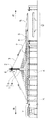
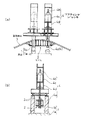
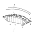
図1は、本発明の一実施の形態に係る押出し工法における橋桁の支持構造の全体概略を示す側面図、図2は、当該押出し工法における橋桁の支持構造の支柱近傍の部分詳細を示す正面図(図2a)及び側面図(図2b)、図3は、当該押出し工法における橋桁の支持構造のサドルの詳細を示す斜視図、である。
【0011】
図1及び図2において、符号Hは、押出されるべきプレストレストコンクリート製の橋桁、符号Kは、当該橋桁H及び将来構築する橋桁を連続的に支持する橋脚、符号Yは、鉄筋の組立、コンクリートの打設等を行って橋桁Hの分割製作をする製作ヤード、符号Dは、現に供用されている既設道路、を示している。
【0012】
また、符号1は、この橋桁Hの支間の中央部に立設される支柱、を示している。これは、本設である主塔1aと、この主塔1aの頂部に一体に立設される仮設であるピロン柱1bとから構成されている。尚、本実施の形態に係る橋桁Hは、供用開始後は既設道路D上を高架する高速道路の架道橋として利用されるものである。
【0013】
更に、符号2は、このピロン柱1bの頂部に設けられるサドル、符号3は、両端部の夫々を前記橋桁Hの支間方向の前後に対して定着し、中央部を前記サドル2に対して滑動自在に張架してなる仮設斜材、を示している。
【0014】
更にまた、符号4は、前記サドル2を上下に移動させて前記仮設斜材3の引張力を調整する引張力調整手段たるリフティングジャッキ、を示している。これは、定着具4aを用いてサドル2を一体に吊下支持する鉛直鋼材4bと、この鉛直鋼材4bを介してサドル2を上下に移動させるジャッキ本体4cと、ピロン柱1bの頂部において当該ジャッキ本体4cを受けて支持するジャッキ受桁4dとから構成されている。
【0015】
また、符号5は、橋桁Hの片持ち張り出し部の実質長さを短くし、押出し架設時に生ずる曲げ応力を低減する手延べ桁、符号6は、手延べ桁5に上昇力を与え、押出し架設時に生ずる曲げ応力を低減する仮設水平材、符号7は、橋桁Hの押出し架設の過程において順次張架される本設斜材、を示している。
【0016】
本実施の形態において、サドル2は、図3に示すように、前後で放射状に列状配置され、上端部でもって仮想の曲面を形成している板状部材11と、これらの板状部材11と一体になって強靱な構造の実現をする構造部材12と、リフティングジャッキ4の構成要素たる鉛直鋼材4bが挿通され、前後で一対となっている鋼管13と、上記仮想の曲面に沿う曲率を有していると共に仮設斜材3が滑動自在に張架され、左右で一対となっている半割ベント管14とから構成されている。
【0017】
次に、本実施の形態に係る押出し工法における橋の支持構造の作用について図1〜図3を用いて説明する。
【0018】
まず、準備作業として、製作ヤードYにおいてコンクリートを打ち継ぎながら製作された橋桁Hの支間の中央部において主塔1a及び頂部にサドル2を有するピロン柱1bを立設する。そして、仮設斜材3の両端部の夫々を前記橋桁Hの前後に対して定着し、中央部をサドル2に対して滑動自在に張架し、更に橋桁H及び手延べ桁5の間において仮設水平材6を張架する。
【0019】
続いて、一方では、仮設斜材3に対してあらかじめ設定された値の引張力が導入されると、橋桁Hの片持ち張り出し部に上昇力が与えられ、他方では、仮設水平材6に対してあらかじめ設定された値の引張力が導入されると、手延べ桁5に上昇力が与えられる。これにより、橋桁H及び手延べ桁5は本実施の形態に係る押出し工法における橋桁Hの支持構造によって安定的に支持された状態におかれる。
【0020】
このような状態において橋桁Hの押出し架設が行われる。即ち、仮設斜材3の引張力の変動をリアルタイムで測定し管理しながら押出し装置(図示外)を用いて橋桁Hを片側から順次押出してゆき、仮設斜材3から本設斜材7への引張力負担の一部盛り替え、手延べ桁5架設後における本設水平材の引張力の解放等のプロセスを経た後に、最終的には既設道路D上への橋桁Hの架設が完結するのである。
【0021】
このとき、押出し架設に伴う、橋桁Hの片持ち張り出し部の長さ寸法の変化、橋脚Kによる橋桁Hの支持位置の変化、及び仮設斜材3から本設斜材7への引張力負担の一部盛り替えなどにより、仮設斜材3に導入された引張力が複雑に順次変動する結果、当該引張力が前後で異なる値となりアンバランスが生じようとする。
【0022】
しかし、本実施の形態では、サドル2の上下移動により仮設斜材3の引張力が意識的に調整されるというだけでなく、サドル2の上下移動の有無に関係なく、仮設斜材3がサドル2上において自己修正的に滑動し、当該引張力が無意識的に瞬時にバランス調整されるから、当該引張力は前後で異なる値となってアンバランスが生ずる事態は未然に回避されることになる。
【0023】
従って、本実施の形態によれば、中央部を支柱1頂部のサドル2に対して滑動自在に張架している仮設斜材3によって橋桁Hの前後を吊下支持し、仮設斜材3の引張力の意識的調整及び無意識的調整を重畳的に行いながら橋桁Hの押出し架設を行うことができるので、仮設斜材3の引張力が複雑に順次変動することとなっても、前後でアンバランスになることはなく、橋桁Hの片持ち張り出し部が上又は下へと撓んでしまうことにはならない。よって、ひびわれの発生の虞がないし、落橋の虞も勿論生じない。
【0024】
【発明の効果】
本発明によれば、以上のように構成したため、押出し架設時に斜材の引張力が複雑に順次変動しても、前後でアンバランスにならず、ひびわれの発生ひいては落橋の虞の生じない、押出し工法における橋桁の支持構造の実現が可能になる。
【図面の簡単な説明】
【図1】本発明の一実施の形態に係る押出し工法における橋桁の支持構造の全体概略を示す側面図である。
【図2】本発明の一実施の形態に係る押出し工法における橋桁の支持構造の支柱近傍の部分詳細を示す正面図及び側面図である。
【図3】本発明の一実施の形態に係る押出し工法における橋桁の支持構造のサドルの詳細を示す斜視図である。
【符号の説明】
1…支柱
1a…主塔
1b…ピロン柱
2…サドル
3…仮設斜材
4…リフティングジャッキ
4a…定着具
4b…鉛直鋼材
4c…ジャッキ本体
4d…ジャッキ受桁
5…手延べ桁
6…仮設水平材
7…本設斜材
11…板状部材
12…構造部材
13…鋼管
14…半割ベント管
H…橋桁
K…橋脚
Y…製作ヤード
D…既設道路[0001]
BACKGROUND OF THE INVENTION
The present invention relates to a support structure for a bridge girder used for the purpose of resisting bending stress generated in a bridge girder in an extrusion method generally known as one of construction methods for a prestressed concrete bridge.
[0002]
[Prior art]
As a conventional support structure for this type of bridge girder, for example, a support column standing at the center of a span of a bridge girder to be extruded and one end fixed to the top of the support column, and the other end is fixed. A front diagonal member fixed and stretched at the front part of the bridge girder, and one end fixed to the top of the column, and the other end fixed to the rear part of the bridge girder. There are known ones including a temporary diagonal member made up of a rear diagonal member and a jack that moves the top of the column up and down to adjust the tensile force of the temporary diagonal member.
[0003]
According to such a support structure of the bridge girder, the top of the column is moved up and down using a jack, and a tensile force having a preset value is introduced into the temporary diagonal member, so that a rising force is applied to the cantilever projecting part of the bridge girder. Therefore, it is possible to construct a large span by sequentially extruding bridge girders produced at adjacent production yards from one side using an extrusion device.
[0004]
By the way, the tensile force introduced into the temporary diagonal is changed in the length dimension of the cantilever overhang of the bridge girder, the change in the support position of the bridge girder by the bridge pier, from the temporary diagonal to the main diagonal. Fluctuates sequentially in a complicated manner due to partial replacement of the tensile load. For this reason, in the conventional extrusion construction, the top of the column is moved up and down while measuring and managing the fluctuation of the tensile force of the temporary diagonal member in real time, thereby adjusting the tensile force of the temporary diagonal member.
[0005]
[Problems to be solved by the invention]
However, in the conventional bridge girder support structure, the tensile force of the temporary slanting material fluctuates in a complicated and sequential manner during extrusion construction, and even if it becomes different values before and after and becomes unbalanced, the adjustment of the tensile force only moves up and down the column. This can only be done by the front and rear, so it is practically difficult to eliminate this imbalance, and the cantilever overhangs upward or downward, causing cracks and possibly falling bridges. End up.
[0006]
On the other hand, in the conventional bridge girder support structure, if it is attempted to eliminate such imbalance by using jacks arranged in two rows on the front and rear sides, it is practically impossible to adjust the above-mentioned complicated and sequentially changing tensile force instantaneously and accurately. It is possible, and since a considerable amount of time elapses before such unbalance is eliminated, the possibility of cracking and the failure of a fallen bridge cannot be eliminated.
[0007]
Therefore, the object of the present invention is to support the bridge girder in the extrusion method, in which even if the tensile force of the diagonal member fluctuates in a complicated manner at the time of extrusion construction, it does not become unbalanced before and after, and cracks will not occur and there is no risk of falling bridges. To provide a structure.
[0008]
[Means for Solving the Problems]
In order to achieve the above object, the support structure of the bridge girder in the extrusion method according to the present invention includes a column that is erected at the center of the span of the bridge girder to be extruded, a saddle that is provided at the top of the column, and both ends. Each of the portions is fixed to the front and rear in the span direction of the bridge girder, and a diagonal member in which a central portion is slidably stretched with respect to the saddle, and the saddle is moved up and down to pull the diagonal member. seen including a tension adjusting means disposed in a pair before and after adjusting the force, the said saddle is characterized in that it is the lower support suspended before and after by the pair of tension adjusting means.
[0009]
That is, the present invention suspends and supports the front and rear of a bridge girder by a diagonal member slidably stretched with respect to the saddle at the top of the column, and consciously adjusts the tensile force of the diagonal member by the vertical movement of the saddle and the saddle. Even if the tensile force of the diagonal member fluctuates in a complicated manner, the balance is unbalanced by pushing the bridge girder while unconsciously adjusting the tensile force of the diagonal member due to the sliding of the diagonal member. Therefore, the support structure of the bridge girder in the extrusion method is realized without cracking and the possibility of falling bridges.
[0010]
DETAILED DESCRIPTION OF THE INVENTION
Hereinafter, the present invention will be described in detail based on embodiments shown in the accompanying drawings.
FIG. 1 is a side view showing an overall outline of a support structure of a bridge girder in an extrusion method according to an embodiment of the present invention, and FIG. 2 is a front view showing a partial detail in the vicinity of a column of the support structure of the bridge girder in the extrusion method. (FIG. 2a), a side view (FIG. 2b), and FIG. 3 are perspective views showing details of a saddle of a support structure for a bridge girder in the extrusion method.
[0011]
1 and 2, symbol H is a prestressed concrete bridge girder to be extruded, symbol K is a bridge pier that continuously supports the bridge girder H and a bridge girder to be constructed in the future, symbol Y is rebar assembly, concrete A production yard in which the bridge girder H is divided and manufactured by performing the placement of the above, reference numeral D indicates an existing road that is actually in use.
[0012]
[0013]
Further,
[0014]
Further,
[0015]
Reference numeral 5 is a hand girder that shortens the substantial length of the cantilever overhanging portion of the bridge girder H and reduces bending stress generated during the extrusion erection, and
[0016]
In the present embodiment, as shown in FIG. 3, the
[0017]
Next, the effect | action of the support structure of the bridge in the extrusion method concerning this Embodiment is demonstrated using FIGS. 1-3.
[0018]
First, as a preparatory work, a
[0019]
Subsequently, on the one hand, when a tensile force having a preset value is introduced to the temporary
[0020]
In such a state, the bridge girder H is pushed out. That is, while the fluctuation of the tensile force of the temporary diagonal 3 is measured and managed in real time, the bridge girder H is sequentially pushed out from one side using an extrusion device (not shown), and the temporary diagonal 3 is transferred to the permanent diagonal 7. After the replacement of part of the tensile force burden and the process of releasing the tensile force of the main horizontal member after the construction of the hand girders 5 and so on, the construction of the bridge girder H on the existing road D is finally completed. is there.
[0021]
At this time, a change in the length of the cantilever projecting portion of the bridge girder H due to the extrusion construction, a change in the support position of the bridge girder H by the bridge pier K, and a load of tensile force from the temporary diagonal 3 to the main diagonal 7 As a result of partial replacement, etc., the tensile force introduced into the temporary
[0022]
However, in the present embodiment, not only the tensile force of the temporary
[0023]
Accordingly, according to the present embodiment, the front and rear of the bridge girder H are suspended and supported by the temporary
[0024]
【The invention's effect】
According to the present invention, since it is configured as described above, even when the tensile force of the diagonal member fluctuates in a complicated manner at the time of extrusion erection, it does not become unbalanced before and after the crack, and the occurrence of cracks and the possibility of falling bridges do not occur. The support structure of the bridge girder in the construction method can be realized.
[Brief description of the drawings]
FIG. 1 is a side view showing an overall outline of a support structure for a bridge girder in an extrusion method according to an embodiment of the present invention.
FIGS. 2A and 2B are a front view and a side view showing details of a portion in the vicinity of a column of a support structure for a bridge girder in an extrusion method according to an embodiment of the present invention. FIGS.
FIG. 3 is a perspective view showing details of a saddle of a support structure for a bridge girder in an extrusion method according to an embodiment of the present invention.
[Explanation of symbols]
DESCRIPTION OF
Claims (1)
両端部の夫々を前記橋桁の支間方向の前後に対して定着し、中央部を前記サドルに対して滑動自在に張架してなる斜材と、
前記サドルを上下に移動させて前記斜材の引張力を調整する前後で一対に配置された引張力調整手段と、を含み、
前記サドルが、前記一対の引張力調整手段により前後で吊下支持されていることを特徴とする、押出し工法における橋桁の支持構造。A column erected at the center of the span of the bridge girder to be extruded, a saddle provided at the top of the column,
An oblique member in which both ends are fixed with respect to the front and rear in the span direction of the bridge girder, and a central portion is slidably stretched with respect to the saddle,
See containing and a tensile force adjusting means disposed in a pair before and after adjusting the tensile force of the diagonal members by moving the saddle in the vertical,
A support structure for a bridge girder in an extrusion method , wherein the saddle is suspended and supported by the pair of tensile force adjusting means in the front-rear direction .
Priority Applications (1)
| Application Number | Priority Date | Filing Date | Title |
|---|---|---|---|
| JP32188198A JP4057724B2 (en) | 1998-11-12 | 1998-11-12 | Support structure of bridge girder in extrusion method |
Applications Claiming Priority (1)
| Application Number | Priority Date | Filing Date | Title |
|---|---|---|---|
| JP32188198A JP4057724B2 (en) | 1998-11-12 | 1998-11-12 | Support structure of bridge girder in extrusion method |
Publications (2)
| Publication Number | Publication Date |
|---|---|
| JP2000144637A JP2000144637A (en) | 2000-05-26 |
| JP4057724B2 true JP4057724B2 (en) | 2008-03-05 |
Family
ID=18137456
Family Applications (1)
| Application Number | Title | Priority Date | Filing Date |
|---|---|---|---|
| JP32188198A Expired - Fee Related JP4057724B2 (en) | 1998-11-12 | 1998-11-12 | Support structure of bridge girder in extrusion method |
Country Status (1)
| Country | Link |
|---|---|
| JP (1) | JP4057724B2 (en) |
Cited By (1)
| Publication number | Priority date | Publication date | Assignee | Title |
|---|---|---|---|---|
| CN111206505A (en) * | 2019-12-18 | 2020-05-29 | 中铁四局集团有限公司 | Suspension rod installation and tensioning construction scheme of highway and railway dual-purpose bridge |
Families Citing this family (9)
| Publication number | Priority date | Publication date | Assignee | Title |
|---|---|---|---|---|
| JP4558609B2 (en) * | 2005-08-30 | 2010-10-06 | オリエンタル白石株式会社 | Extrusion construction method of bridge |
| JP4889774B2 (en) * | 2009-09-28 | 2012-03-07 | 日本車輌製造株式会社 | Bridge girder delivery method and bridge girder horizontal method |
| KR101313886B1 (en) * | 2011-12-19 | 2013-11-15 | 코비코리아 주식회사 | Apparatus for constructing V-shaped tower to reduce cross-section of top of bridge using jack-up and method thereof |
| CN102899990B (en) * | 2012-08-31 | 2014-12-03 | 湖南路桥建设集团有限责任公司 | Hook-shaped lifting saddle and supporting structure of rail rope |
| CN112709137B (en) * | 2020-12-15 | 2022-09-09 | 中国水利水电第八工程局有限公司 | Hoisting construction method for stiffening beam of suspension bridge |
| CN113005910B (en) * | 2021-03-02 | 2022-05-27 | 浙江交工集团股份有限公司 | Construction method of adjustable cable saddle integral high-precision positioning structure |
| CN113512940B (en) * | 2021-03-18 | 2022-07-08 | 中铁十一局集团第一工程有限公司 | Low tower cable-stayed bridge cable beam anchoring block construction process based on adjustable brackets |
| CN114808697A (en) * | 2022-05-31 | 2022-07-29 | 中铁大桥勘测设计院集团有限公司 | Construction structure system and construction method of large-pre-deviation main cable saddle |
| CN117569196B (en) * | 2023-11-07 | 2026-03-31 | 中铁大桥勘测设计院集团有限公司 | A saddle suitable for distributed main cables |
-
1998
- 1998-11-12 JP JP32188198A patent/JP4057724B2/en not_active Expired - Fee Related
Cited By (1)
| Publication number | Priority date | Publication date | Assignee | Title |
|---|---|---|---|---|
| CN111206505A (en) * | 2019-12-18 | 2020-05-29 | 中铁四局集团有限公司 | Suspension rod installation and tensioning construction scheme of highway and railway dual-purpose bridge |
Also Published As
| Publication number | Publication date |
|---|---|
| JP2000144637A (en) | 2000-05-26 |
Similar Documents
| Publication | Publication Date | Title |
|---|---|---|
| EP0080321B1 (en) | Composite, pre-stressed, structural member and method of making same | |
| JP3940211B2 (en) | Construction method of horizontal beams for concrete main tower. | |
| JP4569878B2 (en) | Bridge girder construction method | |
| JP5045214B2 (en) | Column head construction method | |
| JP4057724B2 (en) | Support structure of bridge girder in extrusion method | |
| JP4777922B2 (en) | Mobile suspension support | |
| CN115305817B (en) | A construction method for cast-in-place steel truss support for high-altitude large-span upper crossbeam of cable tower | |
| CN108708265A (en) | A kind of steel camber arch bridge construction method | |
| JP2006077521A (en) | Bridge construction device | |
| JPH05106210A (en) | How to construct a concrete cable-stayed bridge | |
| CN111851317B (en) | Method for installing arch ring of arch bridge | |
| CN110295548A (en) | The makeshift device of mechanical balance is maintained under the bridge construction technique of fitting the arch first then fitting the girder | |
| CN106894345A (en) | Continuous beam end bay closing device and method | |
| JPH10183999A (en) | Method of building movable form for arched concrete body | |
| JP6509096B2 (en) | Extension method | |
| CN119266118A (en) | A jacking support structure and construction method for a high-speed large-span steel box girder | |
| CN117051699B (en) | Integrated Structure and Construction Method of Variable Width Cast-in-Place Box Girder Formwork and Wing Plate Support | |
| CN118704367A (en) | Asynchronous construction control method for continuous beams combining hanging basket preloading with external support | |
| CN111877126B (en) | Method for installing arch ring of arch bridge | |
| JP2020186516A (en) | Method of constructing bridge railing | |
| JP3790229B2 (en) | Bridge construction method and bridge construction apparatus | |
| CN116463956A (en) | A non-destructive support formwork system and construction method for hollow columns with low piers and curved surfaces of continuous girder bridges | |
| CN210507162U (en) | Temporary device for maintaining mechanical balance under bridge construction process of arch-first and beam-second | |
| CN114892523A (en) | A kind of construction method of bridge side span closing | |
| JP3827111B2 (en) | Construction method of concrete bridge girder |
Legal Events
| Date | Code | Title | Description |
|---|---|---|---|
| A621 | Written request for application examination |
Free format text: JAPANESE INTERMEDIATE CODE: A621 Effective date: 20050805 |
|
| A977 | Report on retrieval |
Free format text: JAPANESE INTERMEDIATE CODE: A971007 Effective date: 20070801 |
|
| A131 | Notification of reasons for refusal |
Free format text: JAPANESE INTERMEDIATE CODE: A131 Effective date: 20070815 |
|
| A521 | Written amendment |
Free format text: JAPANESE INTERMEDIATE CODE: A523 Effective date: 20071002 |
|
| TRDD | Decision of grant or rejection written | ||
| A01 | Written decision to grant a patent or to grant a registration (utility model) |
Free format text: JAPANESE INTERMEDIATE CODE: A01 Effective date: 20071205 |
|
| A61 | First payment of annual fees (during grant procedure) |
Free format text: JAPANESE INTERMEDIATE CODE: A61 Effective date: 20071214 |
|
| R150 | Certificate of patent or registration of utility model |
Free format text: JAPANESE INTERMEDIATE CODE: R150 |
|
| FPAY | Renewal fee payment (event date is renewal date of database) |
Free format text: PAYMENT UNTIL: 20101221 Year of fee payment: 3 |
|
| FPAY | Renewal fee payment (event date is renewal date of database) |
Free format text: PAYMENT UNTIL: 20111221 Year of fee payment: 4 |
|
| FPAY | Renewal fee payment (event date is renewal date of database) |
Free format text: PAYMENT UNTIL: 20111221 Year of fee payment: 4 |
|
| FPAY | Renewal fee payment (event date is renewal date of database) |
Free format text: PAYMENT UNTIL: 20121221 Year of fee payment: 5 |
|
| FPAY | Renewal fee payment (event date is renewal date of database) |
Free format text: PAYMENT UNTIL: 20121221 Year of fee payment: 5 |
|
| FPAY | Renewal fee payment (event date is renewal date of database) |
Free format text: PAYMENT UNTIL: 20131221 Year of fee payment: 6 |
|
| LAPS | Cancellation because of no payment of annual fees |