JP4072012B2 - Flat cable connecting part, manufacturing method and manufacturing apparatus - Google Patents
Flat cable connecting part, manufacturing method and manufacturing apparatus Download PDFInfo
- Publication number
- JP4072012B2 JP4072012B2 JP2002204387A JP2002204387A JP4072012B2 JP 4072012 B2 JP4072012 B2 JP 4072012B2 JP 2002204387 A JP2002204387 A JP 2002204387A JP 2002204387 A JP2002204387 A JP 2002204387A JP 4072012 B2 JP4072012 B2 JP 4072012B2
- Authority
- JP
- Japan
- Prior art keywords
- flat
- conductive sheets
- connector
- flat cable
- conductor
- Prior art date
- Legal status (The legal status is an assumption and is not a legal conclusion. Google has not performed a legal analysis and makes no representation as to the accuracy of the status listed.)
- Expired - Fee Related
Links
Images


Landscapes
- Processing Of Terminals (AREA)
- Multi-Conductor Connections (AREA)
- Coupling Device And Connection With Printed Circuit (AREA)
- Insulated Conductors (AREA)
Description
【0001】
【発明の属する技術分野】
本発明は、電気機器や自動車等の電気配線で用いられるフラットケーブルの接続部、その製造方法及びその製造装置に関するものである。
【0002】
【従来の技術】
電気機器や自動車等の電気配線に、図30に示すように幅Wcの銅やアルミニュウム等の金属よりなるフラット導体1を、ポリエチレンテレフタレートの如きプラスチックよりなるフラット絶縁被覆2で覆ったフラットケーブル3が用いられるようになってきている。このフラットケーブル3の接続方法として、接続子4´としてフラット導体1の幅Wcより狭い幅Wの端子板5の幅方向の両側にクリンプ片6を立設し、端子板5の端部に雌形の接続継ぎ手7を一体に形成した構造のものを用いて、図31に示すようにこの接続子4´のクリンプ片6をフラット導体1に対応する箇所でフラットケーブル3に突き刺して該クリンプ片6をフラット導体1に導通させ、フラットケーブル3を突き抜けた各クリンプ片6の先端部を円弧状に曲成して加締めてフラットケーブル接続部8´を形成することが開発されている。
【0003】
この場合、フラットケーブル3は、フラット導体1として、従来の丸電線の断面積 0.3sqmmや 0.5sqmmに相当する導体厚さが0.15mmで、導体幅Wcが 1.5mm〜 2.0mmのものが、2.3 mmの配列ピッチでフラット絶縁被覆2内に配列された構造のものが用いられている。
【0004】
一方、接続子4´の端子板5としては厚さが0.25mmで、幅Wが 1.2mmのものが用いられている。各クリンプ片6は、端子板5の幅方向の両側に該端子板5の幅方向に突出するように打ち抜いたものを立ち上げて形成されている。
【0005】
【発明が解決しようとする課題】
しかしながら、近年、このようなフラットケーブル接続部8´を形成するフラットケーブル3がさらに高密度化され、従来の丸電線の断面積 0.3sqmmより小さく、導体幅がさらに狭くなったフラット導体1を、従来より狭いピッチで配置したファインピッチのフラットケーブル3の使用が要求されるようになってきている。
【0006】
このファインピッチのフラットケーブル3は、具体的にはフラット導体1が厚さ0.035 mmで、幅Wc 1.2mmや 1.0mmのものが、2.0 mmや1.8 mmの配列ピッチでフラット絶縁被覆2内に配列された構造のものである。この場合、フラット導体1の配列ピッチは、耐電圧の関係から 0.8mm以上必要である。
【0007】
このようにフラット導体1の幅が従来より狭くなり、その厚さも薄くなることで、従来のように接続子4´のクリンプ片6をフラット導体1に対応する箇所でフラットケーブル3に突き刺し、フラットケーブル3を突き抜けた各クリンプ片6の先端部を曲成して加締めてフラットケーブル接続部8´を形成する方法では、接続子4´の端子板5の幅をさらに狭くしなければならず、フラットケーブル3を突き抜けた各クリンプ片6の先端部を円弧状に曲成することが寸法的にできなくなり、またフラット導体1の厚さがより薄くなることで、クリンプ片6をフラット導体1に突き刺しす際にフラット導体1が押し曲がりながら突き刺されるため、クリンプ片6とフラット導体1との電気的接触状態が安定せず、フラットケーブル接続部8´の信頼性が低下する問題点がある。
【0008】
本発明の目的は、高密度化されたフラットケーブルでも接続部の信頼性が優れたフラットケーブル接続部及びその製造方法を提供することにある。
【0009】
本発明の他の目的は、高密度化されたフラットケーブルでも接続部の信頼性をより向上できるフラットケーブル接続部及びその製造方法を提供することにある。
【0010】
本発明の他の目的は、段違い部分をつぶれ難くすることができるフラットケーブル接続部及びその製造方法を提供することにある。
【0011】
本発明の他の目的は、段違い部分がつぶれるのを防止できるフラットケーブル接続部を提供することにある。
【0012】
本発明の他の目的は、段違い部分の表面の絶縁を維持できるフラットケーブル接続部を提供することにある。
【0013】
本発明の他の目的は、フラットケーブルと導電シートとが重なり合った重ね合せ部に、フラットケーブルのフラット導体の箇所で切れ目を入れ、この切れ目に直交する両側の部分を重ね合せ部の積層方向に段違いにする作業を一挙に行えるフラットケーブル接続部の製造方法及び製造装置を提供することにある。
【0014】
本発明の他の目的は、フラット導体と導電シートとの電気的・機械的な接続を安定させることができるフラットケーブル接続部の製造方法及び製造装置を提供することにある。
【0015】
【課題を解決するための手段】
本発明に係るフラットケーブル接続部の一態様においては、重ね合された2枚の導電シートを備えて該2枚の導電シートの基端部が電気的及び機械的に接続された構造を有する接続子が設けられる。またフラット導体をフラット絶縁被覆で被覆してなるフラットケーブルが前記接続子の2枚の導電シートの間に挟まれて2枚の導電シートとフラットケーブルとが重ね合された重ね合せ部が形成される。そして、接続子の2枚の導電シートと、フラットケーブルの2枚の導電シートの間に挟まれている部分のフラット絶縁被覆及びフラット導体とを貫通した1条の切れ目が重ね合せ部に入れられて、その切れ目に直交する両側の部分が相対的に重ね合せ部の積層方向に段違いにされ、切れ目に沿った部分の両端の部分にフラット導体と導電シートが接触した接触部がそれぞれ形成される。
【0016】
このような構造のフラットケーブル接続部によれば、高密度化されて、幅が狭く、厚みの薄いフラット導体を用いたフラットケーブルでも、その重ね合せ部にフラット導体の箇所で1条の切れ目を入れ、その切れ目に直交する両側の部分を相対的に重ね合せ部の積層方向に段違いにするだけで容易に形成することができる。また、このフラットケーブル接続部では、クリンプ片を有する接続子を用いないので、幅が狭く、厚みの薄いフラット導体が用いられていても、接続の信頼性の低下を招くことなく容易に形成することができる。
【0017】
また、本発明に係るフラットケーブル接続部の他の態様においては、重ね合された2枚の導電シートを備えて該2枚の導電シートの基端部が電気的及び機械的に接続された構造を有する接続子が設けられ、フラット導体をフラット絶縁被覆で被覆してなるフラットケーブルが接続子の2枚の導電シートの間に挟まれて2枚の導電シートとフラットケーブルとが重ね合された重ね合せ部が形成される。そして、接続子の2枚の導電シートと、フラットケーブルの2枚の導電シートの間に挟まれている部分のフラット絶縁被覆及びフラット導体とを貫通した2条の切れ目が重ね合せ部にほぼ平行に入れられて、2条の切れ目の間の部分がその幅方向の両側の部分に対して重ね合せ部の積層方向に段違いにされ、各切れ目に沿った部分の両端の部分にフラット導体と導電シートが接触した接触部がそれぞれ形成される。
【0018】
このような構造のフラットケーブル接続部によれば、高密度化されて、幅が狭く、厚みの薄いフラット導体を用いたフラットケーブルでも、その重ね合せ部にフラット導体の箇所で2条の切れ目を入れ、この2条の切れ目の間の部分をその幅方向の両側の部分に対して重ね合せ部の積層方向に段違いにするだけで容易に形成することができる。また、このフラットケーブル接続部では、クリンプ片を有する接続子を用いないので、幅が狭く、厚みの薄いフラット導体が用いられていても、接続の信頼性の低下を招くことなく容易に形成することができる。
【0019】
また、本発明に係るフラットケーブル接続部の更に他の態様では、重ね合された2枚の導電シートを備えて該2枚の導電シートの基端部が電気的及び機械的に接続された構造を有する接続子が設けられ、フラット導体をフラット絶縁被覆で被覆してなるフラットケーブルが2枚の導電シートの間に挟まれて2枚の導電シートとフラットケーブルとが重ね合された重ね合せ部が形成される。そして、接続子の2枚の導電シートと、フラットケーブルの2枚の導電シートの間に挟まれている部分のフラット絶縁被覆及びフラット導体とを貫通した3条の切れ目が重ね合せ部にほぼ平行に入れられて、3条の切れ目の間の2つの部分が隣接相互間で突出方向を逆にしてこれら2つの部分の幅方向の両側の部分に対して前記重ね合せ部の積層方向に段違いにされ、各切れ目に沿った部分の両端の部分にフラット導体と導電シートが接触した接触部がそれぞれ形成される。
【0020】
フラットケーブル接続部を上記のように構成すると、高密度化されて、幅が狭く、厚みの薄いフラット導体を用いたフラットケーブルでも、その重ね合せ部にフラット導体の箇所で3条の切れ目を入れ、この3条の切れ目の間の2つの部分を隣接相互間で突出方向を逆にしてこれら2つの部分の幅方向の両側の部分に対して重ね合せ部の積層方向に段違いにするだけで容易に形成することができる。特に、このフラットケーブル接続部では、3条の切れ目を入れているので、接触部の数が増え、十分に導通をとることができる。また、このフラットケーブル接続部では、クリンプ片を有する接続子を用いないので、幅が狭く、厚みの薄いフラット導体が用いられていても、接続の信頼性の低下を招くことなく容易に形成することができる。
【0021】
また、上記の如き本発明に係るフラットケーブル接続部では、切れ目に沿って重ね合せ部の積層方向に段違いにされている部分は、切れ目に沿った部分が重ね合せ部の積層方向の一方側に凸で、次に中立位置に戻り、次に前記重ね合せ部の積層方向の他方側に凸となる形状となっていることが好ましい。
【0022】
このような構成になっていると、凸部にこれを押圧する力が作用した場合、隣り合う反対方向に突出する凸部の存在により、押圧された凸部がつぶれるのを防止することができる。
【0023】
また、本発明に係るフラットケーブル接続部の他の態様では、重ね合された2枚の導電シートを備えて該2枚の導電シートの基端部が電気的及び機械的に接続された構造を有する接続子が設けられて、フラット導体をフラット絶縁被覆で被覆してなるフラットケーブルが2枚の導電シートの間に挟まれて2枚の導電シートとフラットケーブルとが重ね合された重ね合せ部が形成され、接続子の2枚の導電シートと、フラットケーブルの2枚の導電シートの間に挟まれている部分のフラット絶縁被覆及びフラット導体とを貫通したコ字状またはV字状の切れ目が重ね合せ部に入れられて舌片が形成される。また、この舌片とこれに隣接する重ね合せ部の部分が前記重ね合せ部の積層方向に段違いにされ、舌片の基端の部分の両側にフラット導体と前記導電シートとが接触した接触部がそれぞれ形成される。
【0024】
フラットケーブル接続部を上記のように構成すると、高密度化されて、幅が狭く、厚みの薄いフラット導体を用いたフラットケーブルでも、その重ね合せ部にフラット導体の箇所でコ字状またはV字状の切れ目を入れて舌片を形成し、この舌片とこれに隣接する重ね合せ部の部分を重ね合せ部の積層方向に段違いにするだけで容易に形成することができる。また、このフラットケーブル接続部では、クリンプ片を有する接続子を用いないので、幅が狭く、厚みの薄いフラット導体が用いられていても、接続の信頼性の低下を招くことなく容易に形成することができる。
【0025】
また、本発明に係るフラットケーブル接続部では、切れ目を入れる部分を避けて、2枚の導電シートの一方に沿って延びる補強片が接続子に設けられていることが好ましい。
【0026】
このような構造のフラットケーブル接続部では、補強片によりこのフラットケーブル接続部の部分が曲がり難くなり、接続部の信頼性を向上させることができる。
【0027】
また、本発明に係るフラットケーブル接続部の他の態様では、重ね合された2枚の導電シートを備えて該2枚の導電シートの基端部が電気的及び機械的に接続された構造を有する接続子が設けられ、フラット導体をフラット絶縁被覆で被覆した構造を有する2条のフ ラットケーブルが交差した状態で重ね合されて、2条のフラットケーブルの交差して重ね合された部分が接続子を構成する2枚の導電シートの間に挟まれる。これにより、2枚の導電シートと2条のフラットケーブルの交差した部分との重ね合せ部が形成される。また接続子の2枚の導電シートと、該2枚の導電シートの間に挟まれている2条のフラットケーブルの交差した部分のフラット絶縁被覆及びフラット導体とを貫通した1条の切れ目が重ね合せ部に入れられて、その切れ目に直交する両側の部分が相対的に重ね合せ部の積層方向に段違いにされ、切れ目に沿った部分の両端の部分にフラット導体と導電シートが接触した接触部が形成される。
【0028】
フラットケーブル接続部を上記のように構成すると、高密度化されて、幅が狭く、厚みの薄いフラット導体を用いたフラットケーブルでも、その重ね合せ部にフラット導体の箇所で1条の切れ目を入れ、その切れ目に直交する両側の部分を相対的に重ね合せ部の積層方向に段違いにするだけで容易に形成することができる。また、このフラットケーブル接続部では、クリンプ片を有する接続子を用いないので、幅が狭く、厚みの薄いフラット導体が用いられていても、接続の信頼性の低下を招くことなく容易に形成することができる。
【0029】
また、上記の如き本発明に係るフラットケーブル接続部では、切れ目に沿って重ね合せ部の積層方向に段違いにされている部分は、切れ目に沿った部分が重ね合せ部の積層方向の一方側に凸で、次に中立位置に戻り、次に前記重ね合せ部の積層方向の他方側に凸となる形状となっていることが好ましい。
【0030】
このような構成になっていると、凸部にこれを押圧する力が作用した場合、隣り合う反対方向に突出する凸部の存在により、押圧された凸部がつぶれるのを防止することができる。
【0031】
また、本発明に係るフラットケーブル接続部の更に他の態様では、重ね合された2枚の導電シートを備えて該2枚の導電シートの基端部が電気的及び機械的に接続された構造を有する接続子が設けられ、フラット導体をフラット絶縁被覆で被覆した構造を有する2条のフラットケーブルが交差した状態で重ね合されて、2条のフラットケーブルの交差して重ね合された部分が、接続子を構成する2枚の導電シートの間に挟まれる。これにより、2枚の導電シートと2条のフラットケーブルの交差した部分との重ね合せ部が形成される。また接続子の2枚の導電シートと、該2枚の導電シートの間に挟まれている2条のフラットケーブルの交差した部分のフラット絶縁被覆及びフラット導体とを貫通したコ字状またはV字状の切れ目が重ね合せ部に入れられて舌片が形成され、この舌片とこれに隣接する重ね合せ部の部分が重ね合せ部の積層方向に段違いにされて、舌片の基端の部分の両側にフラット導体と導電シートとが接触した接触部がそれぞれ形成される。
【0032】
フラットケーブル接続部を上記のように構成すると、高密度化されて、幅が狭く、厚みの薄いフラット導体を用いたフラットケーブルでも、その重ね合せ部にフラット導体の箇所でコ字状またはV字状の切れ目を入れて舌片を形成し、この舌片とこれに隣接する重ね合せ部の部分を重ね合せ部の積層方向に段違いにするだけで容易に形成することができる。また、このフラットケーブル接続部では、クリンプ片を有する接続子を用いないので、幅が狭く、厚みの薄いフラット導体が用いられていても、接続の信頼性の低下を招くことなく容易に形成することができる。
【0033】
また、本発明に係るフラットケーブル接続部の更の他の態様では、重ね合された2枚の導電シートを備えて該2枚の導電シートの基端部が電気的及び機械的に接続された構造を有する接続子が設けられ、フラット導体をフラット絶縁被覆で被覆してなる2条のフラットケーブルが、それぞれの端部を向かい合わせにして配置される。この場合、2条のフラ ットケーブルの向かい合わせにされた端部が接続子の2枚の導電シートの間に挟まれて、2枚の導電シートと2条のフラットケーブルの向かい合わせにされた端部との重ね合せ部が形成される。また接続子の2枚の導電シートと、各フラットケーブルの2枚の導電シートの間に挟まれている部分のフラット絶縁被覆及びフラット導体とを貫通した1条の切れ目が、2条のフラットケーブルのそれぞれの側に設けられて、各切れ目に直交する両側の部分が相対的に重ね合せ部の積層方向に段違いにされ、各切れ目に沿った部分の両端の部分にフラット導体と導電シートが接触した接触部が形成される。
【0034】
フラットケーブル接続部を上記のように構成すると、高密度化されて、幅が狭く、厚みの薄いフラット導体を用いたフラットケーブルでも、その重ね合せ部にフラット導体の箇所で1条の切れ目を入れ、その切れ目に直交する両側の部分を相対的に重ね合せ部の積層方向に段違いにするだけで容易に形成することができる。また、このフラットケーブル接続部では、クリンプ片を有する接続子を用いないので、幅が狭く、厚みの薄いフラット導体が用いられていても、接続の信頼性の低下を招くことなく容易に形成することができる。
【0035】
また、本発明に係るフラットケーブル接続部の他の態様では、重ね合された2枚の導電シートを備えて該2枚の導電シートの基端部が電気的及び機械的に接続された構造を有する接続子が設けられ、フラット導体をフラット絶縁被覆で被覆してなる2条のフラットケーブルが、それぞれの端部を向かい合わせにして配置される。また2条のフラットケーブルの向かい合わせにされた端部が接続子の2枚の導電シートの間に挟まれて、2枚の導電シートと2条のフラットケーブルの向かい合わせにされた端部との重ね合せ部が形成され、接続子の2枚の導電シートと、各フラットケーブルの該2枚の導電シートの間に挟まれている部分のフラット絶縁被覆及びフラット導体とを貫通した互いに平行な2条の切れ目が、2条のフラットケーブルのそれぞれの側に設けられる。そして、各2条の切れ目の間の部分がその幅方向の両側の部分に対して重ね合せ部の積層方向に段違いにされ、各切れ目に沿った部分の両端の部分にフラット導体と導電シートが接触した接触部がそれぞれ形成される。
【0036】
フラットケーブル接続部を上記のように構成すると、高密度化されて、幅が狭く、厚みの薄いフラット導体を用いたフラットケーブルでも、その重ね合せ部にフラット導体の箇所で2条の切れ目を入れ、この2条の切れ目の間の部分をその幅方向の両側の部分に対して重ね合せ部の積層方向に段違いにするだけで容易に形成することができる。また、このフラットケーブル接続部では、クリンプ片を有する接続子を用いないので、幅が狭く、厚みの薄いフラット導体が用いられていても、接続の信頼性の低下を招くことなく容易に形成することができる。
【0037】
また、本発明に係るフラットケーブル接続部の他の態様では、重ね合された2枚の導電シートを備えて該2枚の導電シートの基端部が電気的及び機械的に接続された構造を有する接続子が設けられるとともに、フラット導体をフラット絶縁被覆で被覆してなる2条のフラットケーブルが、それぞれの端部を向かい合わせにして配置され、2条のフラットケーブルの向かい合わせにされた端部が接続子の2枚の導電シートの間に挟まれて、2枚の導電シートと2条のフラットケーブルの向かい合わせにされた端部との重ね合せ部が形成される。また接続子の2枚の導電シートと各フラットケーブルの2枚の導電シートの間に挟まれている部分のフラット絶縁被覆及びフラット導体とを貫通した互いに平行な3条の切れ目が、2条のフラットケーブルのそれぞれの側に設けられて、3条の切れ目の間の2つの部分が隣接相互間で突出方向を逆にしてこれら2つの部分の幅方向の両側の部分に対して前記重ね合せ部の積層方向に段違いにされ、各切れ目に沿った部分の両端の部分にフラット導体と導電シートとが接触した接触部がそれぞれ形成される。
【0038】
このようにフラットケーブル接続部を構成すると、高密度化されて、幅が狭く、厚みの薄いフラット導体を用いたフラットケーブルでも、その重ね合せ部にフラット導体の箇所で3条の切れ目を入れ、この3条の切れ目の間の2つの部分を隣接相互間で突出方向を逆にしてこれら2つの部分の幅方向の両側の部分に対して重ね合せ部の積層方向に段違いにするだけで容易に形成することができる。特に、このフラットケーブル接続部では、3条の切れ目を入れているので、接触部の数が増え、十分に導通をとることができる。また、このフラットケーブル接続部では、クリンプ片を有する接続子を用いないので、幅が狭く、厚みの薄いフラット導体が用いられていても、接続の信頼性の低下を招くことなく容易に形成することができる。
【0039】
また、上記の如き本発明に係るフラットケーブル接続部では、切れ目に沿って重ね合せ部の積層方向に段違いにされている部分は、切れ目に沿った部分が重ね合せ部の積層方向の一方側に凸で、次に中立位置に戻り、次に前記重ね合せ部の積層方向の他方側に凸となる形状となっていることが好ましい。
【0040】
このような構成になっていると、凸部にこれを押圧する力が作用した場合、隣り合う反対方向に突出する凸部の存在により、押圧された凸部がつぶれるのを防止することができる。
【0041】
また、本発明に係るフラットケーブル接続部の他の態様では、重ね合された2枚の導電シートを備えて該2枚の導電シートの基端部が電気的及び機械的に接続された構造を有する接続子が設けられるとともに、フラット導体をフラット絶縁被覆で被覆してなる2条のフラットケーブルが、それぞれの端部を向かい合わせにして配置され、2条のフラットケーブルの向かい合わせにされた端部が接続子の2枚の導電シートの間に挟まれて、2枚の導電シートと2条のフラットケーブルの向かい合わせにされた端部との重ね合せ部が形成される。また接続子の2枚の導電シートと、各フラットケーブルの前記2枚の導電シートの間に挟まれている部分のフラット絶縁被覆及びフラット導体とを貫通したコ字状またはV字状の切れ目が前記2条のフラットケーブルのそれぞれの側に入れられて舌片が形成されて、舌片とこれに隣接する前記重ね合せ部の部分が前記重ね合せ部の積層方向に段違いにされ、舌片の基端の部分の両側にフラット導体と導電シートが接触した接触部がそれぞれ形成される。
【0042】
上記のようにフラットケーブル接続部が構成されていると、高密度化されて、幅が狭く、厚みの薄いフラット導体を用いたフラットケーブルでも、その重ね合せ部にフラット導体の箇所でコ字状またはV字状の切れ目を入れて舌片を形成し、この舌片とこれに隣接する重ね合せ部の部分を重ね合せ部の積層方向に段違いにするだけで容易に形成することができる。また、このフラットケーブル接続部では、クリンプ片を有する接続子を用いないので、幅が狭く、厚みの薄いフラット導体が用いられていても、接続の信頼性の低下を招くことなく容易に形成することができる。
【0043】
また、本発明に係るフラットケーブル接続部では、上記の如きフラットケーブル接続部で、重ね合せ部の段違い部分の凹部内に、その段違い形状を維持させる形状維持手段が設けられていることが好ましい。
【0044】
このように重ね合せ部の段違い部分の凹部内に、その段違い形状を維持させる形状維持手段を設けると、段違い部分に加圧力が加わっても段違い形状がつぶれるのを防止でき、接続部の信頼性を向上させることができる。
【0045】
また、本発明に係るフラットケーブル接続部では、重ね合せ部の段違い部分を覆って絶縁被覆が被せられていることが好ましい。
【0046】
このように重ね合せ部の段違い部分を覆って絶縁被覆を被せると、段違い部分の絶縁を維持させることができる。
【0047】
次に、本発明に係るフラットケーブル接続部の製造方法では、重ね合された2枚の導電シートを備えて該2枚の導電シートの基端部が電気的及び機械的に接続された構造を有する接続子を用意し、フラット導体をフラット絶縁被覆で被覆してなるフラットケーブルを2枚の導電シートの間に挟んで2枚の導電シートとフラットケーブルとが重ね合された重ね合せ部を形成する。そして、接続子の2枚の導電シートと、フラットケーブルの2枚の導電シートの間に挟まれている部分のフラット絶縁被覆とフラット導体とを貫通した1条の切れ目を重ね合せ部に入れ、切れ目に直交する両側の部分を相対的に前記重ね合せ部の積層方向に段違いにして、切れ目に沿った部分の両端の部分にフラット導体と導電シートが接触した接触部を形成する。
【0048】
このようなフラットケーブル接続部の製造方法によれば、高密度化されて、幅が狭く、厚みの薄いフラット導体を用いたフラットケーブルでも、その重ね合せ部にフラット導体の箇所で1条の切れ目を入れ、その切れ目に直交する両側の部分を相対的に重ね合せ部の積層方向に段違いにするだけで容易に形成することができる。また、このフラットケーブル接続部の製造方法では、クリンプ片を有する接続子を用いないので、幅が狭く、厚みの薄いフラット導体が用いられていても、接続の信頼性の低下を招くことなく容易に形成することができる。
【0049】
また、本発明に係るフラットケーブル接続部の製造方法の他の態様においては、重ね合された2枚の導電シートを備えて該2枚の導電シートの基端部が電気的及び機械的に接続された構造を有する接続子を用意し、フラット導体をフラット絶縁被覆で被覆してなるフラットケーブルを2枚の導電シートの間に挟んで2枚の導電シートとフラットケーブルとが重ね合された重ね合せ部を形成する。そして、接続子の2枚の導電シートと、フラットケーブルの2枚の導電シートの間に挟まれている部分のフラット絶縁被覆及びフラット導体とを貫通した互いに平行な2条の切れ目を重ね合せ部に入れ、2条の切れ目の間の部分をその幅方向の両側の部分に対して重ね合せ部の積層方向に段違いにして、各切れ目に沿った部分の両端の部分にフラット導体と導電シートが接触した接触部をそれぞれ形成する。
【0050】
このようなフラットケーブル接続部の製造方法によれば、高密度化されて、幅が狭く、厚みの薄いフラット導体を用いたフラットケーブルでも、その重ね合せ部にフラット導体の箇所で2条の切れ目を入れ、この2条の切れ目の間の部分をその幅方向の両側の部分に対して重ね合せ部の積層方向に段違いにするだけで容易に形成することができる。また、このフラットケーブル接続部の製造方法では、クリンプ片を有する接続子を用いないので、幅が狭く、厚みの薄いフラット導体が用いられていても、接続の信頼性の低下を招くことなく容易に形成することができる。
【0051】
また、本発明に係るフラットケーブル接続部の製造方法の他の態様では、重ね合された2枚の導電シートを備えて該2枚の導電シートの基端部が電気的及び機械的に接続された構造を有する接続子を用意し、フラット導体をフラット絶縁被覆で被覆してなるフラットケーブルを接続子の2枚の導電シートの間に挟んで2枚の導電シートとフラットケーブルとが重ね合された重ね合せ部を形成する。そして、接続子の2枚の導電シートとフラットケーブルの2枚の導電シートの間に挟まれている部分のフラット絶縁被覆及びフラット導体とを貫通した互いに平行な3条の切れ目を重ね合せ部に入れて、3条の切れ目の間の2つの部分を隣接相互間で突出方向を逆にしてこれら2つの部分の幅方向の両側の部分に対して前記重ね合せ部の積層方向に段違いにし、各切れ目に沿った部分の両端の部分にフラット導体と導電シートが接触した接触部をそれぞれ形成する。
【0052】
このようなフラットケーブル接続部の製造方法によれば、高密度化されて、幅が狭く、厚みの薄いフラット導体を用いたフラットケーブルでも、その重ね合せ部にフラット導体の箇所で3条の切れ目を入れ、この3条の切れ目の間の2つの部分を隣接相互間で突出方向を逆にしてこれら2つの部分の幅方向の両側の部分に対して重ね合せ部の積層方向に段違いにするだけで容易に形成することができる。特に、このフラットケーブル接続部の製造方法では、3条の切れ目を入れているので、接触部の数が増え、十分に導通をとることができる。また、このフラットケーブル接続部の製造方法では、クリンプ片を有する接続子を用いないので、幅が狭く、厚みの薄いフラット導体が用いられていても、接続の信頼性の低下を招くことなく容易に形成することができる。
【0053】
また、上記の如き本発明に係るフラットケーブル接続部の製造方法では、切れ目に沿って重ね合せ部の積層方向に段違いにする部分は、切れ目に沿った部分が重ね合せ部の積層方向の一方側に凸で、次に中立位置に戻り、次に前記重ね合せ部の積層方向の他方側に凸となる形状とすることが好ましい。
【0054】
このような構成にすると、凸部にこれを押圧する力が作用した場合、隣り合う反対方向に突出する凸部の存在により、押圧された凸部がつぶれるのを防止することができる。
【0055】
また、本発明に係るフラットケーブル接続部の製造方法の他の態様では、重ね合された2枚の導電シートを備えて該2枚の導電シートの基端部が電気的及び機械的に接続された構造を有する接続子を用意し、フラット導体をフラット絶縁被覆で被覆してなるフラットケーブルを2枚の導電シートの間に挟んで2枚の導電シートとフラットケーブルとが重ね合された重ね合せ部を形成する。また接続子の2枚の導電シートと、フラットケーブルの2枚の導電シートの間に挟まれている部分のフラット絶縁被覆及びフラット導体とを貫通したコ字状またはV字状の切れ目を重ね合せ部に入れて舌片を形成し、舌片とこれに隣接する重ね合せ部の部分を重ね合せ部の積層方向に段違いにして、舌片の基端の部分の両側にフラット導体と導電シートとが接触した接触部をそれぞれ形成する。
【0056】
このようなフラットケーブル接続部の製造方法によれば、高密度化されて、幅が狭く、厚みの薄いフラット導体を用いたフラットケーブルでも、その重ね合せ部にフラット導体の箇所でコ字状またはV字状の切れ目を入れて舌片を形成し、この舌片とこれに隣接する重ね合せ部の部分を重ね合せ部の積層方向に段違いにするだけで容易に形成することができる。また、このフラットケーブル接続部の製造方法では、クリンプ片を有する接続子を用いないので、幅が狭く、厚みの薄いフラット導体が用いられていても、接続の信頼性の低下を招くことなく容易に形成することができる。
【0057】
また、本発明に係るフラットケーブル接続部の製造方法の更に他の態様においては、重ね合された2枚の導電シートを備えて該2枚の導電シートの基端部が電気的及び機械的に接続された構造を有する接続子を用意し、フラット導体をフラット絶縁被覆で被覆した構造を有する2条のフラットケーブルを交差した状態で重ね合せる。また2条のフラットケーブルの交差して重ね合された部分を接続子の2枚の導電シートの間に挟んで、2枚の導電シートと2条のフラットケーブルの交差した部分との重ね合せ部を形成し、接続子の2枚の導電シートと、該2枚の導電シートの間に挟まれている2条のフラットケーブルの交差した部分のフラット絶縁被覆及びフラット導体とを貫通した1条の切れ目を前記重ね合せ部に入れて、その切れ目に直交する両側の部分を相対的に前記重ね合せ部の積層方向に段違いにし、切れ目に沿った部分の両端の部分にフラット導体と導電シートが接触した接触部を形成する。
【0058】
このようなフラットケーブル接続部の製造方法によれば、高密度化されて、幅が狭く、厚みの薄いフラット導体を用いたフラットケーブルでも、その重ね合せ部にフラット導体の箇所で1条の切れ目を入れ、この切れ目に直交する両側の部分を相対的に重ね合せ部の積層方向に段違いにするだけで容易に形成することができる。また、このフラットケーブル接続部の製造方法では、クリンプ片を有する接続子を用いないので、幅が狭く、厚みの薄いフラット導体が用いられていても、接続の信頼性の低下を招くことなく容易に形成することができる。
【0059】
また本発明に係るフラットケーブル接続部の製造方法の他の態様では、重ね合された2枚の導電シートを備えて該2枚の導電シートの基端部が電気的及び機械的に接続された構造を有する接続子を用意し、フラット導体をフラット絶縁被覆で被覆した構造をそれぞれが有する2条のフラットケーブルを交差させた状態で重ね合せる。また2条のフラットケーブルの交差して重ね合された部分を接続子の2枚の導電シートの間に挟んで、2枚の導電シートと2条のフラットケーブルの交差した部分との重ね合せ部を形成し、接続子の2枚の導電シートと、2枚の導電シートの間に挟まれている2条のフラットケーブルの交差した部分のフラット絶縁被覆及びフラット導体とを貫通したほぼ平行な2条の切れ目を前記重ね合せ部に入れて、2条の切れ目の間の部分をその幅方向の両側の部分に対して前記重ね合せ部の積層方向に段違いにし、各切れ目に沿った部分の両端の部分にフラット導体と前記導電シートが接触した接触部をそれぞれ形成する。
【0060】
また本発明に係るフラットケーブル接続部の製造方法の他の態様では、重ね合された2枚の導電シートを備えて該2枚の導電シートの基端部が電気的及び機械的に接続された構造を有する接続子を用意し、フラット導体をフラット絶縁被覆で被覆した構造を有する2条のフラットケーブルを交差させた状態で重ね合せる。また2条のフラットケーブルの交差して重ね合された部分を接続子の2枚の導電シートの間に挟んで、2枚の導電シートと2条のフラットケーブルの交差した部分との重ね合せ部を形成し、接続子の2枚の導電シートと該2枚の導電シートの間に挟まれている2条のフラットケーブルの交差した部分のフラット絶縁被覆及びフラット導体とを貫通したほぼ平行な3条の切れ目を前記重ね合せ部にほぼ平行に入れる。そして、3条の切れ目の間の2つの部分を隣接相互間で突出方向を逆にしてこれら2つの部分の幅方向の両側の部分に対して重ね合せ部の積層方向に段違いにし、各切れ目に沿った部分の両端の部分にフラット導体と導電シートが接触した接触部をそれぞれ形成する。
【0061】
このようなフラットケーブル接続部の製造方法によれば、高密度化されて、幅が狭く、厚みの薄いフラット導体を用いたフラットケーブルでも、その重ね合せ部にフラット導体の箇所で3条の切れ目を入れ、この3条の切れ目の間の2つの部分を隣接相互間で突出方向を逆にしてこれら2つの部分の幅方向の両側の部分に対して重ね合せ部の積層方向に段違いにするだけで容易に形成することができる。特に、このフラットケーブル接続部の製造方法では、3条の切れ目を入れているので、接触部の数が増え、十分に導通をとることができる。また、このフラットケーブル接続部の製造方法では、クリンプ片を有する接続子を用いないので、幅が狭く、厚みの薄いフラット導体が用いられていても、接続の信頼性の低下を招くことなく容易に形成することができる。
【0062】
また、本発明に係るフラットケーブル接続部の製造方法においては、重ね合された2枚の導電シートを備えて該2枚の導電シートの基端部が電気的及び機械的に接続された構造を有する接続子を用意し、フラット導体をフラット絶縁被覆で被覆した構造をそれぞれが有する2条のフラットケーブルを交差させた状態で重ね合せる。また2条のフラットケーブルの交差して重ね合された部分を接続子の2枚の導電シートの間に挟んで、2枚の導電シートと2条のフラットケーブルの交差した部分との重ね合せ部を形成し、接続子の2枚の導電シートと、該2枚の導電シートの間に挟まれている2条のフラットケーブルの交差 した部分のフラット絶縁被覆及びフラット導体とを貫通したコ字状またはV字状の切れ目を入れて舌片を形成する。そして、舌片とこれに隣接する前記重ね合せ部の部分を前記重ね合せ部の積層方向に段違いにし、舌片の基端の部分の両側に前記フラット導体と前記導電シートが接触した接触部をそれぞれ形成する。
【0063】
このようなフラットケーブル接続部の製造方法によれば、高密度化されて、幅が狭く、厚みの薄いフラット導体を用いたフラットケーブルでも、その重ね合せ部にフラット導体の箇所でコ字状またはV字状の切れ目を入れて舌片を形成し、この舌片とこれに隣接する重ね合せ部の部分を重ね合せ部の積層方向に段違いにするだけで容易に形成することができる。また、このフラットケーブル接続部の製造方法では、クリンプ片を有する接続子を用いないので、幅が狭く、厚みの薄いフラット導体が用いられていても、接続の信頼性の低下を招くことなく容易に形成することができる。
【0064】
また、本発明に係るフラットケーブル接続部の製造方法の他の態様では、重ね合された2枚の導電シートを備えて該2枚の導電シートの基端部が電気的及び機械的に接続された構造を有する接続子を用意し、フラット導体をフラット絶縁被覆で被覆してなる2条のフラットケーブルを、それぞれの端部を向かい合わせにして配置する。また2条のフラットケーブルの向かい合わせにされた端部を接続子の2枚の導電シートの間に挟んで、2枚の導電シートと2条のフラットケーブルの向かい合わせにされた端部との重ね合せ部を形成し、接続子の2枚の導電シートと、各フラットケーブルの前記2枚の導電シートの間に挟まれている部分のフラット絶縁被覆及びフラット導体とを貫通した1条の切れ目を、2条のフラットケーブルのそれぞれの側に入れて、各切れ目に直交する両側の部分を相対的に前記重ね合せ部の積層方向に段違いにし、各切れ目に沿った部分の両端の部分にフラット導体と導電シートが接触した接触部を形成する。
【0065】
このようなフラットケーブル接続部の製造方法によれば、高密度化されて、幅が狭く、厚みの薄いフラット導体を用いたフラットケーブルでも、その重ね合せ部にフラット導体の箇所で1条の切れ目を入れ、その切れ目に直交する両側の部分を相対的に重ね合せ部の積層方向に段違いにするだけで容易に形成することができる。また、このフラットケーブル接続部の製造方法では、クリンプ片を有する接続子を用いないので、幅が狭く、厚みの薄いフラット導体が用いられていても、接続の信頼性の低下を招くことなく容易に形成することができる。
【0066】
また、本発明に係るフラットケーブル接続部の製造方法の他の態様では、重ね合された2枚の導電シートを備えて該2枚の導電シートの基端部が電気的及び機械的に接続された構造を有する接続子を用意し、フラット導体をフラット絶縁被覆で被覆してなる2条のフラットケーブルを、それぞれの端部を向かい合わせにして配置する。また2条のフラットケーブルの向かい合わせにされた端部を接続子の2枚の導電シートの間に挟んで、2枚の導電シートと2条のフラットケーブルの向かい合わせにされた端部との重ね合せ部を形成し、接続子の2枚の導電シートと、各フラットケーブルの2枚の導電シートの間に挟まれている部分のフラット絶縁被覆及びフラット導体とを貫通した互いに平行な2条の切れ目を、2条のフラットケーブルのそれぞれの側に設けて、各2条の切れ目の間の部分をその幅方向の両側の部分に対して重ね合せ部の積層方向に段違いにし、各切れ目に沿った部分の両端の部分にフラット導体と導電シートが接触した接触部をそれぞれ形成する。
【0067】
このようなフラットケーブル接続部の製造方法によれば、高密度化されて、幅が狭く、厚みの薄いフラット導体を用いたフラットケーブルでも、その重ね合せ部にフラット導体の箇所で2条の切れ目を入れ、この2条の切れ目の間の部分をその幅方向の両側の部分に対して重ね合せ部の積層方向に段違いにするだけで容易に形成することができる。また、このフラットケーブル接続部の製造方法では、クリンプ片を有する接続子を用いないので、幅が狭く、厚みの薄いフラット導体が用いられていても、接続の信頼性の低下を招くことなく容易に形成することができる。
【0068】
また、本発明に係るフラットケーブル接続部の製造方法の他の態様では、重ね合された2枚の導電シートを備えて該2枚の導電シートの基端部が電気的及び機械的に接続された構造を有する接続子を用意し、フラット導体をフラット絶縁被覆で被覆してなる2条のフラットケーブルを、それぞれの端部を向かい合わせにして配置する。また2条のフラットケーブルの向かい合わせにされた端部を接続子の2枚の導電シートの間に挟んで、2枚の導電シートと2条のフラットケーブルの向かい合わせにされた端部との重ね合せ部を形成し、接続子の2枚の導電シートと各フラットケーブルの2枚の導電シートの間に挟まれている部分のフラット絶縁被覆及びフラット導体とを貫通した互いに平行な3条の切れ目を、2条のフラットケーブルのそれぞれの側に設けて、3条の切れ目の間の2つの部分を隣接相互間で突出方向を逆にしてこれら2つの部分の幅方向の両側の部分に対して前記重ね合せ部の積層方向に段違いにし、各切れ目に沿った部分の両端の部分に前記フラット導体と前記導電シートが接触した接触部をそれぞれ形成する。
【0069】
このようなフラットケーブル接続部の製造方法によれば、高密度化されて、幅が狭く、厚みの薄いフラット導体を用いたフラットケーブルでも、その重ね合せ部にフラット導体の箇所で3条の切れ目を入れ、この3条の切れ目の間の2つの部分を隣接相互間で突出方向を逆にしてこれら2つの部分の幅方向の両側の部分に対して重ね合せ部の積層方向に段違いにするだけで容易に形成することができる。特に、このフラットケーブル接続部の製造方法では、3条の切れ目を入れているので、接触部の数が増え、十分に導通をとることができる。また、このフラットケーブル接続部の製造方法では、クリンプ片を有する接続子を用いないので、幅が狭く、厚みの薄いフラット導体が用いられていても、接続の信頼性の低下を招くことなく容易に形成することができる。
【0070】
また、本発明に係るフラットケーブル接続部の製造方法の他の態様では、重ね合された2枚の導電シートを備えて該2枚の導電シートの基端部が電気的及び機械的に接続された構造を有する接続子を用意し、フラット導体をフラット絶縁被覆で被覆してなる2条のフラットケーブルを、それぞれの端部を向かい合わせにして配置する。また2条のフラットケーブルの向かい合わせにされた端部を前記接続子の2枚の導電シートの間に挟んで、2枚の導電シートと2条のフラットケーブルの向かい合わせにされた端部との重ね合せ部を形成し、接続子の2枚の導電シートと、各フラットケーブルの2枚の導電シートの間に挟まれている部分のフラット絶縁被覆及びフラット導体とを貫通したコ字状またはV字状の切れ目を2条のフラットケーブルのそれぞれの側に入れて舌片を形成し、舌片とこれに隣接する前記重ね合せ部の部分を前記重ね合せ部の積層方向に段違いにし、舌片の基端の部分の両側にフラット導体と導電シートが接触した接触部をそれぞれ形成する。
【0071】
このようなフラットケーブル接続部の製造方法によれば、高密度化されて、幅が狭く、厚みの薄いフラット導体を用いたフラットケーブルでも、その重ね合せ部にフラット導体の箇所でコ字状またはV字状の切れ目を入れて舌片を形成し、この舌片とこれに隣接する重ね合せ部の部分を重ね合せ部の積層方向に段違いにするだけで容易に形成することができる。また、このフラットケーブル接続部の製造方法では、クリンプ片を有する接続子を用いないので、幅が狭く、厚みの薄いフラット導体が用いられていても、接続の信頼性の低下を招くことなく容易に形成することができる。
【0072】
また、本発明に係るフラットケーブル接続部の製造方法では、重ね合せ部に切れ目を入れて、この切れ目に直交する両側の部分を相対的に重ね合せ部の積層方向に段違いにする操作は、先端面に凸形刃部を有する雄形の刃型と、凸形刃部が嵌まり合う凹型刃部を先端面に有する雌形の刃型とを用いて、重ね合せ部を雄形の刃型と雌形の刃型でプレスして行う。
【0073】
このようにすると、フラットケーブルと導電シートとが重なり合った重ね合せ部に、フラットケーブルのフラット導体の箇所で切れ目を入れ、この切れ目に直交する両側の部分を重ね合せ部の積層方向に段違いにする作業を一挙に能率よく行うことができる。
【0074】
この場合、凸形刃部と凹型刃部とを噛み合わせたときの凸形刃部と凹型刃部との間の隙間は、フラット導体の厚みの0.4 〜1.0 倍とすることが好ましい。このように隙間を設定すると、切れ目にできるフラット導体と導電シートとの電気的・機械的な接続を安定させることができる。隙間がこれより小さいと、フラット導体と導電シートとが鋭く剪断されてフラット導体と導電シートとの接触力が弱くなり、好ましくない。隙間がこれより大きいと、導電シートに挟着されるフラット導体が剪断される前に押し込まれるような状態になり、フラット導体と導電シートとが接触し難い状態になって、好ましくない。
【0075】
次に、本発明によれば、重ね合された2枚の導電シートを備えて該2枚の導電シートの基端部が電気的及び機械的に接続された構造を有する接続子が設けられて、フラット導体をフラット絶縁被覆で被覆してなるフラットケーブルが前記2枚の導電シートの間に挟まれて前記2枚の導電シートと前記フラットケーブルとが重ね合された重ね合せ部が形成され、前記接続子の2枚の導電シートと、前記フラットケーブルの前記2枚の導電シートの間に挟まれている部分のフラット絶縁被覆及びフラット導体とを貫通した切れ目が前記重ね合せ部に入れられて、その切れ目に直交する両側の部分が相対的に前記重ね合せ部の積層方向に段違いにされ、切れ目に沿った部分の端部にフラット導体と導電シートが接触した接触部が形成されるフラットケーブル接続部を製造するフラットケーブル接続部の製造装置が提供される。本発明に係わる製造装置は、先端面に凸形刃部を有する雄形の刃型と、凸形刃部が嵌まり合う凹型刃部を先端面に有する雌形の刃型とを備え、雄形の刃型と雌形の刃型で重ね合せ部をプレスすることにより、切れ目が形成されると共に該切れ目に直交する両側の部分が相対的に重ね合せ部の積層方向に段違いにされるように構成される。
【0076】
このようなフラットケーブル接続部の製造装置によれば、フラットケーブルと導電シートとが重なり合った重ね合せ部に、フラットケーブルのフラット導体の箇所で切れ目を入れ、この切れ目に直交する両側の部分を重ね合せ部の積層方向に段違いにする作業を一挙に能率よく行うことができる。
【0077】
この場合、凸形刃部と凹型刃部とを噛み合わせたときの凸形刃部と凹型刃部との間の隙間は、フラット導体の厚みの0.4 〜1.0 倍とすることが好ましい。このように隙間を設定すると、切れ目にできるフラット導体と導電シートとの電気的・機械的な接続を安定させることができる。隙間がこれより小さいと、フラット導体と導電シートとが鋭く剪断されてフラット導体と導電シートとの接触力が弱くなり、好ましくない。隙間がこれより大きいと、導電シートに挟着されるフラット導体が剪断される前に押し込まれるような状態になり、フラット導体と導電シートとが接触し難い状態になって、好ましくない。
【0078】
【発明の実施の形態】
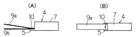
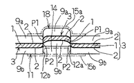
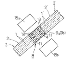
図1乃至図9は本発明に係るフラットケーブル接続部、その製造方法及びその製造装置の実施の形態の第1例を示したもので、図1はこの第1例のフラットケーブル接続部の斜視図、図2(A)(B)はこの第1例で用いている接続子の側面図及び平面図、図3はこの第1例のフラットケーブル接続部の平面図、図4はこの第1例で用いるフラットケーブル接続部の製造装置の要部構成を示した斜視図、図5は図3のA1 −A1 線断面図、図6は図3のB1 −B1 線端面図、図7は図3のC1 −C1 線端面図、図8は図6に表示された段違い部分の凹部に形状維持手段を介在させ且つこの段違い部分に絶縁被覆を被せた状態を示す端面図、図9は図7に表示された段違い部分の凹部に形状維持手段を介在させ且つこの段違い部分に絶縁被覆を被せた状態を示す端面図である。
【0079】
この第1例のフラットケーブル接続部8では、接続子4として、図2(A)(B)に示すように、雌形の接続継ぎ手7に一体の端子板5に、厚さが0.25mm程度の銅シートやアルミシート等よりなる2枚の導電シート9a,9bの基端が重ねられて接続点10で超音波溶接等で圧着されて相互に電気的につながり且つ機械的に固定された構造のものが用いられている。
【0080】
このフラットケーブル接続部8では、フラット導体1がフラット絶縁被覆2で覆われているフラットケーブル3に、接続子4の端子板5に電気的につながった2枚の導電シート9a,9bがフラット導体1の箇所を挟むように重ね合されて重ね合せ部11が形成されている。この場合、接続子4の接続継ぎ手7はフラットケーブル3の長手方向に向けて該フラットケーブル3の端部に配置されている。重ね合せ部11には、フラット導体1の箇所で2条の切れ目12a,12bが相互にほぼ平行に入れられている。この2条の切れ目12a,12bの間の部分13がその幅方向の両側の部分に対して重ね合せ部11の積層方向に段違いにされ、各切れ目12a,12bに沿った部分の両端の部分に、図7に示すようにフラット導体1と導電シート9a,9bが接触した接触部P1 ,P2 がそれぞれ設けられている。
【0081】
かかる状態で、このようなフラットケーブル接続部8の重ね合せ部11の段違い部分の凹部内に、必要に応じて、その段違い形状を維持させるプラスチックピースの如き固形ブロック等よりなる形状維持手段14が介在させて設けられている。また、この状態で段違い部分の表面と裏面には、片面に接着剤を積層した絶縁シートよりなる絶縁被覆15a,15bが接着されている。
【0082】
このような第1例のフラットケーブル接続部8の製造は、次のようにして行う。
フラットケーブル3に、接続子4の端子板5に電気的につながった2枚の導電シート9a,9bをフラット導体1の箇所を挟むように重ね合せて重ね合せ部11を形成する。この重ね合せ部11にフラット導体1の箇所で2条の切れ目12a,12bを相互にほぼ平行に入れる。2条の切れ目12a,12bの間の部分13をその幅方向の両側の部分に対して重ね合せ部11の積層方向に段違いにし、各切れ目12a,12bに沿った部分の両端の部分にフラット導体1と導電シート9a,9bが接触した接触部P1 ,P2 をそれぞれ設ける。
【0083】
このように重ね合せ部11に2条の切れ目12a,12bを相互にほぼ平行に入れ、2条の切れ目12a,12bの間の部分13をその幅方向の両側の部分に対して重ね合せ部11の積層方向に段違いにする作業は、例えば図4に示すように先端面にブリッジ状に凸形刃部16aを有する雄形の刃型17aと、この凸形刃部16aが嵌まり合う凹型刃部16bを先端面に有する雌形の刃型17bとを用いたフラットケーブル接続部の製造装置にて、フラット導体1の箇所で重ね合せ部11を上下からプレスすることにより一挙に能率よく行うことができる。即ち、雄形の刃型17aの凸形刃部16aと雌形の刃型17bの凹型刃部16bとで、重ね合せ部11をプレスすると、切れ目12a,12bの形成と、2条の切れ目12a,12bの間の部分13をその幅方向の両側の部分に対して重ね合せ部11の積層方向に段違いにする作業とを一挙に能率よく行うことができる。
【0084】
かかる状態で、このようなフラットケーブル接続部8の重ね合せ部11の段違い部分の凹部内に、必要に応じて、その段違い形状を維持させる形状維持手段14を介在させ、且つ段違い部分の表面と裏面に絶縁被覆15a,15bを接着させる。
【0085】
このようなフラットケーブル接続部8及びその製造方法は、高密度化されて、幅が狭く、厚みの薄いフラット導体1を用いたフラットケーブル3でも、その重ね合せ部11にフラット導体1の箇所で2条の切れ目12a,12bを入れ、この2条の切れ目12a,12bの間の部分13をその幅方向の両側の部分に対して重ね合せ部11の積層方向に段違いにするだけで容易に形成することができる。また、このフラットケーブル接続部8及びその製造方法では、クリンプ片を有する接続子を用いないので、幅が狭く、厚みの薄いフラット導体1が用いられていても、接続の信頼性の低下を招くことなく容易に形成することができる。
【0086】
また、重ね合せ部11の段違い部分の凹部内に、必要に応じて、その段違い形状を維持させる形状維持手段14を設けているので、段違い部分に加圧力が加わっても段違い形状がつぶれるのを防止でき、接続部の信頼性を向上させることができる。
【0087】
さらに、この重ね合せ部11の段違い部分を覆って絶縁被覆15a,15bを被せるので、段違い部分の絶縁を維持させることができる。
【0088】
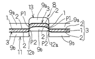
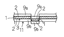
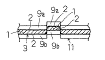
図10乃至図12は本発明に係るフラットケーブル接続部及びその製造方法の実施の形態の第2例を示したもので、図10はこの第2例のフラットケーブル接続部の平面図、図11は図10のB2 −B2 線端面図、図12は図10のC2 −C2 線端面図である。
【0089】
この第2例のフラットケーブル接続部8では、フラットケーブル3に、接続子4の端子板5に電気的につながった2枚の導電シート9a,9bがフラット導体1の箇所を挟むように重ね合されて重ね合せ部11が形成されている。この重ね合せ部11にフラット導体1の箇所で1条の切れ目12aが入れられている。この切れ目12aに直交する両側の部分が相対的に重ね合せ部11の積層方向に段違いにされ、切れ目12aに沿った部分の両端の部分にフラット導体1と導電シート9a,9bが接触した接触部P1 ,P2 が設けられている。
【0090】
かかる状態で、このようなフラットケーブル接続部8の重ね合せ部11の段違い部分の凹部内に、必要に応じて、その段違い形状を維持させるプラスチックピースの如き固形ブロック等よりなる形状維持手段14が介在させて設けられている。また、この状態で段違い部分の表面と裏面には、片面に接着剤を積層した絶縁シートよりなる絶縁被覆15a,15bが接着されている。
【0091】
このような第2例のフラットケーブル接続部8の製造は、次のようにして行う。フラットケーブル3に、接続子4の端子板5に電気的につながった2枚の導電シート9a,9bをフラット導体1の箇所を挟むように重ね合せて重ね合せ部11を形成する。この重ね合せ部11にフラット導体1の箇所で1条の切れ目12aを入れる。その切れ目12aに直交する両側の部分を相対的に重ね合せ部11の積層方向に段違いにし、切れ目12aに沿った部分の両端の部分にフラット導体1と導電シート9a,9bが接触した接触部P1 ,P2 を設ける。
【0092】
かかる状態で、このようなフラットケーブル接続部8の重ね合せ部11の段違い部分の凹部内に形状維持手段14を介在させる。また、この状態で段違い部分の表面と裏面には、片面に接着剤を積層した絶縁シートよりなる絶縁被覆15a,15bを接着する。
【0093】
このようなフラットケーブル接続部8及びその製造方法は、高密度化されて、幅が狭く、厚みの薄いフラット導体1を用いたフラットケーブル3でも、その重ね合せ部11にフラット導体の箇所で1条の切れ目12aを入れ、その切れ目12aに直交する両側の部分を相対的に重ね合せ部11の積層方向に段違いにするだけで容易に形成することができる。また、このフラットケーブル接続部8及びその製造方法では、クリンプ片を有する接続子を用いないので、幅が狭く、厚みの薄いフラット導体1が用いられていても、接続の信頼性の低下を招くことなく容易に形成することができる。
【0094】
また、重ね合せ部11の段違い部分の凹部内に、必要に応じて、その段違い形状を維持させる形状維持手段14を設けているので、段違い部分に加圧力が加わっても段違い形状がつぶれるのを防止でき、接続部の信頼性を向上させることができる。
【0095】
さらに、この重ね合せ部11の段違い部分を覆って絶縁被覆15a,15bを被せるので、段違い部分の絶縁を維持させることができる。
【0096】
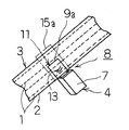
図13乃至図15は本発明に係るフラットケーブル接続部及びその製造方法の実施の形態の第3例を示したもので、図13はこの第3例のフラットケーブル接続部の平面図、図14は図13のB3 −B3 線端面図、図15は図13のC3 −C3 線端面図である。
【0097】
この第3例のフラットケーブル接続部8では、フラットケーブル3に、接続子4の端子板5に電気的につながった2枚の導電シート9a,9bがフラット導体1の箇所を挟むように重ね合されて重ね合せ部11が形成されている。この重ね合せ部11にフラット導体1の箇所でコ字状(或いはU字状)の切れ目12が入れられて舌片18が形成されている。この舌片18とこれに隣接する重ね合せ部11の部分が重ね合せ部11の積層方向に段違いにされ、舌片18の基端の部分の両側にフラット導体1と導電シート9a,9bが接触した接触部P1 ,P2 がそれぞれ設けられている。
【0098】
かかる状態で、このようなフラットケーブル接続部8の重ね合せ部11の段違い部分の凹部内に、必要に応じて、その段違い形状を維持させるプラスチックピースの如き固形ブロック等よりなる形状維持手段14が介在させて設けられている。また、この状態で段違い部分の表面と裏面には、片面に接着剤を積層した絶縁シートよりなる絶縁被覆15a,15bが接着されている。
【0099】
このような第3例のフラットケーブル接続部8の製造は、次のようにして行う。フラットケーブル3に、接続子4の端子板5に電気的につながった2枚の導電シート9a,9bをフラット導体1の箇所を挟むように重ね合せて重ね合せ部11を形成する。この重ね合せ部11にフラット導体1の箇所でコ字状或いはU字状の切れ目12を入れて舌片18を形成する。この舌片18とこれに隣接する重ね合せ部11の部分を重ね合せ部11の積層方向に段違いにし、舌片18の基端の部分の両側にフラット導体1と導電シート9a,9bが接触した接触部P1 ,P2 をそれぞれ設ける。
【0100】
かかる状態で、このようなフラットケーブル接続部8の重ね合せ部11の段違い部分の凹部内に形状維持手段14を介在させる。また、この状態で段違い部分の表面と裏面には、片面に接着剤を積層した絶縁シートよりなる絶縁被覆15a,15bを接着する。
【0101】
上記例では、重ね合せ部11にコ字状(或いはU字状)の切れ目12を入れて舌片18を構成したが、本発明はこれに限定されるものではなく、V状の切れ目12を入れて舌片18を構成することもできる。
【0102】
このようなフラットケーブル接続部8及びその製造方法は、高密度化されて、幅が狭く、厚みの薄いフラット導体1を用いたフラットケーブル3でも、その重ね合せ部11にフラット導体1の箇所でコ字状またはV字状の切れ目12を入れて舌片18を形成し、この舌片18とこれに隣接する重ね合せ部11の部分を重ね合せ部11の積層方向に段違いにするだけで容易に形成することができる。また、このフラットケーブル接続部8及びその製造方法では、クリンプ片を有する接続子を用いないので、幅が狭く、厚みの薄いフラット導体1が用いられていても、接続の信頼性の低下を招くことなく容易に形成することができる。
【0103】
また、重ね合せ部11の段違い部分の凹部内に、必要に応じて、その段違い形状を維持させる形状維持手段14を設けているので、段違い部分に加圧力が加わっても段違い形状がつぶれるのを防止でき、接続部の信頼性を向上させることができる。
【0104】
さらに、この重ね合せ部11の段違い部分を覆って絶縁被覆15a,15bを被せるので、段違い部分の絶縁を維持させることができる。
【0105】
図16は図1に示すフラットケーブル接続部8の変形例を示した斜視図である。この例では、接続子4の接続継ぎ手7をフラットケーブル3の長手方向に対して直交する向きでフラットケーブル3の途中に配置して前述したようにフラットケーブル接続部8を形成した例を示したものである。
【0106】
上記各例では、接続子4として図2(A)(B)に示す構造のものを用いた例について説明したが、本発明はこれに限定されるものできなく、接続子4としては図17(A)(B)に示す構造のものを用いることができる。
【0107】
この接続子4では、1枚の導電シート9bに沿って且つ切れ目12,12a,12bを入れる部分を避けて補強片19が延長して設けられているものを用いることもできる。この補強片19には、切れ目12,12a,12bを入れる部分に窓20が貫通して開口されている。
【0108】
このような構造の接続子4を用いて、前述した第1例〜第3例のフラットケーブル接続部8を構成すると、補強片19によりこのフラットケーブル接続部8の部分が曲がり難くなり、接続部8の信頼性を向上させることができる。
【0109】
なお、図10〜図12に示すタイプのフラットケーブル接続部8や、図13〜図15に示すタイプのフラットケーブル接続部8も、それに応じて凸形刃部16aと凹型刃部16bの形状を変更した雄形の刃型17aと雌形の刃型17bとを用いたフラットケーブル接続部の接続装置で、前述したと同様にして一挙に形成することができる。
【0110】
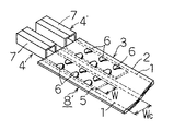
図18は本発明に係るフラットケーブル接続部及びその製造方法の第4例を示した斜視図である。
【0111】
この第4例のフラットケーブル接続部8では、フラットケーブル3に、接続子4を構成する電気的につながった2枚の導電シート9a,9bがフラット導体1の箇所を挟むように重ね合されて重ね合せ部11が形成されている。重ね合せ部11には、第1例と同様に、フラット導体1の箇所で2条の切れ目12a,12bが相互にほぼ平行に入れられている。この2条の切れ目12a,12bの間の部分13がその幅方向の両側の部分に対して重ね合せ部11の積層方向に段違いにされ、各切れ目12a,12bに沿った部分の両端の部分に、前述した図7と同様にフラット導体1と導電シート9a,9bが接触した接触部P1 ,P2 がそれぞれ設けられている。
【0112】
このようなフラットケーブル接続部8は、電気的につながった2枚の導電シート9a,9bによって短絡接続する複数のフラット導体1に対して形成されている。
【0113】
かかる状態で、このようなフラットケーブル接続部8の重ね合せ部11の段違い部分の凹部内に、必要に応じて、図示しないが、その段違い形状を維持させるプラスチックピースの如き固形ブロック等よりなる形状維持手段14が介在させて設けられている。また、この状態で段違い部分の表面と裏面には、図示しないが、片面に接着剤を積層した絶縁シートよりなる絶縁被覆15a,15bが接着されている。
【0114】
このような第4例のフラットケーブル接続部8の製造は、次のようにして行う。フラットケーブル3に、接続子4を構成する電気的につながった2枚の導電シート9a,9bをフラット導体1の箇所を挟むように重ね合せて重ね合せ部11を形成する。この重ね合せ部11にフラット導体1の箇所で2条の切れ目12a,12bを相互にほぼ平行に入れる。2条の切れ目12a,12bの間の部分13をその幅方向の両側の部分に対して重ね合せ部11の積層方向に段違いにし、各切れ目12a,12bに沿った部分の両端の部分にフラット導体1と導電シート9a,9bが接触した接触部P1 ,P2 をそれぞれ設ける。
【0115】
このようなフラットケーブル接続部8の形成を、導電シート9a,9bによって相互に短絡接続すべき複数のフラット導体1に対して行う。
【0116】
かかる状態で、このようなフラットケーブル接続部8の重ね合せ部11の段違い部分の凹部内に、必要に応じて、図示しないが、その段違い形状を維持させるプラスチックピースの如き固形ブロック等よりなる形状維持手段14を介在させて設けられて設ける。また、この状態で段違い部分の表面と裏面には、図示しないが、片面に接着剤を積層した絶縁シートよりなる絶縁被覆15a,15bを接着する。
【0117】
この例では、接続子4は接続継ぎ手7を有しないものが用いられている。2枚の導電シート9a,9bは、例えば1枚の導電シートを2つ折りにして2枚の導電シート9a,9bを得、その折り目の部分を導電シート9a,9bの電気的つながり部分として用いることもできる。
【0118】
このようなフラットケーブル接続部及びその製造方法によれば、フラットケーブル3の任意の位置で複数のフラット導体1の短絡接続を行うことができる。その他の効果は、第1例と同様である。
【0119】
このようなフラットケーブル3と導電シート9a,9bの重ね合せ部11で形成したフラットケーブル接続部8は、図10〜図12に示すタイプでも、図13〜図15に示すタイプでも、形成することができ、各タイプの効果を得ることができる。
【0120】
図19は本発明に係るフラットケーブル接続部及びその製造方法の第5例を示した斜視図である。
【0121】
本例のフラットケーブル接続部8では、フラット導体1,1´がフラット絶縁被覆2,2´で覆われている2条のフラットケーブル3,3´が、相互のフラット導体1,1´が交差するように交差状態に重ね合されて重ね合せ部分が形成されている。かかる状態で、接続子4を構成する電気的につながった2枚の導電シート9a,9bが前述した重ね合せ部分を挟み込むように重ね合されて重ね合せ部11が形成されている。相互のフラット導体1,1´の交差部で重ね合せ部11に、前述したと同様に2条の切れ目12a,12bが相互にほぼ平行に入れられている。これら2条の切れ目12a,12bの間の部分13がその幅方向の両側の部分に対して重ね合せ部11の積層方向に段違いにされ、前述したと同様に各切れ目12a,12bに沿った部分の両端の部分にフラット導体1と導電シート9a,9bが接触した接触部P1 ,P2 がそれぞれ設けられている。
【0122】
かかる状態で、図示しないが前述したと同様に、フラットケーブル接続部8の重ね合せ部11の段違い部分の凹部内に、必要に応じて、その段違い形状を維持させるプラスチックピースの如き固形ブロック等よりなる形状維持手段14が介在させて設けられている。また、図示しないが前述したと同様に、この状態で段違い部分の表面と裏面には、片面に接着剤を積層した絶縁シートよりなる絶縁被覆15a,15bが接着されている。
【0123】
この例でも、接続子4は接続継ぎ手7を有しないものが用いられている。2枚の導電シート9a,9bは、例えば1枚の導電シートを2つ折りにして2枚の導電シート9a,9bを得、その折り目の部分(基端部)を導電シート9a,9bの電気的つながり部分として用いることもできる。
【0124】
このような第5例のフラットケーブル接続部8の製造は、次のようにして行う。2条のフラットケーブル3,3´を、相互のフラット導体1,1´が交差するように交差状態に重ね合せて重ね合せ部分を形成する。接続子4を構成する電気的につながった2枚の導電シート9a,9bを、前述した重ね合せ部分を挟み込むように重ね合せて重ね合せ部11を形成する。相互のフラット導体1,1´の交差部で重ね合せ部11に2条の切れ目12a,12bを相互にほぼ平行に入れる。
【0125】
この2条の切れ目12a,12bの間の部分13をその幅方向の両側の部分に対して重ね合せ部11の積層方向に段違いにし、各切れ目12a,12bに沿った部分の両端の部分にフラット導体1,1´と導電シート9a,9bが接触した接触部P1 ,P2 をそれぞれ設ける。
【0126】
かかる状態で、このようなフラットケーブル接続部8の重ね合せ部11の段違い部分の凹部内に、必要に応じて、その段違い形状を維持させる形状維持手段14を介在させ、且つ段違い部分の表面と裏面に絶縁被覆15a,15bを接着させる。
【0127】
このようなフラットケーブル接続部8及びその製造方法は、高密度化されて、幅が狭く、厚みの薄いフラット導体1,1´を用いたフラットケーブル3,3´でも、その重ね合せ部11にフラット導体1,1´の箇所で2条の切れ目12a,12bを入れ、この2条の切れ目12a,12bの間の部分13をその幅方向の両側の部分に対して重ね合せ部11の積層方向に段違いにするだけで容易に形成することができる。また、このフラットケーブル接続部8及びその製造方法では、クリンプ片を有する接続子を用いないので、幅が狭く、厚みの薄いフラット導体1,1´が用いられていても、接続の信頼性の低下を招くことなく容易に形成することができる。
【0128】
このようなフラットケーブル3,3´の重ね合せ部11で形成したフラットケーブル接続部8は、図10〜図12に示すタイプでも、図13〜図15に示すタイプでも、形成することができ、各タイプの効果を得ることができる。
【0129】
図20は本発明に係るフラットケーブル接続部及びその製造方法の第6例を示した斜視図である。
【0130】
本例のフラットケーブル接続部8では、フラット導体1,1´がフラット絶縁被覆2,2´で覆われている2条のフラットケーブル3,3´が、その端部を向かい合わせて配置されている。これらフラットケーブル3,3´の端部の向かい合わせ部分に跨がって、接続子4を構成する電気的につながった2枚の導電シート9a,9bが両側のフラットケーブル3,3´の端部を挟み込むように重ね合されて重ね合せ部11がそれぞれ形成されている。各側の重ね合せ部11にフラット導体1,1´の箇所で、前述したと同様に2条の切れ目12a,12bが相互にほぼ平行に入れられている。これら2条の切れ目12a,12bの間の部分13がその幅方向の両側の部分に対して重ね合せ部11の積層方向に段違いにされ、前述したと同様に各切れ目12a,12bに沿った部分の両端の部分にフラット導体1,1´と導電シート9a,9bが接触した接触部P1 ,P2 がそれぞれ設けられている。
【0131】
かかる状態で、図示しないが前述したと同様に、フラットケーブル接続部8の重ね合せ部11の段違い部分の凹部内に、必要に応じて、その段違い形状を維持させるプラスチックピースの如き固形ブロック等よりなる形状維持手段14が介在させて設けられている。また、図示しないが前述したと同様に、この状態で段違い部分の表面と裏面には、片面に接着剤を積層した絶縁シートよりなる絶縁被覆15a,15bが接着されている。
【0132】
この例でも、接続子4は接続継ぎ手7を有しないものが用いられている。2枚の導電シート9a,9bは、前述したように、例えば1枚の導電シートを2つ折りにして2枚の導電シート9a,9bを得、その折り目の部分(基端部)を導電シート9a,9bの電気的つながり部分として用いることもできる。
【0133】
このような第6例のフラットケーブル接続部8の製造は、次のようにして行う。2条のフラットケーブル3,3´を、その端部を向かい合わせて配置する。これらフラットケーブル3,3´の端部の向かい合わせ部分に跨がって、接続子4を構成する電気的につながった2枚の導電シート9a,9bを両側のフラットケーブル3,3´の端部を挟み込むように重ね合せて重ね合せ部11をそれぞれ形成し、各側の重ね合せ部11にフラット導体1,1´の箇所で2条の切れ目12a,12bを相互にほぼ平行に入れる。この2条の切れ目12a,12bの間の部分13をその幅方向の両側の部分に対して重ね合せ部11の積層方向に段違いにし、各切れ目12a,12bに沿った部分の両端の部分にフラット導体1,1´と導電シート9a,9bが接触した接触部P1 ,P2 をそれぞれ設ける。
【0134】
かかる状態で、このようなフラットケーブル接続部8の重ね合せ部11の段違い部分の凹部内に、必要に応じて、その段違い形状を維持させる形状維持手段14を介在させ、且つ段違い部分の表面と裏面に絶縁被覆15a,15bを接着させる。
【0135】
このようなフラットケーブル接続部8及びその製造方法は、高密度化されて、幅が狭く、厚みの薄いフラット導体1,1´を用いたフラットケーブル3,3´でも、その重ね合せ部11にフラット導体1,1´の箇所で2条の切れ目12a,12bを入れ、この2条の切れ目12a,12bの間の部分13をその幅方向の両側の部分に対して重ね合せ部11の積層方向に段違いにするだけで容易に形成することができる。また、このフラットケーブル接続部8及びその製造方法では、クリンプ片を有する接続子を用いないので、幅が狭く、厚みの薄いフラット導体1,1´が用いられていても、接続の信頼性の低下を招くことなく容易に形成することができる。
【0136】
このようなフラットケーブル3,3´の突合わせ端部の各重ね合せ部11で形成したフラットケーブル接続部8は、図10〜図12に示すタイプでも、図13〜図15に示すタイプでも、形成することができ、各タイプの効果を得ることができる。
【0137】
図21は本発明に係るフラットケーブル接続部及びその製造方法の第7例を示した斜視図である。
【0138】
本例のフラットケーブル接続部では、前述したと同様にフラット導体1がフラット絶縁被覆2で覆われているフラットケーブル3に、接続子4の電気的につながった2枚の導電シート9a,9bがフラット導体1の箇所を挟むように重ね合されて重ね合せ部11が形成されている。該重ね合せ部11にフラット導体1の箇所で3条の切れ目12a,12b,12cが相互にほぼ平行に入れられている。これら3条の切れ目12a,12b,12cの間の2つの部分13a,13bが、隣接相互間で突出方向を逆にして、即ち一方の部分13aは下側に凸、他方の部分13bは上側に凸として、これら2つの部分13a,13bの幅方向の両側の部分に対して重ね合せ部11の積層方向に段違いにされ、各切れ目12a,12b,12cに沿った部分の両端の部分にフラット導体1と導電シート9a,9bが接触した接触部がそれぞれ設けられている。
【0139】
このような構造のフラットケーブル接続部は、高密度化されて、幅が狭く、厚みの薄いフラット導体1を用いたフラットケーブル3でも、その重ね合せ部11にフラット導体1の箇所で3条の切れ目12a,12b,12cを入れ、この3条の切れ目12a,12b,12cの間の2つの部分13a,13bを隣接相互間で突出方向を逆にしてこれら2つの部分の幅方向の両側の部分に対して重ね合せ部の積層方向に段違いにするだけで容易に形成することができる。特に、このフラットケーブル接続部では、3条の切れ目12a,12b,12cを入れているので、接触部の数が増え、十分に導通をとることができる。また、このフラットケーブル接続部では、クリンプ片を有する接続子を用いないので、幅が狭く、厚みの薄いフラット導体1が用いられていても、接続の信頼性の低下を招くことなく容易に形成することができる。
【0140】
図22〜図24は本発明に係るフラットケーブル接続部及びその製造方法の第8例を示したもので、図22は本例のフラットケーブル接続部の縦断面図、図23は図22のD−D線断面図、図24は図22のE−E線断面図である。
【0141】
本例のフラットケーブル接続部8では、フラット導体1がフラット絶縁被覆2で覆われているフラットケーブル3に、接続子4の電気的につながった2枚の導電シート9a,9bがフラット導体1の箇所を挟むように重ね合されて重ね合せ部11が形成されている。該重ね合せ部11にフラット導体1の箇所で2条の切れ目12a,12bが相互にほぼ平行に入れられている。これら2条の切れ目12a,12bの間の部分13が切れ目12a,12bに沿って重ね合せ部11の積層方向に段違いにされている。この切れ目12a,12bに沿って重ね合せ部11の積層方向に段違いにされている部分は、本例では、切れ目12a,12bに沿った部分が重ね合せ部11の積層方向の一方側に凸で、次に中立位置に戻り、次に重ね合せ部11の積層方向の他方側に凸となる形状となっている。
【0142】
このような構成になっていると、切れ目12a,12bの間の部分13の凸部にこれを押圧する力が作用した場合、隣り合う反対方向に突出する凸部の存在により、押圧された凸部がつぶれるのを防止することができる。
【0143】
次に、図4に示したフラットケーブル接続部の製造装置について、図25(A)(B)乃至図27を参照してさらに説明する。図25(A)(B)は重ね合せ部11を雄形の刃型17aと雌形の刃型17bとでプレスする前と、プレスした後の状態における該フラットケーブル接続部の製造装置の要部縦断面図、図26は隙間の値が本発明の範囲より小さい場合における図3のC1 −C1 線端面図、図27は隙間の値が本発明の範囲より大きい場合における図3のC1 −C1 線端面図である。
【0144】
このフラットケーブル接続部の製造装置は、先端面にブリッジ状に幅Wtの凸形刃部16aを有する雄形の刃型17aと、この凸形刃部16aが嵌まり合う幅Woの凹型刃部16bを先端面に有する雌形の刃型17bとを備え、雄形の刃型17aはガイド部材21でガイドされて凸形刃部16aが凹型刃部16bに嵌まり合うようになっている。
【0145】
この雄形の刃型17aと雌形の刃型17bとの間に、厚さtのフラット導体1をフラット絶縁被覆2で覆ったフラットケーブル3の両面に導電シート9a,9bを重ねた重ね合せ部11を配置する。
【0146】
かかる状態で、重ね合せ部11のフラット導体1の存在箇所を雄形の刃型17aと雌形の刃型17bでプレスし、凸形刃部16aが凹型刃部16bに嵌まり合うようにする。
【0147】
この動作で、フラット導体1の存在箇所で重ね合せ部11の2箇所が剪断されて2条の切れ目12a,12bが平行に入り、これら2条の切れ目12a,12bの間の部分13が図25(A)(B)の例では下方に突き出されて、この2条の切れ目12a,12bの間の部分13がその幅方向の両側の部分に対して重ね合せ部11の積層方向に段違いにされる。
【0148】
凸形刃部16aが凹型刃部16bに嵌まり合った状態で、凹型刃部16bの幅Woと、凸形刃部16aの幅Wtとの差の半分が隙間g=(Wo−Wt)/2として存在している。
【0149】
この際に、切れ目12a,12bで剪断されて伸ばされたフラット導体1が丁度剪断された導電シート9a,9bの間に挟み込まれるようにフラット導体1と導電シート9a,9bとのずれ面が接触部P1 ,P2 で接触することで安定した接触が得られる。なお、フラット導体1を覆っているフラット絶縁被覆2は、伸び率が低いので、フラット導体1が剪断を始める時には既に伸び切れていて、フラット導体1と導電シート9a,9bとの電気的接触に問題を生じさせない。
【0150】
この性質を確認するため、図25(B)の隙間gを変えて、フラット導体1の厚さt=0.035 mm、0.06mm、導電シート9a,9bの厚さ0.25mmの条件で圧着実験を行ったところ、隙間gがフラット導体1の厚さtの0.4 〜1.0 倍のときにフラット導体1のずれ面が導電シート9a,9bに挟み込まれる現象が起き、安定した電気的接触状態が得られることが判った。
【0151】
隙間gの値がこの範囲より小さい場合には、図3のC1 −C1 線端面図が図26に示すようになって、フラット導体1は鋭く剪断されて導電シート9a,9bとの接触は弱くなり、図7に示すようにフラット導体1が切れ目12a,12bで導電シート9a,9bに挟み込まれた状態に比べると、フラット導体1と導電シート9a,9bとの重なりが剥れ易くなっている。
【0152】
また、隙間gの値が上述の範囲より大きい場合には、図3のC1 −C1 線端面図が図27に示すようになって、導電シート9a,9bが重ねられたフラットケーブル3が剪断される前に間の部分13が押し込まれる状態になり、フラット導体1と導電シート9a,9bとが接触し難い状態になってしまう。
【0153】
最後に、雄形の刃型17aを雌形の刃型17bに対して上方に退避させて切断とずらしによる接続作業を完了する。
【0154】
なお、本発明のフラットケーブル接続部8は、図3に示す切れ目12a,12bによる間の部分13を、図3で重ね合せ部11の長手方向に隣接させて2箇所に設け、例えば一方の間の部分13を上に凸にずらし、他方の間の部分13を下に凸にずらして形成することもできる。
【0155】
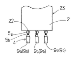
図28は、接続端子4のさらに他の例を示したものである。本例の接続端子4は、端子板5の先端に2枚の導電シート9a,9bが電気的・機械的に接続され端子板5の基端にインシュレーションバレル部5aとワイヤーバレル部5bとが設けられた構造になっている。これらインシュレーションバレル部5aとワイヤーバレル部5bとに、丸形絶縁電線22の絶縁被覆22aとワイヤー導体22bとが把持されて接続されている。
【0156】
このような接続端子4の導電シート9a,9bを用いて前述したようにフラットケーブル3のフラット導体1に接続し、フラットケーブル3のフラット導体1と丸形絶縁電線22のワイヤー導体22bとを電気的・機械的に接続することができる。即ち、この接続端子4によれば、フラットケーブル3と丸形絶縁電線22の接続を行うことができる。
【0157】
図29は、丸線フラットケーブル23のフラット絶縁被覆2で被覆された各丸形絶縁電線22の各露出端に、図28に示したように接続端子4をそれぞれ接続した構造を示したものである。
【0158】
このような丸線フラットケーブル23を用いれば、丸形絶縁電線22の丸線フラットケーブル23とフラット導体1のフラットケーブル3との接続を行うことができる。
【0159】
【発明の効果】
本発明に係るフラットケーブル接続部及びその製造方法では、高密度化されて、幅が狭く、厚みの薄いフラット導体を用いたフラットケーブルでも、その重ね合せ部にフラット導体の箇所で1条の切れ目を入れ、その切れ目に直交する両側の部分を相対的に重ね合せ部の積層方向に段違いにするだけで容易に形成することができる。また、このフラットケーブル接続部及びその製造方法では、クリンプ片を有する接続子を用いないので、幅が狭く、厚みの薄いフラット導体が用いられていても、接続の信頼性の低下を招くことなく容易に形成することができる。
【0160】
また、本発明に係るフラットケーブル接続部及びその製造方法では、高密度化されて、幅が狭く、厚みの薄いフラット導体を用いたフラットケーブルでも、その重ね合せ部にフラット導体の箇所で2条の切れ目を入れ、この2条の切れ目の間の部分をその幅方向の両側の部分に対して重ね合せ部の積層方向に段違いにするだけで容易に形成することができる。また、このフラットケーブル接続部及びその製造方法では、クリンプ片を有する接続子を用いないので、幅が狭く、厚みの薄いフラット導体が用いられていても、接続の信頼性の低下を招くことなく容易に形成することができる。
【0161】
また、本発明に係るフラットケーブル接続部及びその製造方法では、高密度化されて、幅が狭く、厚みの薄いフラット導体を用いたフラットケーブルでも、その重ね合せ部にフラット導体の箇所で3条の切れ目を入れ、この3条の切れ目の間の2つの部分を隣接相互間で突出方向を逆にしてこれら2つの部分の幅方向の両側の部分に対して重ね合せ部の積層方向に段違いにするだけで容易に形成することができる。特に、このフラットケーブル接続部及びその製造方法では、3条の切れ目を入れているので、接触部の数が増え、十分に導通をとることができる。また、このフラットケーブル接続部の製造方法では、クリンプ片を有する接続子を用いないので、幅が狭く、厚みの薄いフラット導体が用いられていても、接続の信頼性の低下を招くことなく容易に形成することができる。
【0162】
さらに、本発明に係るフラットケーブル接続部の製造装置では、先端面に凸形刃部を有する雄形の刃型と、該凸形刃部が嵌まり合う凹型刃部を先端面に有する雌形の刃型とを用いるので、フラットケーブルと導電シートとが重なり合った重ね合せ部に、フラットケーブルのフラット導体の箇所で切れ目を入れ、この切れ目に直交する両側の部分を重ね合せ部の積層方向に段違いにする作業を一挙に能率よく行うことができる。
【図面の簡単な説明】
【図1】 本発明に係るフラットケーブル接続部の実施の形態の第1例を示した斜視図である。
【図2】 (A)(B)はこの第1例で用いている接続子の側面図及び平面図である。
【図3】 この第1例のフラットケーブル接続部の平面図である。
【図4】 この第1例で用いている刃型の斜視図である。
【図5】 図3のA1 −A1 線断面図である。
【図6】 図3のB1 −B1 線端面図である。
【図7】 図3のC1 −C1 線端面図である。
【図8】 図6に表示された段違い部分の凹部に形状維持手段を介在させ且つこの段違い部分に絶縁被覆を被せた状態を示す端面図である。
【図9】 図7に表示された段違い部分の凹部に形状維持手段を介在させ且つこの段違い部分に絶縁被覆を被せた状態を示す端面図である。
【図10】 本発明に係るフラットケーブル接続部の実施の形態の第2例を示した平面図である。
【図11】 図10のB2 −B2 線端面図である。
【図12】 図10のC2 −C2 線端面図である。
【図13】 本発明に係るフラットケーブル接続部の実施の形態の第3例を示した平面図である。
【図14】 図13のB3 −B3 線端面図である。
【図15】 図13のC3 −C3 線端面図である。
【図16】 図1に示すフラットケーブル接続部8の変形例を示した斜視図である。
【図17】 (A)(B)は接続子の他の例の側面図及び平面図である。
【図18】 本発明に係るフラットケーブル接続部及びその製造方法の第4例を示した斜視図である。
【図19】 本発明に係るフラットケーブル接続部及びその製造方法の第5例を示した斜視図である。
【図20】 本発明に係るフラットケーブル接続部及びその製造方法の第6例を示した斜視図である。
【図21】 本発明に係るフラットケーブル接続部及びその製造方法の第7例を示した斜視図である。
【図22】 本発明に係るフラットケーブル接続部及びその製造方法の第8例を示した縦断面図である。
【図23】 図22のD−D線断面図である。
【図24】 図22のE−E線断面図である。
【図25】 (A)(B)は本発明の第1例で重ね合せ部を雄形の刃型と雌形の刃型とでプレスする前と、プレスした後の状態におけるフラットケーブル接続部の製造装置の要部縦断面図である。
【図26】 隙間の値が本発明の範囲より小さい場合における図3のC1 −C1 線端面図である。
【図27】 隙間の値が本発明の範囲より大きい場合における図3のC1 −C1 線端面図である。
【図28】 本発明で用いる接続端子の更に他の例として、丸形絶縁電線を接続した接続端子の例を示した斜視図である。
【図29】 本発明で用いる丸線フラットケーブルの例を示した斜視図である。
【図30】 従来のフラットケーブル接続部の接続前の状態を示す斜視図である。
【図31】 従来のフラットケーブル接続部の斜視図である。
【符号の説明】
1,1´ フラット導体
2,2´ フラット絶縁被覆
3,3´ フラットケーブル
4,4´ 接続子
5 端子板
6 クリンプ片
7 接続継ぎ手
8,8´ フラットケーブル接続部
9a,9b 導電シート
10 接続点
11 重ね合せ部
12a,12b,12c 切れ目
13,13a,13b 間の部分
14 形状維持手段
15a,15b 絶縁被覆
16a 凸形刃部
16b 凹型刃部
17a 雄形の刃型
17b 雌形の刃型
18 舌片
19 補強片
20 窓
21 ガイド部材[0001]
BACKGROUND OF THE INVENTION
The present invention relates to a connecting portion of a flat cable used in electrical wiring of an electric device or an automobile, a manufacturing method thereof, and a manufacturing apparatus thereof.
[0002]
[Prior art]
As shown in FIG. 30, a
[0003]
In this case, the
[0004]
On the other hand, as the
[0005]
[Problems to be solved by the invention]
However, in recent years, the
[0006]
In this fine pitch
[0007]
Thus, the width of the
[0008]
An object of the present invention is to provide a flat cable connecting portion in which the reliability of the connecting portion is excellent even with a high-density flat cable and a method for manufacturing the same.
[0009]
Another object of the present invention is to provide a flat cable connecting portion and a method of manufacturing the same, which can further improve the reliability of the connecting portion even with a high-density flat cable.
[0010]
Another object of the present invention is to provide a flat cable connecting portion and a method for manufacturing the same, which can prevent the stepped portion from being crushed.
[0011]
Another object of the present invention is to provide a flat cable connecting portion capable of preventing the stepped portion from being crushed.
[0012]
Another object of the present invention is to provide a flat cable connecting portion capable of maintaining the insulation of the surface of the uneven portion.
[0013]
Another object of the present invention is to make a cut at the flat conductor portion of the flat cable in the overlapping portion where the flat cable and the conductive sheet overlap, and to place the portions on both sides perpendicular to the cut in the stacking direction of the overlapping portion. An object of the present invention is to provide a manufacturing method and a manufacturing apparatus for a flat cable connecting portion capable of performing the steps of making the steps at once.
[0014]
Another object of the present invention is to provide a manufacturing method and a manufacturing apparatus of a flat cable connecting portion that can stabilize electrical and mechanical connection between a flat conductor and a conductive sheet.
[0015]
[Means for Solving the Problems]
Flat cable connector according to the present inventionIn one aspect, there is provided a connector having a structure in which two conductive sheets are superposed and the base ends of the two conductive sheets are electrically and mechanically connected. Further, a flat cable formed by covering a flat conductor with a flat insulating coating is sandwiched between two conductive sheets of the connector to form an overlapping portion in which the two conductive sheets and the flat cable are overlapped. The Then, a single cut that penetrates the two conductive sheets of the connector and the flat insulating coating and the flat conductor sandwiched between the two conductive sheets of the flat cable is put in the overlapping portion. AndThe portions on both sides orthogonal to the cut are relatively stepped in the stacking direction of the overlapping portion, and the contact portion where the flat conductor and the conductive sheet are in contact with the both ends of the portion along the cut is provided.Each is formed.
[0016]
Flat cable connection part of such structureAccording toEven in a flat cable using a flat conductor with a high density and a narrow width and a thin thickness, a single cut is made at the location of the flat conductor in the overlapping portion, and the portions on both sides orthogonal to the cut are relative to each other. In addition, it can be easily formed by simply making a difference in the stacking direction of the overlapping portion. In addition, since the flat cable connecting portion does not use a connector having a crimp piece, even if a flat conductor having a small width and a small thickness is used, it is easily formed without causing a decrease in connection reliability. be able to.
[0017]
Moreover, the flat cable connection portion according to the present inventionIn other embodiments,A connector having two conductive sheets stacked and having a structure in which base ends of the two conductive sheets are electrically and mechanically connected is provided, and the flat conductor is covered with a flat insulating coating. The flat cable is sandwiched between the two conductive sheets of the connector to form an overlapping portion in which the two conductive sheets and the flat cable are overlapped. Then, the two cuts that penetrate the two conductive sheets of the connector and the flat insulating coating and the flat conductor sandwiched between the two conductive sheets of the flat cable are almost parallel to the overlapping portion. Put inThe portion between the two cuts is stepped in the stacking direction of the overlapping portion with respect to the both sides in the width direction, and the flat conductor and the conductive sheet are in contact with both ends of the portion along each cut PartEach is formed.
[0018]
Flat cable connection part of such structureAccording toEven in a flat cable using a flat conductor with a high density, a narrow width, and a thin thickness, two cuts are made at the place of the flat conductor in the overlapping portion, and the portion between the two cuts is It can be easily formed only by making a difference in the stacking direction of the overlapping portion with respect to the portions on both sides in the width direction. In addition, since the flat cable connecting portion does not use a connector having a crimp piece, even if a flat conductor having a small width and a small thickness is used, it is easily formed without causing a decrease in connection reliability. be able to.
[0019]
Moreover, the flat cable connection part which concerns on this inventionIn yet another aspect of,A connector having a structure in which two conductive sheets are superposed and the base ends of the two conductive sheets are electrically and mechanically connected is provided, and the flat conductor is covered with a flat insulating coating. The flat cable formed is sandwiched between two conductive sheets to form an overlapping portion in which the two conductive sheets and the flat cable are overlapped. The three cuts that penetrate the two conductive sheets of the connector and the flat insulating coating and the flat conductor sandwiched between the two conductive sheets of the flat cable are almost parallel to the overlapping portion. Put inTwo portions between the three cuts are stepped in the stacking direction of the overlapping portion with respect to the portions on both sides in the width direction of the two portions with the protruding directions reversed between adjacent ones. The contact part where the flat conductor and the conductive sheet contact each otherIt is formed.
[0020]
When the flat cable connection is configured as described above,Even in a flat cable using a flat conductor with a high density, a narrow width, and a thin thickness, the section of the flat conductor is cut at the overlapped portion of the flat cable, and two portions between the three cuts are formed. Can be easily formed by making the protruding direction between adjacent ones opposite to each other in the stacking direction of the overlapping portion with respect to the portions on both sides in the width direction of these two portions. In particular, since this flat cable connecting portion has three cuts, the number of contact portions is increased and sufficient conduction can be obtained. In addition, since the flat cable connecting portion does not use a connector having a crimp piece, even if a flat conductor having a small width and a small thickness is used, it is easily formed without causing a decrease in connection reliability. be able to.
[0021]
Further, in the flat cable connecting portion according to the present invention as described above, the portion that is stepped in the stacking direction of the overlapping portion along the cut line is the portion along the cut line on one side in the stacking direction of the overlapping portion. It is preferable that it is convex and then returns to the neutral position and then convex to the other side in the stacking direction of the overlapping portion.
[0022]
If it has such composition, when the force which presses this will act on a convex part, it can prevent that a pressed convex part is crushed by existence of a convex part which protrudes in the adjacent opposite direction. .
[0023]
Also, the flat cable according to the present inventionIn another aspect of the connecting portion, there is provided a connector having a structure in which two conductive sheets are superposed and the base end portions of the two conductive sheets are electrically and mechanically connected, A flat cable formed by covering a flat conductor with a flat insulating coating is sandwiched between two conductive sheets to form an overlapping portion in which the two conductive sheets and the flat cable are overlapped. A U-shaped or V-shaped cut through the conductive sheet and the flat insulating coating and the flat conductor sandwiched between the two conductive sheets of the flat cable is put in the overlapping portion. A tongue piece is formed. Also thisThe tongue portion and the overlapping portion adjacent to the tongue portion are stepped in the stacking direction of the overlapping portion, and the contact portions where the flat conductor and the conductive sheet are in contact with both sides of the base end portion of the tongue piece respectively.It is formed.
[0024]
When the flat cable connection is configured as aboveEven with flat cables with high density, narrow width, and thin flat conductor, U-shaped or V-shaped cuts are made at the location of the flat conductor in the overlapping part to form tongue pieces The tongue piece and the portion of the overlapping portion adjacent to the tongue piece can be easily formed only by making a difference in the stacking direction of the overlapping portion. In addition, since the flat cable connecting portion does not use a connector having a crimp piece, even if a flat conductor having a small width and a small thickness is used, it is easily formed without causing a decrease in connection reliability. be able to.
[0025]
Moreover, in the flat cable connecting portion according to the present invention,The connector is provided with a reinforcing piece that extends along one of the two conductive sheets, avoiding the cut portion.It is preferable.
[0026]
In the flat cable connecting portion having such a structure, the portion of the flat cable connecting portion is hardly bent by the reinforcing piece, and the reliability of the connecting portion can be improved.
[0027]
Moreover, the flat cable connection part which concerns on this inventionIn another aspect, there is provided a connector having a structure in which two conductive sheets are superposed and the base end portions of the two conductive sheets are electrically and mechanically connected, and the flat conductor is provided. Two strips with a structure covered with a flat insulation coating The rat cables are overlapped in a crossed state, and the crossed and overlapped portions of the two flat cables are sandwiched between two conductive sheets constituting the connector. As a result, an overlapping portion of the two conductive sheets and the intersecting portion of the two flat cables is formed. Further, two conductive sheets of the connector and a single cut through the flat insulating coating and the flat conductor at the intersecting portion of the two flat cables sandwiched between the two conductive sheets overlap. Put in the mating section,The portions on both sides orthogonal to the cut are relatively stepped in the stacking direction of the overlapping portion, and the contact portion where the flat conductor and the conductive sheet are in contact with the both ends of the portion along the cut is provided.It is formed.
[0028]
When the flat cable connection is configured as described above,Even in a flat cable using a flat conductor with a high density and a narrow width and a thin thickness, a single cut is made at the location of the flat conductor in the overlapping portion, and the portions on both sides orthogonal to the cut are relative to each other. In addition, it can be easily formed by simply making a difference in the stacking direction of the overlapping portion. In addition, since the flat cable connecting portion does not use a connector having a crimp piece, even if a flat conductor having a small width and a small thickness is used, it is easily formed without causing a decrease in connection reliability. be able to.
[0029]
Further, in the flat cable connecting portion according to the present invention as described above, the portion that is stepped in the stacking direction of the overlapping portion along the cut line is the portion along the cut line on one side in the stacking direction of the overlapping portion. It is preferable that it is convex and then returns to the neutral position and then convex to the other side in the stacking direction of the overlapping portion.
[0030]
If it has such composition, when the force which presses this will act on a convex part, it can prevent that a pressed convex part is crushed by existence of a convex part which protrudes in the adjacent opposite direction. .
[0031]
Moreover, the flat cable connection part which concerns on this inventionIn yet another aspect of,A connector having a structure in which two conductive sheets are superposed and the base ends of the two conductive sheets are electrically and mechanically connected is provided, and the flat conductor is covered with a flat insulating coating. The two flat cables having the structure are overlapped in an intersecting state, and a portion where the two flat cables are overlapped and overlapped is sandwiched between two conductive sheets constituting the connector. As a result, an overlapping portion of the two conductive sheets and the intersecting portion of the two flat cables is formed. Also, a U-shape or V-shape penetrating through the two conductive sheets of the connector and the flat insulation coating and flat conductor of the intersecting portion of the two flat cables sandwiched between the two conductive sheets A slit is formed in the overlapping part to form a tongue piece.The tongue piece and the overlapping part adjacent to it are stepped in the stacking direction of the overlapping part.AndContact parts where the flat conductor and conductive sheet are in contact with both sides of the base end of the tongueFormationIs done.
[0032]
When the flat cable connection is configured as described above,Even in a flat cable using a flat conductor having a high density, a narrow width, and a thin thickness, a U-shaped or V-shaped cut is formed at the location of the flat conductor in the overlapping portion, and a tongue piece is formed. The tongue piece and the overlapping portion adjacent to the tongue piece can be easily formed by making a difference in the stacking direction of the overlapping portion. In addition, since the flat cable connecting portion does not use a connector having a crimp piece, even if a flat conductor having a small width and a small thickness is used, it is easily formed without causing a decrease in connection reliability. be able to.
[0033]
Further, according to the present inventionIn still another aspect of the flat cable connecting portion, there is provided a connector having a structure in which two conductive sheets overlapped with each other and a base end portion of the two conductive sheets is electrically and mechanically connected. Two strips of flat cables that are provided and are formed by covering a flat conductor with a flat insulating coating are arranged with their ends facing each other. In this case, the second article The opposite end of the cable is sandwiched between the two conductive sheets of the connector, and the overlapping portion of the two conductive sheets and the opposite end of the two flat cables is It is formed. Also, a single cut that penetrates the two conductive sheets of the connector and the flat insulating coating and the flat conductor sandwiched between the two conductive sheets of each flat cable is two flat cables. Provided on each side of eachThe portions on both sides orthogonal to the cut are relatively stepped in the stacking direction of the overlapping portion, and the contact portion where the flat conductor and the conductive sheet are in contact with the both ends of the portion along each cut is provided.It is formed.
[0034]
When the flat cable connection is configured as described above,Even in a flat cable using a flat conductor with a high density and a narrow width and a thin thickness, a single cut is made at the place of the flat conductor in the overlapping portion, and the portions on both sides orthogonal to the cut are relative to each other. In addition, it can be easily formed by simply making a difference in the stacking direction of the overlapping portion. In addition, since the flat cable connecting portion does not use a connector having a crimp piece, even if a flat conductor having a small width and a small thickness is used, it is easily formed without causing a decrease in connection reliability. be able to.
[0035]
Also, the flat cable according to the present inventionIn another aspect of the present invention, there is provided a connector having a structure in which two conductive sheets are superposed and the base ends of the two conductive sheets are electrically and mechanically connected, Two flat cables formed by covering a flat conductor with a flat insulating coating are arranged with their ends facing each other. Also, the end portions of the two flat cables facing each other are sandwiched between the two conductive sheets of the connector, and the end portions of the two conductive sheets and the two flat cables facing each other are Are formed, and are parallel to each other through the two conductive sheets of the connector and the flat insulating coating and the flat conductor of the portion sandwiched between the two conductive sheets of each flat cable. Two cuts are provided on each side of the two flat cables. AndThe portion between the two cuts is stepped in the stacking direction of the overlapping portion with respect to both sides in the width direction, and the flat conductor and the conductive sheet are in contact with both ends of the portion along each cut. Each contact partFormedThe
[0036]
When the flat cable connection is configured as described above,Even in a flat cable using a flat conductor with a high density, a narrow width, and a thin thickness, cut two strips at the location of the flat conductor in the overlapped portion, and insert the portion between the two cuts It can be easily formed only by making a difference in the stacking direction of the overlapping portion with respect to the portions on both sides in the width direction. In addition, since the flat cable connecting portion does not use a connector having a crimp piece, even if a flat conductor having a small width and a small thickness is used, it is easily formed without causing a decrease in connection reliability. be able to.
[0037]
Moreover, the flat cable connection part which concerns on this inventionIn other aspects of,A connector having a structure in which two conductive sheets are superposed and the base ends of the two conductive sheets are electrically and mechanically connected is provided, and the flat conductor is covered with a flat insulating coating. The two flat cables are arranged with their respective ends facing each other, and the opposite ends of the two flat cables are sandwiched between the two conductive sheets of the connector. An overlapping portion is formed between the two conductive sheets and the end portions of the two flat cables facing each other. In addition, there are two parallel cuts through the flat insulating coating and the flat conductor in the portion sandwiched between the two conductive sheets of the connector and the two conductive sheets of each flat cable. Provided on each side of the flat cable,Two portions between the three cuts are stepped in the stacking direction of the overlapping portion with respect to the portions on both sides in the width direction of the two portions with the protruding directions reversed between adjacent ones. Contact portions in which the flat conductor and the conductive sheet are in contact with each other are formed at both ends of the along portion.
[0038]
in this wayFlat cable connectionIf you configureEven in a flat cable using a flat conductor with a high density, a narrow width, and a thin thickness, cut three strips at the location of the flat conductor in the overlapped portion, and two portions between the three cuts Can be easily formed by making the protruding direction between adjacent ones opposite to each other in the stacking direction of the overlapping portion with respect to the portions on both sides in the width direction of these two portions. In particular, since this flat cable connecting portion has three cuts, the number of contact portions is increased and sufficient conduction can be obtained. In addition, since the flat cable connecting portion does not use a connector having a crimp piece, even if a flat conductor having a small width and a small thickness is used, it is easily formed without causing a decrease in connection reliability. be able to.
[0039]
Further, in the flat cable connecting portion according to the present invention as described above, the portion that is stepped in the stacking direction of the overlapping portion along the cut line is the portion along the cut line on one side in the stacking direction of the overlapping portion. It is preferable that it is convex and then returns to the neutral position and then convex to the other side in the stacking direction of the overlapping portion.
[0040]
If it has such composition, when the force which presses this will act on a convex part, it can prevent that a pressed convex part is crushed by existence of a convex part which protrudes in the adjacent opposite direction. .
[0041]
Moreover, the flat cable connection part which concerns on this inventionIn another aspect, there is provided a connector having a structure in which two conductive sheets are superposed and the base ends of the two conductive sheets are electrically and mechanically connected, and a flat conductor Are covered with a flat insulation coating, and two flat cables are arranged with their ends facing each other, and the two ends of the two flat cables facing each other are two conductive sheets of connectors Is formed between the two conductive sheets and the end portions of the two flat cables facing each other. Also, a U-shaped or V-shaped cut through the two conductive sheets of the connector and the flat insulating coating and the flat conductor sandwiched between the two conductive sheets of each flat cable is formed. A tongue is formed on each side of the two flat cables,The tongue piece and the portion of the overlapping portion adjacent to the tongue piece are stepped in the stacking direction of the overlapping portion, and the contact portions where the flat conductor and the conductive sheet are in contact with both sides of the base end portion of the tongue piece respectively.FormedThe
[0042]
When the flat cable connection is configured as aboveEven with flat cables with high density, narrow width, and thin flat conductor, U-shaped or V-shaped cuts are made at the location of the flat conductor in the overlapping part to form tongue pieces The tongue piece and the portion of the overlapping portion adjacent to the tongue piece can be easily formed only by making a difference in the stacking direction of the overlapping portion. In addition, since the flat cable connecting portion does not use a connector having a crimp piece, even if a flat conductor having a small width and a small thickness is used, it is easily formed without causing a decrease in connection reliability. be able to.
[0043]
Moreover, in the flat cable connection part which concerns on this invention, it is preferable that the shape maintenance means which maintains the uneven | corrugated shape in the recessed part of the uneven | corrugated part of an overlap part is provided in the above flat cable connection parts.
[0044]
In this way, if the shape maintaining means that maintains the stepped shape is provided in the recess of the stepped portion of the overlapped portion, it is possible to prevent the stepped shape from collapsing even if pressure is applied to the stepped portion, and the reliability of the connecting portion Can be improved.
[0045]
Moreover, in the flat cable connection part which concerns on this invention, it is preferable that the insulation coating is covered so that the level | step difference part of the overlapping part may be covered.
[0046]
In this way, when the stepped portion of the overlapping portion is covered and an insulating coating is applied, the insulation of the stepped portion can be maintained.
[0047]
Next, in the manufacturing method of the flat cable connecting portion according to the present invention,A connector having two conductive sheets stacked and having a structure in which the base ends of the two conductive sheets are electrically and mechanically connected is prepared, and the flat conductor is covered with a flat insulating coating. The flat cable is sandwiched between two conductive sheets to form an overlapping portion in which the two conductive sheets and the flat cable are overlapped. Then, a piece of slit that penetrates the two conductive sheets of the connector and the flat insulating coating and the flat conductor sandwiched between the two conductive sheets of the flat cable is put into the overlapping portion,The parts on both sides orthogonal to the cut are relatively stepped in the stacking direction of the overlapped portion.TheThe contact part where the flat conductor and the conductive sheet are in contact with both ends of the part along the cutForm.
[0048]
Of such flat cable connectionAccording to the manufacturing method,Even in a flat cable using a flat conductor with a high density and a narrow width and a thin thickness, a single cut is made at the place of the flat conductor in the overlapping portion, and the portions on both sides orthogonal to the cut are relative to each other. In addition, it can be easily formed by simply making a difference in the stacking direction of the overlapping portion. Further, in this method for manufacturing a flat cable connecting portion, since a connector having a crimp piece is not used, even if a flat conductor having a small width and a small thickness is used, it is easy without causing a decrease in connection reliability. Can be formed.
[0049]
Moreover, the manufacturing method of the flat cable connection part which concerns on this inventionIn other embodiments of,A connector having two conductive sheets stacked and having a structure in which the base ends of the two conductive sheets are electrically and mechanically connected is prepared, and the flat conductor is covered with a flat insulating coating. The flat cable is sandwiched between two conductive sheets to form an overlapping portion in which the two conductive sheets and the flat cable are overlapped. Then, the two parallel cuts passing through the two conductive sheets of the connector and the flat insulating coating and the flat conductor sandwiched between the two conductive sheets of the flat cable are overlapped. put in,The part between the two cuts is stepped in the stacking direction of the overlapping part with respect to the parts on both sides in the width direction.The, The contact part where the flat conductor and the conductive sheet are in contact with the both ends of the part along each cut line, respectivelyForm.
[0050]
Manufacturing method of such flat cable connection partAccording toEven in a flat cable using a flat conductor with a high density, a narrow width, and a thin thickness, cut two strips at the location of the flat conductor in the overlapped portion, and insert the portion between the two cuts It can be easily formed only by making a difference in the stacking direction of the overlapping portion with respect to the portions on both sides in the width direction. Further, in this method for manufacturing a flat cable connecting portion, since a connector having a crimp piece is not used, even if a flat conductor having a small width and a small thickness is used, it is easy without causing a decrease in connection reliability. Can be formed.
[0051]
Moreover, the manufacturing method of the flat cable connection part which concerns on this inventionOther aspects ofThen, the two conductive sheets that are overlapped are provided, and the base ends of the two conductive sheets are electrically and mechanically connected.A connector having a structure was prepared, and a flat cable formed by covering a flat conductor with a flat insulation coating was sandwiched between two conductive sheets of the connector, and the two conductive sheets and the flat cable were overlapped. An overlapping portion is formed. Then, the three parallel cuts passing through the flat insulating coating and the flat conductor in the portion sandwiched between the two conductive sheets of the connector and the two conductive sheets of the flat cable are overlapped with each other. let me in,The two portions between the three cuts are made in the stacking direction of the overlapping portion with respect to the two sides in the width direction of the two portions by reversing the protruding direction between adjacent ones, and along each cut. The contact portions where the flat conductor and the conductive sheet are in contactForm.
[0052]
Manufacturing method of such flat cable connection partAccording toEven in a flat cable using a flat conductor with a high density, a narrow width, and a thin thickness, the section of the flat conductor is cut at the overlapped portion of the flat cable, and two portions between the three cuts are formed. Can be easily formed by making the protruding direction between adjacent ones opposite to each other in the stacking direction of the overlapping portion with respect to the portions on both sides in the width direction of these two portions. In particular, in the manufacturing method of the flat cable connecting portion, since three cuts are made, the number of contact portions is increased and sufficient conduction can be obtained. Further, in this method for manufacturing a flat cable connecting portion, since a connector having a crimp piece is not used, even if a flat conductor having a small width and a small thickness is used, it is easy without causing a decrease in connection reliability. Can be formed.
[0053]
Moreover, in the manufacturing method of the flat cable connecting portion according to the present invention as described above, the portion that is stepped in the stacking direction of the overlapping portion along the cut line is the one side in the stacking direction of the overlapping portion. It is preferable to make the shape convex to the next, then return to the neutral position, and then convex to the other side in the stacking direction of the overlapping portion.
[0054]
With such a configuration, when a pressing force is applied to the convex portion, it is possible to prevent the pressed convex portion from being crushed due to the presence of the convex portion protruding in the adjacent opposite direction.
[0055]
Moreover, the manufacturing method of the flat cable connection part which concerns on this inventionIn other aspects of,Preparing a connector having a structure in which two conductive sheets are superposed and the base ends of the two conductive sheets are electrically and mechanically connected;FA flat cable formed by covering a rat conductor with a flat insulating coating is sandwiched between two conductive sheets to form an overlapping portion in which the two conductive sheets and the flat cable are overlapped. Also, the U-shaped or V-shaped cuts that penetrate the two conductive sheets of the connector and the flat insulation coating and the flat conductor sandwiched between the two conductive sheets of the flat cable are overlapped. To form a tongue piece,The tongue piece and the overlapping part adjacent to the tongue part are stepped in the stacking direction of the overlapping part, and the contact parts where the flat conductor and the conductive sheet are in contact with both sides of the base part of the tongue piece are respectively provided.Form.
[0056]
Manufacturing method of such flat cable connection partAccording toEven in a flat cable using a flat conductor having a high density, a narrow width, and a thin thickness, a U-shaped or V-shaped cut is formed at the location of the flat conductor in the overlapping portion, and a tongue piece is formed. The tongue piece and the overlapping portion adjacent to the tongue piece can be easily formed by making a difference in the stacking direction of the overlapping portion. Further, in this method for manufacturing a flat cable connecting portion, since a connector having a crimp piece is not used, even if a flat conductor having a small width and a small thickness is used, it is easy without causing a decrease in connection reliability. Can be formed.
[0057]
Moreover, the manufacturing method of the flat cable connection part which concerns on this inventionIn another aspect of the present invention, there is provided a connector having a structure in which two conductive sheets are superposed and the base ends of the two conductive sheets are electrically and mechanically connected. Two flat cables having a structure in which a conductor is covered with a flat insulating coating are overlapped in a crossed state. In addition, the overlapping portion of the two flat cables is sandwiched between the two conductive sheets of the connector, and the overlapping portion of the two conductive sheets and the intersecting portion of the two flat cables A single strip that penetrates through the two conductive sheets of the connector and the flat insulation coating and the flat conductor of the intersecting portion of the two flat cables sandwiched between the two conductive sheets Put the cut in the overlapping part,The portions on both sides perpendicular to the cut are relatively stepped in the laminating direction of the overlapping portion, and the contact portions where the flat conductor and the conductive sheet are in contact with both ends of the portion along the cut are provided.Form.
[0058]
Manufacturing method of such flat cable connection partAccording toEven in a flat cable using a flat conductor with a high density, a narrow width, and a thin thickness, a single cut is made at the place of the flat conductor in the overlapping portion, and the portions on both sides perpendicular to the cut are relative to each other. In addition, it can be easily formed by simply making a difference in the stacking direction of the overlapping portion. Further, in this method for manufacturing a flat cable connecting portion, since a connector having a crimp piece is not used, even if a flat conductor having a small width and a small thickness is used, it is easy without causing a decrease in connection reliability. Can be formed.
[0059]
In another aspect of the method for manufacturing a flat cable connecting portion according to the present invention, two conductive sheets are provided, and the base end portions of the two conductive sheets are electrically and mechanically connected. A connector having a structure is prepared, and two flat cables each having a structure in which a flat conductor is covered with a flat insulating coating are overlapped with each other. In addition, the overlapping portion of the two flat cables is sandwiched between the two conductive sheets of the connector, and the overlapping portion of the two conductive sheets and the intersecting portion of the two flat cables The two parallel conductive sheets are formed through the flat insulating coating and the flat conductors at the intersecting portions of the two flat cables sandwiched between the two conductive sheets. Insert the slits into the overlapping part, and make the part between the two slits stepped in the stacking direction of the overlapping part with respect to the parts on both sides in the width direction, and both ends of the part along each cutting line The contact portion where the flat conductor and the conductive sheet are in contact with each other is formed.
[0060]
In another aspect of the method for manufacturing a flat cable connecting portion according to the present invention, two conductive sheets are provided, and the base end portions of the two conductive sheets are electrically and mechanically connected. A connector having a structure is prepared, and two flat cables having a structure in which a flat conductor is covered with a flat insulating coating are overlapped in a crossed state. In addition, the overlapping portion of the two flat cables is sandwiched between the two conductive sheets of the connector, and the overlapping portion of the two conductive sheets and the intersecting portion of the two flat cables Forming,Three parallel cuts that pass through the flat insulating coating and the flat conductor at the intersecting portions of the two conductive sheets of the connector and the two flat cables sandwiched between the two conductive sheets. It is put almost parallel to the overlapping part. AndThe two parts between the three cuts were made to be different in the stacking direction of the overlapping part with respect to the parts on both sides in the width direction of the two parts by reversing the projecting direction between adjacent ones, and along each cut. Each contact part where the flat conductor and conductive sheet are in contact with both ends of the partForm.
[0061]
Manufacturing method of such flat cable connection partAccording toEven in a flat cable using a flat conductor with a high density, a narrow width, and a thin thickness, the section of the flat conductor is cut at the overlapped portion of the flat cable, and two portions between the three cuts are formed. Can be easily formed by making the protruding direction between adjacent ones opposite to each other in the stacking direction of the overlapping portion with respect to the portions on both sides in the width direction of these two portions. In particular, in the manufacturing method of the flat cable connecting portion, since three cuts are made, the number of contact portions is increased and sufficient conduction can be obtained. Further, in this method for manufacturing a flat cable connecting portion, since a connector having a crimp piece is not used, even if a flat conductor having a small width and a small thickness is used, it is easy without causing a decrease in connection reliability. Can be formed.
[0062]
Moreover, the flat cable connection part which concerns on this inventionIn this manufacturing method, a connector having two conductive sheets stacked and having a structure in which base ends of the two conductive sheets are electrically and mechanically connected is prepared, and a flat conductor is prepared. Two flat cables each having a structure covered with a flat insulating coating are overlapped in a crossed state. In addition, the overlapping portion of the two flat cables is sandwiched between the two conductive sheets of the connector, and the overlapping portion of the two conductive sheets and the intersecting portion of the two flat cables The intersection of two conductive sheets of the connector and two flat cables sandwiched between the two conductive sheets A tongue piece is formed by making a U-shaped or V-shaped cut through the flat insulating coating and the flat conductor. AndA tongue piece and a portion of the overlapping portion adjacent to the tongue piece are stepped in the stacking direction of the overlapping portion, and contact portions where the flat conductor and the conductive sheet are in contact with both sides of the base end portion of the tongue piece, respectively.Form.
[0063]
Manufacturing method of such flat cable connection partAccording toEven in a flat cable using a flat conductor having a high density, a narrow width, and a thin thickness, a U-shaped or V-shaped cut is formed at the location of the flat conductor in the overlapping portion, and a tongue piece is formed. The tongue piece and the overlapping portion adjacent to the tongue piece can be easily formed by making a difference in the stacking direction of the overlapping portion. Further, in this method for manufacturing a flat cable connecting portion, since a connector having a crimp piece is not used, even if a flat conductor having a small width and a small thickness is used, it is easy without causing a decrease in connection reliability. Can be formed.
[0064]
Moreover, the flat cable connection portion according to the present inventionIn another aspect of the manufacturing method, there is provided a connector having a structure in which two conductive sheets are superposed and the base ends of the two conductive sheets are electrically and mechanically connected. Two flat cables formed by covering a conductor with a flat insulation coating are arranged with their ends facing each other. Also, the end of the two flat cables facing each other is sandwiched between the two conductive sheets of the connector, and the two conductive sheets and the end of the two flat cables facing each other A single cut that forms an overlapped portion and passes through the two conductive sheets of the connector and the flat insulating coating and the flat conductor in the portion sandwiched between the two conductive sheets of each flat cable Are inserted into each side of the two flat cables, and the portions on both sides orthogonal to each cut line are relatively stepped in the stacking direction of the overlapping portion,Contact parts where the flat conductor and conductive sheet are in contact with both ends of the part along each cut lineForm.
[0065]
Manufacturing method of such flat cable connection partAccording toEven in a flat cable using a flat conductor with a high density and a narrow width and a thin thickness, a single cut is made at the place of the flat conductor in the overlapping portion, and the portions on both sides orthogonal to the cut are relative to each other. In addition, it can be easily formed by simply making a difference in the stacking direction of the overlapping portion. Further, in this method for manufacturing a flat cable connecting portion, since a connector having a crimp piece is not used, even if a flat conductor having a small width and a small thickness is used, it is easy without causing a decrease in connection reliability. Can be formed.
[0066]
Moreover, the manufacturing method of the flat cable connection part which concerns on this inventionOther aspects ofThenA connector having two conductive sheets stacked and having a structure in which the base ends of the two conductive sheets are electrically and mechanically connected is prepared, and the flat conductor is covered with a flat insulating coating. The two flat cables are arranged with their ends facing each other. Also, the end of the two flat cables facing each other is sandwiched between the two conductive sheets of the connector, and the two conductive sheets and the end of the two flat cables facing each other Two parallel strips that pass through the two conductive sheets of the connector and the flat insulating coating and the flat conductor sandwiched between the two conductive sheets of each flat cable. Make a cut on each side of the two flat cables,The contact between each two strips is stepped in the stacking direction of the overlapping portion with respect to the both sides in the width direction, and the flat conductor and the conductive sheet are in contact with both ends of the portion along each cut Each partForm.
[0067]
Manufacturing method of such flat cable connection partAccording toEven in a flat cable using a flat conductor with a high density, a narrow width, and a thin thickness, cut two strips at the location of the flat conductor in the overlapped portion, and insert the portion between the two cuts It can be easily formed only by making a difference in the stacking direction of the overlapping portion with respect to the portions on both sides in the width direction. Further, in this method for manufacturing a flat cable connecting portion, since a connector having a crimp piece is not used, even if a flat conductor having a small width and a small thickness is used, it is easy without causing a decrease in connection reliability. Can be formed.
[0068]
Moreover, the manufacturing method of the flat cable connection part which concerns on this inventionIn another aspect, a connector having two conductive sheets superimposed and having a structure in which base ends of the two conductive sheets are electrically and mechanically connected is prepared, and a flat conductor is provided. Two flat cables covered with a flat insulation coating are arranged with their ends facing each other. Also, the end of the two flat cables facing each other is sandwiched between the two conductive sheets of the connector, and the two conductive sheets and the end of the two flat cables facing each other Three overlapping strips that pass through the flat insulating coating and the flat conductor of the portion formed between the two conductive sheets of the connector and the two conductive sheets of each flat cable, forming an overlapping portion Make a cut on each side of the two flat cables,The two portions between the three cuts are made in the stacking direction of the overlapping portion with respect to the two sides in the width direction of the two portions by reversing the protruding direction between adjacent ones, and along each cut. Contact portions where the flat conductor and the conductive sheet are in contact with each other are formed at both ends of the portion.
[0069]
Manufacturing method of such flat cable connection partAccording toEven in a flat cable using a flat conductor with a high density, a narrow width, and a thin thickness, the section of the flat conductor is cut at the overlapped portion of the flat cable, and two portions between the three cuts are formed. Can be easily formed by making the protruding direction between adjacent ones opposite to each other in the stacking direction of the overlapping portion with respect to the portions on both sides in the width direction of these two portions. In particular, in the manufacturing method of the flat cable connecting portion, since three cuts are made, the number of contact portions is increased and sufficient conduction can be obtained. Further, in this method for manufacturing a flat cable connecting portion, since a connector having a crimp piece is not used, even if a flat conductor having a small width and a small thickness is used, it is easy without causing a decrease in connection reliability. Can be formed.
[0070]
Moreover, the manufacturing method of the flat cable connection part which concerns on this inventionIn another aspect, a connector having two conductive sheets superimposed and having a structure in which base ends of the two conductive sheets are electrically and mechanically connected is prepared, and a flat conductor is provided. Two flat cables covered with a flat insulation coating are arranged with their ends facing each other. Further, the end portions of the two flat cables facing each other are sandwiched between the two conductive sheets of the connector, and the two conductive sheets and the end portions of the two flat cables facing each other are provided. Or a U-shaped portion that penetrates through the two conductive sheets of the connector and the flat insulating coating and the flat conductor sandwiched between the two conductive sheets of each flat cable or Make a tongue by putting a V-shaped cut into each side of the two flat cablesThe tongue piece and the overlapping portion adjacent to the tongue portion are stepped in the stacking direction of the overlapping portion, and the contact portions where the flat conductor and the conductive sheet are in contact with both sides of the base end portion of the tongue piece are respectively provided.Form.
[0071]
Manufacturing method of such flat cable connection partAccording toEven in a flat cable using a flat conductor having a high density, a narrow width, and a thin thickness, a U-shaped or V-shaped cut is formed at the location of the flat conductor in the overlapping portion, and a tongue piece is formed. The tongue piece and the overlapping portion adjacent to the tongue piece can be easily formed by making a difference in the stacking direction of the overlapping portion. Further, in this method for manufacturing a flat cable connecting portion, since a connector having a crimp piece is not used, even if a flat conductor having a small width and a small thickness is used, it is easy without causing a decrease in connection reliability. Can be formed.
[0072]
Further, in the method for manufacturing the flat cable connecting portion according to the present invention, the operation of making a cut in the overlapping portion and making the portions on both sides orthogonal to the cut relatively in the stacking direction of the overlapping portion, Using a male blade mold having a convex blade portion on the surface and a female blade mold having a concave blade portion on the tip surface where the convex blade portion fits, the overlapping portion is a male blade shape. And press with a female blade.
[0073]
In this way, a cut is made at the flat conductor portion of the flat cable in the overlap portion where the flat cable and the conductive sheet overlap, and the portions on both sides orthogonal to the cut are stepped in the stacking direction of the overlap portion. Work can be done efficiently at once.
[0074]
In this case, the gap between the convex blade and the concave blade when the convex blade and the concave blade are engaged is preferably 0.4 to 1.0 times the thickness of the flat conductor. When the gap is set in this way, the electrical and mechanical connection between the flat conductor and the conductive sheet that can be cut can be stabilized. If the gap is smaller than this, the flat conductor and the conductive sheet are sharply sheared, and the contact force between the flat conductor and the conductive sheet becomes weak, which is not preferable. If the gap is larger than this, the flat conductor sandwiched between the conductive sheets is pushed in before being sheared, and the flat conductor and the conductive sheet are hardly brought into contact with each other.
[0075]
Next, the present inventionAccording to the present invention, there is provided a connector having a structure in which two conductive sheets are superposed and the base ends of the two conductive sheets are electrically and mechanically connected, and the flat conductor is flattened. A flat cable formed by insulating coating is sandwiched between the two conductive sheets to form an overlapping portion in which the two conductive sheets and the flat cable are overlapped.,A cut that penetrates through the two conductive sheets of the connector and the flat insulating coating and the flat conductor sandwiched between the two conductive sheets of the flat cable is put in the overlapping portion. The flat cable in which the portions on both sides orthogonal to the cut are relatively stepped in the stacking direction of the overlapping portion, and the contact portion where the flat conductor and the conductive sheet are in contact with each other is formed at the end of the portion along the cut. An apparatus for manufacturing a flat cable connecting portion for manufacturing a connecting portion is provided. The manufacturing apparatus according to the present invention is:A male blade die having a convex blade portion on the tip surface, and a female blade die having a concave blade portion on the tip surface into which the convex blade portion fits.By pressing the overlapping portion with a male blade shape and a female blade shape, a cut is formed and both sides perpendicular to the cut are relatively stepped in the stacking direction of the overlap portion Configured to be.
[0076]
According to such a flat cable connecting portion manufacturing apparatus, a cut is made at the flat conductor portion of the flat cable in the overlap portion where the flat cable and the conductive sheet overlap, and the portions on both sides orthogonal to the cut are overlapped. It is possible to efficiently perform the operation of making the steps different in the stacking direction of the mating portions at once.
[0077]
In this case, the gap between the convex blade and the concave blade when the convex blade and the concave blade are engaged is preferably 0.4 to 1.0 times the thickness of the flat conductor. When the gap is set in this way, the electrical and mechanical connection between the flat conductor and the conductive sheet that can be cut can be stabilized. If the gap is smaller than this, the flat conductor and the conductive sheet are sharply sheared, and the contact force between the flat conductor and the conductive sheet becomes weak, which is not preferable. If the gap is larger than this, the flat conductor sandwiched between the conductive sheets is pushed in before being sheared, and the flat conductor and the conductive sheet are hardly brought into contact with each other.
[0078]
DETAILED DESCRIPTION OF THE INVENTION
1 to 9 show a first example of an embodiment of a flat cable connecting portion, a manufacturing method thereof, and a manufacturing apparatus thereof according to the present invention. FIG. 1 is a perspective view of the flat cable connecting portion of the first example. FIGS. 2A and 2B are a side view and a plan view of the connector used in the first example, FIG. 3 is a plan view of a flat cable connecting portion of the first example, and FIG. FIG. 5 is a cross-sectional view taken along line A1-A1 in FIG. 3, FIG. 6 is an end view taken along line B1-B1 in FIG. 3, and FIG. 8 is an end view of the C1-C1 line, FIG. 8 is an end view showing a state where the shape maintaining means is interposed in the recess of the stepped portion shown in FIG. 6, and the stepped portion is covered with an insulating coating, and FIG. A shape maintaining means is interposed in the concave portion of the stepped portion displayed on the cover, and the stepped portion is covered with an insulating coating. Is an end view showing a state.
[0079]
In the flat
[0080]
In this flat
[0081]
In such a state, a shape maintaining means 14 made of a solid block such as a plastic piece for maintaining the uneven shape is provided in the recess of the uneven portion of the overlapping
[0082]
The manufacture of the flat
Two
[0083]
In this way, the two
[0084]
In such a state, if necessary, shape maintaining means 14 for maintaining the uneven shape is interposed in the recessed portion of the uneven portion of the overlapping
[0085]
Such a flat
[0086]
In addition, since the shape maintaining means 14 for maintaining the stepped shape is provided in the concave portion of the stepped portion of the overlapping
[0087]
Further, since the step portions of the overlapping
[0088]
10 to 12 show a second example of the embodiment of the flat cable connecting portion and the manufacturing method thereof according to the present invention. FIG. 10 is a plan view of the flat cable connecting portion of the second example, and FIG. Is an end view taken along the line B2-B2 of FIG. 10, and FIG. 12 is an end view taken along the line C2-C2 of FIG.
[0089]
In the flat
[0090]
In such a state, a shape maintaining means 14 made of a solid block such as a plastic piece for maintaining the uneven shape is provided in the recess of the uneven portion of the overlapping
[0091]
The flat
[0092]
In such a state, the
[0093]
Such a flat
[0094]
In addition, since the shape maintaining means 14 for maintaining the stepped shape is provided in the concave portion of the stepped portion of the overlapping
[0095]
Further, since the step portions of the overlapping
[0096]
FIGS. 13 to 15 show a third example of the embodiment of the flat cable connecting portion and the manufacturing method thereof according to the present invention. FIG. 13 is a plan view of the flat cable connecting portion of the third example, and FIG. Is an end view taken along the line B3-B3 in FIG. 13, and FIG. 15 is an end view taken along the line C3-C3 in FIG.
[0097]
In the flat
[0098]
In such a state, a shape maintaining means 14 made of a solid block such as a plastic piece for maintaining the uneven shape is provided in the recess of the uneven portion of the overlapping
[0099]
The flat
[0100]
In such a state, the
[0101]
In the above example, the
[0102]
Such a flat
[0103]
In addition, since the shape maintaining means 14 for maintaining the stepped shape is provided in the concave portion of the stepped portion of the overlapping
[0104]
Further, since the step portions of the overlapping
[0105]
FIG. 16 is a perspective view showing a modification of the flat
[0106]
In each of the above examples, the example in which the
[0107]
The
[0108]
When the flat
[0109]
In addition, the flat
[0110]
FIG. 18 is a perspective view showing a fourth example of the flat cable connecting portion and the manufacturing method thereof according to the present invention.
[0111]
In the flat
[0112]
Such a flat
[0113]
In such a state, a shape made of a solid block such as a plastic piece that maintains the stepped shape, if necessary, is provided in the recess of the stepped portion of the overlapping
[0114]
The flat
[0115]
The flat
[0116]
In such a state, a shape made of a solid block such as a plastic piece that maintains the stepped shape, if necessary, is provided in the recess of the stepped portion of the overlapping
[0117]
In this example, the
[0118]
According to such a flat cable connecting portion and a manufacturing method thereof, a plurality of
[0119]
The flat
[0120]
FIG. 19 is a perspective view showing a fifth example of the flat cable connecting portion and the manufacturing method thereof according to the present invention.
[0121]
In the flat
[0122]
In this state, although not shown in the figure, in the same manner as described above, in the concave portion of the stepped portion of the overlapping
[0123]
In this example, the
[0124]
Manufacture of the flat
[0125]
The
[0126]
In such a state, if necessary, shape maintaining means 14 for maintaining the uneven shape is interposed in the recessed portion of the uneven portion of the overlapping
[0127]
Such a flat
[0128]
The flat
[0129]
FIG. 20 is a perspective view showing a sixth example of the flat cable connecting portion and the manufacturing method thereof according to the present invention.
[0130]
In the flat
[0131]
In this state, although not shown in the figure, in the same manner as described above, in the concave portion of the stepped portion of the overlapping
[0132]
In this example, the
[0133]
The manufacture of the flat
[0134]
In such a state, if necessary, shape maintaining means 14 for maintaining the uneven shape is interposed in the recessed portion of the uneven portion of the overlapping
[0135]
Such a flat
[0136]
The flat
[0137]
FIG. 21 is a perspective view showing a seventh example of the flat cable connecting portion and the manufacturing method thereof according to the present invention.
[0138]
In the flat cable connecting portion of this example, two
[0139]
The flat cable connecting portion having such a structure has a high density, a narrow width, and even a
[0140]
22 to 24 show an eighth example of the flat cable connecting part and the manufacturing method thereof according to the present invention. FIG. 22 is a longitudinal sectional view of the flat cable connecting part of this example, and FIG. -D sectional view, FIG. 24 is a sectional view taken along the line EE of FIG.
[0141]
In the flat
[0142]
In such a configuration, when a pressing force is applied to the convex portion of the
[0143]
Next, the flat cable connecting portion manufacturing apparatus shown in FIG. 4 will be further described with reference to FIGS. 25 (A) and 25 (B) show the essential parts of the flat cable connecting portion manufacturing apparatus before and after pressing the overlapping
[0144]
The flat cable connecting portion manufacturing apparatus includes a male blade die 17a having a
[0145]
Between the
[0146]
In this state, the location where the
[0147]
With this operation, the two portions of the overlapping
[0148]
In a state where the
[0149]
At this time, the contact surfaces of the
[0150]
In order to confirm this property, the gap g in FIG. 25B was changed, and a crimping experiment was performed under the conditions that the thickness t of the
[0151]
When the value of the gap g is smaller than this range, the C1-C1 line end view of FIG. 3 is as shown in FIG. 26, the
[0152]
Further, when the value of the gap g is larger than the above range, the end view of the C1-C1 line in FIG. 3 is as shown in FIG. 27, and the
[0153]
Finally, the
[0154]
The flat
[0155]
FIG. 28 shows still another example of the
[0156]
Using the
[0157]
FIG. 29 shows a structure in which the
[0158]
If such a round wire
[0159]
【The invention's effect】
In the flat cable connecting portion and the manufacturing method thereof according to the present invention, even in a flat cable using a flat conductor having a high density, a narrow width, and a thin thickness, a single cut is formed at the place of the flat conductor in the overlapping portion. Can be easily formed simply by making the portions on both sides orthogonal to the cut line relatively different in the stacking direction of the overlapping portion. In addition, since the flat cable connecting portion and the manufacturing method thereof do not use a connector having a crimp piece, even if a flat conductor having a small width and a small thickness is used, the reliability of connection is not reduced. It can be formed easily.
[0160]
Further, in the flat cable connecting portion and the manufacturing method thereof according to the present invention, even in a flat cable using a flat conductor having a high density, a narrow width, and a small thickness, two strips are provided at the place of the flat conductor in the overlapping portion. It can be easily formed by simply making a cut and making the portion between the two cuts different in the stacking direction of the overlapping portion with respect to the portions on both sides in the width direction. Further, in this flat cable connecting portion and the manufacturing method thereof, since a connector having a crimp piece is not used, even if a flat conductor having a small width and a small thickness is used, the reliability of connection is not reduced. It can be formed easily.
[0161]
Further, in the flat cable connecting portion and the manufacturing method thereof according to the present invention, even in a flat cable using a flat conductor having a high density, a narrow width, and a thin thickness, three strips are provided at the place of the flat conductor in the overlapping portion. Make two cuts between the three cuts in the stacking direction of the overlapping part with respect to the two sides in the width direction of the two parts with the protruding direction reversed between the adjacent parts. It is possible to easily form it. In particular, in the flat cable connecting portion and the manufacturing method thereof, since three cuts are made, the number of contact portions is increased and sufficient conduction can be obtained. Further, in this method for manufacturing a flat cable connecting portion, since a connector having a crimp piece is not used, even if a flat conductor having a small width and a small thickness is used, it is easy without causing a decrease in connection reliability. Can be formed.
[0162]
Furthermore, in the flat cable connecting portion manufacturing apparatus according to the present invention, a male blade shape having a convex blade portion on the tip surface and a female shape having a concave blade portion on the tip surface into which the convex blade portion fits. Therefore, a cut is made at the flat conductor portion of the flat cable in the overlap portion where the flat cable and the conductive sheet overlap, and the portions on both sides perpendicular to the cut are placed in the stacking direction of the overlap portion. This makes it possible to efficiently perform the work of making a difference.
[Brief description of the drawings]
FIG. 1 is a perspective view showing a first example of an embodiment of a flat cable connecting portion according to the present invention.
FIGS. 2A and 2B are a side view and a plan view of a connector used in the first example.
FIG. 3 is a plan view of the flat cable connecting portion of the first example.
FIG. 4 is a perspective view of a blade type used in the first example.
5 is a cross-sectional view taken along line A1-A1 in FIG.
6 is an end view taken along line B1-B1 of FIG.
7 is an end view taken along line C1-C1 in FIG.
8 is an end view showing a state in which a shape maintaining means is interposed in a recessed portion of a stepped portion shown in FIG. 6 and an insulating coating is put on the stepped portion.
9 is an end view showing a state in which a shape maintaining means is interposed in the recess of the stepped portion shown in FIG. 7 and an insulating coating is put on the stepped portion.
FIG. 10 is a plan view showing a second example of the embodiment of the flat cable connecting portion according to the present invention.
11 is an end view taken along line B2-B2 of FIG.
12 is an end view taken along line C2-C2 of FIG.
FIG. 13 is a plan view showing a third example of the embodiment of the flat cable connecting portion according to the present invention.
14 is an end view taken along line B3-B3 of FIG.
15 is an end view taken along line C3-C3 in FIG.
FIG. 16 is a perspective view showing a modified example of the flat
FIGS. 17A and 17B are a side view and a plan view of another example of the connector. FIGS.
FIG. 18 is a perspective view showing a fourth example of the flat cable connecting portion and the manufacturing method thereof according to the present invention.
FIG. 19 is a perspective view showing a fifth example of the flat cable connecting portion and the manufacturing method thereof according to the present invention.
FIG. 20 is a perspective view showing a sixth example of the flat cable connecting portion and the manufacturing method thereof according to the present invention.
FIG. 21 is a perspective view showing a seventh example of the flat cable connecting portion and the method for manufacturing the same according to the present invention.
FIG. 22 is a longitudinal sectional view showing an eighth example of the flat cable connecting portion and the method for manufacturing the same according to the present invention.
23 is a cross-sectional view taken along the line DD of FIG.
24 is a cross-sectional view taken along the line EE of FIG.
FIGS. 25A and 25B are flat cable connecting portions in the first example of the present invention before and after pressing the overlapping portion with a male blade die and a female blade die, respectively. It is a principal part longitudinal cross-sectional view of this manufacturing apparatus.
26 is an end view taken along the line C1-C1 in FIG. 3 when the value of the gap is smaller than the range of the present invention.
27 is an end view taken along the line C1-C1 of FIG. 3 when the value of the gap is larger than the range of the present invention.
FIG. 28 is a perspective view showing an example of a connection terminal to which a round insulated wire is connected as still another example of the connection terminal used in the present invention.
FIG. 29 is a perspective view showing an example of a round flat cable used in the present invention.
FIG. 30 is a perspective view showing a state before connection of a conventional flat cable connecting portion.
FIG. 31 is a perspective view of a conventional flat cable connecting portion.
[Explanation of symbols]
1,1 'flat conductor
2,2 'flat insulation coating
3, 3 'flat cable
4,4 'connector
5 Terminal board
6 Crimp pieces
7 Connection joint
8,8 'flat cable connection
9a, 9b conductive sheet
10 connection points
11 Superposition part
12a, 12b, 12c
Part between 13, 13a and 13b
14 Shape maintenance means
15a, 15b insulation coating
16a Convex blade
16b Recessed blade
17a Male blade type
17b Female blade type
18 Tongue
19 Reinforcing piece
20 windows
21 Guide member
Claims (33)
フラット導体をフラット絶縁被覆で被覆してなるフラットケーブルが前記接続子の2枚の導電シートの間に挟まれて前記2枚の導電シートと前記フラットケーブルとが重ね合された重ね合せ部が形成され、
前記接続子の2枚の導電シートと、前記フラットケーブルの前記2枚の導電シートの間に挟まれている部分のフラット絶縁被覆及びフラット導体とを貫通した1条の切れ目が前記重ね合せ部に入れられて、その切れ目に直交する両側の部分が相対的に前記重ね合せ部の積層方向に段違いにされ、
前記切れ目に沿った部分の両端の部分に前記フラット導体と前記導電シートが接触した接触部がそれぞれ形成されているフラットケーブル接続部。 There is provided a connector having a structure in which two conductive sheets are superposed and the base ends of the two conductive sheets are electrically and mechanically connected,
A flat cable formed by covering a flat conductor with a flat insulating coating is sandwiched between two conductive sheets of the connector to form an overlapping portion in which the two conductive sheets and the flat cable are overlapped. And
One strip cut through the two conductive sheets of the connector and the flat insulating coating and the flat conductor sandwiched between the two conductive sheets of the flat cable is formed in the overlapping portion. Is inserted, the portions on both sides orthogonal to the cut are relatively stepped in the stacking direction of the overlapping portion,
The flat cable connection part by which the contact part which the said flat conductor and the said conductive sheet contacted is formed in the part of the both ends of the part along the said cut | interruption, respectively.
フラット導体をフラット絶縁被覆で被覆してなるフラットケーブルが前記接続子の2枚の導電シートの間に挟まれて前記2枚の導電シートと前記フラットケーブルとが重ね合された重ね合せ部が形成され、
前記接続子の2枚の導電シートと、前記フラットケーブルの前記2枚の導電シートの間に挟まれている部分のフラット絶縁被覆及びフラット導体とを貫通した2条の切れ目が前記重ね合せ部にほぼ平行に入れられて、前記2条の切れ目の間の部分がその幅方向の両側の部分に対して前記重ね合せ部の積層方向に段違いにされ、
前記各切れ目に沿った部分の両端の部分に前記フラット導体と前記導電シートが接触した接触部がそれぞれ形成されているフラットケーブル接続部。 There is provided a connector having a structure in which two conductive sheets are superposed and the base ends of the two conductive sheets are electrically and mechanically connected,
A flat cable formed by covering a flat conductor with a flat insulating coating is sandwiched between two conductive sheets of the connector to form an overlapping portion in which the two conductive sheets and the flat cable are overlapped. And
Two strips penetrating through the two conductive sheets of the connector and the flat insulating coating and the flat conductor sandwiched between the two conductive sheets of the flat cable are formed in the overlapping portion. It is put almost in parallel, and the portion between the two cuts is stepped in the laminating direction of the overlapping portion with respect to the portions on both sides in the width direction,
The flat cable connection part by which the contact part which the said flat conductor and the said conductive sheet contacted is formed in the part of the both ends of the part along each said cut | interruption, respectively.
フラット導体をフラット絶縁被覆で被覆してなるフラットケーブルが前記接続子の2枚の導電シートの間に挟まれて前記2枚の導電シートと前記フラットケーブルとが重ね合された重ね合せ部が形成され、
前記接続子の2枚の導電シートと、前記フラットケーブルの前記2枚の導電シートの間に挟まれている部分のフラット絶縁被覆及びフラット導体とを貫通した3条の切れ目が前記重ね合せ部にほぼ平行に入れられて、前記3条の切れ目の間の2つの部分が隣接相互間で突出方向を逆にしてこれら2つの部分の幅方向の両側の部分に対して前記重ね合せ部の積層方向に段違いにされ、
前記各切れ目に沿った部分の両端の部分に前記フラット導体と前記導電シートが接触した接触部がそれぞれ形成されているフラットケーブル接続部。 There is provided a connector having a structure in which two conductive sheets are superposed and the base ends of the two conductive sheets are electrically and mechanically connected,
A flat cable formed by covering a flat conductor with a flat insulating coating is sandwiched between two conductive sheets of the connector to form an overlapping portion in which the two conductive sheets and the flat cable are overlapped. And
Three strips penetrating the two conductive sheets of the connector and the flat insulating coating and the flat conductor sandwiched between the two conductive sheets of the flat cable are formed in the overlapping portion. The stacking direction of the overlapping portion is set substantially parallel to each other so that two portions between the cuts of the three strips are adjacent to each other in the width direction of the two portions with the protruding directions reversed between each other. To be
The flat cable connection part by which the contact part which the said flat conductor and the said conductive sheet contacted is formed in the part of the both ends of the part along each said cut | interruption, respectively.
フラット導体をフラット絶縁被覆で被覆してなるフラットケーブルが前記接続子の2枚の導電シートの間に挟まれて前記2枚の導電シートと前記フラットケーブルとが重ね合された重ね合せ部が形成され、
前記接続子の2枚の導電シートと、前記フラットケーブルの前記2枚の導電シートの間に挟まれている部分のフラット絶縁被覆及びフラット導体とを貫通したコ字状またはV字状の切れ目が前記重ね合せ部に入れられて舌片が形成されて、前記舌片とこれに隣接する前記重ね合せ部の部分が前記重ね合せ部の積層方向に段違いにされ、
前記舌片の基端の部分の両側に前記フラット導体と前記導電シートとが接触した接触部がそれぞれ形成されているフラットケーブル接続部。 There is provided a connector having a structure in which two conductive sheets are superposed and the base ends of the two conductive sheets are electrically and mechanically connected,
A flat cable formed by covering a flat conductor with a flat insulating coating is sandwiched between two conductive sheets of the connector to form an overlapping portion in which the two conductive sheets and the flat cable are overlapped. And
A U-shaped or V-shaped cut through the two conductive sheets of the connector and the flat insulating coating and the flat conductor sandwiched between the two conductive sheets of the flat cable. A tongue piece is formed by being put into the overlapping portion, and the portion of the overlapping portion adjacent to the tongue piece is stepped in the stacking direction of the overlapping portion,
The flat cable connection part by which the contact part which the said flat conductor and the said conductive sheet contacted is formed in the both sides of the base end part of the said tongue piece, respectively.
フラット導体をフラット絶縁被覆で被覆した構造を有する2条のフラットケーブルが交差した状態で重ね合され、
前記2条のフラットケーブルの交差して重ね合された部分が前記接続子の2枚の導電シートの間に挟まれて、前記2枚の導電シートと前記2条のフラットケーブルの交差した部分との重ね合せ部が形成され、
前記接続子の2枚の導電シートと、該2枚の導電シートの間に挟まれている2条のフラットケーブルの交差した部分のフラット絶縁被覆及びフラット導体とを貫通した1条の切れ目が前記重ね合せ部に入れられて、その切れ目に直交する両側の部分が相対的に前記重ね合せ部の積層方向に段違いにされ、
前記切れ目に沿った部分の両端の部分に前記フラット導体と前記導電シートが接触した接触部が形成されているフラットケーブル接続部。 There is provided a connector having a structure in which two conductive sheets are superposed and the base ends of the two conductive sheets are electrically and mechanically connected,
Two flat cables having a structure in which a flat conductor is covered with a flat insulation coating are overlapped in a crossed state,
A portion where the two flat cables cross and overlap each other is sandwiched between two conductive sheets of the connector, and the two conductive sheets intersect with the two flat cables. Is formed,
A single cut through the conductive sheet of the connector and the flat insulation coating and the flat conductor at the intersecting portion of the two flat cables sandwiched between the two conductive sheets Put into the overlapped portion, the portions on both sides perpendicular to the cut are relatively stepped in the stacking direction of the overlapped portion,
The flat cable connection part by which the contact part which the said flat conductor and the said electrically conductive sheet contacted is formed in the part of the both ends of the part along the said cut | interruption.
フラット導体をフラット絶縁被覆で被覆した構造を有する2条のフラットケーブルが交差した状態で重ね合され、
前記2条のフラットケーブルの交差して重ね合された部分が、前記接続子の2枚の導電シートの間に挟まれて、前記2枚の導電シートと前記2条のフラットケーブルの交差した部分との重ね合せ部が形成され、
前記接続子の2枚の導電シートと、該2枚の導電シートの間に挟まれている2条のフラットケーブルの交差した部分のフラット絶縁被覆及びフラット導体とを貫通したコ字状またはV字状の切れ目が前記重ね合せ部に入れられて舌片が形成され、
前記舌片とこれに隣接する前記重ね合せ部の部分が前記重ね合せ部の積層方向に段違いにされ、
前記舌片の基端の部分の両側に前記フラット導体と前記導電シートとが接触した接触部がそれぞれ形成されているフラットケーブル接続部。 There is provided a connector having a structure in which two conductive sheets are superposed and the base ends of the two conductive sheets are electrically and mechanically connected,
Two flat cables having a structure in which a flat conductor is covered with a flat insulation coating are overlapped in a crossed state,
A portion where the two flat cables cross and overlap each other is sandwiched between two conductive sheets of the connector, and the two conductive sheets and the two flat cables cross each other. And the overlapping part is formed ,
A U-shape or V-shape penetrating through the two conductive sheets of the connector and the flat insulation coating and the flat conductor at the intersecting portion of the two flat cables sandwiched between the two conductive sheets A tongue-like piece is formed by placing a cut in the shape of the overlap,
A portion of the overlapping portion adjacent to the tongue piece is stepped in the stacking direction of the overlapping portion;
The flat cable connection part by which the contact part which the said flat conductor and the said conductive sheet contacted is formed in the both sides of the base end part of the said tongue piece, respectively.
フラット導体をフラット絶縁被覆で被覆してなる2条のフラットケーブルが、それぞれの端部を向かい合わせにして配置され、
前記2条のフラットケーブルの向かい合わせにされた端部が前記接続子の2枚の導電シートの間に挟まれて、前記2枚の導電シートと前記2条のフラットケーブルの向かい合わせにされた端部との重ね合せ部が形成され、
前記接続子の2枚の導電シートと、各フラットケーブルの前記2枚の導電シートの間に挟まれている部分のフラット絶縁被覆及びフラット導体とを貫通した1条の切れ目が、前記2条のフラットケーブルのそれぞれの側に設けられて、各切れ目に直交する両側の部分が相対的に前記重ね合せ部の積層方向に段違いにされ、
前記各切れ目に沿った部分の両端の部分に前記フラット導体と前記導電シートが接触した接触部が形成されているフラットケーブル接続部。 There is provided a connector having a structure in which two conductive sheets are superposed and the base ends of the two conductive sheets are electrically and mechanically connected,
Two flat cables formed by covering a flat conductor with a flat insulation coating are arranged with their ends facing each other,
The ends of the two flat cables facing each other are sandwiched between two conductive sheets of the connector, and the two conductive sheets and the two flat cables are opposed to each other. An overlap with the end is formed,
One cut through the two conductive sheets of the connector and the flat insulating coating and the flat conductor sandwiched between the two conductive sheets of each flat cable is Provided on each side of the flat cable, the portions on both sides orthogonal to each cut are relatively stepped in the stacking direction of the overlapping portion,
The flat cable connection part in which the contact part which the said flat conductor and the said conductive sheet contacted is formed in the part of the both ends of the part along the said each cut | interruption.
フラット導体をフラット絶縁被覆で被覆してなる2条のフラットケーブルが、それぞれの端部を向かい合わせにして配置され、
前記2条のフラットケーブルの向かい合わせにされた端部が前記接続子の2枚の導電シートの間に挟まれて、前記2枚の導電シートと前記2条のフラットケーブルの向かい合わせにされた端部との重ね合せ部が形成され、
前記接続子の2枚の導電シートと各フラットケーブルの該2枚の導電シートの間に挟まれている部分のフラット絶縁被覆及びフラット導体とを貫通した互いに平行な2条の切れ目が、前記2条のフラットケーブルのそれぞれの側に設けられて、各2条の切れ目の間の部分がその幅方向の両側の部分に対して前記重ね合せ部の積層方向に段違いにされ、
前記各切れ目に沿った部分の両端の部分に前記フラット導体と前記導電シートが接触した接触部がそれぞれ形成されているフラットケーブル接続部。 There is provided a connector having a structure in which two conductive sheets are superposed and the base ends of the two conductive sheets are electrically and mechanically connected,
Two flat cables formed by covering a flat conductor with a flat insulation coating are arranged with their ends facing each other,
The ends of the two flat cables facing each other are sandwiched between two conductive sheets of the connector, and the two conductive sheets and the two flat cables are opposed to each other. An overlap with the end is formed,
Two parallel cuts passing through the two conductive sheets of the connector and the flat insulating coating and the flat conductor in the portion sandwiched between the two conductive sheets of each flat cable are the 2 Provided on each side of the flat cable of the strips, the portion between the cuts of each two strips are stepped in the stacking direction of the overlapping portion with respect to the portions on both sides in the width direction,
The flat cable connection part by which the contact part which the said flat conductor and the said conductive sheet contacted is formed in the part of the both ends of the part along each said cut | interruption, respectively.
フラット導体をフラット絶縁被覆で被覆してなる2条のフラットケーブルが、それぞれの端部を向かい合わせにして配置され、
前記2条のフラットケーブルの向かい合わせにされた端部が前記接続子の2枚の導電シートの間に挟まれて、前記2枚の導電シートと前記2条のフラットケーブルの向かい合わせにされた端部との重ね合せ部が形成され、
前記接続子の2枚の導電シートと各フラットケーブルの前記2枚の導電シートの間に挟まれている部分のフラット絶縁被覆及びフラット導体とを貫通した互いに平行な3条の切れ目が、前記2条のフラットケーブルのそれぞれの側に設けられて、前記3条の切れ目の間の2つの部分が隣接相互間で突出方向を逆にしてこれら2つの部分の幅方向の両側の部分に対して前記重ね合せ部の積層方向に段違いにされ、
前記各切れ目に沿った部分の両端の部分に前記フラット導体と前記導電シートとが接触した接触部がそれぞれ形成されているフラットケーブル接続部。 There is provided a connector having a structure in which two conductive sheets are superposed and the base ends of the two conductive sheets are electrically and mechanically connected,
Two flat cables formed by covering a flat conductor with a flat insulation coating are arranged with their ends facing each other,
The ends of the two flat cables facing each other are sandwiched between two conductive sheets of the connector, and the two conductive sheets and the two flat cables are opposed to each other. An overlap with the end is formed,
Three parallel cuts passing through the flat insulating coating and the flat conductor in the portion sandwiched between the two conductive sheets of the connector and the two conductive sheets of each flat cable are the 2 Provided on each side of the flat cable of the strip, the two portions between the cuts of the three strips are opposite to each other in the width direction of the two portions by reversing the protruding direction between adjacent ones. It is stepped in the stacking direction of the overlapping part,
The flat cable connection part by which the contact part which the said flat conductor and the said conductive sheet contacted is formed in the part of the both ends of the part along the said cut | interruption, respectively.
フラット導体をフラット絶縁被覆で被覆してなる2条のフラットケーブルが、それぞれの端部を向かい合わせにして配置され、
前記2条のフラットケーブルの向かい合わせにされた端部が前記接続子の2枚の導電シートの間に挟まれて、前記2枚の導電シートと前記2条のフラットケーブルの向かい合わせにされた端部との重ね合せ部が形成され、
前記接続子の2枚の導電シートと、各フラットケーブルの前記2枚の導電シートの間に挟まれている部分のフラット絶縁被覆及びフラット導体とを貫通したコ字状またはV字状の切れ目が前記2条のフラットケーブルのそれぞれの側に入れられて舌片が形成されて、前記舌片とこれに隣接する前記重ね合せ部の部分が前記重ね合せ部の積層方向に段違いにされ、
前記舌片の基端の部分の両側に前記フラット導体と前記導電シートが接触した接触部がそれぞれ形成されているフラットケーブル接続部。 There is provided a connector having a structure in which two conductive sheets are superposed and the base ends of the two conductive sheets are electrically and mechanically connected,
Two flat cables formed by covering a flat conductor with a flat insulation coating are arranged with their ends facing each other,
The ends of the two flat cables facing each other are sandwiched between two conductive sheets of the connector, and the two conductive sheets and the two flat cables are opposed to each other. An overlap with the end is formed,
A U-shaped or V-shaped cut through the two conductive sheets of the connector and the flat insulating coating and the flat conductor sandwiched between the two conductive sheets of each flat cable. Tongue pieces are formed by being put on each side of the two flat cables, the tongue pieces and the overlapping part adjacent to the tongue parts are stepped in the stacking direction of the overlapping parts,
Flat cable connection contact portion where the both sides of the portion of the proximal end of the tongue flat conductor and the conductive sheet is in contact that are formed respectively.
フラット導体をフラット絶縁被覆で被覆してなるフラットケーブルを前記接続子の2枚の導電シートの間に挟んで前記2枚の導電シートと前記フラットケーブルとが重ね合された重ね合せ部を形成し、
前記接続子の2枚の導電シートと、前記フラットケーブルの前記2枚の導電シートの間に挟まれている部分のフラット絶縁被覆とフラット導体とを貫通した1条の切れ目を前記重ね合せ部に入れ、
前記切れ目に直交する両側の部分を相対的に前記重ね合せ部の積層方向に段違いにして、前記切れ目に沿った部分の両端の部分に前記フラット導体と前記導電シートが接触した接触部を形成するフラットケーブル接続部の製造方法。 Preparing a connector having a structure in which two conductive sheets are superposed and the base ends of the two conductive sheets are electrically and mechanically connected;
A flat cable formed by covering a flat conductor with a flat insulating coating is sandwiched between two conductive sheets of the connector to form an overlapping portion in which the two conductive sheets and the flat cable are overlapped. ,
In the overlapping portion, a single cut is formed through two conductive sheets of the connector and a flat insulating coating and a flat conductor in a portion sandwiched between the two conductive sheets of the flat cable. Get in,
In the uneven both sides of the portion to be perpendicular to the cut in the stacking direction relatively the overlap portion to form a contact portion in which the both ends portion of the portion along the cut flat conductor and the conductive sheet is in contact Manufacturing method of flat cable connection.
フラット導体をフラット絶縁被覆で被覆してなるフラットケーブルを前記接続子の2枚の導電シートの間に挟んで前記2枚の導電シートと前記フラットケーブルとが重ね合された重ね合せ部を形成し、
前記接続子の2枚の導電シートと、前記フラットケーブルの前記2枚の導電シートの間に挟まれている部分のフラット絶縁被覆及びフラット導体とを貫通した互いに平行な2条の切れ目を前記重ね合せ部に入れ、
前記2条の切れ目の間の部分をその幅方向の両側の部分に対して前記重ね合せ部の積層方向に段違いにして、前記各切れ目に沿った部分の両端の部分に前記フラット導体と前記導電シートが接触した接触部をそれぞれ形成するフラットケーブル接続部の製造方法。 Preparing a connector having a structure in which two conductive sheets are superposed and the base ends of the two conductive sheets are electrically and mechanically connected;
A flat cable formed by covering a flat conductor with a flat insulating coating is sandwiched between two conductive sheets of the connector to form an overlapping portion in which the two conductive sheets and the flat cable are overlapped. ,
The two cuts parallel to each other passing through the two conductive sheets of the connector and the flat insulating coating and the flat conductor sandwiched between the two conductive sheets of the flat cable are overlapped. Put in the mating section,
In the different levels in the stacking direction of the overlap portion of the portion between said two rows of cuts relative to both side portions in the width direction, the conductive and the flat conductor on the end portions of the portion along each cut The manufacturing method of the flat cable connection part which each forms the contact part which the sheet | seat contacted.
フラット導体をフラット絶縁被覆で被覆してなるフラットケーブルを前記接続子の2枚の導電シートの間に挟んで前記2枚の導電シートと前記フラットケーブルとが重ね合された重ね合せ部を形成し、
前記接続子の2枚の導電シートと前記フラットケーブルの前記2枚の導電シートの間に挟まれている部分のフラット絶縁被覆及びフラット導体とを貫通した互いに平行な3条の切れ目を前記重ね合せ部に入れ、
前記3条の切れ目の間の2つの部分を隣接相互間で突出方向を逆にしてこれら2つの部分の幅方向の両側の部分に対して前記重ね合せ部の積層方向に段違いにし、
前記各切れ目に沿った部分の両端の部分に前記フラット導体と前記導電シートが接触した接触部をそれぞれ形成するフラットケーブル接続部の製造方法。 Preparing a connector having a structure in which two conductive sheets are superposed and the base ends of the two conductive sheets are electrically and mechanically connected;
A flat cable formed by covering a flat conductor with a flat insulating coating is sandwiched between two conductive sheets of the connector to form an overlapping portion in which the two conductive sheets and the flat cable are overlapped. ,
The three cuts parallel to each other through the flat insulating coating and the flat conductor in the portion sandwiched between the two conductive sheets of the connector and the two conductive sheets of the flat cable are overlapped. Put in the department
The two portions between the cuts of the three strips are made different in the stacking direction of the overlapping portion with respect to the portions on both sides in the width direction of the two portions by reversing the protruding direction between the adjacent portions,
The method of manufacturing a flat cable connecting portion to which the flat conductor and the conductive sheet on both ends of the parts along each cut to form respective contact portions in contact.
フラット導体をフラット絶縁被覆で被覆してなるフラットケーブルを前記接続子の2枚の導電シートの間に挟んで前記2枚の導電シートと前記フラットケーブルとが重ね合された重ね合せ部を形成し、
前記接続子の2枚の導電シートと前記フラットケーブルの前記2枚の導電シートの間に挟まれている部分のフラット絶縁被覆及びフラット導体とを貫通したコ字状またはV字状の切れ目を前記重ね合せ部に入れて舌片を形成し、
前記舌片とこれに隣接する前記重ね合せ部の部分を前記重ね合せ部の積層方向に段違いにし、
前記舌片の基端の部分の両側に前記フラット導体と前記導電シートとが接触した接触部をそれぞれ形成するフラットケーブル接続部の製造方法。 Preparing a connector having a structure in which two conductive sheets are superposed and the base ends of the two conductive sheets are electrically and mechanically connected;
Forming two overlapping portions in which the two sheets of conductive sheet and the flat cable is superposed sandwiched between the conductive sheet of the flat cable connectors formed by coating the flat conductor flat insulating coating And
The U-shaped or V-shaped cut through the flat insulating coating and the flat conductor sandwiched between the two conductive sheets of the connector and the two conductive sheets of the flat cable Put it in the overlapping part to form a tongue,
The tongue piece and the portion of the overlapping portion adjacent to the tongue piece are stepped in the stacking direction of the overlapping portion,
The manufacturing method of the flat cable connection part which forms the contact part which the said flat conductor and the said conductive sheet contacted on both sides of the base end part of the said tongue piece, respectively.
フラット導体をフラット絶縁被覆で被覆した構造を有する2条のフラットケーブルを交差した状態で重ね合せ、
前記2条のフラットケーブルの交差して重ね合された部分を前記接続子の2枚の導電シートの間に挟んで、前記2枚の導電シートと前記2条のフラットケーブルの交差した部分との重ね合せ部を形成し、
前記接続子の2枚の導電シートと、該2枚の導電シートの間に挟まれている2条のフラットケーブルの交差した部分のフラット絶縁被覆及びフラット導体とを貫通した1条の切れ目を前記重ね合せ部に入れて、その切れ目に直交する両側の部分を相対的に前記重ね合せ部の積層方向に段違いにし、
前記切れ目に沿った部分の両端の部分に前記フラット導体と前記導電シートが接触した接触部を形成するフラットケーブル接続部の製造方法。 Preparing a connector having a structure in which two conductive sheets are superposed and the base ends of the two conductive sheets are electrically and mechanically connected;
Two flat cables having a structure in which a flat conductor is covered with a flat insulation coating are overlapped in a crossed state.
Between the two conductive sheets of the connector, the crossed and overlapped part of the two flat cables is sandwiched between the two conductive sheets and the crossed part of the two flat cables. Forming the overlapping part,
The above-mentioned cut line that penetrates through the two conductive sheets of the connector and the flat insulation coating and the flat conductor at the intersecting portion of the two flat cables sandwiched between the two conductive sheets. Put in the overlapping part, make the parts on both sides orthogonal to the cut relatively stepped in the stacking direction of the overlapping part,
A method for manufacturing a flat cable connecting portion, wherein contact portions where the flat conductor and the conductive sheet are in contact with each other are formed at both ends of the portion along the cut.
フラット導体をフラット絶縁被覆で被覆した構造をそれぞれが有する2条のフラットケーブルを交差させた状態で重ね合せ、
前記2条のフラットケーブルの交差して重ね合された部分を前記接続子の2枚の導電シートの間に挟んで、前記2枚の導電シートと前記2条のフラットケーブルの交差した部分との重ね合せ部を形成し、
前記接続子の2枚の導電シートと、前記2枚の導電シートの間に挟まれている2条のフラットケーブルの交差した部分のフラット絶縁被覆及びフラット導体とを貫通したほぼ平行な2条の切れ目を前記重ね合せ部に入れて、前記2条の切れ目の間の部分をその幅方向の両側の部分に対して前記重ね合せ部の積層方向に段違いにし、前記各切れ目に沿った部分の両端の部分に前記フラット導体と前記導電シートが接触した接触部をそれぞれ形成するフラットケーブル接続部の製造方法。 Preparing a connector having a structure in which two conductive sheets are superposed and the base ends of the two conductive sheets are electrically and mechanically connected;
Two flat cables each having a structure in which a flat conductor is covered with a flat insulation coating are overlapped with each other,
Between the two conductive sheets of the connector, the crossed and overlapped part of the two flat cables is sandwiched between the two conductive sheets and the crossed part of the two flat cables. Forming the overlapping part,
Two substantially parallel strips passing through the two conductive sheets of the connector and the flat insulation coating and flat conductors of the intersecting portions of the two flat cables sandwiched between the two conductive sheets Inserting a cut into the overlapping portion, the portion between the two cuts is stepped in the stacking direction of the overlapping portion with respect to the portions on both sides in the width direction, and both ends of the portion along each cut The flat cable connection part manufacturing method which forms the contact part which the said flat conductor and the said electrically conductive sheet contacted in the part, respectively.
フラット導体をフラット絶縁被覆で被覆した構造を有する2条のフラットケーブルを交差させた状態で重ね合せ、
前記2条のフラットケーブルの交差して重ね合された部分を前記接続子の2枚の導電シートの間に挟んで、前記2枚の導電シートと前記2条のフラットケーブルの交差した部分との重ね合せ部を形成し、
前記接続子の2枚の導電シートと該2枚の導電シートの間に挟まれている2条のフラットケーブルの交差した部分のフラット絶縁被覆及びフラット導体とを貫通したほぼ平行な3条の切れ目を前記重ね合せ部にほぼ平行に入れ、
前記3条の切れ目の間の2つの部分を隣接相互間で突出方向を逆にしてこれら2つの部分の幅方向の両側の部分に対して前記重ね合せ部の積層方向に段違いにし、
前記各切れ目に沿った部分の両端の部分に前記フラット導体と前記導電シートが接触した接触部をそれぞれ形成するフラットケーブル接続部の製造方法。 Preparing a connector having a structure in which two conductive sheets are superposed and the base ends of the two conductive sheets are electrically and mechanically connected;
Two flat cables having a structure in which a flat conductor is covered with a flat insulation coating are overlapped in a crossed state.
Between the two conductive sheets of the connector, the crossed and overlapped part of the two flat cables is sandwiched between the two conductive sheets and the crossed part of the two flat cables. Forming the overlapping part ,
Three parallel cuts passing through the flat insulating coating and the flat conductor at the intersecting portion of the two conductive sheets of the connector and the two flat cables sandwiched between the two conductive sheets Is placed almost parallel to the overlapping portion,
The two portions between the cuts of the three strips are made different in the stacking direction of the overlapping portion with respect to the portions on both sides in the width direction of the two portions by reversing the protruding direction between the adjacent portions,
The manufacturing method of the flat cable connection part which forms the contact part which the said flat conductor and the said electrically conductive sheet contact in the part of the both ends of the part along the said each cut | interruption, respectively.
フラット導体をフラット絶縁被覆で被覆した構造をそれぞれが有する2条のフラットケーブルを交差させた状態で重ね合せ、
前記2条のフラットケーブルの交差して重ね合された部分を前記接続子の2枚の導電シートの間に挟んで、前記2枚の導電シートと前記2条のフラットケーブルの交差した部分との重ね合せ部を形成し、
前記接続子の2枚の導電シートと、該2枚の導電シートの間に挟まれている2条のフラットケーブルの交差した部分のフラット絶縁被覆及びフラット導体とを貫通したコ字状またはV字状の切れ目を入れて舌片を形成し、
前記舌片とこれに隣接する前記重ね合せ部の部分を前記重ね合せ部の積層方向に段違いにし、
前記舌片の基端の部分の両側に前記フラット導体と前記導電シートが接触した接触部をそれぞれ形成するフラットケーブル接続部の製造方法。 Preparing a connector having a structure in which two conductive sheets are superposed and the base ends of the two conductive sheets are electrically and mechanically connected;
Two flat cables each having a structure in which a flat conductor is covered with a flat insulation coating are overlapped with each other,
Between the two conductive sheets of the connector, the crossed and overlapped part of the two flat cables is sandwiched between the two conductive sheets and the crossed part of the two flat cables. Forming the overlapping part,
A U-shape or V-shape penetrating through the two conductive sheets of the connector and the flat insulation coating and the flat conductor at the intersecting portion of the two flat cables sandwiched between the two conductive sheets To make a tongue-like piece,
The tongue piece and the portion of the overlapping portion adjacent to the tongue piece are stepped in the stacking direction of the overlapping portion,
The manufacturing method of the flat cable connection part which forms the contact part which the said flat conductor and the said electrically conductive sheet contact on both sides of the base end part of the said tongue piece, respectively.
フラット導体をフラット絶縁被覆で被覆してなる2条のフラットケーブルを、それぞれの端部を向かい合わせにして配置し、
前記2条のフラットケーブルの向かい合わせにされた端部を前記接続子の2枚の導電シートの間に挟んで、前記2枚の導電シートと前記2条のフラットケーブルの向かい合わせにされた端部との重ね合せ部を形成し、
前記接続子の2枚の導電シートと、各フラットケーブルの前記2枚の導電シートの間に挟まれている部分のフラット絶縁被覆及びフラット導体とを貫通した1条の切れ目を、前記2条のフラットケーブルのそれぞれの側に入れて、各切れ目に直交する両側の部分を相対的に前記重ね合せ部の積層方向に段違いにし、
前記各切れ目に沿った部分の両端の部分に前記フラット導体と前記導電シートが接触した接触部を形成するフラットケーブル接続部の製造方法。 Preparing a connector having a structure in which two conductive sheets are superposed and the base ends of the two conductive sheets are electrically and mechanically connected;
Two flat cables made by covering a flat conductor with a flat insulation coating are placed with their ends facing each other ,
The opposite ends of the two flat cables are sandwiched between the two conductive sheets of the connector, and the two conductive sheets and the two flat cables are opposed to each other. Forming an overlapping part with the part,
One strip cut through the two conductive sheets of the connector and the flat insulating coating and the flat conductor sandwiched between the two conductive sheets of each flat cable, Put it on each side of the flat cable, make the parts on both sides orthogonal to each cut relatively stepped in the stacking direction of the overlapping part,
The manufacturing method of the flat cable connection part which forms the contact part which the said flat conductor and the said electrically conductive sheet contacted in the part of the both ends of the part along each said cut | interruption.
フラット導体をフラット絶縁被覆で被覆してなる2条のフラットケーブルを、それぞれの端部を向かい合わせにして配置し、
前記2条のフラットケーブルの向かい合わせにされた端部を前記接続子の2枚の導電シートの間に挟んで、前記2枚の導電シートと前記2条のフラットケーブルの向かい合わせにされた端部との重ね合せ部を形成し、
前記接続子の2枚の導電シートと、各フラットケーブルの前記2枚の導電シートの間に挟まれている部分のフラット絶縁被覆及びフラット導体とを貫通した互いに平行な2条の切れ目を、前記2条のフラットケーブルのそれぞれの側に設けて、各2条の切れ目の間の部分をその幅方向の両側の部分に対して前記重ね合せ部の積層方向に段違いにし、
前記各切れ目に沿った部分の両端の部分に前記フラット導体と前記導電シートが接触した接触部をそれぞれ形成するフラットケーブル接続部の製造方法。 Preparing a connector having a structure in which two conductive sheets are superposed and the base ends of the two conductive sheets are electrically and mechanically connected;
Two flat cables made by covering a flat conductor with a flat insulation coating are placed with their ends facing each other,
The opposite ends of the two flat cables are sandwiched between the two conductive sheets of the connector, and the two conductive sheets and the two flat cables are opposed to each other. Forming an overlapping part with the part,
Two parallel cuts penetrating through the two conductive sheets of the connector and the flat insulating coating and the flat conductor of the portion sandwiched between the two conductive sheets of each flat cable, Provided on each side of the two flat cables, the portion between each two cuts is stepped in the stacking direction of the overlapping portion with respect to the portions on both sides in the width direction,
The manufacturing method of the flat cable connection part which forms the contact part which the said flat conductor and the said electrically conductive sheet contact in the part of the both ends of the part along the said each cut | interruption, respectively.
フラット導体をフラット絶縁被覆で被覆してなる2条のフラットケーブルを、それぞれの端部を向かい合わせにして配置し、
前記2条のフラットケーブルの向かい合わせにされた端部を前記接続子の2枚の導電シートの間に挟んで、前記2枚の導電シートと前記2条のフラットケーブルの向かい合わせにされた端部との重ね合せ部を形成し、
前記接続子の2枚の導電シートと各フラットケーブルの前記2枚の導電シートの間に挟まれている部分のフラット絶縁被覆及びフラット導体とを貫通した互いに平行な3条の切れ目を、前記2条のフラットケーブルのそれぞれの側に設けて、前記3条の切れ目の間の2つの部分を隣接相互間で突出方向を逆にしてこれら2つの部分の幅方向の両側の部分に対して前記重ね合せ部の積層方向に段違いにし、
前記各切れ目に沿った部分の両端の部分に前記フラット導体と前記導電シートが接触した接触部をそれぞれ形成するフラットケーブル接続部の製造方法。 Preparing a connector having a structure in which two conductive sheets are superposed and the base ends of the two conductive sheets are electrically and mechanically connected;
Two flat cables made by covering a flat conductor with a flat insulation coating are placed with their ends facing each other,
The opposite ends of the two flat cables are sandwiched between the two conductive sheets of the connector, and the two conductive sheets and the two flat cables are opposed to each other. Forming an overlapping part with the part,
The two conductive sheets and said two parallel Article 3 cuts mutually penetrating the flat insulating coating and the flat conductor of the pinched and the portion between the conductive sheet of the flat cables before Symbol connectors, wherein Provided on each side of the two flat cables, the two portions between the three cuts are opposite to each other in the width direction of the two portions by reversing the protruding direction between adjacent ones. Make a difference in the stacking direction of the overlapping part,
The manufacturing method of the flat cable connection part which forms the contact part which the said flat conductor and the said electrically conductive sheet contact in the part of the both ends of the part along the said each cut | interruption, respectively.
フラット導体をフラット絶縁被覆で被覆してなる2条のフラットケーブルを、それぞれの端部を向かい合わせにして配置し、
前記2条のフラットケーブルの向かい合わせにされた端部を前記接続子の2枚の導電シートの間に挟んで、前記2枚の導電シートと前記2条のフラットケーブルの向かい合わせにされた端部との重ね合せ部を形成し、
前記接続子の2枚の導電シートと、各フラットケーブルの前記2枚の導電シートの間に挟まれている部分のフラット絶縁被覆及びフラット導体とを貫通したコ字状またはV字状の切れ目を前記2条のフラットケーブルのそれぞれの側に入れて舌片を形成し、
前記舌片とこれに隣接する前記重ね合せ部の部分を前記重ね合せ部の積層方向に段違いにし、
前記舌片の基端の部分の両側に前記フラット導体と前記導電シートが接触した接触部をそれぞれ形成するフラットケーブル接続部の製造方法。 Preparing a connector having a structure in which two conductive sheets are superposed and the base ends of the two conductive sheets are electrically and mechanically connected;
Two flat cables made by covering a flat conductor with a flat insulation coating are placed with their ends facing each other,
The opposite ends of the two flat cables are sandwiched between the two conductive sheets of the connector, and the two conductive sheets and the two flat cables are opposed to each other. Forming an overlapping part with the part,
A U-shaped or V-shaped cut that penetrates the two conductive sheets of the connector and the flat insulating coating and the flat conductor between the two conductive sheets of each flat cable. Put the tongue on each side of the two flat cables ,
The tongue piece and the portion of the overlapping portion adjacent to the tongue piece are stepped in the stacking direction of the overlapping portion,
The manufacturing method of the flat cable connection part which forms the contact part which the said flat conductor and the said electrically conductive sheet contact on both sides of the base end part of the said tongue piece, respectively.
先端面に凸形刃部を有する雄形の刃型と、前記凸形刃部が嵌まり合う凹型刃部を先端面に有する雌形の刃型とを備え、
前記雄形の刃型と前記雌形の刃型で前記重ね合せ部をプレスすることにより、前記切れ目が形成されると共に該切れ目に直交する両側の部分が相対的に前記重ね合せ部の積層方向に段違いにされるように構成されたフラットケーブル接続部の製造装置。 A connector having two conductive sheets superimposed and having a structure in which the base ends of the two conductive sheets are electrically and mechanically connected is provided, and the flat conductor is covered with a flat insulating coating. The flat cable is sandwiched between the two conductive sheets of the connector to form an overlapped portion in which the two conductive sheets and the flat cable are overlapped , and two of the connectors And a slit penetrating the flat insulating coating and the flat conductor sandwiched between the two conductive sheets of the flat cable is inserted into the overlapping portion and orthogonal to the cut. Flat portions in which both side portions are relatively stepped in the stacking direction of the overlapping portion, and contact portions where the flat conductor and the conductive sheet are in contact with each other are formed at the end portions of the portions along the cut line. An apparatus for producing a flat cable connecting portion to produce a table connecting portion,
A male blade mold having a convex blade portion on the distal end surface, and a female blade mold having a concave blade portion on the distal end surface in which the convex blade portion fits ;
By pressing the overlap portion with the male blade shape and the female blade shape, the cut is formed, and both portions perpendicular to the cut are relatively laminated in the stacking direction of the overlap portion. An apparatus for manufacturing a flat cable connecting portion configured to be staggered .
Priority Applications (1)
| Application Number | Priority Date | Filing Date | Title |
|---|---|---|---|
| JP2002204387A JP4072012B2 (en) | 2001-11-08 | 2002-07-12 | Flat cable connecting part, manufacturing method and manufacturing apparatus |
Applications Claiming Priority (3)
| Application Number | Priority Date | Filing Date | Title |
|---|---|---|---|
| JP2001-342721 | 2001-11-08 | ||
| JP2001342721 | 2001-11-08 | ||
| JP2002204387A JP4072012B2 (en) | 2001-11-08 | 2002-07-12 | Flat cable connecting part, manufacturing method and manufacturing apparatus |
Publications (2)
| Publication Number | Publication Date |
|---|---|
| JP2003208826A JP2003208826A (en) | 2003-07-25 |
| JP4072012B2 true JP4072012B2 (en) | 2008-04-02 |
Family
ID=27666986
Family Applications (1)
| Application Number | Title | Priority Date | Filing Date |
|---|---|---|---|
| JP2002204387A Expired - Fee Related JP4072012B2 (en) | 2001-11-08 | 2002-07-12 | Flat cable connecting part, manufacturing method and manufacturing apparatus |
Country Status (1)
| Country | Link |
|---|---|
| JP (1) | JP4072012B2 (en) |
-
2002
- 2002-07-12 JP JP2002204387A patent/JP4072012B2/en not_active Expired - Fee Related
Also Published As
| Publication number | Publication date |
|---|---|
| JP2003208826A (en) | 2003-07-25 |
Similar Documents
| Publication | Publication Date | Title |
|---|---|---|
| JP5864280B2 (en) | Connection method between the flat circuit body and terminal fittings | |
| US10085340B2 (en) | Flat circuit body with terminal and manufacturing method thereof | |
| US9325089B2 (en) | Connecting structure and connecting method of flat circuit body and terminal | |
| JP2001135396A (en) | Method of connecting terminal fitting to flat conductor and terminal fitting for flat conductor | |
| MX2008013857A (en) | Electrical contact with stapled connection. | |
| JP2021072264A (en) | Terminal connection structure | |
| JP4176972B2 (en) | Conductive connection method by crimping flat cable | |
| DE102014221089B4 (en) | Press-in contact, contact system and method for producing a press-in contact | |
| JP4072012B2 (en) | Flat cable connecting part, manufacturing method and manufacturing apparatus | |
| JP3976119B2 (en) | Electrical connection terminal | |
| JP2002042941A (en) | Electrical connection terminal | |
| JP4030453B2 (en) | Flat cable connection and flat cable connection method | |
| JP3672784B2 (en) | Manufacturing method of wire harness | |
| JP4494707B2 (en) | Connection method and connection structure of flat cable and flat cable connector | |
| JP2006019025A (en) | connector | |
| JP4057465B2 (en) | Connection structure of flexible flat electrical structure | |
| JP3989300B2 (en) | Flat cable connecting device and flat cable connecting method | |
| CN218975800U (en) | Transverse bridging structure of conductor flat cable | |
| EP1117156B1 (en) | Terminal fitting | |
| US7479600B2 (en) | Electrical bus and method for forming an electrical bus | |
| JP4190818B2 (en) | Design method for connecting part of flat cable and flat cable connector and connecting part of flat cable and flat cable connector | |
| JP2006222057A (en) | Connection structure of flexible flat electrical structure | |
| JP3989301B2 (en) | Bracket for flat cable connection | |
| JP4190848B2 (en) | Connection between flat cable and connection terminal | |
| JP3910819B2 (en) | Flat cable, flat cable connection part and connection method of flat cable and connection terminal |
Legal Events
| Date | Code | Title | Description |
|---|---|---|---|
| A977 | Report on retrieval |
Free format text: JAPANESE INTERMEDIATE CODE: A971007 Effective date: 20050401 |
|
| A131 | Notification of reasons for refusal |
Free format text: JAPANESE INTERMEDIATE CODE: A131 Effective date: 20070627 |
|
| A521 | Request for written amendment filed |
Free format text: JAPANESE INTERMEDIATE CODE: A523 Effective date: 20070823 |
|
| A131 | Notification of reasons for refusal |
Free format text: JAPANESE INTERMEDIATE CODE: A131 Effective date: 20070925 |
|
| A521 | Request for written amendment filed |
Free format text: JAPANESE INTERMEDIATE CODE: A523 Effective date: 20071126 |
|
| TRDD | Decision of grant or rejection written | ||
| A01 | Written decision to grant a patent or to grant a registration (utility model) |
Free format text: JAPANESE INTERMEDIATE CODE: A01 Effective date: 20080108 |
|
| A61 | First payment of annual fees (during grant procedure) |
Free format text: JAPANESE INTERMEDIATE CODE: A61 Effective date: 20080118 |
|
| R151 | Written notification of patent or utility model registration |
Ref document number: 4072012 Country of ref document: JP Free format text: JAPANESE INTERMEDIATE CODE: R151 |
|
| FPAY | Renewal fee payment (event date is renewal date of database) |
Free format text: PAYMENT UNTIL: 20110125 Year of fee payment: 3 |
|
| FPAY | Renewal fee payment (event date is renewal date of database) |
Free format text: PAYMENT UNTIL: 20120125 Year of fee payment: 4 |
|
| R250 | Receipt of annual fees |
Free format text: JAPANESE INTERMEDIATE CODE: R250 |
|
| FPAY | Renewal fee payment (event date is renewal date of database) |
Free format text: PAYMENT UNTIL: 20130125 Year of fee payment: 5 |
|
| R250 | Receipt of annual fees |
Free format text: JAPANESE INTERMEDIATE CODE: R250 |
|
| FPAY | Renewal fee payment (event date is renewal date of database) |
Free format text: PAYMENT UNTIL: 20130125 Year of fee payment: 5 |
|
| LAPS | Cancellation because of no payment of annual fees |