JP4076103B2 - Enclosure and panel mounting bracket - Google Patents
Enclosure and panel mounting bracket Download PDFInfo
- Publication number
- JP4076103B2 JP4076103B2 JP26515398A JP26515398A JP4076103B2 JP 4076103 B2 JP4076103 B2 JP 4076103B2 JP 26515398 A JP26515398 A JP 26515398A JP 26515398 A JP26515398 A JP 26515398A JP 4076103 B2 JP4076103 B2 JP 4076103B2
- Authority
- JP
- Japan
- Prior art keywords
- mounting bracket
- joint
- plate portion
- panel mounting
- panel
- Prior art date
- Legal status (The legal status is an assumption and is not a legal conclusion. Google has not performed a legal analysis and makes no representation as to the accuracy of the status listed.)
- Expired - Fee Related
Links
Images





Classifications
-
- F—MECHANICAL ENGINEERING; LIGHTING; HEATING; WEAPONS; BLASTING
- F24—HEATING; RANGES; VENTILATING
- F24S—SOLAR HEAT COLLECTORS; SOLAR HEAT SYSTEMS
- F24S25/00—Arrangement of stationary mountings or supports for solar heat collector modules
- F24S25/40—Arrangement of stationary mountings or supports for solar heat collector modules using plate-like mounting elements, e.g. profiled or corrugated plates; Plate-like module frames
-
- F—MECHANICAL ENGINEERING; LIGHTING; HEATING; WEAPONS; BLASTING
- F24—HEATING; RANGES; VENTILATING
- F24S—SOLAR HEAT COLLECTORS; SOLAR HEAT SYSTEMS
- F24S25/00—Arrangement of stationary mountings or supports for solar heat collector modules
- F24S25/30—Arrangement of stationary mountings or supports for solar heat collector modules using elongate rigid mounting elements extending substantially along the supporting surface, e.g. for covering buildings with solar heat collectors
- F24S25/33—Arrangement of stationary mountings or supports for solar heat collector modules using elongate rigid mounting elements extending substantially along the supporting surface, e.g. for covering buildings with solar heat collectors forming substantially planar assemblies, e.g. of coplanar or stacked profiles
-
- F—MECHANICAL ENGINEERING; LIGHTING; HEATING; WEAPONS; BLASTING
- F24—HEATING; RANGES; VENTILATING
- F24S—SOLAR HEAT COLLECTORS; SOLAR HEAT SYSTEMS
- F24S25/00—Arrangement of stationary mountings or supports for solar heat collector modules
- F24S25/60—Fixation means, e.g. fasteners, specially adapted for supporting solar heat collector modules
- F24S25/61—Fixation means, e.g. fasteners, specially adapted for supporting solar heat collector modules for fixing to the ground or to building structures
- F24S25/615—Fixation means, e.g. fasteners, specially adapted for supporting solar heat collector modules for fixing to the ground or to building structures for fixing to protruding parts of buildings, e.g. to corrugations or to standing seams
-
- F—MECHANICAL ENGINEERING; LIGHTING; HEATING; WEAPONS; BLASTING
- F24—HEATING; RANGES; VENTILATING
- F24S—SOLAR HEAT COLLECTORS; SOLAR HEAT SYSTEMS
- F24S20/00—Solar heat collectors specially adapted for particular uses or environments
- F24S20/60—Solar heat collectors integrated in fixed constructions, e.g. in buildings
- F24S20/67—Solar heat collectors integrated in fixed constructions, e.g. in buildings in the form of roof constructions
-
- Y—GENERAL TAGGING OF NEW TECHNOLOGICAL DEVELOPMENTS; GENERAL TAGGING OF CROSS-SECTIONAL TECHNOLOGIES SPANNING OVER SEVERAL SECTIONS OF THE IPC; TECHNICAL SUBJECTS COVERED BY FORMER USPC CROSS-REFERENCE ART COLLECTIONS [XRACs] AND DIGESTS
- Y02—TECHNOLOGIES OR APPLICATIONS FOR MITIGATION OR ADAPTATION AGAINST CLIMATE CHANGE
- Y02B—CLIMATE CHANGE MITIGATION TECHNOLOGIES RELATED TO BUILDINGS, e.g. HOUSING, HOUSE APPLIANCES OR RELATED END-USER APPLICATIONS
- Y02B10/00—Integration of renewable energy sources in buildings
- Y02B10/10—Photovoltaic [PV]
-
- Y—GENERAL TAGGING OF NEW TECHNOLOGICAL DEVELOPMENTS; GENERAL TAGGING OF CROSS-SECTIONAL TECHNOLOGIES SPANNING OVER SEVERAL SECTIONS OF THE IPC; TECHNICAL SUBJECTS COVERED BY FORMER USPC CROSS-REFERENCE ART COLLECTIONS [XRACs] AND DIGESTS
- Y02—TECHNOLOGIES OR APPLICATIONS FOR MITIGATION OR ADAPTATION AGAINST CLIMATE CHANGE
- Y02B—CLIMATE CHANGE MITIGATION TECHNOLOGIES RELATED TO BUILDINGS, e.g. HOUSING, HOUSE APPLIANCES OR RELATED END-USER APPLICATIONS
- Y02B10/00—Integration of renewable energy sources in buildings
- Y02B10/20—Solar thermal
-
- Y—GENERAL TAGGING OF NEW TECHNOLOGICAL DEVELOPMENTS; GENERAL TAGGING OF CROSS-SECTIONAL TECHNOLOGIES SPANNING OVER SEVERAL SECTIONS OF THE IPC; TECHNICAL SUBJECTS COVERED BY FORMER USPC CROSS-REFERENCE ART COLLECTIONS [XRACs] AND DIGESTS
- Y02—TECHNOLOGIES OR APPLICATIONS FOR MITIGATION OR ADAPTATION AGAINST CLIMATE CHANGE
- Y02E—REDUCTION OF GREENHOUSE GAS [GHG] EMISSIONS, RELATED TO ENERGY GENERATION, TRANSMISSION OR DISTRIBUTION
- Y02E10/00—Energy generation through renewable energy sources
- Y02E10/40—Solar thermal energy, e.g. solar towers
- Y02E10/47—Mountings or tracking
Landscapes
- Engineering & Computer Science (AREA)
- Physics & Mathematics (AREA)
- Life Sciences & Earth Sciences (AREA)
- Sustainable Development (AREA)
- Sustainable Energy (AREA)
- Thermal Sciences (AREA)
- Chemical & Material Sciences (AREA)
- Combustion & Propulsion (AREA)
- Mechanical Engineering (AREA)
- General Engineering & Computer Science (AREA)
- Roof Covering Using Slabs Or Stiff Sheets (AREA)
- Photovoltaic Devices (AREA)
Description
【0001】
【発明の属する技術分野】
本発明は、飾り板あるいは、太陽電池パネルなどのパネルを取り付けた屋根あるいは外壁などの外囲体及び外囲体を構成する外囲板の上にパネルを取り付けるためのパネル取付金具に関する。
【0002】
【従来の技術】
飾り板やソーラーパネル(太陽電池パネル)などのパネル部材を外囲板に取り付けた屋根や外壁が従来知られている。これらのパネルは、直接ビスなどの止着具によって外囲板に固定されるか、あるいは、パネル部材側と外囲板側に、取付けのための特殊な構造を備えている。
【0003】
【発明が解決しようとする課題】
パネルを外囲板に直接ビス止めすると、ビス止め部から雨水が漏れるため、パッキングその他の防水処理が必要とされ、この処理に手間と費用がかかりコスト高となるという問題点があった。
また、パネル側と外囲板側に、取付けのための特殊構造を設計する必要があり、コスト高となる。また、取付に溶接などの作業を伴う場合があり、簡単に,外囲板に化粧板などのパネルを取り付けることができないという問題点があった。
本発明は、上記問題点を解決することを目的とするものである。
【0004】
【課題を解決するための手段】
上記目的を達成するため、本発明は、下地材(2)上に、両側に立ち上り部(4b)(4d)を有する複数の外囲板(4)を並列配置し、互いに隣接する外囲板(4)の立ち上り部(4b)(4d)の上部を屈折して接合部(8)を構成する一方、長尺帯状の支持板部(6a)とこれの両側にこれに対して直角に形成された側板部(6b)を有し、前記側板部(6b)に前記接合部(8)の幅よりも若干大きな幅の挿入凹部(10)と該挿入凹部(10)に対して直角方向に形成されたはぜ部収納凹部(12)と該はぜ収納凹部(12)の底部に位置する係合突片(14)とが形成された長尺状のパネル取付金具(6)を前記接合部(8)の長手方向に対して直角の方向となるように前記接合部(8)上に配置し、前記パネル取付金具(6)の挿入凹部(10)に前記接合部(8)を挿入した後、前記パネル取付金具(6)を長手方向にずらして前記はぜ部収納凹部(12)内に前記接合部(8)を相対移動し、前記係合突片(14)を前記接合部(8)の下面に係合し、前記パネル取付金具(6)をその長手方向に沿って移動しないように前記外囲板(4)に係止し、前記パネル取付金具(6)に化粧板などのパネル(16)を取りつけるようにしたものである。
【0005】
【発明の実施の形態】
以下に本発明の実施の形態を添付した図面を参照して詳細に説明する。
図1において、(2)は合板などから成る屋根あるいは外壁構築用下地材であり、これに紙面垂直方向に延びる長尺の鋼板などの金属板から成る複数の外囲板(4)が並列に配置され、各外囲板(4)の側部の立ち上り部は、はぜ締め構造により接合されている。
【0006】
各外囲板(4)の一側部には、下位水平部(4a)と、2重構造の立ち上り部(4b)と、これの上部にこれに対して直角に形成された2重構造の引掛部(4c)とが形成されている。前記下位水平部(4a)は、下地材(2)上に敷設された防水シート(図示省略)の上からビスなどによって、下地材(2)に固定されている。
【0007】
各外囲板(4)の他側部には、立ち上り部(4d)と、これの上端にこれに対して直角に上位水平部(4e)が形成され、立ち上り部(4e)は、隣接する他の外囲板(4)の立ち上り部(4b)に合接し、且つ、上位水平部(4e)が、隣接する外囲板(4)の引掛部(4c)に、はぜ締め即ち屈曲接合されている。
【0008】
(6)は、長尺の鋼板などの金属板から成るパネル取付金具であり、図5に示すように、帯状の支持板部(6a)と、これの両側端に垂直に形成された側板部(6b)(6b)と、該側板部(6b)(6b)の下端に屈折形成された下位水平部(6c)(6c)とを備えている。
【0009】
前記側板部(6b)(6b)と下位水平部(6c)(6c)には、前記外囲板(4)の各接合部(8)の間隔と同一の間隔を存し、且つ、接合部(8)に遊嵌可能な幅を有する挿入凹部(10)が下向きに開口して形成されている。前記側板部(6b)(6b)の上部には、取付金具(6)の長手方向に延びるはぜ部収納凹部(12)が形成され、該凹部(12)は、挿入凹部(10)の上部に連通している。前記側板部(6b)(6b)の前記はぜ部収納凹部(12)の底部を形成する部分は、接合部(8)の下面と係合するための係合突片(14)を構成している。
【0010】
(16)は、アルミ型材などの金属材料から成る飾りパネルから成るパネルである。尚、パネル(16)は、ソーラーパネルその他のものを用いることができる。
次に、図3を参照して、外囲板(4)の接合部(8)上にパネル取付金具(6)を、架設する作業について説明する。
【0011】
図3(A)に示すように、まず、外囲板(4)の上に、各外囲板(4)の長手方向に対して直角方向に、取付金具(6)を配置し、該状態で図3(B)に示すように取付金具(6)を下降させて、取付金具(6)の挿入凹部(10)を、接合部(8)に挿入する。
【0012】
次に、図3(C)に示すように、取付金具(6)を、左方向にずらし、接合部(8)を取付金具(6)のはぜ部収納凹部(12)に収納し、各係合突片(14)を、対応する各接合部(8)の下面に係合し,各係合突片(14)の先端を対応する立ち上り部(4b)の側面に係合する。
【0013】
次に、図4に示すように、取付金具(6)の長手方向の一端部(6d)を下向き直角方向に折り曲げて、対応する立ち上り部(4d)の側面に係合させる。これにより、取付金具(6)の左右方向の移動が阻止されるとともに上方向の移動が係合突片(14)と接合部(8)下面との係合により阻止され、取付金具(6)は、外囲板(4)のはぜ締めによる接合部(8)上にしっかりと取り付けられる。
【0014】
上記した要領で、複数の取付金具(6)を図2に示すように所定間隔を存してして、外囲板(4)の接合部(8)上に、ビス止めを用いることなく、取り付け、しかる後に、飾り板などのパネル(16)を、取付金具(6)の支持板部(6a)上に配置し、パネル(16)をビスにより、支持板部(6a)に固定する。
【0015】
上記実施の形態において、取付金具(6)の支持板部(6a)と側板部(6b)の断面形状を、図5に示すように、横コ字状とし、側板部(6b)(6b)の下端に下位水平部(6c)(6c)を一体的に形成した形状した場合には、取付金具(6)を外囲板(4)に取り付けた状態において、下位水平部(6c)(6c)と外囲板(4)の上面との間に間隔が形成される。
【0016】
しかるに、取付金具(6)の形状は、図5に示す断面形状に特に限定されるものではない。取付金具は、図8に示すように、断面形状を略横コ字状とし、比較的幅の長い側板部(18a)(18a)の下端に折り返し部(18b)(18b)と、排水穴(18c)を設け、取付金具(18)を、図6及び図7に示すように外囲板(4)の接合部(8)に取り付けたとき、側板部(18a)(18a)の下端が、外囲板(4)の上面に密着する構成としても良い。
【0017】
図6、7、8中、(20)は、側板部(18a)(18a)に形成された挿入凹部、(22)は、はぜ部収納凹部、(24)は係合突片であり、これらによって、取付金具(18)を、外囲板(4)の接合部(8)に取り付ける構成は、上記した第1の実施の形態と略同一である。
次に、図9乃至図11を参照して、本発明の第3の実施の形態について説明する。
【0018】
図9中、(26)は、I型鋼、あるいはH型鋼から構成される梁であり、建物の屋根の下地材を構成している。下地材(26)は、複数並列に配置され、これら下地材(26)の上面には、タイトフレーム(28)が固定されている。前記下地材(26)の上には、複数の鋼板などの金属製の折板から成る外囲板(30)が複数、それぞれ下面がタイトフレーム(28)に嵌合した状態で配置されている。
【0019】
各外囲板(30)の両側部には立ち上り部(30a)(30b)が形成され、該立ち上り部(30a)(30b)は、対応するタイトフレーム(28)の凸部の上で、該凸部に固定された吊子(32)と、隣接する外囲板(30)の立ち上り部(30a)(30b)とに合接され、該合接状態で屈曲されている。この屈曲部は、はぜ締めによる接合部(33)を構成している。各外囲板(30)は、全体として断面形状が波形の外囲板を構成する。
【0020】
(34)は、断面形状がコ字状の長尺の鋼板などの金属板から成るパネル取付金具であり、支持板部の両側の両側板部(34a)に、挿入凹部(36)と、はぜ部収納凹部(38)と、係合突片(40)が形成されている。
次に、図10、11を参照して、外囲板(30)の接合部(33)上に、パネル取付金具(34)を架設する作業について説明する。
【0021】
まず、外囲板(30)の上に、各外囲板(30)の長手方向に対して直角方向に、取付金具(34)を配置し、該状態で取付金具(34)を下降させて、取付金具(14)の挿入凹部(36)を、接合部(33)に挿入する。次に、図10(B)に示すように、取付金具(34)を、右方向にずらし、接合部(33)を、取付金具(34)のはぜ部収納凹部(38)に収納し、各係合突片(40)を、対応する各接合部(33)の下面に係合し、各係合突片(40)の先端を対応する、外囲板(30)の立ち上り部(30a)の側面に係合する。
【0022】
次に、図11に示すように、取付金具(34)の長手方向の一端部(34b)を下向き直角方向に折り曲げて、対応する外囲板(30)の立ち上り部(30b)の側面に係合させる。これにより、取付金具(34)の左右方向のずれが阻止されるとともに、上方向の移動が、突片(40)と接合部(33)下面との係合により阻止され、取付金具(34)は、外囲板(30)の接合部(33)上にしっかりと取り付けられる。
【0023】
上記した要領で、複数の取付金具(34)を、所定間隔を在して、外囲板(30)上に、ビス止めを用いることなく、取り付け、しかる後に、飾り板などのパネル(16)を、取付金具(34)の支持板部上に配置し、パネル(16)をビスにより、取付金具(34)の支持板部に固定する。尚、飾り板などのパネル(16)を、取付金具に固定する構成は、ビス止め以外に、図12に示すように、押え金具(42)(44)を、取付金具(46)の支持板部にボルト締めし、この押え金具(42)(44)によって飾り板又はソーラパネルなどのパネル(16)を押圧して、パネル(16)を取付金具(46)に固定するようにしても良い。
【0024】
この取付金具(46)の構造は、上記第1及び第2の実施の形態の取付金具(6)(18)又は、第3の実施の形態の取付金具(34)と同一の構造である。上記の如く、取付金具(6)(18)(34)のはぜ部収納凹部(12)(22)(38)は外囲板の接合部(8)(33)に嵌合され、係合突片(14)(24)(40)が接合部(8)(33)と係合するので、取付金具(6)(18)(34)は、下向きの垂直荷重に対して大きな強度を有する。
【0025】
【発明の効果】
本発明は、上述の如く構成したので、簡単な構造によって、パネルを外囲板に取り付けることができる。
【図面の簡単な説明】
【図1】外囲体の断面図である。
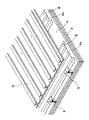
【図2】外囲体の一部を切欠した外観図である。
【図3】本発明の動作説明図である。
【図4】外囲体の断面説明図である。
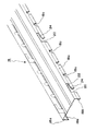
【図5】パネル取付金具の外観図である。
【図6】外囲体の他の実施の形態を示す断面図である。
【図7】同上、外観図である。
【図8】パネル取付金具の他の実施の形態を示す外観図である。
【図9】外囲体の他の実施の形態を示す断面図である。
【図10】同上、説明図である。
【図11】同上、説明図である。
【図12】外囲体の他の実施の形態を示す断面図である。
【符号の説明】
2 下地材
4 外囲板
4a 下位水平部
4b 立ち上り部
4c 引掛部
4d 立ち上り部
4e 上位水平部
6 パネル取付金具
6a 支持板部
6b 側板部
6c 下位水平部
6d 一端部
8 接合部
10 挿入凹部
12 はぜ部収納凹部
14 係合突片
16 パネル
18 取付金具
18a 側板部
18b 折り返し部
18c 排水穴
20 挿入凹部
22 はぜ部収納凹部
24 係合突片
26 下地材
28 タイトフレーム
30 外囲板
30a 立ち上り部
30b 立ち上り部
32 吊子
33 接合部
34 パネル取付金具
34a 側板部
36 挿入凹部
38 はぜ部収納凹部
40 係合突片
42 押え金具
44 押え金具[0001]
BACKGROUND OF THE INVENTION
TECHNICAL FIELD The present invention relates to an outer enclosure such as a roof or an outer wall to which a panel such as a decorative plate or a solar battery panel is attached, and a panel mounting bracket for attaching the panel on the outer enclosure constituting the outer enclosure.
[0002]
[Prior art]
2. Description of the Related Art Conventionally, a roof or an outer wall in which a panel member such as a decorative board or a solar panel (solar cell panel) is attached to an outer enclosure is known. These panels are fixed to the surrounding plate by a fastening device such as a screw directly, or have a special structure for mounting on the panel member side and the surrounding plate side.
[0003]
[Problems to be solved by the invention]
When the panel is directly screwed to the outer casing, rainwater leaks from the screw-fastening portion, so that packing and other waterproofing treatments are required, and this processing is troublesome and expensive, resulting in high costs.
In addition, it is necessary to design a special structure for mounting on the panel side and the envelope side, which increases the cost. In addition, there is a case where a work such as welding is accompanied with the attachment, and there is a problem that a panel such as a decorative board cannot be easily attached to the outer cover.
The present invention aims to solve the above problems.
[0004]
[Means for Solving the Problems]
In order to achieve the above object, according to the present invention, a plurality of envelope plates (4) having rising portions (4b) and (4d) on both sides are arranged in parallel on a base material (2), and the envelope plates adjacent to each other. The upper part of the rising parts (4b) and (4d) of (4) is refracted to form the joint part (8), while the long strip-shaped support plate part (6a) is formed at right angles to both sides thereof. An insertion recess (10) having a width slightly larger than the width of the joining portion (8) in the side plate (6b) and a direction perpendicular to the insertion recess (10). The long panel mounting bracket (6) formed with the formed helical part accommodating recess (12) and the engaging protrusion (14) located at the bottom of the helical accommodating concave part (12) is joined to the above. Inserting the panel mounting bracket (6) on the joint (8) so as to be perpendicular to the longitudinal direction of the part (8) After the joint (8) is inserted into the recess (10), the panel mounting bracket (6) is displaced in the longitudinal direction, and the joint (8) is relatively moved into the helix storage recess (12). The engagement protrusion (14) is engaged with the lower surface of the joint (8), and the panel mounting bracket (6) is engaged with the envelope plate (4) so as not to move along its longitudinal direction. A panel (16) such as a decorative plate is attached to the panel mounting bracket (6).
[0005]
DETAILED DESCRIPTION OF THE INVENTION
Embodiments of the present invention will be described below in detail with reference to the accompanying drawings.
In FIG. 1, (2) is a base material for building a roof or outer wall made of plywood or the like, and a plurality of surrounding plates (4) made of a metal plate such as a long steel plate extending in the direction perpendicular to the paper surface are arranged in parallel. It arrange | positions and the rising part of the side part of each surrounding board (4) is joined by the screwing structure.
[0006]
On one side of each outer plate (4), there is a lower horizontal part (4a), a rising part (4b) having a double structure, and a double structure formed at a right angle to the upper part thereof. A hooking portion (4c) is formed. The lower horizontal portion (4a) is fixed to the base material (2) with a screw or the like from above a waterproof sheet (not shown) laid on the base material (2).
[0007]
A rising portion (4d) and an upper horizontal portion (4e) are formed at right angles to the upper end of the rising portion (4d) on the other side of each envelope plate (4), and the rising portion (4e) is adjacent to the rising portion (4e). It joins the rising part (4b) of the other envelope plate (4), and the upper horizontal part (4e) is screwed or bent to the hooking portion (4c) of the adjacent envelope plate (4). Has been.
[0008]
(6) is a panel mounting bracket made of a metal plate such as a long steel plate, and as shown in FIG. 5, a belt-like support plate portion (6a) and side plate portions formed perpendicular to both side ends thereof (6b) (6b) and lower horizontal portions (6c) (6c) formed by refraction at the lower ends of the side plate portions (6b) (6b).
[0009]
The side plate portions (6b) (6b) and the lower horizontal portions (6c) (6c) have the same interval as the interval between the junction portions (8) of the envelope plate (4), and the junction portions An insertion recess (10) having a width allowing loose fitting in (8) is formed to open downward. In the upper part of the side plate parts (6b) and (6b), there is formed a helical part accommodating concave part (12) extending in the longitudinal direction of the mounting bracket (6), and the concave part (12) is an upper part of the insertion concave part (10). Communicating with The portion of the side plate portion (6b) (6b) that forms the bottom portion of the helix storage recess (12) constitutes an engagement protrusion (14) for engaging with the lower surface of the joint (8). ing.
[0010]
(16) is a panel made of a decorative panel made of a metal material such as an aluminum mold. The panel (16) can be a solar panel or the like.
Next, with reference to FIG. 3, the operation | work which constructs a panel mounting bracket (6) on the junction part (8) of an outer peripheral board (4) is demonstrated.
[0011]
As shown in FIG. 3 (A), first, mounting brackets (6) are arranged on the surrounding plates (4) in a direction perpendicular to the longitudinal direction of each surrounding plate (4). As shown in FIG. 3 (B), the mounting bracket (6) is lowered, and the insertion recess (10) of the mounting bracket (6) is inserted into the joint (8).
[0012]
Next, as shown in FIG. 3 (C), the mounting bracket (6) is shifted to the left, and the joint portion (8) is stored in the helix storage recess (12) of the mounting bracket (6). The engagement protrusions (14) are engaged with the lower surfaces of the corresponding joint portions (8), and the tips of the engagement protrusions (14) are engaged with the side surfaces of the corresponding rising portions (4b).
[0013]
Next, as shown in FIG. 4, one end portion (6d) in the longitudinal direction of the mounting bracket (6) is bent downward and perpendicularly and engaged with the side surface of the corresponding rising portion (4d). Thereby, the movement of the mounting bracket (6) in the left-right direction is prevented and the upward movement is blocked by the engagement between the engaging protrusion (14) and the lower surface of the joint (8), and the mounting bracket (6). Is firmly mounted on the joint (8) by means of the outer plate (4).
[0014]
In the above-described manner, a plurality of mounting brackets (6) are provided at predetermined intervals as shown in FIG. 2 without using screws on the joint (8) of the outer envelope plate (4). After the attachment, a panel (16) such as a decorative plate is arranged on the support plate portion (6a) of the attachment fitting (6), and the panel (16) is fixed to the support plate portion (6a) with screws.
[0015]
In the embodiment described above, the cross-sectional shapes of the support plate portion (6a) and the side plate portion (6b) of the mounting bracket (6) are laterally U-shaped as shown in FIG. 5, and the side plate portions (6b) (6b). When the lower horizontal portions (6c) and (6c) are integrally formed at the lower end of the lower horizontal portion, the lower horizontal portions (6c) and (6c) are attached in a state where the mounting bracket (6) is attached to the envelope plate (4). ) And the upper surface of the envelope plate (4).
[0016]
However, the shape of the mounting bracket (6) is not particularly limited to the cross-sectional shape shown in FIG. As shown in FIG. 8, the mounting bracket has a substantially U-shaped cross-section, and has folded portions (18 b) (18 b) and drain holes ( 18c), and when the mounting bracket (18) is attached to the joint (8) of the envelope plate (4) as shown in FIGS. 6 and 7, the lower ends of the side plate portions (18a) (18a) It is good also as a structure closely_contact | adhered to the upper surface of a surrounding board (4).
[0017]
6, 7, and 8, (20) is an insertion recess formed in the side plate portions (18 a) and (18 a), (22) is a hull storage recess, and (24) is an engaging protrusion. The structure for attaching the mounting bracket (18) to the joint portion (8) of the envelope plate (4) is substantially the same as that of the first embodiment described above.
Next, a third embodiment of the present invention will be described with reference to FIGS.
[0018]
In FIG. 9, (26) is a beam made of I-shaped steel or H-shaped steel, and constitutes the base material of the roof of the building. A plurality of base materials (26) are arranged in parallel, and a tight frame (28) is fixed to the upper surface of these base materials (26). On the base material (26), a plurality of surrounding plates (30) made of a metal folded plate such as a plurality of steel plates are arranged in a state where the lower surfaces are fitted to the tight frame (28). .
[0019]
Rising portions (30a) and (30b) are formed on both sides of each envelope plate (30), and the rising portions (30a) and (30b) are formed on the convex portions of the corresponding tight frame (28). The hanger (32) fixed to the convex part and the rising part (30a) (30b) of the adjacent envelope (30) are joined and bent in the joined state. This bent part constitutes a joint part (33) by means of screwing. Each of the envelope plates (30) constitutes an envelope plate having a corrugated cross-sectional shape as a whole.
[0020]
(34) is a panel mounting bracket made of a metal plate such as a long steel plate having a U-shaped cross section, and the insertion recesses (36) are formed on both side plate portions (34a) on both sides of the support plate portion. A shell housing recess (38) and an engaging protrusion (40) are formed.
Next, with reference to FIG. 10, 11, the operation | work which constructs a panel mounting bracket (34) on the junction part (33) of an outer peripheral board (30) is demonstrated.
[0021]
First, the mounting bracket (34) is disposed on the outer casing (30) in a direction perpendicular to the longitudinal direction of each outer casing (30), and the mounting bracket (34) is lowered in this state. The insertion recess (36) of the mounting bracket (14) is inserted into the joint (33). Next, as shown in FIG. 10 (B), the mounting bracket (34) is shifted to the right, and the joint portion (33) is stored in the flange storage recess (38) of the mounting bracket (34). Each engaging protrusion (40) is engaged with the lower surface of each corresponding joint (33), and the leading end (30a) of the surrounding plate (30) corresponding to the tip of each engaging protrusion (40). Engage with the side).
[0022]
Next, as shown in FIG. 11, one end portion (34b) in the longitudinal direction of the mounting bracket (34) is bent downward in a right-angle direction, and is engaged with the side surface of the corresponding rising portion (30b) of the surrounding plate (30). Combine. As a result, the mounting bracket (34) is prevented from shifting in the left-right direction, and the upward movement is blocked by the engagement between the projecting piece (40) and the lower surface of the joint (33). Is firmly attached on the joint (33) of the envelope (30).
[0023]
In the above-described manner, the plurality of mounting brackets (34) are mounted on the outer cover plate (30) at predetermined intervals without using screws, and then a panel (16) such as a decorative plate is mounted. Is arranged on the support plate portion of the mounting bracket (34), and the panel (16) is fixed to the support plate portion of the mounting bracket (34) with screws. In addition, as shown in FIG. 12, the structure which fixes panels (16), such as a decoration board, to a mounting bracket, as shown in FIG. 12, supports metal plates (42) and (44), and a support plate of a mounting bracket (46). The panel (16) such as a decorative plate or a solar panel may be pressed by the presser fittings (42) and (44), and the panel (16) may be fixed to the mounting bracket (46). .
[0024]
The structure of the mounting bracket (46) is the same as that of the mounting brackets (6) and (18) of the first and second embodiments or the mounting bracket (34) of the third embodiment. As described above, the fitting portion receiving recesses (12), (22), and (38) of the mounting brackets (6), (18), and (34) are fitted and engaged with the joint portions (8) and (33) of the envelope plate. Since the projecting pieces (14), (24), and (40) are engaged with the joint portions (8) and (33), the mounting brackets (6), (18), and (34) have high strength against a downward vertical load. .
[0025]
【The invention's effect】
Since the present invention is configured as described above, the panel can be attached to the envelope plate with a simple structure.
[Brief description of the drawings]
FIG. 1 is a cross-sectional view of an enclosure.
FIG. 2 is an external view in which a part of an outer enclosure is cut away.
FIG. 3 is an operation explanatory diagram of the present invention.
FIG. 4 is a cross-sectional explanatory view of an envelope.
FIG. 5 is an external view of a panel mounting bracket.
FIG. 6 is a cross-sectional view showing another embodiment of an envelope.
FIG. 7 is an external view of the above.
FIG. 8 is an external view showing another embodiment of the panel mounting bracket.
FIG. 9 is a cross-sectional view showing another embodiment of an envelope.
FIG. 10 is an explanatory view of the same as above.
FIG. 11 is an explanatory diagram of the above.
FIG. 12 is a cross-sectional view showing another embodiment of an envelope.
[Explanation of symbols]
2
Claims (2)
Priority Applications (1)
| Application Number | Priority Date | Filing Date | Title |
|---|---|---|---|
| JP26515398A JP4076103B2 (en) | 1998-09-18 | 1998-09-18 | Enclosure and panel mounting bracket |
Applications Claiming Priority (1)
| Application Number | Priority Date | Filing Date | Title |
|---|---|---|---|
| JP26515398A JP4076103B2 (en) | 1998-09-18 | 1998-09-18 | Enclosure and panel mounting bracket |
Publications (2)
| Publication Number | Publication Date |
|---|---|
| JP2000096777A JP2000096777A (en) | 2000-04-04 |
| JP4076103B2 true JP4076103B2 (en) | 2008-04-16 |
Family
ID=17413374
Family Applications (1)
| Application Number | Title | Priority Date | Filing Date |
|---|---|---|---|
| JP26515398A Expired - Fee Related JP4076103B2 (en) | 1998-09-18 | 1998-09-18 | Enclosure and panel mounting bracket |
Country Status (1)
| Country | Link |
|---|---|
| JP (1) | JP4076103B2 (en) |
Families Citing this family (4)
| Publication number | Priority date | Publication date | Assignee | Title |
|---|---|---|---|---|
| JP4155948B2 (en) * | 2004-06-30 | 2008-09-24 | 元旦ビューティ工業株式会社 | Renovation structure of building |
| JP4607983B2 (en) * | 2008-03-28 | 2011-01-05 | 元旦ビューティ工業株式会社 | Renovation structure of building |
| JP5313649B2 (en) * | 2008-12-12 | 2013-10-09 | 三晃金属工業株式会社 | Folded plate roof power frame body and folded plate roof power frame structure |
| KR101001214B1 (en) | 2010-07-07 | 2010-12-15 | 주식회사 스틸콘 | Roof Panel Fixture in Prefab Building |
-
1998
- 1998-09-18 JP JP26515398A patent/JP4076103B2/en not_active Expired - Fee Related
Also Published As
| Publication number | Publication date |
|---|---|
| JP2000096777A (en) | 2000-04-04 |
Similar Documents
| Publication | Publication Date | Title |
|---|---|---|
| CN102667028B (en) | Auxiliary members | |
| JP3299877B2 (en) | Mounting hardware used for mounting solar cell module, mounting structure of solar cell module, and roof mounted with solar cell module | |
| JP4062567B2 (en) | Device for mounting panel-like structures on the outer surface | |
| JP2004300865A (en) | Architectural plate with solar cells | |
| JP4076103B2 (en) | Enclosure and panel mounting bracket | |
| JP2009174250A (en) | Folded-plate roof, folded-plate roof cover, and tight frame | |
| JP2009249810A (en) | Rooftop structure mounting fitting for folded plate roof | |
| JP4062566B2 (en) | Envelope | |
| KR101111456B1 (en) | Clamp for a solar cell plate | |
| CN214302583U (en) | Plate body connecting component | |
| JP4342658B2 (en) | Solar cell module panel mounting device, gantry mounting device, and enclosure | |
| JP4229516B2 (en) | Enclosure and enclosure plate for solar cell module panel | |
| JP4007017B2 (en) | Temperature control system using a double roof | |
| JP4212195B2 (en) | Solar cell module panel mounting device for roof | |
| JP7137681B1 (en) | Roof supports and double-layer folded-plate roofs | |
| JP7369043B2 (en) | Solar cell mounting structure | |
| JP7358250B2 (en) | Solar cell mounting structure | |
| JPH06506Y2 (en) | Building board joint member | |
| JP2011174332A (en) | Implement for being mounted on roof, and structure for mounting the same | |
| JPS6117134Y2 (en) | ||
| JP3854376B2 (en) | Flat envelope and envelope | |
| JPS5869953A (en) | Roof member | |
| JP2025116328A (en) | Seam-type folded plate roof joint structure | |
| JPH0728280Y2 (en) | Roof structure with cap member | |
| JPS61183548A (en) | Joint structure in inlaid outer enclosure |
Legal Events
| Date | Code | Title | Description |
|---|---|---|---|
| A621 | Written request for application examination |
Free format text: JAPANESE INTERMEDIATE CODE: A621 Effective date: 20050909 |
|
| A977 | Report on retrieval |
Free format text: JAPANESE INTERMEDIATE CODE: A971007 Effective date: 20071225 |
|
| TRDD | Decision of grant or rejection written | ||
| A01 | Written decision to grant a patent or to grant a registration (utility model) |
Free format text: JAPANESE INTERMEDIATE CODE: A01 Effective date: 20071228 |
|
| A61 | First payment of annual fees (during grant procedure) |
Free format text: JAPANESE INTERMEDIATE CODE: A61 Effective date: 20080125 |
|
| R150 | Certificate of patent or registration of utility model |
Free format text: JAPANESE INTERMEDIATE CODE: R150 |
|
| FPAY | Renewal fee payment (event date is renewal date of database) |
Free format text: PAYMENT UNTIL: 20110208 Year of fee payment: 3 |
|
| LAPS | Cancellation because of no payment of annual fees |