JP4136479B2 - Liquid ejection apparatus and liquid ejection method - Google Patents
Liquid ejection apparatus and liquid ejection method Download PDFInfo
- Publication number
- JP4136479B2 JP4136479B2 JP2002177284A JP2002177284A JP4136479B2 JP 4136479 B2 JP4136479 B2 JP 4136479B2 JP 2002177284 A JP2002177284 A JP 2002177284A JP 2002177284 A JP2002177284 A JP 2002177284A JP 4136479 B2 JP4136479 B2 JP 4136479B2
- Authority
- JP
- Japan
- Prior art keywords
- nozzle
- head
- defective
- ejection
- nozzles
- Prior art date
- Legal status (The legal status is an assumption and is not a legal conclusion. Google has not performed a legal analysis and makes no representation as to the accuracy of the status listed.)
- Expired - Fee Related
Links
Images



Landscapes
- Ink Jet (AREA)
Description
【0001】
【発明の属する技術分野】
本発明は、インクジェット法を利用した液体吐出装置の溶液吐出部の不良ノズル情報を記録管理し、不良ノズルを使って印字することがなく、また不良ノズルを保持するマルチノズルヘッド(以降「ヘッド」と略す場合がある)を使用しても正常に印字可能な装置および媒体に関するものである。
【0002】
【従来の技術】
インクジェット装置において印字ヘッドは、不吐出(印字不良)があれば、回復(クリーニング)処理を数回繰り返し溶液の固着、汚染部を排除して再度印字して印字不良が見られれば当該ヘッドの不良として新規のものと交換するか、不吐出(印字不良)の原因となるノズルのかわりに代替ノズルを使って正常に印字できるようにするシステムが一般的な方法であった。そのため、印字操作ごとに印字をする前にヘッドの検査のために予備印字テストを実施しなければならず、不吐出の状況によっては、不良ノズルを使わず代替ノズルを使うように印字データを作りなおすことも必要になるため印字効率が悪いと指摘があった。
【0003】
【発明が解決しようとする課題】
本発明の目的は、印字操作ごとに予備吐出検査を行う繁雑さを解消し、更に、吐出不良のノズルがある場合には、それを使用しなくても所望とする画像の媒体上での形成が可能である液体吐出装置および液体吐出方法を提供することにある。
【0004】
【課題を解決するための手段】
本発明にかかる液体吐出装置は、基板上の異なる位置に、異なるプローブを含む液滴をそれぞれ吐出して配置されたプローブアレイを製造するための液体吐出装置であって、
前記液体吐出装置は、異なるプローブを含む液滴を吐出可能なノズルの複数がマトリックスに配置された吐出面を有するマルチノズルヘッドと、
基板上に液滴を吐出する前に該当する不良ノズルの場所を特定するために、マルチノズルヘッドの不良ノズルのマトリックス位置に関する情報を記憶するメモリから該情報を読みこむ読み取り手段と、
前記読み取り手段によって読み取られた不良ノズルのマトリックス位置に基づいて前記不良ノズルからの吐出を除いた描画画像を形成する手段と、
前記読み取り手段によって読み取られた不良ノズルのマトリックス位置に基づいて前記描画画像における未吐出の位置に、該不良ノズルの代替となる代替ノズルを指定して、該ノズルより不良ノズルの供給位置に液滴を供給する2回目の描画を制御する手段と、
を有することを特徴とする。
【0005】
本発明にかかる液体吐出方法は、基板上の異なる位置に、異なるプローブを含む液滴をそれぞれ吐出して配置されたプローブアレイを製造するための液体吐出方法であって、
異なるプローブを含む液滴を吐出可能な複数のノズルがマトリックスに配置された吐出面を有するマルチノズルヘッドと、基板上に液滴を吐出する前に該当する不良ノズルの場所を特定するために、マルチノズルヘッドの不良ノズルのマトリックス位置に関する情報を記憶するメモリから該情報を読みこむ読み取り手段と、を用い、
前記読み取り手段によって読み取られた不良ノズルのマトリックス位置に基づいて前記不良ノズルからの吐出を除いた描画画像を形成する工程と、
前記読み取り手段によって読み取られた不良ノズルのマトリックス位置に基づいて前記描画画像における未吐出の位置に、該不良ノズルの代替となる代替ノズルを指定して、該ノズルより不良ノズルの供給位置に液滴を供給する2回目の描画を行う工程と、
を有することを特徴とする。
【0006】
メモリを有する不揮発性の記憶手段は、ヘッド、液体吐出装置の製造装置本体またはコントロール装置に組み込まれており、常時更新可能でかつヘッド単位で管理し情報を変更することができるようにすることが好ましい。また、不揮発性の記憶手段のメモリには、ノズルの位置、ノズルの利用の可否、代替ノズルの有無を更に記録可能であり、不揮発性メモリに記録する情報はヘッドの出荷検査時のテスト印字過程で個々のノズルの吐出性能試験を実行して得られるものとすることができる。
【0007】
本発明は、従来の方法のようにヘッドの性能を検査するために毎回印字する前にテスト印字することを止めて、不良ノズルを特定したらその情報を次回以降の印字に活用するものである。使うヘッドによっては、出荷時にすでに不良ノズルを保持するものもあり、不良ノズルの代わりのノズル(以後代替ノズルという)を使えば使用に耐えられるが、一方で、毎回予備テスト印字を実行しそのたびに印字データを作り変える手間とコストが生じ、かかる工程は無視できない課題になっていた。本発明はかかる課題を解決するものである。
【0008】
本発明の一態様は、インクジェット方式の液体吐出装置において印字不良を生じるヘッドのノズル情報をヘッド内、液体吐出装置本体内またはPCで構成し得るコントロール装置内にある不揮発性のメモリ、たとえばEEPROMに保存し、ヘッドの出荷時にノズルの検査工程で調べられた個々のノズルの性能評価情報を蓄積することを特徴とするものである。
【0009】
また、本発明の他の態様は、液体吐出装置に装着するヘッドは単体ごとにその性能を評価される手段をもち、必ずヘッドの出荷前に検査される工程をもつ。本発明の液体吐出装置には、例えば、マルチノズルヘッドの場合、個々のノズルに対して印字の良否を判定しその全情報を前記EEPROMに記憶する手段をもち、通常印刷時には、液体吐出装置にデータを送り制御コードを生成するPCはこのEEPROMのノズル性能評価情報を確認する手段をもち、印字前に、ノズル不良情報から生成されるマスク画像と印字する画像とのAND情報から不良ノズルを使わない第一の画像生成手段と、不良ノズルを使わないようにマスクされた画像をビットシフトする第二の画像生成手段と、シフトされた分のピッチに相当する印字開始位置などを印字制御コードに修正を加える制御コード修正手段とから、第一の画像と第二の画像とを重ね合わせて印字することを特徴とする液体吐出装置が含まれる。
【0010】
不揮発性メモリ(EEPROM)は、へッドまたは液体吐出装置本体またはパーソナルコンピューター(PC)にあるものとし、かつ、ヘッド固有の情報を記録するために情報が常に搭載したヘッドのものになるように識別手段を有することも特徴とする。通常、ヘッドにEEPROMを搭載し、PC・液体吐出装置側と通信することでヘッド固有の情報を常時取り入れる手段をもつことが自然であるが、ヘッドに識別子をつけてヘッドと異なる場所にEEPROMを設けて対応関係を結合できればその手法は問わない。
【0011】
以下、本発明に用いるのに好適なインクジェット方式による液体吐出装置などについて説明する。
【0012】
(インクジェット液体吐出装置)
図1は、本発明の実施例を実現するための液体吐出装置の概観図である。
【0013】
液体吐出装置本体100には、供給システムとして吐出する溶液のリザーバ102と溶液を吐出するヘッド101、吐出された液滴を定着させる図示しない媒体を固定するステージ106によって構成され、電源スイッチ107により初期化されたシステムは、吐出ヘッド101をガードレール104に沿って左右に駆動し、ステージ106をガードレール105に沿って前後に駆動することを可能にし、描画対象のパターンと駆動系情報、例えば、ヘッド・ステージの駆動ピッチ、速度、吐出開始位置の情報は、コントロール装置であるPCに接続されたケーブル103によって、送受信される。溶液の供給システムは直接、図示しないシリンジ等を使ってリザーバ102に注入しても、図示しない着脱式のタンクを吐出ヘッドに装着して吸引してもよく本発明の本質に係るところではない。
【0014】
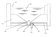
図2は、液滴を吐出するノズル(噴射部)の断面図である。
【0015】
ヘッドの液体吐出面の噴射口(ノズル)のひとつを拡大してみた断面構造図である。ガラス基板200およびシリコン基板201等に囲まれて、溶液を供給するリザーバ202と、溶液をノズルに供給する供給口203、溶液をノズルまで誘導する流路204と、吐出部位であるノズルには、溶液を加熱するヒータ207と過熱によって生成された泡205によって飛翔する液滴206を図示している。ヒータは、蓄熱層209と保護膜208によって覆われ保護されている。
【0016】
これは、特にインクジェット記録方式の中でも、インク吐出を行わせるために利用されるエネルギーとして熱エネルギーを発生する手段(例えば電気熱変換体やレーザ光等)を備え、前記熱エネルギーによりインクの状態変化を生起させる方式を用いることにより記録の高密度化、高精細化が達成できる。
【0017】
その代表的な構成や原理については、例えば、米国特許第4723129号明細書、同第4740796号明細書に開示されている基本的な原理を用いて行うものが好ましい。この方式はいわゆるオンデマンド型、コンティニュアス型のいずれにも適用可能であるが、特に、オンデマンド型の場合には、溶液が保持されているシートや液路に対応して配置されている電気熱変換体に、記録情報に対応していて核沸騰を越える急速な温度上昇を与える少なくとも1つの駆動信号を印加することによって、電気熱変換体に熱エネルギーを発生せしめ、ヘッドの熱作用面に膜沸騰を生じさせて、結果的にこの駆動信号に1対1で対応した溶液内の気泡を形成できるので有効である。
【0018】
この気泡の成長、収縮により吐出用開口を介して溶液を吐出させて、少なくとも1つの液滴を形成する。この駆動信号をパルス形状とすると、即時適切に気泡の成長収縮が行われるので、特に応答性に優れた液滴の吐出が達成でき、より好ましい。
【0019】
このパルス形状の駆動信号としては、米国特許第4463359号明細書、同第4345262号明細書に記載されているようなものが適している。なお、上記熱作用面の温度上昇率に関する発明の米国特許第4313124号明細書に記載されている条件を採用すると、さらに優れた記録を行うことができる。
【0020】
上記実施形態では、シリアル型のインクジェットプリンタ特に、電気熱変換体(ヒータ)を例に挙げて説明したが、本発明は記録ヘッドが交換可能な記録装置であれば、これ以外の方式に従って記録を行う記録装置にも広く適用できる。
【0021】
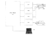
図3は、本発明で機能するブロック図である。液体吐出装置は、PC315、PCIBOX300と図示しないインタフェースおよび図示しないコントロール用ソフトウェアを含むPCエリアと、カートリッジ用モータドライバ301、ステージ用モータドライバ304、ヘッド中継PCB302と電源系統を含む中継エリアと、液体吐出装置本体であるカートリッジ310、ステージの搭載された定盤314で構成される装置本体エリアからなる。カートリッジ310は、ヘッド308、ヘッド別アダプタPCB307、カートリッジを駆動するリニアモータ306、エンコーダ305、それに、本発明の主要部である不揮発性メモリ(EEPROM)309から構成され、また、定盤314にはステージ311が搭載され、ステージを駆動するリニアモータ312、エンコーダ313がある。
【0022】
(吐出ヘッドの印字不良情報を記録する不揮発性メモリ)
吐出ヘッドの内部回路に不揮発性メモリ(ここでは以後EEPROMとする)を搭載し、メモリには、ヘッドの吐出性能に関するパラメータを保存し最適なパフォーマンスを実施できるようにヘッドの出荷時に記録している。ここでは、吐出不良箇所を該当するノズル場所を指定する情報をこのEEPROMの空き領域に保存し、以降、不具合のあるノズルを使用しないように制御プログラムに該情報を提供できるようにする。一例として1024ノズルヘッドの場合、EEPROMに128バイトの空き領域があれば、吐出正常ビット1、吐出不良0を記録できる。
【0023】
図4は、EEPROMのメモリ図である。全サイズ2kバイトのメモリであり、表の左端には16進数で0x10バイトおきの番地を、表の上端には番地の一桁目を記している。ヘッドの特性データに係るパラメータを0番地〜0x77F番地に、前記吐出不良箇所のノズル情報、ノズル評価データに係るパラメータを0x780〜0x800番地に記録する。正常/異常ノズルをビットの1/0で記録する。図4では、全てのノズルが正常であることを0xFFで記録されている。
【0024】
【実施例】
本実施例では、プローブを石英ガラス基板に吐出し固定するマイクロアレイ製造装置に関しては、特開平11−187900号公報記載のプローブの固相へのスポッティング方法に従う。ヘッドは、吐出噴射口(ノズル)単位で液種の異なる1024ノズル1024液種吐出のマルチノズルヘッドとする。図5は32行x32列のマトリックスノズルヘッドの噴射口(ノズル)501側の平面図であり、各ノズルへの溶液の供給部は溶液の貯蔵槽(リザーバ)または、着脱式のタンクで、図示しない反対の面に設定されている。噴射口(ノズル)501側の吐出面500には、微細な1024本の噴射口(ノズル)501がマトリックスに配列されている。図5のようにX-Yの2次元軸を考え、各噴射口(ノズル)の座標を(X,Y)として記述する。
【0025】
ヘッドの電子回路部には、ヘッドの特性データを記録するEEPROMを搭載し、前述した図4のようにデータを区分けし、吐出噴射口(ノズル)の吐出不良の有無を記録するエリアを設けている。ここは、図5の吐出噴射口(ノズル)のマトリックスを(0,0)(1,0)(2,0)・・・(0,1)(1,1)・・(29,31)(30,31)(31,31)の順に図4のEEPROMエリアの0x780〜0x800番地に記録する。ただし記録の順番、構成は特定のものに限定するものではなく、1対1の対応関係があればその手法は問わない。
【0026】
ヘッドの特性データは、通常ヘッドの出荷検査時に性能試験の過程で調査され前記EEPROMに記録するが、液滴噴射部の不良情報はこのときに1024本のノズル検査を実施し、液滴を噴出しない部位のビットを0としてマスクし所定のEEPROMの番地に記録する。
【0027】
マイクロアレイ製造装置で液体吐出に使うヘッドとして要求される性能は、高密度に高品位(高精度)にプローブのスポットを吐出させ基板に固定させることであり、1スポットあたり1種のプローブを固定させる上で該当するノズルが吐出不良であることはそれが1スポットであってもマイクロアレイ媒体の欠陥品を作製することになる。すなわち、マイクロアレイを構成するプローブのスポット数、スポット配置、スポット解像度によっては、対応ノズルの不吐検査を実施した後に変更を余儀なくされるかヘッド自体を新規に交換する必要があった。これは、マイクロアレイ製造工程において効率面で、ノズル不良に対処する検査工程のやり直し、描画データの変更、ヘッドの交換等の時間ロスを生じ、また、コスト面でも吐出用溶液の使用量、高品質ヘッドの生産量、人件費等の増大の主要因となった。
【0028】
本発明は、ごく少数のノズル不良がある吐出ヘッドであっても所望のプローブを所望の位置に所望の解像度で高品位にスポットしたマイクロアレイ媒体の製造を目的とし、予めヘッドの特性試験で取得した全ての噴射口(ノズル)の吐出性能において、液滴の吐出可能なものと吐出不能なものとを選り分けし吐出ヘッドの電子回路部にあるEEPROMにデータを保存する。図6は、吐出ヘッドの集荷検査時における吐出性能試験のフローチャートである。6−1は、新規の吐出ヘッドを装着し液体吐出装置を初期化するプロセスであり、ヘッド固有の特性パラメータをロードし、そのヘッドでの描画を最適化する前処理もこれに含む。6−2は、描画データ生成・転送装置(通常PC)から吐出性能を検査するパターンを転送し1024ノズル(32行x32列マトリックス)全てについて吐出テストを行う。このとき使用する溶液は本印字用と同等のものが望ましいが高価な場合、粘性・表面張力・PHをはじめとする物性値の同じ安価な代替溶液にしてもよい。図5のように構成された1024ノズルの32x32マトリックスヘッドをX-Y方向に100μmピッチでずらし印字することで1ノズルあたり複数回数吐出を繰り返し、複数イベントでの差異を見ることができる。液滴の吐出先の媒体、その結果をスキャンする装置・方法は、本発明を制限するものではない。6−3は、ヘッドのEEPROMに吐出ノズルの評価結果を書き込むプロセスである。
【0029】
図7は、前述の吐出性能試験の描画結果を示した描画媒体の簡略図である。上図は、媒体700に前記1024ノズルのヘッドで一回だけ全ノズルの吐出した結果で、スポット数は1024、ピッチは噴射口(ノズル)のピッチの1.6mmになる。これを、100μmごとにX-Y方向にスライドし16回描画を繰り返すことで、下図のように拡大すると、同一噴射口(ノズル)で16x16の100μmピッチのスポット観察することができる。これらの256スポット全てが正常に吐出できている場合に吐出正常なノズルとして前記のEEPROMの対応する番地のビットに1を、不良スポットが含まれていたら該当する番地のビットを0にする。
【0030】
図8はヘッドの吐出ノズル評価結果を書き込むEEPROM領域と対応する噴射口(ノズル)との対応関係を明示した簡略図である。吐出不良ノズルと判定できる該当ビットを0とする。ここでは、(1,27)、(1,28)、(1,30)、(2,28)、(5,1)、(6,3)、(7,3)、(29,28)、(30,0)、(30,1)、(30,28)、(31,1)に配置する噴射口(ノズル)を不良ノズルと判定し、下表のようにEEPROMの対応番地に0値が書き込まれている。
【0031】
図9は、マイクロアレイ製造装置において液滴を吐出する描画工程を示したフローチャートである。9−1では、製造するマイクロアレイ製造用ガラス基板を描画装置のステージに設置し吐出する溶液を供給槽に注入するプロセスである。9−2は、描画を指示する制御コードを生成するPCと前記のEEPROMとの通信プロトコルを実行するプロセスである。9−3は、このとき不良ノズルの有無によって各々のマスク画像生成プログラムを呼び出す分岐プロセスである。9−4は、PCで取得したヘッドの吐出性能データを使ってマスク画像を作成するプロセスである。9−5は、吐出不良ノズルがなかった場合に全ビット1のマスク画像(マスクしない画像)を作成するプロセスである。9−6は、9−4、9−5で作られたマスク画像と描画する本画像とをAND処理することによって、1回目にヘッドで正常に描画することができる最大の画像パターンを作るプロセスである。9−7は、マスク画像をX-Y方向に1ビットずつシフトするプロセスで、9−8は、元のマスク画像とORすることで不良ノズルと一致しないパターン作成し9−9でOR結果が全て1になるまで検索するプロセスを示す。9−10では、作成した最終シフト画像をビット反転することで、未吐出の画像だけを代替ノズルで2回目に吐出できるように加工するプロセスである。9−11は、9−6で作成した画像パターンを描画するプロセスを9−12では9−10で作成した画像パターンをシフトしたピッチ分だけ描画開始位置を変更するプロセスである。9−13は、9−10で作成した残りの画像パターンを9−12で変更した描画制御用コードを変更することで2回目の描画で一枚の画像に重ね合わせて描画するプロセスである。9−14は、描画を完了し液体吐出装置の後プロセスとPCへ描画が完了したことを伝達し、画像データの転送を終結するプロセスである。
【0032】
前述してきたように、液体吐出装置のヘッドの噴射口(ノズル)の吐出不良を予めのテストパターンで調査しEEPROMに記録しておくことで、描画するたびにノズル検査を実施する必要がなくなることで、溶液の消費量を減少させ媒体の製造工程を短縮することができる。特に、ノズル別に供給する溶液が異なる多ノズルヘッドの場合、全ノズルを不良なく生産することは現実的ではなくコストも増大するため、未使用のノズルを多く抱えるヘッドの場合、不良ノズルへ供給する予定であった溶液を他の余剰ノズルに供給し、元画像を個々のヘッドの不良ノズル情報でマスクし複数のフレームに分けて合成することはヘッドの生産性を向上することにもなる。
【0033】
【発明の効果】
液体吐出装置において、一部吐出不良を生じる噴射口(ノズル)を保持するマルチノズルヘッドにおいて、不良部を特定する位置情報を、予め不揮発性メモリ(EEPROM)に記録しておき、本吐出時には、このノズル不吐情報から正常に利用可能な噴射口(ノズル)を使った描画データと別途不良噴射口(ノズル)を代替した噴射口(ノズル)を使った描画データとに振り分けを行い、完成度の低いヘッドであっても液体吐出装置として問題なく使用に耐えられる効果がある。また、毎回ノズルの検査用のテストを行うこともなく溶液の使用量を減らし作製する媒体のコストダウンとヘッドの歩留まりを相対的に上げることができるのも効果として無視できない。
【図面の簡単な説明】
【図1】液体吐出装置の概観図である。
【図2】液体吐出ノズルの断面構造図である。
【図3】液体吐出装置のブロック図である。
【図4】不揮発性メモリ(EEPROM)のノズル不良データ記録である。
【図5】マルチノズルヘッドの吐出面のノズル列を図示した説明図である。
【図6】吐出ヘッドの集荷検査時における吐出性能試験のフローチャートである。
【図7】ノズル検査パターンの2次元方向の吐出結果イメージ図である。
【図8】吐出不良ノズルとその対応するEEPROM領域を示した簡略図である。
【図9】マイクロアレイ製造装置の媒体への描画工程を示したフローチャートである。
【符号の説明】
100 液体吐出装置本体
101 吐出ヘッド
102 溶液供給リザーバ(タンク)
103 コントロール装置(PC)との通信ケーブル
104 ヘッドの駆動方向ガイドレール
105 ステージ駆動方向ガイドレール
106 ステージ・描画媒体設置テーブル
107 電源スイッチ
200 ガラス基板
201 シリコン基板
202 リザーバ(液の供給タンク)
203 液の供給口
204 液の流路
205 泡(バブル)
206 液滴
207 ヒータ
208 保護膜
209 蓄熱層
300 PCI BOX (プリントコントロールPCB・ヘッドドライバPCB・シリアルインターフェース)
301 カートリッジ用モータドライバ
302 ヘッド中継PCB
303 電源
304 ステージ用モータドライバ
305 エンコーダ
306 カートリッジリニアモータ
307 ヘッド別アダプタPCB
308 ヘッド
309 EEPROM
310 カートリッジ
320 媒体吸着用ステージ
321 ステージリニアモータ
313 エンコーダ
314 定盤
315 PC
500 吐出面(オリフィス面)
501 32×32に配列された噴射口(ノズル)
700 吐出ノズルの評価用テストパターンの描画
701 吐出ノズルの評価用テストパターンの描画における一部拡大図[0001]
BACKGROUND OF THE INVENTION
The present invention records and manages defective nozzle information of a solution discharge portion of a liquid discharge apparatus using an ink jet method, does not print using a defective nozzle, and holds a defective nozzle (hereinafter referred to as “head”). It is related with the apparatus and medium which can be printed normally even if it is used.
[0002]
[Prior art]
In the ink jet apparatus, if there is non-ejection (printing failure), the recovery (cleaning) process is repeated several times to fix the solution, remove the contaminated part, print again, and if printing failure is found, the head is defective. As a general method, the system can be replaced with a new one, or a normal nozzle can be used for printing instead of a nozzle that causes non-ejection (printing failure). Therefore, a preliminary print test must be performed to check the head before printing for each print operation. Depending on the non-ejection situation, print data should be created so that a substitute nozzle is used instead of a defective nozzle. It was pointed out that the printing efficiency was poor because it was necessary to correct it.
[0003]
[Problems to be solved by the invention]
An object of the present invention is to eliminate the complexity of performing preliminary ejection inspection for each printing operation, and further, when there is a nozzle with defective ejection, formation of a desired image on a medium without using it. It is an object of the present invention to provide a liquid ejection apparatus and a liquid ejection method that can perform the above-described process.
[0004]
[Means for Solving the Problems]
A liquid ejection apparatus according to the present invention is a liquid ejection apparatus for manufacturing a probe array arranged by ejecting liquid droplets including different probes at different positions on a substrate,
The liquid ejection apparatus includes a multi-nozzle head having an ejection surface in which a plurality of nozzles capable of ejecting droplets including different probes are arranged in a matrix;
Reading means for reading the information from a memory for storing information on the matrix positions of the defective nozzles of the multi-nozzle head in order to identify the location of the corresponding defective nozzles before discharging droplets onto the substrate;
Means for forming a drawn image excluding discharge from the defective nozzle based on the matrix position of the defective nozzle read by the reading means;
Based on the matrix position of the defective nozzle read by the reading means, an alternative nozzle that substitutes for the defective nozzle is designated at an undischarged position in the drawing image, and the droplet is supplied from the nozzle to the supply position of the defective nozzle. Means for controlling the second drawing to supply
It is characterized by having.
[0005]
A liquid discharge method according to the present invention is a liquid discharge method for manufacturing a probe array in which droplets containing different probes are respectively discharged at different positions on a substrate,
In order to identify the location of a defective nozzle before discharging a droplet onto a substrate, a multi-nozzle head having a discharge surface in which a plurality of nozzles that can discharge droplets including different probes are arranged in a matrix, Reading means for reading the information from the memory for storing the information on the matrix position of the defective nozzle of the multi-nozzle head,
Forming a drawn image excluding discharge from the defective nozzle based on the matrix position of the defective nozzle read by the reading means;
Based on the matrix position of the defective nozzle read by the reading means, an alternative nozzle that substitutes for the defective nozzle is designated at an undischarged position in the drawing image, and the droplet is supplied from the nozzle to the supply position of the defective nozzle. A second drawing process for supplying
It is characterized by having.
[0006]
The nonvolatile storage means having a memory is incorporated in the head, the manufacturing apparatus main body of the liquid ejection device, or the control device, and can be updated at any time, and can be managed and changed in units of heads. preferable. In addition, the memory of the nonvolatile storage means can further record the position of the nozzle, the availability of the nozzle, and the presence or absence of an alternative nozzle, and the information recorded in the nonvolatile memory is a test printing process at the time of head inspection. And can be obtained by executing a discharge performance test of each nozzle.
[0007]
In the present invention, test printing is stopped before printing every time in order to inspect the performance of the head as in the conventional method, and when a defective nozzle is identified, the information is used for the next printing. Depending on the heads used, defective nozzles are already held at the time of shipment, and use is possible if a nozzle instead of the defective nozzle (hereinafter referred to as alternative nozzle) is used, but on the other hand, preliminary test printing is performed each time. In this case, labor and cost for regenerating print data are generated, and such a process is a problem that cannot be ignored. The present invention solves this problem.
[0008]
One aspect of the present invention is that the nozzle information of a head that causes a printing defect in an ink jet type liquid ejecting apparatus is stored in a non-volatile memory such as an EEPROM in the head, in the liquid ejecting apparatus main body, or in a control device that can be configured by a PC. It is characterized by storing the performance evaluation information of the individual nozzles stored and examined in the nozzle inspection process at the time of shipment of the head.
[0009]
In another aspect of the present invention, the head to be mounted on the liquid ejection apparatus has a means for evaluating the performance of each head, and has a step of always inspecting the head before shipment. For example, in the case of a multi-nozzle head, the liquid ejection apparatus of the present invention has means for determining whether or not printing is good for each nozzle and storing all the information in the EEPROM. The PC that sends the data and generates the control code has a means to confirm the EEPROM nozzle performance evaluation information, and before printing, uses the defective nozzle from the AND information of the mask image generated from the nozzle failure information and the image to be printed. The first image generation means, the second image generation means for bit-shifting the masked image so as not to use the defective nozzle, and the print start position corresponding to the shifted pitch as the print control code. A liquid ejecting apparatus is characterized in that the first image and the second image are superimposed and printed from the control code correcting means for correcting.
[0010]
Non-volatile memory (EEPROM) shall be in the head or liquid ejecting device main body or personal computer (PC), and in order to record head-specific information, the information will always be that of the mounted head It also has an identification means. Normally, it is natural to install an EEPROM in the head and have a means to always take in information specific to the head by communicating with the PC / liquid ejection device side, but by attaching an identifier to the head and placing the EEPROM in a different place from the head Any method can be used as long as it can be provided and the correspondence can be combined.
[0011]
Hereinafter, an ink jet type liquid ejection apparatus suitable for use in the present invention will be described.
[0012]
(Inkjet liquid ejection device)
FIG. 1 is a schematic view of a liquid ejection apparatus for realizing an embodiment of the present invention.
[0013]
The liquid ejection apparatus
[0014]
FIG. 2 is a cross-sectional view of a nozzle (ejection unit) that ejects droplets.
[0015]
FIG. 4 is a cross-sectional structure diagram in which one of ejection ports (nozzles) on a liquid ejection surface of a head is enlarged. Surrounded by a
[0016]
This includes a means (for example, an electrothermal converter or a laser beam) that generates thermal energy as energy used for ink ejection, particularly in an ink jet recording system, and changes in the state of ink due to the thermal energy. By using a method for generating the recording, it is possible to achieve higher recording density and higher definition.
[0017]
As its typical configuration and principle, for example, those performed using the basic principle disclosed in US Pat. Nos. 4,723,129 and 4740796 are preferable. This method can be applied to both a so-called on-demand type and a continuous type. In particular, in the case of the on-demand type, it is arranged corresponding to a sheet or a liquid path holding a solution. By applying at least one drive signal corresponding to the recorded information and giving a rapid temperature rise exceeding the nucleate boiling to the electrothermal transducer, heat energy is generated in the electrothermal transducer, and the heat acting surface of the head This is effective because film boiling can be caused to occur, and as a result, bubbles in the solution corresponding to the drive signal can be formed on a one-to-one basis.
[0018]
By the growth and contraction of the bubbles, the solution is ejected through the ejection opening to form at least one droplet. It is more preferable that the driving signal has a pulse shape, since the bubble growth and contraction are performed immediately and appropriately, and thus it is possible to achieve discharge of a droplet with particularly excellent responsiveness.
[0019]
As this pulse-shaped drive signal, those described in US Pat. Nos. 4,463,359 and 4,434,262 are suitable. Further excellent recording can be performed by employing the conditions described in US Pat. No. 4,313,124 of the invention relating to the temperature rise rate of the heat acting surface.
[0020]
In the above embodiment, a serial type ink jet printer, particularly an electrothermal transducer (heater) has been described as an example. However, the present invention can perform recording according to other methods as long as the recording head can be replaced. The present invention can be widely applied to recording apparatuses.
[0021]
FIG. 3 is a block diagram that functions in the present invention. The liquid ejection device consists of PC315, PCIBOX300, PC area including interface (not shown) and control software (not shown),
[0022]
(Non-volatile memory that records printing head failure information)
A non-volatile memory (hereinafter referred to as EEPROM) is installed in the internal circuit of the ejection head, and parameters related to the ejection performance of the head are stored in the memory and recorded at the time of shipment of the head so that optimum performance can be implemented. . Here, information for designating the nozzle location corresponding to the ejection failure location is stored in this empty area of the EEPROM so that the information can be provided to the control program so as not to use the defective nozzle. For example, in the case of a 1024 nozzle head, if there is a 128-byte free area in the EEPROM, the ejection
[0023]
FIG. 4 is a memory diagram of the EEPROM. This is a memory of 2k bytes in all sizes, with addresses in hexadecimal notation at 0x10 byte intervals at the left end of the table and the first digit of the address at the upper end of the table. The parameters relating to the head characteristic data are recorded at
[0024]
【Example】
In this embodiment, the microarray manufacturing apparatus that discharges and fixes a probe to a quartz glass substrate follows the spotting method of a probe to a solid phase described in JP-A-11-187900. The head is a multi-nozzle head capable of discharging 1024 nozzles and 1024 liquid types having different liquid types in units of discharge ejection ports (nozzles). FIG. 5 is a plan view on the side of an injection port (nozzle) 501 of a matrix nozzle head of 32 rows × 32 columns, and a solution supply unit to each nozzle is a solution storage tank (reservoir) or a detachable tank. Not set on the opposite side. On the
[0025]
The electronic circuit of the head is equipped with an EEPROM that records the characteristic data of the head, and the data is divided as shown in FIG. 4, and an area for recording the presence or absence of ejection failure at the ejection nozzles (nozzles) is provided. Yes. Here, the matrix of discharge injection nozzles (nozzles) in FIG. 5 is (0,0) (1,0) (2,0) ... (0,1) (1,1) ... (29,31) Record in the order of (30, 31) (31, 31) at addresses 0x780 to 0x800 in the EEPROM area in Fig. 4. However, the order and configuration of recording are not limited to specific ones, and any method can be used as long as there is a one-to-one correspondence.
[0026]
The head characteristic data is usually investigated during the performance test during head inspection and recorded in the EEPROM, but the defect information of the droplet ejecting section is inspected for 1024 nozzles at this time and ejects the droplet. The bits of the part not to be masked are set to 0 and recorded at a predetermined EEPROM address.
[0027]
The performance required as a head used for liquid ejection in a microarray manufacturing apparatus is to eject probe spots at high density and high quality (high accuracy) and fix them to the substrate. One type of probe is fixed per spot. The fact that the corresponding nozzle in the above is defective in ejection means that a defective microarray medium is produced even if it is one spot. In other words, depending on the number of spots of the probes constituting the microarray, the spot arrangement, and the spot resolution, it has been necessary to change the nozzle after the discharge failure inspection of the corresponding nozzle or to replace the head itself. This leads to efficiency loss in the microarray manufacturing process, causing time loss such as redoing the inspection process to deal with nozzle defects, changing drawing data, replacing the head, etc. Also, in terms of cost, the amount of ejection solution used, high quality This was the main factor in the increase in head production and labor costs.
[0028]
The present invention is intended to produce a microarray medium in which a desired probe is spotted at a desired position at a desired resolution and with a high quality even with an ejection head having a very small number of nozzle defects. With respect to the ejection performance of all the ejection ports (nozzles), those capable of ejecting liquid droplets and those that cannot be ejected are selected, and data is stored in the EEPROM in the electronic circuit section of the ejection head. FIG. 6 is a flowchart of a discharge performance test at the time of pickup inspection of the discharge head. Reference numeral 6-1 denotes a process for mounting a new ejection head and initializing the liquid ejection apparatus, which includes preprocessing for loading a characteristic parameter unique to the head and optimizing drawing with the head. In 6-2, a pattern for inspecting the ejection performance is transferred from the drawing data generation / transfer apparatus (normal PC), and the ejection test is performed for all 1024 nozzles (32 rows × 32 columns matrix). The solution used at this time is preferably equivalent to that for this printing, but if it is expensive, it may be an inexpensive alternative solution having the same physical properties such as viscosity, surface tension, and PH. By shifting the 32 × 32 matrix head of 1024 nozzles configured as shown in FIG. 5 at a pitch of 100 μm in the XY direction, printing is repeated a plurality of times per nozzle, and the difference in a plurality of events can be seen. The medium to which the droplets are ejected and the apparatus and method for scanning the results are not intended to limit the present invention. 6-3 is a process for writing the evaluation result of the ejection nozzles in the EEPROM of the head.
[0029]
FIG. 7 is a simplified diagram of a drawing medium showing the drawing results of the aforementioned discharge performance test. The upper diagram shows the result of discharging all nozzles to the medium 700 only once by the head of 1024 nozzles. The number of spots is 1024 and the pitch is 1.6 mm, which is the pitch of the ejection ports (nozzles). This is slid in the XY directions every 100 μm and drawn 16 times. When enlarged as shown in the figure below, 16 × 16 100 μm pitch spots can be observed at the same injection port (nozzle). When all these 256 spots are ejected normally, 1 is set to the bit of the address corresponding to the EEPROM as a normal ejection nozzle, and when the defective spot is included, the bit of the corresponding address is set to 0.
[0030]
FIG. 8 is a simplified diagram clearly showing the correspondence between the EEPROM area into which the ejection nozzle evaluation result of the head is written and the corresponding ejection port (nozzle). The relevant bit that can be determined as a defective nozzle is set to 0. Here (1,27), (1,28), (1,30), (2,28), (5,1), (6,3), (7,3), (29,28) , (30,0), (30,1), (30,28), (31,1) are determined to be defective nozzles, and 0 is assigned to the corresponding EEPROM address as shown in the table below. A value has been written.
[0031]
FIG. 9 is a flowchart showing a drawing process for discharging droplets in the microarray manufacturing apparatus. In 9-1, the glass substrate for manufacturing a microarray to be manufactured is placed on a stage of a drawing apparatus, and a solution to be discharged is injected into a supply tank. Reference numeral 9-2 denotes a process for executing a communication protocol between the PC for generating a control code for instructing drawing and the EEPROM. 9-3 is a branching process that calls each mask image generation program depending on the presence or absence of a defective nozzle. 9-4 is a process of creating a mask image using the ejection performance data of the head acquired by the PC. Reference numeral 9-5 denotes a process of creating a mask image of all 1 bits (an image not masked) when there is no ejection failure nozzle. 9-6 is a process of creating the maximum image pattern that can be normally drawn with the head for the first time by ANDing the mask image created in 9-4 and 9-5 and the main image to be drawn. It is. 9-7 is a process of shifting the mask image bit by bit in the XY direction. 9-8 is a pattern that does not match the defective nozzle by ORing with the original mask image. In 9-9, the OR result is all 1 Shows the process of searching until. 9-10 is a process in which the created final shift image is bit-reversed so that only the undischarged image can be discharged for the second time by the alternative nozzle. 9-11 is a process of changing the drawing start position by a pitch corresponding to the shift of the image pattern created in 9-10 in the process of drawing the image pattern created in 9-6. 9-13 is a process in which the remaining image pattern created in 9-10 is overlaid on one image in the second drawing by changing the drawing control code changed in 9-12. Reference numeral 9-14 denotes a process that completes the drawing and transmits the post-process of the liquid ejection apparatus and the completion of the drawing to the PC, thereby ending the transfer of the image data.
[0032]
As described above, it is not necessary to perform nozzle inspection each time drawing is performed by investigating the ejection failure of the ejection port (nozzle) of the head of the liquid ejection device using a test pattern and recording it in the EEPROM. Thus, the consumption of the solution can be reduced and the manufacturing process of the medium can be shortened. In particular, in the case of a multi-nozzle head with different solutions to be supplied for each nozzle, it is impractical and costly to produce all nozzles without defects. Therefore, in the case of a head having many unused nozzles, supply to defective nozzles. Supplying the planned solution to other surplus nozzles, masking the original image with defective nozzle information of individual heads, and dividing them into a plurality of frames also improves the productivity of the heads.
[0033]
【The invention's effect】
In a liquid ejection device, in a multi-nozzle head that holds an ejection port (nozzle) that causes partial ejection failure, position information that identifies a defective portion is recorded in advance in a nonvolatile memory (EEPROM). From this nozzle discharge failure information, the drawing data using the nozzles (nozzles) that can be used normally and the drawing data using the nozzles (nozzles) that replace the defective nozzles (nozzles) are sorted and the degree of perfection Even if it is a low head, there is an effect that it can be used without problems as a liquid ejection device. In addition, it is not negligible as an effect that the cost of the medium to be manufactured can be reduced and the yield of the head can be relatively increased without performing a test for nozzle inspection every time.
[Brief description of the drawings]
FIG. 1 is a schematic view of a liquid ejection apparatus.
FIG. 2 is a sectional structural view of a liquid discharge nozzle.
FIG. 3 is a block diagram of a liquid ejection device.
FIG. 4 is nozzle defect data recording in a nonvolatile memory (EEPROM).
FIG. 5 is an explanatory diagram illustrating nozzle rows on an ejection surface of a multi-nozzle head.
FIG. 6 is a flowchart of a discharge performance test at the time of pickup inspection of the discharge head.
FIG. 7 is a two-dimensional ejection result image diagram of a nozzle test pattern.
FIG. 8 is a simplified diagram showing ejection failure nozzles and corresponding EEPROM areas;
FIG. 9 is a flowchart showing a drawing process on a medium of the microarray manufacturing apparatus.
[Explanation of symbols]
100 Liquid dispenser body
101 Discharge head
102 Solution supply reservoir (tank)
103 Communication cable with control device (PC)
104 Head driving direction guide rail
105 Stage drive direction guide rail
106 Stage / Drawing Media Installation Table
107 Power switch
200 glass substrate
201 Silicon substrate
202 Reservoir (Liquid supply tank)
203 Liquid supply port
204 Liquid flow path
205 Bubble
206 droplets
207 Heater
208 Protective film
209 Thermal storage layer
300 PCI BOX (print control PCB, head driver PCB, serial interface)
301 Motor driver for cartridge
302 head relay PCB
303 power supply
304 stage motor driver
305 encoder
306 Cartridge linear motor
307 Adapter PCB for each head
308 heads
309 EEPROM
310 cartridges
320 Stage for medium adsorption
321 stage linear motor
313 encoder
314 Surface plate
315 PC
500 Discharge surface (orifice surface)
501 32 x 32 nozzles (nozzles)
700 Drawing test pattern for evaluating discharge nozzle
701 Partial enlarged view of test pattern drawing for evaluation of discharge nozzle
Claims (6)
前記液体吐出装置は、異なるプローブを含む液滴を吐出可能なノズルの複数がマトリックスに配置された吐出面を有するマルチノズルヘッドと、
基板上に液滴を吐出する前に該当する不良ノズルの場所を特定するために、マルチノズルヘッドの不良ノズルのマトリックス位置に関する情報を記憶するメモリから該情報を読みこむ読み取り手段と、
前記読み取り手段によって読み取られた不良ノズルのマトリックス位置に基づいて前記不良ノズルからの吐出を除いた描画画像を形成する手段と、
前記読み取り手段によって読み取られた不良ノズルのマトリックス位置に基づいて前記描画画像における未吐出の位置に、該不良ノズルの代替となる代替ノズルを指定して、該ノズルより不良ノズルの供給位置に液滴を供給する2回目の描画を制御する手段と、
を有することを特徴とする液体吐出装置。 A liquid ejecting apparatus for producing a probe array arranged by ejecting droplets containing different probes at different positions on a substrate,
The liquid ejection apparatus includes a multi-nozzle head having an ejection surface in which a plurality of nozzles capable of ejecting droplets including different probes are arranged in a matrix;
Reading means for reading the information from a memory for storing information on the matrix positions of the defective nozzles of the multi-nozzle head in order to identify the location of the corresponding defective nozzles before discharging droplets onto the substrate;
Means for forming a drawn image excluding discharge from the defective nozzle based on the matrix position of the defective nozzle read by the reading means;
Based on the matrix position of the defective nozzle read by the reading means, an alternative nozzle that substitutes for the defective nozzle is designated at an undischarged position in the drawing image, and the droplet is supplied from the nozzle to the supply position of the defective nozzle. Means for controlling the second drawing to supply
A liquid ejecting apparatus comprising:
異なるプローブを含む液滴を吐出可能な複数のノズルがマトリックスに配置された吐出面を有するマルチノズルヘッドと、基板上に液滴を吐出する前に該当する不良ノズルの場所を特定するために、マルチノズルヘッドの不良ノズルのマトリックス位置に関する情報を記憶するメモリから該情報を読みこむ読み取り手段と、を用い、In order to identify the location of a defective nozzle before discharging a droplet onto a substrate, a multi-nozzle head having a discharge surface in which a plurality of nozzles that can discharge droplets including different probes are arranged in a matrix, Reading means for reading the information from the memory for storing the information on the matrix position of the defective nozzle of the multi-nozzle head,
前記読み取り手段によって読み取られた不良ノズルのマトリックス位置に基づいて前記不良ノズルからの吐出を除いた描画画像を形成する工程と、 Forming a drawn image excluding discharge from the defective nozzle based on the matrix position of the defective nozzle read by the reading means;
前記読み取り手段によって読み取られた不良ノズルのマトリックス位置に基づいて前記描画画像における未吐出の位置に、該不良ノズルの代替となる代替ノズルを指定して、該ノズルより不良ノズルの供給位置に液滴を供給する2回目の描画を行う工程と、 Based on the matrix position of the defective nozzle read by the reading means, an alternative nozzle that substitutes for the defective nozzle is designated at an undischarged position in the drawing image, and the droplet is supplied from the nozzle to the supply position of the defective nozzle. A second drawing process for supplying
を有することを特徴とする液体吐出方法。A liquid discharge method comprising:
Priority Applications (1)
| Application Number | Priority Date | Filing Date | Title |
|---|---|---|---|
| JP2002177284A JP4136479B2 (en) | 2002-06-18 | 2002-06-18 | Liquid ejection apparatus and liquid ejection method |
Applications Claiming Priority (1)
| Application Number | Priority Date | Filing Date | Title |
|---|---|---|---|
| JP2002177284A JP4136479B2 (en) | 2002-06-18 | 2002-06-18 | Liquid ejection apparatus and liquid ejection method |
Publications (2)
| Publication Number | Publication Date |
|---|---|
| JP2004017529A JP2004017529A (en) | 2004-01-22 |
| JP4136479B2 true JP4136479B2 (en) | 2008-08-20 |
Family
ID=31175360
Family Applications (1)
| Application Number | Title | Priority Date | Filing Date |
|---|---|---|---|
| JP2002177284A Expired - Fee Related JP4136479B2 (en) | 2002-06-18 | 2002-06-18 | Liquid ejection apparatus and liquid ejection method |
Country Status (1)
| Country | Link |
|---|---|
| JP (1) | JP4136479B2 (en) |
Families Citing this family (5)
| Publication number | Priority date | Publication date | Assignee | Title |
|---|---|---|---|---|
| JP2008265321A (en) * | 2007-03-28 | 2008-11-06 | Toppan Printing Co Ltd | Illegal discharge inspection device |
| JP2009220394A (en) * | 2008-03-17 | 2009-10-01 | Toppan Printing Co Ltd | Inkjet discharge inspection device |
| JP2013110236A (en) * | 2011-11-21 | 2013-06-06 | Sumitomo Heavy Ind Ltd | Thin-film pattern formation device and thin-film pattern formation method |
| EP3556561B1 (en) * | 2016-12-16 | 2022-08-17 | Konica Minolta, Inc. | Inkjet recording device and ink discharge control method of inkjet recording device |
| JP2023049866A (en) * | 2021-09-29 | 2023-04-10 | パナソニックIpマネジメント株式会社 | inkjet head |
-
2002
- 2002-06-18 JP JP2002177284A patent/JP4136479B2/en not_active Expired - Fee Related
Also Published As
| Publication number | Publication date |
|---|---|
| JP2004017529A (en) | 2004-01-22 |
Similar Documents
| Publication | Publication Date | Title |
|---|---|---|
| CN101971134B (en) | Secure access to fluid cartridge memory | |
| US5504507A (en) | Electronically readable performance data on a thermal ink jet printhead chip | |
| JPH08118647A (en) | Recording head correction method and apparatus, recording head corrected by the apparatus, and recording apparatus using the recording head | |
| JP3586119B2 (en) | Head substrate, inkjet head, inkjet printer | |
| JP2004074510A (en) | Recording apparatus and test pattern recording method | |
| US5831649A (en) | Thermal ink jet printing system including printhead with electronically encoded identification | |
| JP2006130928A (en) | Inkjet printing system | |
| JPH106488A (en) | Ink jet recording method and apparatus | |
| JPH09174824A (en) | Recording method and recording device | |
| JP5338339B2 (en) | Droplet discharge head, droplet discharge apparatus including the same, and image forming apparatus | |
| KR20040030335A (en) | Liquid discharging apparatus and liquid discharging method | |
| JP4136479B2 (en) | Liquid ejection apparatus and liquid ejection method | |
| US6662435B1 (en) | Method of manufacturing an ink jet print head | |
| CN1874896B (en) | fluid ejection device | |
| JP5089360B2 (en) | Inkjet recording device | |
| JP5916480B2 (en) | Recording head assembly, image recording apparatus, and recording head adjustment method | |
| JP4277008B2 (en) | Apparatus and method for identifying fluid ejection device | |
| JP2002166530A (en) | System and method for improving edge quality of ink jet printout | |
| TW201520070A (en) | Printhead with separate address generator for ink level sensors | |
| JP2004195705A (en) | Ink jet recording apparatus provided with recording head abnormality detecting means | |
| JP2005088307A (en) | Inkjet recording apparatus and inkjet recording method | |
| KR20040072474A (en) | A liquid ejecting apparatus and a liquid ejecting method | |
| JP2007015174A (en) | Recording head and recording apparatus | |
| JPH09290505A (en) | Ink jet recording device | |
| RU2778211C1 (en) | Printing component with a memory circuit |
Legal Events
| Date | Code | Title | Description |
|---|---|---|---|
| A621 | Written request for application examination |
Free format text: JAPANESE INTERMEDIATE CODE: A621 Effective date: 20050617 |
|
| RD03 | Notification of appointment of power of attorney |
Free format text: JAPANESE INTERMEDIATE CODE: A7423 Effective date: 20050617 |
|
| A977 | Report on retrieval |
Free format text: JAPANESE INTERMEDIATE CODE: A971007 Effective date: 20071116 |
|
| A131 | Notification of reasons for refusal |
Free format text: JAPANESE INTERMEDIATE CODE: A131 Effective date: 20071128 |
|
| A521 | Written amendment |
Free format text: JAPANESE INTERMEDIATE CODE: A523 Effective date: 20080128 |
|
| TRDD | Decision of grant or rejection written | ||
| A01 | Written decision to grant a patent or to grant a registration (utility model) |
Free format text: JAPANESE INTERMEDIATE CODE: A01 Effective date: 20080521 |
|
| A01 | Written decision to grant a patent or to grant a registration (utility model) |
Free format text: JAPANESE INTERMEDIATE CODE: A01 |
|
| A61 | First payment of annual fees (during grant procedure) |
Free format text: JAPANESE INTERMEDIATE CODE: A61 Effective date: 20080603 |
|
| R150 | Certificate of patent or registration of utility model |
Free format text: JAPANESE INTERMEDIATE CODE: R150 |
|
| FPAY | Renewal fee payment (event date is renewal date of database) |
Free format text: PAYMENT UNTIL: 20110613 Year of fee payment: 3 |
|
| FPAY | Renewal fee payment (event date is renewal date of database) |
Free format text: PAYMENT UNTIL: 20120613 Year of fee payment: 4 |
|
| FPAY | Renewal fee payment (event date is renewal date of database) |
Free format text: PAYMENT UNTIL: 20120613 Year of fee payment: 4 |
|
| FPAY | Renewal fee payment (event date is renewal date of database) |
Free format text: PAYMENT UNTIL: 20130613 Year of fee payment: 5 |
|
| LAPS | Cancellation because of no payment of annual fees |