JP4170761B2 - Disc brake - Google Patents
Disc brake Download PDFInfo
- Publication number
- JP4170761B2 JP4170761B2 JP2002562889A JP2002562889A JP4170761B2 JP 4170761 B2 JP4170761 B2 JP 4170761B2 JP 2002562889 A JP2002562889 A JP 2002562889A JP 2002562889 A JP2002562889 A JP 2002562889A JP 4170761 B2 JP4170761 B2 JP 4170761B2
- Authority
- JP
- Japan
- Prior art keywords
- brake
- disc
- piston
- friction
- lining
- Prior art date
- Legal status (The legal status is an assumption and is not a legal conclusion. Google has not performed a legal analysis and makes no representation as to the accuracy of the status listed.)
- Expired - Fee Related
Links
Images
Classifications
-
- F—MECHANICAL ENGINEERING; LIGHTING; HEATING; WEAPONS; BLASTING
- F16—ENGINEERING ELEMENTS AND UNITS; GENERAL MEASURES FOR PRODUCING AND MAINTAINING EFFECTIVE FUNCTIONING OF MACHINES OR INSTALLATIONS; THERMAL INSULATION IN GENERAL
- F16D—COUPLINGS FOR TRANSMITTING ROTATION; CLUTCHES; BRAKES
- F16D65/00—Parts or details
- F16D65/14—Actuating mechanisms for brakes; Means for initiating operation at a predetermined position
- F16D65/16—Actuating mechanisms for brakes; Means for initiating operation at a predetermined position arranged in or on the brake
- F16D65/18—Actuating mechanisms for brakes; Means for initiating operation at a predetermined position arranged in or on the brake adapted for drawing members together, e.g. for disc brakes
-
- F—MECHANICAL ENGINEERING; LIGHTING; HEATING; WEAPONS; BLASTING
- F16—ENGINEERING ELEMENTS AND UNITS; GENERAL MEASURES FOR PRODUCING AND MAINTAINING EFFECTIVE FUNCTIONING OF MACHINES OR INSTALLATIONS; THERMAL INSULATION IN GENERAL
- F16D—COUPLINGS FOR TRANSMITTING ROTATION; CLUTCHES; BRAKES
- F16D2121/00—Type of actuator operation force
- F16D2121/02—Fluid pressure
-
- F—MECHANICAL ENGINEERING; LIGHTING; HEATING; WEAPONS; BLASTING
- F16—ENGINEERING ELEMENTS AND UNITS; GENERAL MEASURES FOR PRODUCING AND MAINTAINING EFFECTIVE FUNCTIONING OF MACHINES OR INSTALLATIONS; THERMAL INSULATION IN GENERAL
- F16D—COUPLINGS FOR TRANSMITTING ROTATION; CLUTCHES; BRAKES
- F16D2121/00—Type of actuator operation force
- F16D2121/18—Electric or magnetic
- F16D2121/24—Electric or magnetic using motors
-
- F—MECHANICAL ENGINEERING; LIGHTING; HEATING; WEAPONS; BLASTING
- F16—ENGINEERING ELEMENTS AND UNITS; GENERAL MEASURES FOR PRODUCING AND MAINTAINING EFFECTIVE FUNCTIONING OF MACHINES OR INSTALLATIONS; THERMAL INSULATION IN GENERAL
- F16D—COUPLINGS FOR TRANSMITTING ROTATION; CLUTCHES; BRAKES
- F16D2125/00—Components of actuators
- F16D2125/02—Fluid-pressure mechanisms
- F16D2125/10—Plural pistons interacting by fluid pressure, e.g. hydraulic force amplifiers using different sized pistons
-
- F—MECHANICAL ENGINEERING; LIGHTING; HEATING; WEAPONS; BLASTING
- F16—ENGINEERING ELEMENTS AND UNITS; GENERAL MEASURES FOR PRODUCING AND MAINTAINING EFFECTIVE FUNCTIONING OF MACHINES OR INSTALLATIONS; THERMAL INSULATION IN GENERAL
- F16D—COUPLINGS FOR TRANSMITTING ROTATION; CLUTCHES; BRAKES
- F16D2125/00—Components of actuators
- F16D2125/18—Mechanical mechanisms
- F16D2125/20—Mechanical mechanisms converting rotation to linear movement or vice versa
- F16D2125/34—Mechanical mechanisms converting rotation to linear movement or vice versa acting in the direction of the axis of rotation
- F16D2125/40—Screw-and-nut
-
- F—MECHANICAL ENGINEERING; LIGHTING; HEATING; WEAPONS; BLASTING
- F16—ENGINEERING ELEMENTS AND UNITS; GENERAL MEASURES FOR PRODUCING AND MAINTAINING EFFECTIVE FUNCTIONING OF MACHINES OR INSTALLATIONS; THERMAL INSULATION IN GENERAL
- F16D—COUPLINGS FOR TRANSMITTING ROTATION; CLUTCHES; BRAKES
- F16D2127/00—Auxiliary mechanisms
- F16D2127/08—Self-amplifying or de-amplifying mechanisms
Landscapes
- Engineering & Computer Science (AREA)
- General Engineering & Computer Science (AREA)
- Mechanical Engineering (AREA)
- Braking Arrangements (AREA)
Description
【0001】
従来の技術
本発明は、請求項1の上位概念部に記載されたディスクブレーキに関する。
【0002】
今日通常使用されている汎用のディスクブレーキは、液圧作動式である。このようなディスクブレーキはブレーキキャリパを有しており、このブレーキキャリパ内には2つの摩擦ブレーキライニングが、その間に配置されたブレーキディスクの両側に設けられている。ブレーキキャリパ内には、液圧を供給可能なもしくは液圧式に負荷可能な摩擦ブレーキライニングピストンが、ブレーキディスクに対して横方向に移動可能に受容されており、そしてこの摩擦ブレーキライニングピストンによって一方の摩擦ブレーキライニングはブレーキディスクに圧着可能である。他方の摩擦ブレーキライニングもまた同様に、摩擦ブレーキライニングピストンによってブレーキディスクの他方の側に圧着可能である(固定キャリパ)。また、ブレーキキャリパを浮動キャリパとしてブレーキディスクに対して横方向移動可能に形成することも公知である。一方の摩擦ブレーキライニングをブレーキディスクの一方の側に圧着させることによって、ブレーキキャリパはブレーキディスクに対して横方向に移動させられ、そして他方の摩擦ブレーキライニングをブレーキディスクの他方の側に押し付ける。両方の摩擦ブレーキライニングを圧着させることによって、ブレーキディスクは制動される。
【0003】
また別の公知の電気機械作動式のディスクブレーキでは、摩擦ブレーキライニングが電動モータを用いて回転/並進・変換伝動装置を介して押付け可能である。このような電気機械作動式のディスクブレーキの1例は、国際公開第96/03301号パンフレットに開示されている。この公知のディスクブレーキは電動モータを有しており、この電動モータによって回転/並進・変換伝動装置であるスピンドル駆動装置を介して摩擦ブレーキライニングがブレーキディスクに押付け可能である。電動モータとスピンドル駆動装置とは公知のディスクブレーキの操作装置を形成しており、この操作装置は、浮動キャリパとして形成されたブレーキキャリパ内に収容されている。公知の電気機械作動式のディスクブレーキには一般的に次のような欠点がある。すなわちこのようなディスクブレーキは、液圧作動式のディスクブレーキに比べて、電動モータ及び回転/並進・変換伝動装置に基づいて大きな構造及び重量を有している。公知の電気機械作動式のディスクブレーキはそのサイズに基づいて、ディスクブレーキが通常は位置されている、車両ホイールのリム内部に設けることが困難である。また電気機械作動式のディスクブレーキの大きな重量は、車両の走行特性及びロードホールディングを損なってしまう。なぜならば、ディスクブレーキは、いわゆるスプリング荷重のかからない質量に属するものであり、このような質量は良好な走行特性及び良好なロードホールディングのために小さく抑えることが望まれているからである。電気機械作動式のディスクブレーキのさらなる欠点としては、電動モータの電力消費及びそれに関連した、ブレーキを備えた車両の搭載電源網の高い負荷が挙げられる。
【0004】
公知の液圧作動式のディスクブレーキ及び電気機械作動式のディスクブレーキに共通の欠点としては、このようなディスクブレーキがブレーキ力助成装置を有していないということが挙げられ、ブレーキ力助成装置としては例えば、ドラムブレーキのいわゆるプライマリシュー(auflaufende Bremsbacke)が公知である。ドラムブレーキのプライマリシューは、ブレーキドラムへの圧着時に回転するブレーキドラムから付加的にブレーキドラムに押し付けられ、これによってブレーキ力を高めるようになっている。
【0005】
発明の利点
請求項1の特徴部に記載のように構成された本発明によるディスクブレーキは、マルチプル・ブレーキシリンダを有していて、このマルチプル・ブレーキシリンダはブレーキディスクの側方に配置されていて、ブレーキディスクの割線方向(Sekantenrichtung)に可動である。ブレーキシリンダは例えばスライドガイド又はこれに類したものを用いて、ブレーキディスクの割線方向において移動可能に案内されていることができる。同様にまたブレーキシリンダを、ブレーキシリンダに対して半径方向内側又は外側に向かってずらされている仮想の回転軸線を中心にして回転可能に支承することも可能である。このような回転支承形式によってブレーキシリンダは、円弧軌道に沿って可動になり、この円弧軌道は、少なくとも単数又は複数のポイントにおいてブレーキディスクの割線方向に延びていて、割線方向に十分接近していると見なすことができる。ブレーキシリンダはつまり仮想の直線上を可動に案内される必要がない。
【0006】
マルチプル・ブレーキシリンダという概念が選択されているのは、本発明によるディスクブレーキのブレーキシリンダは少なくとも2つの移動可能に受容されたピストンを有しているからである。本発明によるディスクブレーキのマルチプル・ブレーキシリンダは、ブレーキディスクに対して垂直又はほぼ垂直な方向に移動可能である摩擦ブレーキライニングピストンを有している。液圧式の圧力負荷によって、摩擦ブレーキライニングピストンは、液圧作動式のディスクブレーキにおいて公知のように、ブレーキディスクの方向で移動させられ、そして摩擦ブレーキライニングピストンとブレーキディスクとの間に配置された摩擦ブレーキライニングを、ブレーキディスクに押し付け、これによって自体公知の形式でブレーキ力が生ぜしめられる。
【0007】
摩擦ブレーキライニングピストンの他に、本発明によるディスクブレーキのブレーキシリンダは、ブレーキ助成ピストンを有しており、このブレーキ助成ピストンは、ブレーキシリンダの運動方向において移動可能にブレーキシリンダ内に受容されている。ブレーキ助成ピストンは、例えばディスクブレーキのブレーキキャリパに設けられた位置固定の対応受けに支持されている。そして摩擦ブレーキライニングピストンとブレーキ助成ピストンとは、例えばブレーキシリンダ内に一定の容積をもって閉じ込められた液圧液によって、互いに接続もしくは作用結合している。
【0008】
本発明によるディスクブレーキを操作するためには、ディスクブレーキのブレーキシリンダがブレーキディスクのブレーキディスクの回転方向及びブレーキ助成ピストンの位置固定の対応受けの方向に移動させられる。対応受けに支持されたブレーキ助成ピストンは、対応受けによって、該対応受けに向かって移動させられるブレーキシリンダ内に移動させられる。ブレーキシリンダ内に移動させられたブレーキ助成ピストンは、液圧液を押し退け、これによって摩擦ブレーキライニングピストンをブレーキシリンダから押し出す。そして摩擦ブレーキライニングピストンはブレーキディスクのに向かって移動させられ、摩擦ブレーキライニングピストンとブレーキディスクとの間に配置された摩擦ブレーキライニングを、ブレーキディスクに押し付け、これによって摩擦ブレーキライニングはブレーキディスクを制動する。
【0009】
回転するブレーキディスクは摩擦力を割線方向において、ブレーキディスクに押し付けられる摩擦ブレーキライニングに加え、この摩擦ブレーキライニングは摩擦力を摩擦ブレーキライニングピストンを介してブレーキシリンダに伝達する。回転するブレーキディスクによって、ブレーキディスクに押し付けられた摩擦ブレーキライニングに加えられる摩擦力は、つまりブレーキシリンダを、位置固定の対応受けに向かって移動させ、これによって対応受けはブレーキ助成ピストンをより強くブレーキシリンダ内に押し込む。ブレーキ助成ピストンから摩擦ブレーキライニングピストンに加えられる押圧力、ひいてはブレーキディスクに対する摩擦ブレーキライニングの圧着力は、高められ、つまり本発明によるディスクブレーキのブレーキ力は増大させられる。従って本発明によるディスクブレーキはブレーキ力助成装置を有しており、ブレーキディスクに対する摩擦ブレーキライニングの圧着によって生ぜしめられるブレーキ力は、一部だけが、位置固定の対応受けに向かってマルチプル・ブレーキシリンダを移動させる外的な操作力によってもたらされ、残りのブレーキ力は上述のように、回転するブレーキディスクによって該ブレーキディスクに押し付けられた摩擦ブレーキライニングに加えられる摩擦力によって生ぜしめられる。本発明によるディスクブレーキのブレーキ力増大によって、ディスクブレーキを操作するためにもたらされる操作力が減じられ、さらには本発明によるディスクブレーキはそのブレーキ力増大に基づいて、小型かつ軽量に構成されることができる。本発明によるディスクブレーキの別の利点としては、操作力の減少と重量の低減とに基づく、ディスクブレーキの動力学の上昇、つまり閉鎖緊張及び解離のために要する時間の短縮を挙げることができる。
【0010】
請求項1に記載された本発明によるディスクブレーキの別の有利な構成は、請求項2以下に記載されている。
【0011】
請求項2記載の有利な構成では、本発明によるブレーキディスクのマルチプル・ブレーキシリンダが2つのブレーキ助成ピストンを有しており、両ブレーキ助成ピストンが互いに逆方向に移動可能にブレーキシリンダ内に受容されていて、かつ互いに向かい合ったつまり逆向きの対応受けに支持されている。両ブレーキ助成ピストンは同軸的にブレーキシリンダ内に配置されていても、横方向にずらされて例えば並んで配置されていてもよい。そして両ブレーキ助成ピストンの外方移動距離は制限されており、両ブレーキ助成ピストンは、ディスクブレーキの不作動時に基本位置を越えてブレーキシリンダから外に移動することができない。ディスクブレーキの操作は、請求項1に対して記載したように、ブレーキディスクの回転方向におけるブレーキシリンダの運動によって対応受けに向かって行われる。第2のブレーキ助成ピストンは、制動時にには不活性であり、所属の外方移動距離制限部によって基本位置に留まり、ブレーキシリンダ内における容積を制限する。例えば後退走行時にブレーキディスクの回転方向が逆になると、ディスクブレーキを操作するためにブレーキシリンダは第2のブレーキ助成ピストンの対応受けの方向に移動させられる。この移動方向はブレーキディスクの逆の回転方向によって再びブレーキディスクの回転方向である。ブレーキディスクの逆回転方向における制動は、請求項1に対して記載されたのと同じ形式で、第2のブレーキ助成ピストンを用いて行われ、この場合第1のブレーキ助成ピストンは不活性つりアクティブではなく、対応する外方移動距離制限部に接触している。逆方向に移動可能な第2のブレーキ助成ピストンを設けることによって、本発明によるディスクブレーキはブレーキディスクの両回転方向に対してブレーキ力助成装置を有することになり、ディスクブレーキは回転方向とは無関係に、つまり両回転方向において機能するようになる。
【0012】
ブレーキ力助成装置は、両ブレーキ助成ピストンのピストン面を異なった大きさに選択することによって、ブレーキディスクの両回転方向に対して異なった選択を行うことができる。両ブレーキ助成ピストンが互いに等しい大きさのピストン面を有していると、本発明によるディスクブレーキはブレーキディスクの両回転方向に対して同じになる(請求項3)。
【0013】
摩擦ブレーキライニングピストン及びブレーキ力助成装置のピストン面を異なった大きさに又は等しい大きさに選択することによって、ブレーキ力助成装置の高さを選択することができる(請求項4)。請求項5の記載によれば、ブレーキ助成ピストンのピストン面が、摩擦ブレーキライニングピストンのピストン面よりも小さい。このようになっていると、ブレーキ力助成装置の作用が増大される。
【0014】
本発明によるディスクブレーキは特に、電動モータを用いた電気機械式の作動のために設けられている(請求項7)。
【0015】
ブレーキ力助成装置に基づいて、僅かな運動質量を備えた小型で軽量の電動モータを選択することができる。同様に、回転/並進・変換伝動装置も軽量構造のものとして構成することができる。本発明によるディスクブレーキのブレーキ力助成装置は、その作動のために設けられている可動の質量体を減じることができ、これによってディスクブレーキの動力学的な特性が高められる。さらに作動のために比較的出力の小さな電動モータで十分であり、このような電動モータは、消費電力が小さく、本発明によるディスクブレーキを装備した車両の搭載電源網を小さくすることができる。
【0016】
請求項8記載の構成によれば、ブレーキ助成ピストンの運動を摩擦ブレーキライニングピストンに伝達するために、ピストン液圧液の代わりに弾性質量体が使用されている。弾性質量体には、ピストンのシールを省くことができ、かつ液圧液損失のおそれがないという利点がある。
【0017】
図面
次に図面を参照しながら本発明の実施例を説明する。
【0018】
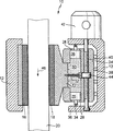
図1は、本発明によるディスクブレーキを半径方向外側から見て、概略的に示す断面図である。
【0019】
実施例の記載
図示の本発明によるディスクブレーキ10は、ブレーキキャリパ12を有しており、このブレーキキャリパ12には2つの摩擦ブレーキライニング16,18が、両ブレーキライニング16,18の間に配置されたブレーキディスク20の両側に挿入されている。ブレーキキャリパ12はいわゆる浮動キャリパとして形成されており、ブレーキディスク20に対して横方向に移動可能である。図面の左側に示された摩擦ブレーキライニング16はブレーキキャリパ12に堅固に受容されており、図面右側に示された摩擦ブレーキライニング18は可動である。図示の断面図ではブレーキキャリパ12は2部分から成っているように示されているが、ブレーキキャリパ12は実際には一体的に構成されており、ブレーキディスク20の周囲に被さっている。
【0020】
可動の摩擦ブレーキライニング18は摩擦ブレーキライニングピストン22を有しており、この摩擦ブレーキライニングピストン22は、ブレーキディスク20に対して横方向に移動可能にマルチプル・ブレーキシリンダ24に受容されている。このマルチプル・ブレーキシリンダ24は摩擦ブレーキライニングピストン22以外に、2つのブレーキ助成ピストン26を有しており、両ブレーキ助成ピストン26は、同軸的に互いに向かい合って位置してブレーキシリンダ24内に配置されている。両ブレーキ助成ピストン26は摩擦ブレーキライニングピストン22に対して横方向に、ひいてはブレーキディスク20に対して平行に移動可能にブレーキシリンダ24内に受容されている。ブレーキ助成ピストン26の外側においてブレーキシリンダ24の半径方向内側に向かって張り出しているリングカラーの形をした外方移動距離制限部28は、ブレーキ助成ピストン26が基本位置を越えて外方に向かってブレーキシリンダ24から外に移動することを阻止している。ブレーキ助成ピストン26は図面では、ディスクブレーキ10の作動時における基本位置で示されている。ブレーキ助成ピストン26は液圧液(ブレーキ液)30を用いて摩擦ブレーキライニングピストン22と接続もしくは作用結合している。液圧液30は制限された不変の容積で、マルチプル・ブレーキシリンダ24内でピストン22,26の間において閉じ込められている。ブレーキ助成ピストン26は摩擦ブレーキライニングピストン22よりも小さな直径を有しており、従って小さなピストン面積を有している。これによってブレーキ助成ピストン26から摩擦ブレーキライニングピストン22への力の伝達もしくは変換が行われる。
【0021】
摩擦ブレーキライニングピストン22は戻しばね32を有している。この戻しばね32は図示及び記載の実施例では、引張りコイルばねとして形成されており、ブレーキシリンダ24内に配置されていて、一端で摩擦ブレーキライニングピストン22に懸吊され、かつ他端でブレーキシリンダ24に懸吊されている。戻しばね32は、ディスクブレーキ10の不作動時には摩擦ブレーキライニング18をブレーキディスク20から持ち上げる。
【0022】
ブレーキ助成ピストン26はその外側にローラ34を有しており、このローラ34で、ブレーキキャリパ12の内側に支持されている。ブレーキキャリパ12は、ブレーキ助成ピストン26のための位置固定の対応受け36を形成しており、この場合両ブレーキ助成ピストン26の対応受け36は、互いに向かい合って位置している。両ブレーキ助成ピストン26は互いに向かって、ひいてはブレーキシリンダ24内において互いに逆方向に移動可能である。
【0023】
マルチプル・ブレーキシリンダ24は可動の摩擦ブレーキライニング18の、ブレーキディスク20とは反対の側に、ひいてはブレーキディスク20の側方に配置されている。ブレーキシリンダ24はブレーキ助成ピストン26と同じ方向に、ひいてはブレーキディスク20に対して平行にかつブレーキディスク20に対して割線方向でブレーキキャリパ12内において移動可能である。ブレーキシリンダ24はブレーキディスク20とは反対側の背側で、ローラ38を介してブレーキキャリパ12の内側に支持されている。
【0024】
ブレーキシリンダ24はスピンドル40によって貫通されており、このスピンドル40は、ブレーキキャリパ12にフランジ結合された電動モータ42によって回転駆動可能である。スピンドル40はブレーキディスク20に対して平行に、かつブレーキシリンダ24の移動方向に配置されている。スピンドル40にはナット44が装着されており、このナット44を介して操作力が軸方向でブレーキシリンダ24に伝達され得る。ナット44は回動を防止されてブレーキシリンダ24の切欠き内に収容されている。スピンドル40とナット44とはスピンドル駆動装置40,44を形成しており、このスピンドル駆動装置40,44を介して電動モータ42を用いてブレーキシリンダ24は、ブレーキディスク20に対して平行にかつブレーキディスク20に対して割線方向で移動可能である。
【0025】
本発明によるディスクブレーキ10の作用を説明するために以下に前提条件を述べておくと、この場合ブレーキディスク20は矢印46の方向で、つまり図面で見て下方に向かって回転する。ディスクブレーキ10を操作するためには、電動モータ42を給電することによってスピンドル駆動装置40,44を介してマルチプル・ブレーキシリンダ24が、ブレーキディスク20の回転方向に移動させられる。ブレーキディスク20の回転方向が矢印46の方向だと仮定すると、つまりブレーキシリンダ24は図面で見て下方に向かって移動させられる。ブレーキシリンダ24の移動方向で見て前方のブレーキ助成ピストン26、つまり対応受け36に支持されているブレーキ助成ピストン26は、ブレーキシリンダ24の移動によって該ブレーキシリンダ24の中に移動させられ、そして液圧液を押し退ける。他方のブレーキ助成ピストン26は、外方移動距離制限部28によってブレーキシリンダ24から外方への移動を阻止され、その結果ブレーキシリンダ24内において運動しない。ブレーキシリンダ24の移動方向で見て前方のブレーキ助成ピストン26はその移動によって、液圧液を摩擦ブレーキライニングピストン22に向かって押し退け、これによって摩擦ブレーキライニングピストン22は、ブレーキディスク20に向かってブレーキシリンダ24から移動させられる。この際に摩擦ブレーキライニングピストン22は可動の摩擦ブレーキライニング18を、ブレーキディスク20の、該摩擦ブレーキライニング18に向けられた側に押し付ける。自体公知の形式でブレーキディスク20に接触している可動の摩擦ブレーキライニング18は、浮動キャリパとして形成されたブレーキキャリパ12をブレーキディスク20に対して横方向に移動させ、ブレーキキャリパ12は固定の摩擦ブレーキライニング16を、ブレーキディスク20の他方の側に押し付ける。そしてブレーキディスク20は制動される。
【0026】
回転するブレーキディスク20は摩擦力を、該ブレーキディスク20に押し付けられる可動の摩擦ブレーキライニング18に加え、この摩擦ブレーキライニング18はブレーキディスク20の回転方向又は割線方向に方向付けられている。回転するブレーキディスク20によって可動の摩擦ブレーキライニング18に加えられる摩擦力は、ブレーキシリンダ24の移動方向に対して平行に方向付けられている。摩擦力は可動の摩擦ブレーキライニング18から、摩擦ブレーキライニングピストン22を介してブレーキシリンダ24に伝達され、そしてこのブレーキシリンダ24を、スピンドル駆動装置40,44によって該ブレーキシリンダ24に加えられる力に加えて、対応受け36に向かって押圧し、この対応受け36は、ブレーキディスク20の回転方向及びブレーキシリンダ24の移動方向で見てブレーキシリンダ24の前に位置している。対応受け36はこれによって、ブレーキシリンダ24の移動方向で見て前方のブレーキ助成ピストン26を、強くブレーキシリンダ24内に押し込み、これにより液圧液30の圧力が上昇し、この圧力は摩擦ブレーキライニングピストン22を介して、ブレーキディスク20への摩擦ブレーキライニング18の圧着力を増大させる。ブレーキディスク20への摩擦ブレーキライニング18の圧着力ひいては本発明によるディスクブレーキ10のブレーキ力はつまり、回転するブレーキディスク20から、該ブレーキディスク20を押圧する可動の摩擦ブレーキライニング18によって加えられる摩擦力によって、増大させられる。その結果ブレーキディスク20への摩擦ブレーキライニング18の圧着力は、部分的にしか電動モータ42からスピンドル駆動装置40,44を介してもたらされず、残りの部分は、回転するブレーキディスク20から該ブレーキディスク20を押圧する可動の摩擦ブレーキライニング18に加えられる摩擦力によってもたらされ、従って本発明によるディスクブレーキ10はブレーキ力助成作用を有している。ブレーキ力助成作用の大きさは、特に、ブレーキディスク20と摩擦ブレーキライニング18との間における摩擦係数と、ブレーキ助成ピストン26のピストン面と摩擦ブレーキライニングピストン22のピストン面との比率とによって左右される。ピストン直径の選択によって、ブレーキ助成作用の大きさを選択することができる。
【0027】
ブレーキディスク20が逆方向(後退走行)に回転すると、ディスクブレーキ10の操作によってマルチプル・ブレーキシリンダ24は、電動モータ42への給電によってスピンドル駆動装置40,44を介して既に述べたように逆方向に、つまり再びブレーキディスク20の回転方向に移動させられる。摩擦ブレーキライニング18の圧着動作及びブレーキ助成作用は、上に述べたのと同様の形式で行われるが、この場合には他方のブレーキ助成ピストン26、つまり今やブレーキシリンダ24の移動方向において前方に位置しているブレーキ助成ピストン26が有効である。従ってブレーキ助成作用はブレーキディスク20の回転方向とは無関係である。両方のブレーキ助成ピストン26の直径が異なっていると、ブレーキディスク20の両回転方向に対して異なった大きさのブレーキ助成作用を、つまり例えば前進走行と後退走行とのために異なった大きさのブレーキ助成作用を選択することができる。
【0028】
液圧液30の代わりに、本発明によるディスクブレーキ10のマルチプル・ブレーキシリンダ24は、弾性質量体、つまり両ブレーキ助成ピストン26のうちの1つによってブレーキシリンダ24の移動時に加えられる圧力を摩擦ブレーキライニングピストン22に伝達する弾性質量体を、有することも可能である。このような弾性質量体のための例としては、シリコン、エラストマ又はEPDM(Ethylen-Propylen-Dien-Elastomer)が挙げられる。
【図面の簡単な説明】
【図1】 本発明によるディスクブレーキを半径方向外側から見て、概略的に示す断面図である。[0001]
BACKGROUND OF THE INVENTION 1. Field of the Invention The present invention relates to a disc brake described in a superordinate conceptual part of claim 1.
[0002]
General purpose disc brakes commonly used today are hydraulically actuated. Such a disc brake has a brake caliper, and in this brake caliper, two friction brake linings are provided on both sides of a brake disc disposed therebetween. In the brake caliper, a friction brake lining piston capable of supplying hydraulic pressure or being hydraulically loaded is received so as to be movable laterally with respect to the brake disc, and one of the friction brake lining pistons is received by the friction brake lining piston. The friction brake lining can be crimped to the brake disc. The other friction brake lining can likewise be pressed against the other side of the brake disc by means of a friction brake lining piston (fixed caliper). It is also known that the brake caliper is formed as a floating caliper so as to be movable laterally with respect to the brake disc. By crimping one friction brake lining against one side of the brake disc, the brake caliper is moved laterally with respect to the brake disc and presses the other friction brake lining against the other side of the brake disc. The brake disc is braked by crimping both friction brake linings.
[0003]
In another known electromechanically actuated disc brake, the friction brake lining can be pressed by means of an electric motor via a rotation / translation / conversion transmission. One example of such an electromechanically operated disc brake is disclosed in WO 96/03301. This known disc brake has an electric motor, and the friction brake lining can be pressed against the brake disc via a spindle driving device which is a rotation / translation / conversion transmission device. The electric motor and the spindle driving device form a known disc brake operating device, which is accommodated in a brake caliper formed as a floating caliper. Known electromechanically actuated disc brakes generally have the following disadvantages. That is, such a disc brake has a large structure and weight based on an electric motor and a rotation / translation / translation transmission device, as compared with a hydraulically operated disc brake. Known electromechanically actuated disc brakes, based on their size, are difficult to install inside the rim of the vehicle wheel, where the disc brake is normally located. In addition, the large weight of the electromechanical disk brake impairs the running characteristics and road holding of the vehicle. This is because the disc brake belongs to a so-called mass not subjected to a spring load, and such mass is desired to be kept small for good running characteristics and good load holding. Further disadvantages of electromechanically actuated disc brakes include the power consumption of electric motors and the associated high loads on the onboard power grid of vehicles equipped with brakes.
[0004]
A common drawback of the known hydraulically actuated disc brakes and electromechanically actuated disc brakes is that such disc brakes do not have a brake force assisting device. For example, a so-called primary shoe (auflaufende Bremsbacke) of a drum brake is known. The primary shoe of the drum brake is additionally pressed against the brake drum from the brake drum that rotates when it is pressed against the brake drum, thereby increasing the braking force.
[0005]
Advantages of the invention The disc brake according to the invention, constructed as described in the characterizing part of claim 1, has a multiple brake cylinder, which is arranged on the side of the brake disc. The brake disc is movable in the secant direction (Sekantenrichtung). The brake cylinder can be guided so as to be movable in the secant direction of the brake disk, for example, using a slide guide or the like. Similarly, it is also possible to mount the brake cylinder so as to be rotatable about a virtual axis of rotation that is offset radially inward or outward relative to the brake cylinder. With such a rotational support format, the brake cylinder is movable along an arcuate track, which extends in the secant direction of the brake disc at least at one or more points and is sufficiently close to the secant direction. Can be considered. In other words, the brake cylinder does not need to be guided movably on a virtual straight line.
[0006]
The concept of multiple brake cylinders is selected because the brake cylinder of the disc brake according to the invention has at least two movably received pistons. The multiple brake cylinder of the disc brake according to the invention has a friction brake lining piston which is movable in a direction perpendicular or nearly perpendicular to the brake disc. By means of a hydraulic pressure load, the friction brake lining piston is moved in the direction of the brake disc, as is known in hydraulically operated disc brakes, and is arranged between the friction brake lining piston and the brake disc. The friction brake lining is pressed against the brake disc, whereby a braking force is generated in a manner known per se.
[0007]
In addition to the friction brake lining piston, the brake cylinder of the disc brake according to the invention has a brake assist piston, which is received in the brake cylinder so as to be movable in the direction of movement of the brake cylinder. . The brake assisting piston is supported by, for example, a position-fixed counterpart provided in a brake caliper of a disc brake. The friction brake lining piston and the brake assisting piston are connected or operatively connected to each other by, for example, hydraulic fluid confined with a certain volume in the brake cylinder.
[0008]
In order to operate the disc brake according to the invention, the brake cylinder of the disc brake is moved in the direction of the rotation of the brake disc of the brake disc and the corresponding receiving of the position of the brake assisting piston. The brake assisting piston supported by the response receiver is moved by the response receiver into a brake cylinder that is moved toward the response receiver. The brake assisting piston moved into the brake cylinder pushes away the hydraulic fluid, thereby pushing the friction brake lining piston out of the brake cylinder. Then, the friction brake lining piston is moved toward the brake disc, and the friction brake lining disposed between the friction brake lining piston and the brake disc is pressed against the brake disc, whereby the friction brake lining brakes the brake disc. To do.
[0009]
The rotating brake disc applies frictional force in the secant direction to the friction brake lining pressed against the brake disc, and this friction brake lining transmits the frictional force to the brake cylinder via the friction brake lining piston. The friction force exerted on the friction brake lining pressed against the brake disc by the rotating brake disc moves the brake cylinder towards the fixed-position counterpart, which in turn causes the brake aid piston to brake more strongly. Push into the cylinder. The pressing force applied from the brake assisting piston to the friction brake lining piston and thus the pressure-bonding force of the friction brake lining against the brake disc is increased, i.e. the braking force of the disc brake according to the invention is increased. Therefore, the disc brake according to the present invention has a brake force assisting device, and only a part of the braking force generated by the pressure-bonding of the friction brake lining to the brake disc is directed toward the position-fixed counterpart. The remaining braking force is generated by the friction force applied to the friction brake lining pressed against the brake disc by the rotating brake disc as described above. By increasing the braking force of the disc brake according to the present invention, the operating force provided to operate the disc brake is reduced, and further, the disc brake according to the present invention is configured to be small and light based on the increased braking force. Can do. Another advantage of the disc brake according to the present invention is the increase in disc brake dynamics, ie, the time required for closing tension and disengagement, based on reduced operating force and reduced weight.
[0010]
Another advantageous configuration of the disc brake according to the invention as claimed in claim 1 is stated in claim 2 and below.
[0011]
According to an advantageous embodiment of the invention, the multiple brake cylinder of the brake disc according to the invention has two brake assist pistons, which are received in the brake cylinders so as to be movable in opposite directions. And supported by opposing counterparts facing each other. Both brake assisting pistons may be arranged coaxially in the brake cylinder, or may be arranged laterally shifted, for example. The outward movement distances of both brake assisting pistons are limited, and both brake assisting pistons cannot move out of the brake cylinder beyond the basic position when the disc brake is inoperative. As described in claim 1, the operation of the disc brake is performed toward the corresponding receiver by the movement of the brake cylinder in the rotation direction of the brake disc. The second brake assisting piston is inactive at the time of braking, and stays at the basic position by the associated outward movement distance limiting unit to limit the volume in the brake cylinder. For example, if the direction of rotation of the brake disc is reversed during reverse travel, the brake cylinder is moved in the direction of the corresponding receiving of the second brake assisting piston in order to operate the disc brake. This moving direction is again the direction of rotation of the brake disc due to the reverse direction of rotation of the brake disc. The braking in the reverse direction of the brake disc is effected in the same manner as described for claim 1 by means of a second brake assist piston, in which case the first brake assist piston is active in an inactive manner. Instead, it is in contact with the corresponding outward movement distance limiter. By providing a second brake assisting piston movable in the opposite direction, the disc brake according to the invention has a braking force assisting device for both directions of rotation of the brake disc, the disc brake being independent of the direction of rotation. That is, it functions in both directions of rotation.
[0012]
The brake force assisting device can make different selections for both directions of rotation of the brake disc by selecting the piston surfaces of both brake assisting pistons to different sizes. If both brake assisting pistons have piston surfaces of the same size, the disc brake according to the present invention is the same for both directions of rotation of the brake disc.
[0013]
The height of the brake force assisting device can be selected by selecting the friction brake lining piston and the piston surface of the brake force assisting device to have different sizes or equal sizes. According to the fifth aspect, the piston surface of the brake assisting piston is smaller than the piston surface of the friction brake lining piston. If it becomes like this, the effect | action of a braking force assistance apparatus will be increased.
[0014]
The disc brake according to the invention is in particular provided for electromechanical operation using an electric motor (claim 7).
[0015]
Based on the brake force assisting device, a small and light electric motor with a small moving mass can be selected. Similarly, the rotation / translation / conversion transmission device can also be constructed as a lightweight structure. The brake force assisting device for a disc brake according to the present invention can reduce the movable mass provided for its operation, thereby enhancing the dynamic characteristics of the disc brake. Furthermore, an electric motor with a relatively small output is sufficient for operation, and such an electric motor consumes less power and can reduce the on-board power supply network of a vehicle equipped with a disc brake according to the present invention.
[0016]
According to the configuration of claim 8, an elastic mass body is used instead of the piston hydraulic fluid in order to transmit the motion of the brake assisting piston to the friction brake lining piston. The elastic mass has the advantage that the piston seal can be omitted and there is no risk of hydraulic fluid loss.
[0017]
Next, embodiments of the present invention will be described with reference to the drawings.
[0018]
FIG. 1 is a sectional view schematically showing a disc brake according to the present invention as seen from the outside in the radial direction.
[0019]
The
[0020]
The movable
[0021]
The friction brake lining piston 22 has a return spring 32. In the embodiment shown and described, this return spring 32 is formed as a tension coil spring and is arranged in the
[0022]
The
[0023]
The
[0024]
The
[0025]
In order to explain the operation of the
[0026]
The
[0027]
When the
[0028]
Instead of hydraulic fluid 30, the
[Brief description of the drawings]
FIG. 1 is a cross-sectional view schematically showing a disc brake according to the present invention when viewed from the outside in a radial direction.
Claims (8)
Applications Claiming Priority (2)
| Application Number | Priority Date | Filing Date | Title |
|---|---|---|---|
| DE10105540A DE10105540A1 (en) | 2001-02-07 | 2001-02-07 | disc brake |
| PCT/DE2002/000162 WO2002063177A1 (en) | 2001-02-07 | 2002-01-19 | Disc brake |
Publications (2)
| Publication Number | Publication Date |
|---|---|
| JP2004518094A JP2004518094A (en) | 2004-06-17 |
| JP4170761B2 true JP4170761B2 (en) | 2008-10-22 |
Family
ID=7673164
Family Applications (1)
| Application Number | Title | Priority Date | Filing Date |
|---|---|---|---|
| JP2002562889A Expired - Fee Related JP4170761B2 (en) | 2001-02-07 | 2002-01-19 | Disc brake |
Country Status (5)
| Country | Link |
|---|---|
| US (1) | US6926126B2 (en) |
| EP (1) | EP1360429B1 (en) |
| JP (1) | JP4170761B2 (en) |
| DE (2) | DE10105540A1 (en) |
| WO (1) | WO2002063177A1 (en) |
Families Citing this family (16)
| Publication number | Priority date | Publication date | Assignee | Title |
|---|---|---|---|---|
| US7040420B2 (en) | 1994-10-14 | 2006-05-09 | Weatherford/Lamb, Inc. | Methods and apparatus for cementing drill strings in place for one pass drilling and completion of oil and gas wells |
| US7228901B2 (en) | 1994-10-14 | 2007-06-12 | Weatherford/Lamb, Inc. | Method and apparatus for cementing drill strings in place for one pass drilling and completion of oil and gas wells |
| US7311148B2 (en) | 1999-02-25 | 2007-12-25 | Weatherford/Lamb, Inc. | Methods and apparatus for wellbore construction and completion |
| US7334650B2 (en) | 2000-04-13 | 2008-02-26 | Weatherford/Lamb, Inc. | Apparatus and methods for drilling a wellbore using casing |
| US7730965B2 (en) | 2002-12-13 | 2010-06-08 | Weatherford/Lamb, Inc. | Retractable joint and cementing shoe for use in completing a wellbore |
| US7303022B2 (en) | 2002-10-11 | 2007-12-04 | Weatherford/Lamb, Inc. | Wired casing |
| USRE42877E1 (en) | 2003-02-07 | 2011-11-01 | Weatherford/Lamb, Inc. | Methods and apparatus for wellbore construction and completion |
| US7360594B2 (en) | 2003-03-05 | 2008-04-22 | Weatherford/Lamb, Inc. | Drilling with casing latch |
| WO2004079150A2 (en) | 2003-03-05 | 2004-09-16 | Weatherford/Lamb, Inc. | Full bore lined wellbores |
| US7264067B2 (en) | 2003-10-03 | 2007-09-04 | Weatherford/Lamb, Inc. | Method of drilling and completing multiple wellbores inside a single caisson |
| DE10347792A1 (en) * | 2003-10-14 | 2005-05-12 | Bosch Gmbh Robert | wheel brake |
| US20050216160A1 (en) * | 2004-03-23 | 2005-09-29 | Delphi Technologies Inc. | Method for detecting electric-mechanical-brake pad drag and/or calculating actuator efficiency |
| CA2538196C (en) | 2005-02-28 | 2011-10-11 | Weatherford/Lamb, Inc. | Deep water drilling with casing |
| DE102005049786A1 (en) * | 2005-10-18 | 2007-04-19 | Knorr-Bremse Systeme für Nutzfahrzeuge GmbH | Disc brake with electromotive actuator, preferably in self-reinforcing design |
| DE102008061347B3 (en) * | 2008-12-10 | 2010-04-01 | Knorr-Bremse Systeme für Nutzfahrzeuge GmbH | Disk brake for heavy goods vehicle, has electrical motor actuator, which operates on tightening device with brake calipers for tightening of two brake pads toward brake disk |
| ES2551655B1 (en) * | 2015-07-10 | 2016-06-20 | Lucio Antonio ORTEGA MORENO | PROGRESSIVE DOSING MECHANISM OF THE BRAKING |
Family Cites Families (12)
| Publication number | Priority date | Publication date | Assignee | Title |
|---|---|---|---|---|
| FR1370811A (en) * | 1963-07-18 | 1964-08-28 | Ferodo Sa | Improvements to disc brakes and similar applications |
| US3277982A (en) * | 1964-11-23 | 1966-10-11 | Gen Motors Corp | Self-energizing disc brake |
| FR1518748A (en) * | 1967-01-16 | 1968-03-29 | Ferodo Sa | Disc brake and braking installation, in particular for motor vehicles, comprising such brakes |
| DE1808123A1 (en) * | 1968-11-09 | 1970-05-27 | Porsche Kg | Self-amplifying servo braking device for disc brake systems, especially for dual-circuit disc brake systems of motor vehicles |
| SE344036B (en) * | 1969-11-19 | 1972-03-27 | E Gelhaar | |
| FR2146160B1 (en) * | 1971-07-22 | 1975-10-10 | Millon Auguste | |
| DE3441128A1 (en) * | 1984-11-10 | 1986-05-15 | FAG Kugelfischer Georg Schäfer KGaA, 8720 Schweinfurt | Hydraulic brake system with power assistance |
| DE3525007A1 (en) | 1985-07-12 | 1987-01-15 | Knorr Bremse Ag | CLAMPING CYLINDER FOR FRICTION BRAKES |
| FR2648098A1 (en) * | 1989-06-09 | 1990-12-14 | Mebtoul Ali | Auto-assisted brake with independent pressure distribution to each wheel and involving an anti-lock system if necessary |
| US5036960A (en) * | 1990-05-17 | 1991-08-06 | General Motors Corporation | Apparatus and method of automotive brake with booster piston |
| DE19511287B4 (en) * | 1994-07-21 | 2004-05-06 | Continental Teves Ag & Co. Ohg | Electromechanically actuated disc brake |
| DE19511811B4 (en) * | 1995-03-30 | 2005-10-06 | Lucas Industries P.L.C., Solihull | Electronically controllable braking system for land vehicles and method for their operation |
-
2001
- 2001-02-07 DE DE10105540A patent/DE10105540A1/en not_active Withdrawn
-
2002
- 2002-01-19 EP EP02706604A patent/EP1360429B1/en not_active Expired - Lifetime
- 2002-01-19 DE DE2002501287 patent/DE50201287D1/en not_active Expired - Lifetime
- 2002-01-19 WO PCT/DE2002/000162 patent/WO2002063177A1/en not_active Ceased
- 2002-01-19 US US10/467,327 patent/US6926126B2/en not_active Expired - Fee Related
- 2002-01-19 JP JP2002562889A patent/JP4170761B2/en not_active Expired - Fee Related
Also Published As
| Publication number | Publication date |
|---|---|
| DE50201287D1 (en) | 2004-11-18 |
| US20040112693A1 (en) | 2004-06-17 |
| DE10105540A1 (en) | 2002-08-29 |
| US6926126B2 (en) | 2005-08-09 |
| WO2002063177A1 (en) | 2002-08-15 |
| EP1360429A1 (en) | 2003-11-12 |
| JP2004518094A (en) | 2004-06-17 |
| EP1360429B1 (en) | 2004-10-13 |
Similar Documents
| Publication | Publication Date | Title |
|---|---|---|
| US11719296B2 (en) | Brake system with torque distributing assembly | |
| JP4838506B2 (en) | Wheel brake | |
| CN102326010B (en) | Electromechanical devices for driving and/or braking shafts | |
| JP2004518094A (en) | Disc brake | |
| EP1105658B1 (en) | Multiple disk brake system with integrated parking brake | |
| JP5095905B2 (en) | Disc brake | |
| US6142265A (en) | Arrangement for operating a brake of a vehicle | |
| CN210661128U (en) | Commercial vehicle electronic mechanical brake with clamping force retaining function | |
| JP2003014015A (en) | Electric parking brake | |
| JP2011149536A (en) | Feed screw device equipped with lock prevention mechanism | |
| JPH0617856A (en) | Friction brake used in vehicle and method of braking vehicle | |
| WO1998006608A2 (en) | Electro-mechanical actuation mechanism for disc brake assembly | |
| CN115875383B (en) | Brake device for vehicle | |
| KR100760357B1 (en) | Brake device of wheel type industrial vehicle | |
| KR102265283B1 (en) | Brake disc unit for vehicles | |
| JPH09250579A (en) | Electric disc brake | |
| CN114396439A (en) | Wire control actuator | |
| KR20110136927A (en) | Car Disc Brake | |
| KR970007712B1 (en) | Brake system of a car | |
| KR100398257B1 (en) | drum break for vehicle | |
| KR100655326B1 (en) | Brake system of industrial vehicle | |
| JP2001124118A (en) | Disc brake | |
| KR100534971B1 (en) | Noise reducing apparatus of brake | |
| RU2153609C1 (en) | Braking device with wear compensator | |
| KR200213972Y1 (en) | Braking apparatus for armored vehicle |
Legal Events
| Date | Code | Title | Description |
|---|---|---|---|
| A621 | Written request for application examination |
Free format text: JAPANESE INTERMEDIATE CODE: A621 Effective date: 20050118 |
|
| A131 | Notification of reasons for refusal |
Free format text: JAPANESE INTERMEDIATE CODE: A131 Effective date: 20071102 |
|
| A601 | Written request for extension of time |
Free format text: JAPANESE INTERMEDIATE CODE: A601 Effective date: 20080204 |
|
| A602 | Written permission of extension of time |
Free format text: JAPANESE INTERMEDIATE CODE: A602 Effective date: 20080212 |
|
| A601 | Written request for extension of time |
Free format text: JAPANESE INTERMEDIATE CODE: A601 Effective date: 20080303 |
|
| A602 | Written permission of extension of time |
Free format text: JAPANESE INTERMEDIATE CODE: A602 Effective date: 20080310 |
|
| A521 | Request for written amendment filed |
Free format text: JAPANESE INTERMEDIATE CODE: A523 Effective date: 20080402 |
|
| TRDD | Decision of grant or rejection written | ||
| A01 | Written decision to grant a patent or to grant a registration (utility model) |
Free format text: JAPANESE INTERMEDIATE CODE: A01 Effective date: 20080709 |
|
| A01 | Written decision to grant a patent or to grant a registration (utility model) |
Free format text: JAPANESE INTERMEDIATE CODE: A01 |
|
| A61 | First payment of annual fees (during grant procedure) |
Free format text: JAPANESE INTERMEDIATE CODE: A61 Effective date: 20080807 |
|
| FPAY | Renewal fee payment (event date is renewal date of database) |
Free format text: PAYMENT UNTIL: 20110815 Year of fee payment: 3 |
|
| R150 | Certificate of patent or registration of utility model |
Free format text: JAPANESE INTERMEDIATE CODE: R150 |
|
| FPAY | Renewal fee payment (event date is renewal date of database) |
Free format text: PAYMENT UNTIL: 20110815 Year of fee payment: 3 |
|
| FPAY | Renewal fee payment (event date is renewal date of database) |
Free format text: PAYMENT UNTIL: 20120815 Year of fee payment: 4 |
|
| FPAY | Renewal fee payment (event date is renewal date of database) |
Free format text: PAYMENT UNTIL: 20120815 Year of fee payment: 4 |
|
| FPAY | Renewal fee payment (event date is renewal date of database) |
Free format text: PAYMENT UNTIL: 20130815 Year of fee payment: 5 |
|
| R250 | Receipt of annual fees |
Free format text: JAPANESE INTERMEDIATE CODE: R250 |
|
| R250 | Receipt of annual fees |
Free format text: JAPANESE INTERMEDIATE CODE: R250 |
|
| LAPS | Cancellation because of no payment of annual fees |