JP4320331B2 - 駆動電圧制御装置を備えた移動通信端末機及びその駆動電圧制御方法 - Google Patents
駆動電圧制御装置を備えた移動通信端末機及びその駆動電圧制御方法 Download PDFInfo
- Publication number
- JP4320331B2 JP4320331B2 JP2006068127A JP2006068127A JP4320331B2 JP 4320331 B2 JP4320331 B2 JP 4320331B2 JP 2006068127 A JP2006068127 A JP 2006068127A JP 2006068127 A JP2006068127 A JP 2006068127A JP 4320331 B2 JP4320331 B2 JP 4320331B2
- Authority
- JP
- Japan
- Prior art keywords
- voltage
- power
- level
- unit
- signal
- Prior art date
- Legal status (The legal status is an assumption and is not a legal conclusion. Google has not performed a legal analysis and makes no representation as to the accuracy of the status listed.)
- Expired - Fee Related
Links
Images




Classifications
-
- H—ELECTRICITY
- H03—ELECTRONIC CIRCUITRY
- H03F—AMPLIFIERS
- H03F1/00—Details of amplifiers with only discharge tubes, only semiconductor devices or only unspecified devices as amplifying elements
- H03F1/02—Modifications of amplifiers to raise the efficiency, e.g. gliding Class A stages, use of an auxiliary oscillation
- H03F1/0205—Modifications of amplifiers to raise the efficiency, e.g. gliding Class A stages, use of an auxiliary oscillation in transistor amplifiers
- H03F1/0211—Modifications of amplifiers to raise the efficiency, e.g. gliding Class A stages, use of an auxiliary oscillation in transistor amplifiers with control of the supply voltage or current
- H03F1/0216—Continuous control
- H03F1/0233—Continuous control by using a signal derived from the output signal, e.g. bootstrapping the voltage supply
Landscapes
- Engineering & Computer Science (AREA)
- Power Engineering (AREA)
- Transmitters (AREA)
- Transceivers (AREA)
Description

202:高周波処理部
204:電力増幅部
206:高電力検出部
208:検出電圧レベル変換部
210:可変駆動電圧出力部
Claims (7)
- 送信信号を電力増幅してアンテナへ出力する電力増幅部を備えた移動通信端末機において、
前記電力増幅部の出力電力が所定の臨界値を超えたときに、当該超過電力相当の電圧のレベル信号を出力する高電力検出部と、
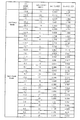
該高電力検出部から出力され得るレベル信号に対応させて、前記電力増幅部に適切なレベルの駆動電圧が提供される電圧レベルを予め記憶したテーブルを備え、該テーブルを利用して、前記レベル信号を所定の電圧レベルにシフトさせたレベルシフト信号を出力する検出電圧レベル変換部と、
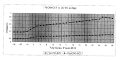
前記レベルシフト信号を入力電圧として所定倍の電圧にコンバートし、該コンバート電圧とバッテリによる電圧とを比較して、前記コンバート電圧の方が小さい場合は前記バッテリによる電圧を駆動電圧として前記電力増幅部に提供し、前記コンバート電圧の方が大きい場合は該コンバート電圧を駆動電圧として前記電力増幅部に提供する可変駆動電圧出力部と、
を含んで構成される駆動電圧制御装置、を備えたことを特徴とする移動通信端末機。 - 送信信号を電力増幅してアンテナへ出力する電力増幅部を備えた移動通信端末機において、
前記電力増幅部の出力電力が所定の臨界値を超えたときに、当該超過電力相当の電圧のレベル信号を出力する高電力検出部と、
所定の直流電圧及び抵抗の値によって、前記電力増幅部に適切なレベルの駆動電圧が提供される電圧レベルに、前記レベル信号の電圧をシフトさせる分圧回路を備え、該分圧回路を利用して前記レベル信号を所定の電圧レベルにシフトさせたレベルシフト信号を出力する検出電圧レベル変換部と、
前記レベルシフト信号を入力電圧として所定倍の電圧にコンバートし、該コンバート電圧とバッテリによる電圧とを比較して、前記コンバート電圧の方が小さい場合は前記バッテリによる電圧を駆動電圧として前記電力増幅部に提供し、前記コンバート電圧の方が大きい場合は該コンバート電圧による駆動電圧を前記電力増幅部に提供する可変駆動電圧出力部と、
を含んで構成される駆動電圧制御装置、を備えたことを特徴とする移動通信端末機。 - 前記検出電圧レベル変換部によるレベルシフト信号を受ける制御部をもつことを特徴とする請求項1又は請求項2に記載の移動通信端末機。
- 前記高電力検出部は、前記出力電力を検知するためのモジュールを有することを特徴とする請求項1又は請求項2に記載の移動通信端末機。
- 送信信号を電力増幅してアンテナから無線伝送する増幅段階と、
前記増幅した送信信号の電力が所定の臨界値を超えたときにその臨界値超過電力相当の電圧を発生する高電力検出段階と、
該高電力検出段階で発生され得る臨界値超過電力相当の電圧に対応させて、前記送信信号の電力増幅に適切なレベルの駆動電圧が提供される電圧レベルを予め記憶したテーブルを利用して、前記臨界値超過電力相当の電圧を所定の電圧レベルにシフトさせるレベルシフト段階と、
前記レベルシフトさせた電圧を所定倍の電圧にコンバートするコンバート段階と、
該コンバート段階でコンバートしたコンバート電圧をバッテリによる電圧と比較して、前記コンバート電圧の方が小さい場合は前記バッテリによる電圧を前記送信信号の電力増幅に用いる駆動電圧とし、前記コンバート電圧の方が大きい場合は該コンバート電圧を前記送信信号の電力増幅に用いる駆動電圧とする比較段階と、
を含むことを特徴とする移動通信端末機の駆動電圧制御方法。 - 送信信号を電力増幅してアンテナから無線伝送する増幅段階と、
前記増幅した送信信号の電力が所定の臨界値を超えたときにその臨界値超過電力相当の電圧を発生する高電力検出段階と、
所定の直流電圧及び抵抗の値によって、前記送信信号の電力増幅に適切なレベルの駆動電圧が提供される電圧レベルに、前記臨界値超過電力相当の電圧をシフトさせる分圧回路を利用して、前記臨界値超過電力相当の電圧を所定の電圧レベルにシフトさせるレベルシフト段階と、
前記レベルシフトさせた電圧を所定倍の電圧にコンバートするコンバート段階と、
該コンバート段階でコンバートしたコンバート電圧をバッテリによる電圧と比較して、前記コンバート電圧の方が小さい場合は前記バッテリによる電圧を前記送信信号の電力増幅に用いる駆動電圧とし、前記コンバート電圧の方が大きい場合は該コンバート電圧を前記送信信号の電力増幅に用いる駆動電圧とする比較段階と、
を含むことを特徴とする移動通信端末機の駆動電圧制御方法。 - 前記レベルシフト段階は、前記所定の電圧レベルにシフトさせた電圧を、前記送信信号を生成する制御部に提供する段階を含むことを特徴とする請求項5又は請求項6に記載の移動通信端末機の駆動電圧制御方法。
Applications Claiming Priority (2)
| Application Number | Priority Date | Filing Date | Title |
|---|---|---|---|
| KR1020050020738A KR20060099343A (ko) | 2005-03-11 | 2005-03-11 | 전력 증폭기의 구동 전압 제어 장치 |
| KR1020050033338A KR20060111047A (ko) | 2005-04-21 | 2005-04-21 | 전력 증폭기의 구동 전압 제어 장치 |
Publications (2)
| Publication Number | Publication Date |
|---|---|
| JP2006254468A JP2006254468A (ja) | 2006-09-21 |
| JP4320331B2 true JP4320331B2 (ja) | 2009-08-26 |
Family
ID=36794408
Family Applications (1)
| Application Number | Title | Priority Date | Filing Date |
|---|---|---|---|
| JP2006068127A Expired - Fee Related JP4320331B2 (ja) | 2005-03-11 | 2006-03-13 | 駆動電圧制御装置を備えた移動通信端末機及びその駆動電圧制御方法 |
Country Status (3)
| Country | Link |
|---|---|
| US (1) | US7574182B2 (ja) |
| EP (1) | EP1708358A3 (ja) |
| JP (1) | JP4320331B2 (ja) |
Families Citing this family (4)
| Publication number | Priority date | Publication date | Assignee | Title |
|---|---|---|---|---|
| US20090137217A1 (en) * | 2007-11-27 | 2009-05-28 | Huang Chung-Er | Communication transmission system and power detection method thereof |
| JP2016136702A (ja) * | 2015-01-23 | 2016-07-28 | 富士通株式会社 | 無線通信装置、無線通信方法、及び無線通信プログラム |
| US9837972B2 (en) * | 2015-12-30 | 2017-12-05 | Skyworks Solutions, Inc. | Multi-mode power amplifier module |
| CN107634725B (zh) * | 2017-08-31 | 2021-09-10 | 深圳市远望谷信息技术股份有限公司 | 一种提升功率放大器效率的方法及装置 |
Family Cites Families (20)
| Publication number | Priority date | Publication date | Assignee | Title |
|---|---|---|---|---|
| US4523155A (en) * | 1983-05-04 | 1985-06-11 | Motorola, Inc. | Temperature compensated automatic output control circuitry for RF signal power amplifiers with wide dynamic range |
| US4636741A (en) * | 1985-11-01 | 1987-01-13 | Motorola, Inc. | Multi-level power amplifying circuitry for portable radio transceivers |
| JPH03198407A (ja) * | 1989-12-26 | 1991-08-29 | Mitsubishi Electric Corp | 線形増幅器 |
| JPH03283717A (ja) | 1990-03-30 | 1991-12-13 | Oki Electric Ind Co Ltd | 無線送信機の電力増幅装置 |
| JP2690595B2 (ja) | 1990-04-20 | 1997-12-10 | 沖電気工業株式会社 | 電力制御回路 |
| US5182527A (en) * | 1990-03-30 | 1993-01-26 | Oki Electric Industry Co., Ltd. | Power amplifying apparatus for wireless transmitter |
| JPH06334541A (ja) * | 1993-05-25 | 1994-12-02 | Sony Corp | 無線送信機 |
| US5886575A (en) * | 1997-09-30 | 1999-03-23 | Motorola, Inc. | Apparatus and method for amplifying a signal |
| JP3129272B2 (ja) | 1998-01-28 | 2001-01-29 | 日本電気株式会社 | 半導体装置とその製造装置および製造方法 |
| US6173163B1 (en) * | 1998-06-30 | 2001-01-09 | Ericsson Inc. | Switched sampling systems and methods for monitoring radio transmit power |
| KR20000046113A (ko) | 1998-12-31 | 2000-07-25 | 김영환 | 휴대 전화기의 배터리 절전 장치 및 방법 |
| JP2001320288A (ja) | 2000-03-03 | 2001-11-16 | Matsushita Electric Ind Co Ltd | 電源電圧制御装置及び電源電圧制御方法 |
| KR200208301Y1 (ko) | 2000-07-14 | 2000-12-15 | 엄향련 | 미드솔 및 아웃솔 성형용 금형의 가압 개폐장치 |
| JP2002314345A (ja) | 2001-04-16 | 2002-10-25 | Sony Corp | 高周波増幅回路およびこれを用いた無線通信装置 |
| JP2003008365A (ja) | 2001-04-16 | 2003-01-10 | Matsushita Electric Ind Co Ltd | 電力増幅用回路、電力増幅用回路の制御方法、及び携帯端末装置 |
| US6639471B2 (en) * | 2001-04-16 | 2003-10-28 | Matsushita Electric Industrial Co., Ltd. | Power amplifier circuit, control method for power amplifier circuit, and portable terminal apparatus for mobile communication |
| US8353932B2 (en) * | 2005-09-30 | 2013-01-15 | Jackson Roger P | Polyaxial bone anchor assembly with one-piece closure, pressure insert and plastic elongate member |
| JP3809777B2 (ja) * | 2001-05-30 | 2006-08-16 | ソニー株式会社 | 電力増幅器 |
| JP2004363867A (ja) | 2003-06-04 | 2004-12-24 | Alps Electric Co Ltd | 送信回路 |
| US8377102B2 (en) * | 2003-06-18 | 2013-02-19 | Roger P. Jackson | Polyaxial bone anchor with spline capture connection and lower pressure insert |
-
2006
- 2006-03-09 EP EP06004861A patent/EP1708358A3/en not_active Withdrawn
- 2006-03-13 US US11/373,289 patent/US7574182B2/en not_active Expired - Fee Related
- 2006-03-13 JP JP2006068127A patent/JP4320331B2/ja not_active Expired - Fee Related
Also Published As
| Publication number | Publication date |
|---|---|
| US7574182B2 (en) | 2009-08-11 |
| JP2006254468A (ja) | 2006-09-21 |
| EP1708358A3 (en) | 2006-12-06 |
| US20060202889A1 (en) | 2006-09-14 |
| EP1708358A2 (en) | 2006-10-04 |
Similar Documents
| Publication | Publication Date | Title |
|---|---|---|
| EP1480332B1 (en) | Integratable, voltage-controlled rf power amplifier | |
| JP5275590B2 (ja) | 増幅回路 | |
| US20110241783A1 (en) | Detector circuit and system for a wireless communication | |
| EP1713176A1 (en) | Power amplifier unit, communication terminal and control method of power amplifier unit | |
| JP2005175561A (ja) | 高周波電力増幅回路用電源回路および電源用半導体集積回路並びに電源用電子部品 | |
| KR20080021828A (ko) | 선형 전력 증폭기용 자동 바이어스 제어 회로 | |
| US8587380B2 (en) | Saturation protection of a regulated voltage | |
| JP2006013753A (ja) | 無線通信システムおよび半導体集積回路 | |
| TW518820B (en) | Matching apparatus | |
| US20050285682A1 (en) | Amplifying circuit with variable supply voltage | |
| US7061326B2 (en) | Transmission circuit capable of efficiently operating a power amplifier | |
| JP6269423B2 (ja) | 電力増幅装置および電力増幅方法 | |
| EP2482450A2 (en) | Bias control for reducing amplifier power consumption and maintaining linearity | |
| JP2006254468A (ja) | 駆動電圧制御装置を備えた移動通信端末機及びその駆動電圧制御方法 | |
| JP2005079967A (ja) | 高周波電力増幅器及びこれを使用した無線通信機器 | |
| JP2001203536A (ja) | 検波回路及び送信装置 | |
| JP3976567B2 (ja) | 電力増幅装置及びそれを用いた通信装置 | |
| US11411537B2 (en) | D-class amplifier circuit and audio amplifying method | |
| US8063513B2 (en) | Power source and method for controlling operational power | |
| EP1553695B1 (en) | Start signal output circuit | |
| KR20060099343A (ko) | 전력 증폭기의 구동 전압 제어 장치 | |
| EP1630965A1 (en) | Power amplifying circuit in mobile terminal | |
| US20050062538A1 (en) | RF power amplifier having an operating current measuring device | |
| KR20060111047A (ko) | 전력 증폭기의 구동 전압 제어 장치 | |
| KR20020094628A (ko) | 가변 동작점 전력 증폭기 |
Legal Events
| Date | Code | Title | Description |
|---|---|---|---|
| A977 | Report on retrieval |
Free format text: JAPANESE INTERMEDIATE CODE: A971007 Effective date: 20081120 |
|
| A131 | Notification of reasons for refusal |
Free format text: JAPANESE INTERMEDIATE CODE: A131 Effective date: 20081202 |
|
| A521 | Written amendment |
Free format text: JAPANESE INTERMEDIATE CODE: A523 Effective date: 20090302 |
|
| TRDD | Decision of grant or rejection written | ||
| A01 | Written decision to grant a patent or to grant a registration (utility model) |
Free format text: JAPANESE INTERMEDIATE CODE: A01 Effective date: 20090507 |
|
| A01 | Written decision to grant a patent or to grant a registration (utility model) |
Free format text: JAPANESE INTERMEDIATE CODE: A01 |
|
| A61 | First payment of annual fees (during grant procedure) |
Free format text: JAPANESE INTERMEDIATE CODE: A61 Effective date: 20090601 |
|
| FPAY | Renewal fee payment (event date is renewal date of database) |
Free format text: PAYMENT UNTIL: 20120605 Year of fee payment: 3 |
|
| R150 | Certificate of patent or registration of utility model |
Free format text: JAPANESE INTERMEDIATE CODE: R150 |
|
| FPAY | Renewal fee payment (event date is renewal date of database) |
Free format text: PAYMENT UNTIL: 20130605 Year of fee payment: 4 |
|
| R250 | Receipt of annual fees |
Free format text: JAPANESE INTERMEDIATE CODE: R250 |
|
| R250 | Receipt of annual fees |
Free format text: JAPANESE INTERMEDIATE CODE: R250 |
|
| R250 | Receipt of annual fees |
Free format text: JAPANESE INTERMEDIATE CODE: R250 |
|
| R250 | Receipt of annual fees |
Free format text: JAPANESE INTERMEDIATE CODE: R250 |
|
| LAPS | Cancellation because of no payment of annual fees |