JP4332018B2 - Dispenser - Google Patents
Dispenser Download PDFInfo
- Publication number
- JP4332018B2 JP4332018B2 JP2003390936A JP2003390936A JP4332018B2 JP 4332018 B2 JP4332018 B2 JP 4332018B2 JP 2003390936 A JP2003390936 A JP 2003390936A JP 2003390936 A JP2003390936 A JP 2003390936A JP 4332018 B2 JP4332018 B2 JP 4332018B2
- Authority
- JP
- Japan
- Prior art keywords
- pressing
- pressing head
- container
- dispenser
- head
- Prior art date
- Legal status (The legal status is an assumption and is not a legal conclusion. Google has not performed a legal analysis and makes no representation as to the accuracy of the status listed.)
- Expired - Fee Related
Links
- 210000003813 thumb Anatomy 0.000 claims description 4
- 239000000344 soap Substances 0.000 description 2
- 210000003811 finger Anatomy 0.000 description 1
- 239000007788 liquid Substances 0.000 description 1
- 239000006210 lotion Substances 0.000 description 1
- 238000005086 pumping Methods 0.000 description 1
- -1 rinse Substances 0.000 description 1
- 239000002453 shampoo Substances 0.000 description 1
- XLYOFNOQVPJJNP-UHFFFAOYSA-N water Substances O XLYOFNOQVPJJNP-UHFFFAOYSA-N 0.000 description 1
Images




Landscapes
- Containers And Packaging Bodies Having A Special Means To Remove Contents (AREA)
- Closures For Containers (AREA)
Description
本発明は、容器内の内容物を適量噴出させるのに好適なディスペンサに関するものであり、該ディスペンサの使い易さの改善を図ろうとするものである。 The present invention relates to a dispenser suitable for ejecting an appropriate amount of contents in a container, and intends to improve the ease of use of the dispenser.
シャンプーやリンス、化粧水あるいは液体石鹸等を入れた容器ではそれそのものを持ち上げることをせず押圧ヘッドを押圧するのみで内容物を適量注出することができるようにディスペンサを備えたものが多数存在している(例えば特許文献1参照)。
ところで、ハンドソープ等の内容物を入れておく比較的小型の容器に装着されるディスペンサは容器のサイズに合わせてサイズの小型化がなされていることから、内容物を噴出させる際にヘッド部において手が滑り易いという不都合があり(とくに力の弱い幼児や老人にとっては顕著)その改善が望まれていた。 By the way, since the dispenser attached to a relatively small container for storing contents such as a hand soap is reduced in size according to the size of the container, when the contents are jetted, There was an inconvenience that the hand was slippery (especially noticeable for weak children and elderly people), and the improvement was desired.
本発明の課題は、ディスペンサのサイズにかかわりなしにしっかりと把持した状態で押圧ヘッドを押圧して内容物を適量噴出できる新規なディスペンサを提案するところにある。 An object of the present invention is to propose a novel dispenser capable of ejecting an appropriate amount of contents by pressing a pressing head while firmly grasping regardless of the size of the dispenser.
本発明は、容器の口部に固定保持されるベースキャップと、このベースキャップの下面に垂下され容器内の内容物を吸引、加圧、圧送するポンプと、このポンプを作動させて内容物を外界に向けて噴出させるノズル付きの押圧ヘッドを備えたディスペンサであって、
前記押圧ヘッドに、該押圧ヘッドにつながり押圧面積の拡大を図るとともにベースキャップに至るまでの領域若しくは容器の肩部下端域に至るまでの領域を覆い該押圧ヘッドの押し込みに帯同してスライドするカバーを設け、
該カバーに、押圧ヘッドのノズルの直下側壁に設けられ、親指をあてがって押圧ヘッドを把持したままで該押圧ヘッドの押し込みを可能とした凹部を形成したことを特徴とするディスペンサである。
The present invention includes a base cap that is fixedly held at the mouth of a container, a pump that is suspended from the lower surface of the base cap and sucks, pressurizes, and pumps the contents in the container, and operates the pump to remove the contents. A dispenser having a pressure head with a nozzle that ejects toward the outside world,
A cover that is connected to the pressing head to increase the pressing area and covers the area extending to the base cap or the lower end area of the shoulder portion of the container, and sliding along with the pressing of the pressing head. Provided,
The dispenser is characterized in that the cover is provided with a concave portion provided on a side wall immediately below the nozzle of the pressing head, which allows the pressing head to be pushed in while holding the pressing head with a thumb .
また、前記カバーは、ベースキャップ若しくは容器に係合して押圧ヘッドに負荷される不用意な荷重による内容物の漏洩を防止するストッパーを備えることができる。 In addition, the cover may include a stopper that prevents leakage of contents due to an inadvertent load that is engaged with the base cap or the container and is applied to the pressing head.
押圧ヘッドにおける押圧面積が拡大され、それを握った状態で内容物を噴出させることが可能で手が滑るような不具合がない。 The pressing area of the pressing head is enlarged, and the contents can be ejected while grasping the pressing area.
押圧ヘッドからベースキャップまで、あるいは押圧ヘッドから容器の肩部下端までカバーで覆われるので容器内に水等が侵入することはなく内容物の品質が安定的に保たれる。 Since the cover is covered from the pressing head to the base cap or from the pressing head to the lower end of the shoulder of the container, water or the like does not enter the container, and the quality of the contents is stably maintained.
以下、図面を参照して本発明をより具体的に説明する。 Hereinafter, the present invention will be described more specifically with reference to the drawings.
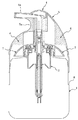
図1は本発明に従うディスペンサの実施の形態を示したものであり、図2はディスペンサの使用状況を示した図である。 FIG. 1 shows an embodiment of a dispenser according to the present invention, and FIG. 2 is a view showing a use state of the dispenser.
図における1は内容物を収納する容器、2は容器の口部にねじ止めによって固定保持される例で示したベースキャップ、3はベースキャップ2の下面に垂下され容器内の内容物を吸引、加圧、圧送するポンプ(図示はフォーマポンプとして例示してある)、4はポンプ3を作動させて内容物を外界に向けて噴出させる押圧ヘッドであって、この押圧ヘッド4は横向きに開口する噴出口を有するノズル4aを一体的に備えている。
In the figure, 1 is a container for storing contents, 2 is a base cap shown in an example fixed and held by screwing to the mouth of the container, 3 is suspended from the lower surface of the
また、5は押圧ヘッド4につながり押圧面積の拡大を図るとともにベースキャップ2に至るまでの領域を覆うカバーである。このカバー5は押圧ヘッド4の押し込みに帯同してベースキャップ2の側壁に沿いスライドするもので、ノズル4aの直下には指をあてがって押圧ヘッド4を把持し易くするための凹部5aが形成される。
Reference numeral 5 denotes a cover that is connected to the pressing head 4 to increase the pressing area and covers a region up to the
さらに、6は押圧ヘッド4に設けられたストッパーを構成するリブである。このストッパー6はベースキャップ2の天面内側端部から上方に延出する筒部突端面に当接して押圧ヘッド4の押し込みを不能にするもの(不用意な荷重の負荷による押圧ヘッドの押し込みを防止する)であり、押圧ヘッド4の回動にてベースキャップ2の延出筒部端面に予め設けた溝部(図示せず)に望ませることによって押圧ヘッド4の押し込みを可能とする。
Further, 6 is a rib constituting a stopper provided on the pressing head 4. This stopper 6 abuts against the cylindrical projecting end surface extending upward from the inner end of the top surface of the
かかる構成になるディスペンサは、図2に示すようにカバー5の凹部5aに親指をあてがい押圧面積の拡大されたヘッド4を把持した状態で押し込むことができるので手が滑るようなことはなく(ヘッドに力を確実に伝達できる)、力の弱い人であっても内容物を噴出させるのが容易となる。
As shown in FIG. 2, the dispenser having such a structure can be pushed in while holding the head 4 with an enlarged pressing area by applying a thumb to the
図3は本発明に従うディスペンサの他の実施の形態を示したものである。
この例は、カバー5を延長させて容器の肩部の下端域に至るまでの領域を覆うようにするとともに、カバー5の裏面に図4に示すようなコの字状断面になるストッパー6を2つ、また、ベースキャップ2にカバー5の内面形状に沿う断面形状を有する扇子型の凸部7を2つそれぞれ対向配置した構造のものである。
FIG. 3 shows another embodiment of the dispenser according to the present invention.
In this example, the cover 5 is extended so as to cover the region extending to the lower end region of the shoulder portion of the container, and a
このディスペンサも図2に示すようにノズル4aの直下の凹部5aに親指をあてがい押圧面積の拡大されたヘッド4を把持した状態で押し込むことができるもので、押圧ヘッド4を回動させて図4の仮想線の如くストッパー6を凸部7に望ませることで押圧ヘッド4の押し込みを不能とし、図4の実線で表示したようにストッパー6を凸部7の相互間に位置せしめることで図5に示すように押圧ヘッド4の押し込みを可能とする。
As shown in FIG. 2, this dispenser can also be pushed in with the thumb 4 applied to the
上記の構成になるディスペンサは押圧ヘッド4の押し込みに際してカバー5が容器の胴部に沿ってスライドするので、容器の胴部にカバー5の最下端に当接する段差8を設け、押圧ヘッド4の押し込みによるロック状態(ロック機構は図示せず)となる押圧ヘッド4の最下降位置でカバー5と容器1との外表面を一致(面一)させるようにしてもよい。
In the dispenser configured as described above, the cover 5 slides along the body of the container when the pressing head 4 is pushed in. Therefore, a
本発明の実施の形態では、ベースキャップ2はねじ止め式として図示したがアンダーカットによる係合であってもよくこの点については限定されない。
In the embodiment of the present invention, the
また、押圧ヘッド4の押し込みを不能とするストッパー6は容器の外観形状等に応じて適宜に変更できるものであり、例えば、図3の実施例の構成に図1に示されるストッパー構成を採用することも可能であり、図示のものに限定されることはない。
Further, the
押圧面積が大きいので内容物の噴出にかかる力を押圧ヘッドに確実に伝達することができ、かつ、外部からの水分の侵入が防止でき、内容物の品質の安定保持が可能なディスペンサを提供できる。 Since the pressing area is large, it is possible to provide a dispenser that can reliably transmit the force applied to the content ejection to the pressing head, can prevent moisture from entering from the outside, and can stably maintain the quality of the content. .
1 容器
2 ベースキャップ
3 ポンプ
4 押圧ヘッド
4aノズル
5 カバー
5a凹部
6 ストッパー
7 凸部
8 段差
DESCRIPTION OF SYMBOLS 1
Claims (2)
前記押圧ヘッドに、該押圧ヘッドにつながり押圧面積の拡大を図るとともにベースキャップに至るまでの領域若しくは容器の肩部下端域に至るまでの領域を覆い該押圧ヘッドの押し込みに帯同してスライドするカバーを設け、
該カバーに、押圧ヘッドのノズルの直下側壁に設けられ、親指をあてがって押圧ヘッドを把持したままで該押圧ヘッドの押し込みを可能とした凹部を形成したことを特徴とするディスペンサ。 A base cap that is fixedly held at the mouth of the container, a pump that is suspended from the lower surface of the base cap and sucks, pressurizes, and pumps the contents in the container, and operates the pump to direct the contents to the outside. A dispenser comprising a pressure head with a nozzle to be ejected,
A cover that is connected to the pressing head to increase the pressing area and covers the area extending to the base cap or the lower end area of the shoulder portion of the container, and sliding along with the pressing of the pressing head. Provided,
A dispenser characterized in that the cover is provided with a recess provided on a side wall immediately below the nozzle of the pressing head, which allows the pressing head to be pushed in while holding the pressing head with a thumb .
Priority Applications (1)
| Application Number | Priority Date | Filing Date | Title |
|---|---|---|---|
| JP2003390936A JP4332018B2 (en) | 2003-11-20 | 2003-11-20 | Dispenser |
Applications Claiming Priority (1)
| Application Number | Priority Date | Filing Date | Title |
|---|---|---|---|
| JP2003390936A JP4332018B2 (en) | 2003-11-20 | 2003-11-20 | Dispenser |
Publications (2)
| Publication Number | Publication Date |
|---|---|
| JP2005153889A JP2005153889A (en) | 2005-06-16 |
| JP4332018B2 true JP4332018B2 (en) | 2009-09-16 |
Family
ID=34718161
Family Applications (1)
| Application Number | Title | Priority Date | Filing Date |
|---|---|---|---|
| JP2003390936A Expired - Fee Related JP4332018B2 (en) | 2003-11-20 | 2003-11-20 | Dispenser |
Country Status (1)
| Country | Link |
|---|---|
| JP (1) | JP4332018B2 (en) |
Families Citing this family (1)
| Publication number | Priority date | Publication date | Assignee | Title |
|---|---|---|---|---|
| JP4766519B2 (en) * | 2006-04-04 | 2011-09-07 | ピジョン株式会社 | Discharge head of foam pump |
-
2003
- 2003-11-20 JP JP2003390936A patent/JP4332018B2/en not_active Expired - Fee Related
Also Published As
| Publication number | Publication date |
|---|---|
| JP2005153889A (en) | 2005-06-16 |
Similar Documents
| Publication | Publication Date | Title |
|---|---|---|
| KR101219009B1 (en) | Turning ejection bottle | |
| JP6043609B2 (en) | Pump type dispenser | |
| JP4332018B2 (en) | Dispenser | |
| US20010054621A1 (en) | Container cap with anti-slip flange | |
| JP4526967B2 (en) | Container with dispenser | |
| JP2006027691A5 (en) | ||
| JP5253431B2 (en) | Container with dispenser | |
| JP5253267B2 (en) | Thin container with pump | |
| JP4162877B2 (en) | Composite container | |
| JP2005239244A (en) | Attachment for discharging implement | |
| JP4236513B2 (en) | Liquid ejector | |
| JP4331815B2 (en) | Eye wash container | |
| JP2024078258A (en) | Discharge Container | |
| JP2006206135A (en) | Container with nozzle | |
| JP4800101B2 (en) | Liquid ejector | |
| JP2009057084A (en) | Liquid ejector | |
| JP4519522B2 (en) | Liquid dispensing container | |
| CN215902011U (en) | Pump container | |
| JP2009106811A (en) | Stopper for liquid jet device | |
| JP2006130413A (en) | Trigger type sprayer | |
| JP3973896B2 (en) | Container with pump discharger | |
| JP3973897B2 (en) | Container with pump discharger | |
| JP2005162232A (en) | Pump for container | |
| JP3973895B2 (en) | Pump discharger | |
| JPH0637962Y2 (en) | Stopper for dispenser |
Legal Events
| Date | Code | Title | Description |
|---|---|---|---|
| A621 | Written request for application examination |
Free format text: JAPANESE INTERMEDIATE CODE: A621 Effective date: 20060531 |
|
| A977 | Report on retrieval |
Free format text: JAPANESE INTERMEDIATE CODE: A971007 Effective date: 20081020 |
|
| A131 | Notification of reasons for refusal |
Free format text: JAPANESE INTERMEDIATE CODE: A131 Effective date: 20081028 |
|
| A521 | Request for written amendment filed |
Free format text: JAPANESE INTERMEDIATE CODE: A523 Effective date: 20081224 |
|
| RD03 | Notification of appointment of power of attorney |
Free format text: JAPANESE INTERMEDIATE CODE: A7423 Effective date: 20081224 |
|
| TRDD | Decision of grant or rejection written | ||
| A01 | Written decision to grant a patent or to grant a registration (utility model) |
Free format text: JAPANESE INTERMEDIATE CODE: A01 Effective date: 20090616 |
|
| A01 | Written decision to grant a patent or to grant a registration (utility model) |
Free format text: JAPANESE INTERMEDIATE CODE: A01 |
|
| A61 | First payment of annual fees (during grant procedure) |
Free format text: JAPANESE INTERMEDIATE CODE: A61 Effective date: 20090619 |
|
| R150 | Certificate of patent or registration of utility model |
Ref document number: 4332018 Country of ref document: JP Free format text: JAPANESE INTERMEDIATE CODE: R150 Free format text: JAPANESE INTERMEDIATE CODE: R150 |
|
| FPAY | Renewal fee payment (event date is renewal date of database) |
Free format text: PAYMENT UNTIL: 20120626 Year of fee payment: 3 |
|
| FPAY | Renewal fee payment (event date is renewal date of database) |
Free format text: PAYMENT UNTIL: 20120626 Year of fee payment: 3 |
|
| FPAY | Renewal fee payment (event date is renewal date of database) |
Free format text: PAYMENT UNTIL: 20130626 Year of fee payment: 4 |
|
| LAPS | Cancellation because of no payment of annual fees |