JP4387532B2 - 平面表示装置のバックライトユニット - Google Patents
平面表示装置のバックライトユニット Download PDFInfo
- Publication number
- JP4387532B2 JP4387532B2 JP36827199A JP36827199A JP4387532B2 JP 4387532 B2 JP4387532 B2 JP 4387532B2 JP 36827199 A JP36827199 A JP 36827199A JP 36827199 A JP36827199 A JP 36827199A JP 4387532 B2 JP4387532 B2 JP 4387532B2
- Authority
- JP
- Japan
- Prior art keywords
- light source
- tubular light
- backlight unit
- main body
- connection cable
- Prior art date
- Legal status (The legal status is an assumption and is not a legal conclusion. Google has not performed a legal analysis and makes no representation as to the accuracy of the status listed.)
- Expired - Lifetime
Links
Images




Classifications
-
- G—PHYSICS
- G02—OPTICS
- G02F—OPTICAL DEVICES OR ARRANGEMENTS FOR THE CONTROL OF LIGHT BY MODIFICATION OF THE OPTICAL PROPERTIES OF THE MEDIA OF THE ELEMENTS INVOLVED THEREIN; NON-LINEAR OPTICS; FREQUENCY-CHANGING OF LIGHT; OPTICAL LOGIC ELEMENTS; OPTICAL ANALOGUE/DIGITAL CONVERTERS
- G02F1/00—Devices or arrangements for the control of the intensity, colour, phase, polarisation or direction of light arriving from an independent light source, e.g. switching, gating or modulating; Non-linear optics
- G02F1/01—Devices or arrangements for the control of the intensity, colour, phase, polarisation or direction of light arriving from an independent light source, e.g. switching, gating or modulating; Non-linear optics for the control of the intensity, phase, polarisation or colour
- G02F1/13—Devices or arrangements for the control of the intensity, colour, phase, polarisation or direction of light arriving from an independent light source, e.g. switching, gating or modulating; Non-linear optics for the control of the intensity, phase, polarisation or colour based on liquid crystals, e.g. single liquid crystal display cells
- G02F1/133—Constructional arrangements; Operation of liquid crystal cells; Circuit arrangements
- G02F1/1333—Constructional arrangements; Manufacturing methods
- G02F1/1335—Structural association of cells with optical devices, e.g. polarisers or reflectors
-
- G—PHYSICS
- G02—OPTICS
- G02B—OPTICAL ELEMENTS, SYSTEMS OR APPARATUS
- G02B6/00—Light guides; Structural details of arrangements comprising light guides and other optical elements, e.g. couplings
- G02B6/0001—Light guides; Structural details of arrangements comprising light guides and other optical elements, e.g. couplings specially adapted for lighting devices or systems
- G02B6/0011—Light guides; Structural details of arrangements comprising light guides and other optical elements, e.g. couplings specially adapted for lighting devices or systems the light guides being planar or of plate-like form
- G02B6/0081—Mechanical or electrical aspects of the light guide and light source in the lighting device peculiar to the adaptation to planar light guides, e.g. concerning packaging
- G02B6/0086—Positioning aspects
- G02B6/009—Positioning aspects of the light source in the package
-
- G—PHYSICS
- G02—OPTICS
- G02B—OPTICAL ELEMENTS, SYSTEMS OR APPARATUS
- G02B6/00—Light guides; Structural details of arrangements comprising light guides and other optical elements, e.g. couplings
- G02B6/0001—Light guides; Structural details of arrangements comprising light guides and other optical elements, e.g. couplings specially adapted for lighting devices or systems
- G02B6/0011—Light guides; Structural details of arrangements comprising light guides and other optical elements, e.g. couplings specially adapted for lighting devices or systems the light guides being planar or of plate-like form
- G02B6/0013—Means for improving the coupling-in of light from the light source into the light guide
- G02B6/0023—Means for improving the coupling-in of light from the light source into the light guide provided by one optical element, or plurality thereof, placed between the light guide and the light source, or around the light source
- G02B6/0031—Reflecting element, sheet or layer
-
- G—PHYSICS
- G02—OPTICS
- G02B—OPTICAL ELEMENTS, SYSTEMS OR APPARATUS
- G02B6/00—Light guides; Structural details of arrangements comprising light guides and other optical elements, e.g. couplings
- G02B6/0001—Light guides; Structural details of arrangements comprising light guides and other optical elements, e.g. couplings specially adapted for lighting devices or systems
- G02B6/0011—Light guides; Structural details of arrangements comprising light guides and other optical elements, e.g. couplings specially adapted for lighting devices or systems the light guides being planar or of plate-like form
- G02B6/0081—Mechanical or electrical aspects of the light guide and light source in the lighting device peculiar to the adaptation to planar light guides, e.g. concerning packaging
- G02B6/0083—Details of electrical connections of light sources to drivers, circuit boards, or the like
-
- G—PHYSICS
- G02—OPTICS
- G02B—OPTICAL ELEMENTS, SYSTEMS OR APPARATUS
- G02B6/00—Light guides; Structural details of arrangements comprising light guides and other optical elements, e.g. couplings
- G02B6/0001—Light guides; Structural details of arrangements comprising light guides and other optical elements, e.g. couplings specially adapted for lighting devices or systems
- G02B6/0011—Light guides; Structural details of arrangements comprising light guides and other optical elements, e.g. couplings specially adapted for lighting devices or systems the light guides being planar or of plate-like form
- G02B6/0033—Means for improving the coupling-out of light from the light guide
- G02B6/0035—Means for improving the coupling-out of light from the light guide provided on the surface of the light guide or in the bulk of it
- G02B6/004—Scattering dots or dot-like elements, e.g. microbeads, scattering particles, nanoparticles
- G02B6/0043—Scattering dots or dot-like elements, e.g. microbeads, scattering particles, nanoparticles provided on the surface of the light guide
-
- G—PHYSICS
- G02—OPTICS
- G02B—OPTICAL ELEMENTS, SYSTEMS OR APPARATUS
- G02B6/00—Light guides; Structural details of arrangements comprising light guides and other optical elements, e.g. couplings
- G02B6/0001—Light guides; Structural details of arrangements comprising light guides and other optical elements, e.g. couplings specially adapted for lighting devices or systems
- G02B6/0011—Light guides; Structural details of arrangements comprising light guides and other optical elements, e.g. couplings specially adapted for lighting devices or systems the light guides being planar or of plate-like form
- G02B6/0033—Means for improving the coupling-out of light from the light guide
- G02B6/0035—Means for improving the coupling-out of light from the light guide provided on the surface of the light guide or in the bulk of it
- G02B6/0045—Means for improving the coupling-out of light from the light guide provided on the surface of the light guide or in the bulk of it by shaping at least a portion of the light guide
- G02B6/0046—Tapered light guide, e.g. wedge-shaped light guide
-
- G—PHYSICS
- G02—OPTICS
- G02B—OPTICAL ELEMENTS, SYSTEMS OR APPARATUS
- G02B6/00—Light guides; Structural details of arrangements comprising light guides and other optical elements, e.g. couplings
- G02B6/0001—Light guides; Structural details of arrangements comprising light guides and other optical elements, e.g. couplings specially adapted for lighting devices or systems
- G02B6/0011—Light guides; Structural details of arrangements comprising light guides and other optical elements, e.g. couplings specially adapted for lighting devices or systems the light guides being planar or of plate-like form
- G02B6/0033—Means for improving the coupling-out of light from the light guide
- G02B6/005—Means for improving the coupling-out of light from the light guide provided by one optical element, or plurality thereof, placed on the light output side of the light guide
- G02B6/0051—Diffusing sheet or layer
-
- G—PHYSICS
- G02—OPTICS
- G02B—OPTICAL ELEMENTS, SYSTEMS OR APPARATUS
- G02B6/00—Light guides; Structural details of arrangements comprising light guides and other optical elements, e.g. couplings
- G02B6/0001—Light guides; Structural details of arrangements comprising light guides and other optical elements, e.g. couplings specially adapted for lighting devices or systems
- G02B6/0011—Light guides; Structural details of arrangements comprising light guides and other optical elements, e.g. couplings specially adapted for lighting devices or systems the light guides being planar or of plate-like form
- G02B6/0066—Light guides; Structural details of arrangements comprising light guides and other optical elements, e.g. couplings specially adapted for lighting devices or systems the light guides being planar or of plate-like form characterised by the light source being coupled to the light guide
- G02B6/007—Incandescent lamp or gas discharge lamp
- G02B6/0071—Incandescent lamp or gas discharge lamp with elongated shape, e.g. tube
Landscapes
- Physics & Mathematics (AREA)
- General Physics & Mathematics (AREA)
- Optics & Photonics (AREA)
- Nonlinear Science (AREA)
- Mathematical Physics (AREA)
- Chemical & Material Sciences (AREA)
- Crystallography & Structural Chemistry (AREA)
- Planar Illumination Modules (AREA)
- Liquid Crystal (AREA)
- Fastening Of Light Sources Or Lamp Holders (AREA)
- Light Guides In General And Applications Therefor (AREA)
Description
【発明の属する技術分野】
本発明は、液晶表示装置に代表される表面表示装置のバックライトユニットに係わり、特にゴム製のホルダーを備えたバックライトユニットに関する。
【0002】
【従来の技術】
近年、液晶表示装置に代表される平面表示装置は、薄型、軽量、低消費電力といった特徴を生かして、テレビ、コンピュータあるいはカーナビゲーション・システム等の各種表示装置として利用されている。
【0003】
例えば、液晶表示装置は、一般に、一対の基板間に液晶層が保持されて成る光透過型の液晶表示パネルと、この液晶表示パネルの一方の表面に重ねて配置されたバックライトユニットと、を備えている。そして、液晶表示パネルおよびバックライトユニットは、ほぼ矩形状の樹脂フレーム上に載置され、また、この樹脂フレームには、液晶表示パネルに重ねて設けられた矩形枠状の金属製ベゼルが取り付けられている。それにより、液晶表示パネルおよびバックライトユニットは、樹脂フレームとベゼルとの間に挟持された状態で保持されている。更に、液晶表示装置は、液晶表示パネルに駆動信号を供給する駆動回路基板を備えている。この駆動回路基板は、狭額縁化を達成するため、バックライトユニットの裏面と対向した状態で樹脂フレームに取り付けられている。
【0004】
通常、バックライトユニットは、一主面を発光面としたアクリル製樹脂製の導光板と、導光板の一側縁に対向して設けられた管状光源と、管状光源を覆うように配置された反射板と、を備えている。また、導光板の裏面側には散乱体が印刷または同じアクリル製樹脂で形成されている。管状光源の両端は、ケーブルを介してコネクタに接続されている。
【0005】
管状光源の各端とケーブルとの接続部は熱収縮チューブによって被覆され、更に、この接続部は、管状光源の各端に嵌合されたゴム製のホルダーによって覆われている。
【0006】
【発明が解決しようとする課題】
このような構成のバックライトユニットによれば、管状光源の両端に接続されたケーブルは、管状光源の一端側にまとめて引き出されるため、例えば、低圧側のケーブルは、管状光源との接続部付近で他端側に向かって屈曲されている。しかしながら、この場合、ケーブルの接続部にストレスがかかり易く、接続部の接続不良やケーブルの芯線の断線が生じることで発光不良や発煙等の品質不良が発生すると共に、作業者が感電する恐れがある。
【0007】
また、上述したバックライトユニットでは、管状光源とケーブルとの接続部の露出を防ぐため、接続部の数だけ熱収縮チューブで被覆する必要があり、生産性が損なわれ、バックライトユニットの価格が高くなる原因となっていた。
【0008】
この発明は、上述した技術課題に対処して成されたもので、その目的は、接続不良の発生を防止するとともに部品点数の削減を図り、生産性および信頼性に優れたバックライトユニットを提供することにある。
【0009】
【課題を解決するための手段】
上記目的を達成するため、この発明に係るバックライトユニットは、ほぼ矩形状の導光板と、上記導光板の一側縁に対向して設けられた管状光源と、上記導光板および管状光源を支持したフレームと、上記管状光源の両端にそれぞれ接続された接続ケーブルと、上記管状光源の各端と接続ケーブルとの接続部に装着されたゴム製のホルダーと、を備え、
上記ホルダーは、上記管状光源の端部が嵌合された嵌合孔を有する本体と、上記本体から延出しているとともに上記接続ケーブルの端部が挿通され接続ケーブルの端部を直接被覆した円筒状の延出部と、を一体に備えていることを特徴としている。
【0010】
以上のように構成されたバックライトユニットによれば、上記ホルダーにより、管状光源と接続ケーブルとの接続部に作用するストレスを緩和し、接続部の断線や接触不良を防止し信頼性を向上させることができる。そして、このホルダーはゴム製で柔軟なため、被覆していても接続ケーブルを自由に引き回すことができ、更に、従来の被覆よりも丈夫なため、被覆破れによる作業者への感電等も防止することができる。更に、従来用いられていた熱収縮チューブを省略することができ、生産性の向上および製造コストの低減が可能となる。
【0011】
また、この発明に係るバックライトユニットによれば、上記ホルダーは、上記管状光源の端部が嵌合された嵌合孔を有する本体と、上記本体から延出しているとともに上記接続ケーブルの端部が挿通され接続ケーブルの端部を直接被覆した円筒状の延出部と、を一体に備え、上記接続ケーブルは、上記管状光源に接続された芯線と、芯線を覆った被覆と、を有し、上記被覆の上記管状光源側の端は、上記ホルダーの本体と延出部との境界よりも上記本体側に位置していることを特徴としている。
【0012】
上記構成のバックライトユニットによれば、ホルダーの屈曲部となる延出部と本体との境界位置は、接続ケーブルの芯線から離間しているため、管状光源と接続ケーブルとの接続部や、接続ケーブルの芯線に作用するストレスを緩和し、接続ケーブルの芯線の断線や接続部の接触不良を防止し信頼性を向上することができる。
【0013】
【発明の実施の形態】
以下、図面を参照しながら、この発明の実施の形態に係るバックライトユニットを備えた液晶表示装置について詳細に説明する。
【0014】
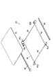
図1に示すように、液晶表示装置は、矩形状を有する光透過型の液晶表示パネル10と、液晶表示パネル10の裏面側に重ねて配置されたほぼ矩形状のバックライトユニット20と、を備えている。液晶表示パネル10の周縁部には、矩形枠状の金属製のベゼル40が被せられ、このベゼルはバックライトユニット20の樹脂製フレーム51に接合されている。従って、液晶表示パネル10は、バックライトユニット20とベゼル40との間に挟持された状態で保持されている。ベゼル40は、例えば0.2mm厚のステンレスによって形成されている。
【0015】
液晶表示パネル10は、矩形状のアレイ基板12および対向基板14、これらの基板間に封入された図示しない液晶層等を備えている。アレイ基板12上には図示しない多数の表示画素、スイッチング素子、配線、およびアナログサンプルホールド回路を含む駆動回路が形成され、矩形状の有効表示領域を有している。また、アレイ基板12には、フレキシブルプリント基板(FPC)15を介してデジタル・アナログ変換回路(DAC)を含む駆動回路基板16が接続されている。この駆動回路基板16は、バックライトユニット20の裏面側に配置されている。
【0016】
図1ないし図3に示すように、バックライトユニット20は、サイドエッジ型の光源ユニットであり、上面を発光面としたアクリル製の矩形状の導光板41と、導光板の下面に貼付あるいは印刷された光散乱シートと、導光板41を支持した樹脂製のフレーム51と、を備えている。
【0017】
また、バックライトユニット20は、導光板41の一側面と対向して設けられた2本の管状光源42と、これらの管状光源からの光源光を導光板41へ効果的に導くために管状光源を覆って配置された断面U字状の反射板43と、を備えている。そして、導光板41、管状光源42、および反射板43は、フレーム51内に嵌合され所定位置に保持されている。
【0018】
各管状光源42の各端には接続ケーブル44が接続され、管状光源から導出している。接続ケーブル44の延出端にはコネクタ38が取りつけられ、このコネクタは図示しないインバータに接続される。
【0019】
図3ないし図6に示すように、2本の管状光源42の両端部には、接続ケーブル44との接続部を固定したゴム製のホルダー45a、45bが設けられている。ホルダー45aは、矩形状の本体46とこの本体から延出した2本の円筒状の延出部48とを一体に有している。
【0020】
本体46には、それぞれ管状光源42の端部が嵌合された2つの嵌合孔50が形成されている。これらの嵌合孔50は、それぞれ対応する延出部48内に連通している。接続ケーブル44の端部は、延出部48内に挿通され、延出部48によって直接的に被覆されている。そして、各接続ケーブル44の端部から延出した芯線44aは、管状光源42の端から導出した端子42aに接続され、この接続部は、本体46の嵌合孔50内に位置し、ホルダー45aによって保護されている。
なお、管状光源42の他端部に設けられたホルダー45bも、上述したホルダー45aと同様に構成されている。また、各ホルダー45a、45bの本体46は、反射板43の端部にそれぞれ嵌合され、2本の管状光源42を反射板43に対して位置決めしている。
【0021】
以上のように構成された液晶表示装置のバックライトユニット20によれば、各管状光源42の端部に嵌合されたゴム製のホルダー45a、45bに円筒状の延出部48を一体に設け、この延出部に接続ケーブル44の端部を直接挿通して延出部で被覆することにより、管状光源42と接続ケーブル44との接続部に作用するストレスを緩和し、接続部の断線や接触不良を防止し信頼性を向上させることができる。
【0022】
そして、このホルダー45a、45bはゴム製で柔軟なため、被覆していても接続ケーブル44を自由に引き回すことができ、更に、従来の被覆よりも丈夫なため、被覆破れによる作業者への感電等も防止することができる。
【0023】
更に、この実施例では、管状光源42と接続ケーブル44との接続部の被覆をゴム製のホルダー45a、45bで兼ねているため、従来用いられていた熱収縮チューブを省略することができ、生産性を向上させると共に、バックライトユニットの製造コストを下げることができる。
【0024】
次に、この発明の他の実施の形態に係るバックライトユニット20について説明する。
図7に示すように、他の実施の形態によれば、バックライトユニット20は2本の管状光源42を備え、これらの管状光源は、導光板41の平行な2側縁に沿ってそれぞれ設けられている。また、バックライトユニット20は、これらの管状光源42からの光源光を導光板41へ効果的に導くために管状光源を覆って配置された断面U字状の2つの反射板43を備えている。
【0025】
各管状光源42の各端には接続ケーブル44が接続され、管状光源から導出している。接続ケーブル44の延出端はコネクタ38に接続され、このコネクタは図示しないインバータに接続される。
【0026】
図7ないし図9に示すように、各管状光源42の両端部には、接続ケーブル44との接続部を固定したゴム製のホルダー45a、45bが設けられている。ホルダー45aは、矩形状の本体46とこの本体から垂直に延出した円筒状の延出部48とを一体に有している。
【0027】
本体46には、管状光源42の端部が嵌合された嵌合孔50が形成され、延出部48内に連通している。延出部48は、その中心軸が嵌合孔50と直交するように設けられている。また、本体46は、延出部48との角部を補強するように形成された突出部60を一体に備えている。
【0028】
接続ケーブル44の端部は、延出部48内に挿通され、延出部48によって直接的に被覆されている。そして、各接続ケーブル44の端部から延出した芯線44aは、管状光源42の端から導出した端子に金属スペーサ62を介して接続され、この接続部は、本体46の嵌合孔50内に位置し、ホルダー45aによって保護されている。また、接続ケーブル44の被覆の端64は、突出部60の上面60aよりも管状光源42側、つまり、本体46側に位置している。
【0029】
本実施の形態において、ホルダー45a、45bの寸法は、突出部60の高さAが1.3mm以上、延出部48の高さBが2.9mm以上、延出部の肉厚が0.4mm以上にそれぞれ形成されている。
なお、管状光源42の他端部に設けられたホルダー45bも、上述したホルダー45aと同様に構成されている。また、各ホルダー45a、45bの本体46は、反射板43の端部にそれぞれ嵌合され、2本の管状光源42を反射板43に対して保持している。
【0030】
以上のように構成された液晶表示装置のバックライトユニット20によれば、各管状光源42の端部に嵌合されたゴム製のホルダー45a、45bに円筒状の延出部48を一体に設け、この延出部に接続ケーブル44の端部を直接挿通して延出部で被覆しているとともに、ホルダー45a、45bの屈曲部となる延出部48と突出部60との境界位置Cは、接続ケーブル44の芯線44aから離間している。そのため、管状光源42と接続ケーブル44との接続部や、接続ケーブルの芯線44aに作用するストレスを緩和し、接続ケーブルの芯線の断線や接続部の接触不良を防止し信頼性を向上させることができる。
【0031】
図9に示すように、接続ケーブル44を矢印D方向に沿って180度屈曲させる試験を実施したところ、従来の構造では、8回の屈曲で管状光源と接続ケーブルの芯線との接続部が切断されてしまったが、本実施の形態に係るホルダーによれば、89回の屈曲で接続ケーブルの芯線が切断するという結果が得られ、従来に比較して約10倍の耐久性を得ることができた。
【0032】
そして、このホルダー45a、45bはゴム製で柔軟なため、被覆していても接続ケーブル44を自由に引き回すことができ、更に、従来の被覆よりも丈夫なため、被覆破れによる作業者への感電等も防止することができる。
【0033】
更に、この実施例では、管状光源42と接続ケーブル44との接続部の被覆をゴム製のホルダー45a、45bで兼ねているため、従来用いられていた熱収縮チューブを省略することができ、生産性の向上させると共に、バックライトユニットの製造コストを下げることもできる。
【0034】
【発明の効果】
以上詳述したように、この発明によれば、接続不良の発生を防止するとともに部品点数の削減を図り、生産性および信頼性が大幅に向上したバックライトユニットを提供することができる。
【図面の簡単な説明】
【図1】この発明の実施の形態に係るバックライトユニットを備えた液晶表示装置の分解斜視図。
【図2】上記バックライトユニットの断面図。
【図3】上記バックライトユニットの分解斜視図。
【図4】上記バックライトユニットにおける管状光源、接続ケーブル、および反射板を示す平面図。
【図5】上記バックライトユニットにおけるゴム製ホルダーを示す斜視図である。
【図6】上記管状光源と接続ケーブルとの接続部、およびホルダーを拡大して示す断面図。
【図7】この発明の他の実施の形態に係るバックライトユニットの分解斜視図。
【図8】上記他の実施の形態におけるバックライトユニットのゴム製ホルダーを示す斜視図である。
【図9】上記管状光源と接続ケーブルとの接続部、およびホルダーを拡大して示す断面図。
【符号の説明】
10…液晶表示パネル
20…バックライトユニット
41…導光板
42…管状光源
43…反射板
44…接続ケーブル
44a…芯線
45a、45b…ホルダー
46…本体
48…延出部
51…フレーム
60…突出部
Claims (2)
- ほぼ矩形状の導光板と、
上記導光板の一側縁に対向して設けられた管状光源と、
上記導光板および管状光源を支持したフレームと、
上記管状光源の両端にそれぞれ接続された接続ケーブルと、
上記管状光源の各端と接続ケーブルとの接続部に装着されたゴム製のホルダーと、を備え、
上記ホルダーは、上記管状光源の端部が嵌合された嵌合孔を有する本体と、上記本体から延出しているとともに上記接続ケーブルの端部が挿通され接続ケーブルの端部を直接被覆した円筒状の延出部と、を一体に備え、
上記接続ケーブルは、上記管状光源に接続された芯線と、芯線を覆った被覆と、を有し、上記被覆の上記管状光源側の端は、上記ホルダーの本体と延出部との境界よりも上記本体側に位置し、
上記各ホルダーの本体は、この本体と上記延出部との境界部に設けられた突出部を一体に備えていることを特徴とするバックライトユニット。 - 上記導光板の対向する2側縁にそれぞれ対向して設けられた2本の上記管状光源を備え、各管状光源の各端に上記ホルダーが嵌合されていることを特徴とする請求項1に記載のバックライトユニット。
Priority Applications (4)
| Application Number | Priority Date | Filing Date | Title |
|---|---|---|---|
| JP36827199A JP4387532B2 (ja) | 1999-12-24 | 1999-12-24 | 平面表示装置のバックライトユニット |
| TW089126025A TWI283780B (en) | 1999-12-24 | 2000-12-06 | Back light unit of plane display apparatus |
| KR1020000078990A KR100360156B1 (ko) | 1999-12-24 | 2000-12-20 | 백라이트 유닛 |
| US09/740,886 US6386722B2 (en) | 1999-12-24 | 2000-12-21 | Backlight unit for use in planar display |
Applications Claiming Priority (1)
| Application Number | Priority Date | Filing Date | Title |
|---|---|---|---|
| JP36827199A JP4387532B2 (ja) | 1999-12-24 | 1999-12-24 | 平面表示装置のバックライトユニット |
Publications (2)
| Publication Number | Publication Date |
|---|---|
| JP2001184919A JP2001184919A (ja) | 2001-07-06 |
| JP4387532B2 true JP4387532B2 (ja) | 2009-12-16 |
Family
ID=18491399
Family Applications (1)
| Application Number | Title | Priority Date | Filing Date |
|---|---|---|---|
| JP36827199A Expired - Lifetime JP4387532B2 (ja) | 1999-12-24 | 1999-12-24 | 平面表示装置のバックライトユニット |
Country Status (4)
| Country | Link |
|---|---|
| US (1) | US6386722B2 (ja) |
| JP (1) | JP4387532B2 (ja) |
| KR (1) | KR100360156B1 (ja) |
| TW (1) | TWI283780B (ja) |
Families Citing this family (29)
| Publication number | Priority date | Publication date | Assignee | Title |
|---|---|---|---|---|
| US6758616B2 (en) * | 2000-01-21 | 2004-07-06 | Fargo Electronics, Inc. | Identification card printer |
| US7004613B2 (en) * | 2000-12-28 | 2006-02-28 | Au Optronics Corp. | Display structure |
| KR100760933B1 (ko) * | 2000-12-30 | 2007-09-21 | 엘지.필립스 엘시디 주식회사 | 액정표시장치용 램프장치 |
| JP3969979B2 (ja) * | 2001-08-29 | 2007-09-05 | 株式会社アドバンスト・ディスプレイ | 平面型表示装置 |
| TW523161U (en) * | 2001-09-20 | 2003-03-01 | Chunghwa Picture Tubes Ltd | Flat panel display used light source of stretch resistance |
| KR100434325B1 (ko) * | 2001-12-26 | 2004-06-04 | 엘지.필립스 엘시디 주식회사 | 액정표시장치의 백라이트용 램프 와이어 설치구조체 |
| KR20030069511A (ko) * | 2002-02-21 | 2003-08-27 | 삼성전자주식회사 | 액정표시장치용 광원장치 |
| US6866397B2 (en) * | 2002-03-01 | 2005-03-15 | Au Optronics Corporation | Leading wire arrangement of a lighting fixture in a back light module |
| US6976781B2 (en) * | 2002-10-25 | 2005-12-20 | Au Optronics Corp. | Frame and bezel structure for backlight unit |
| KR100937408B1 (ko) * | 2002-11-29 | 2010-01-18 | 엘지전자 주식회사 | Lcd 어셈블리의 케이블 인출 구조를 갖는 가전제품 |
| GB0230200D0 (en) * | 2002-12-24 | 2003-02-05 | Esselte Nv | Validation of consumables |
| US6991349B2 (en) * | 2002-12-30 | 2006-01-31 | Chunghwa Picture Tubes, Ltd. | Fixing apparatus for light source conductive wire of backlight module |
| TW587180B (en) * | 2003-02-27 | 2004-05-11 | Quanta Display Inc | Combined frame and back light module |
| TWI294049B (en) * | 2003-11-14 | 2008-03-01 | Sanyo Electric Co | Liquid crystal module |
| MXPA04012681A (es) | 2003-12-26 | 2005-07-01 | Canon Kk | Recipiente para liquido y sistema de suministro de liquido. |
| TWI282885B (en) * | 2004-03-03 | 2007-06-21 | Au Optronics Corp | Backlight assembly |
| CN100414377C (zh) * | 2004-03-26 | 2008-08-27 | 友达光电股份有限公司 | 侧框架的背光组件及其组装方法 |
| WO2005093499A1 (en) * | 2004-03-26 | 2005-10-06 | Quanta Display Inc. | Backlight assembly with side frame and assembly method thereof |
| JP4459109B2 (ja) * | 2005-05-13 | 2010-04-28 | 東芝モバイルディスプレイ株式会社 | 面光源装置、及びこの面光源装置を備えた液晶表示装置 |
| US20080037287A1 (en) * | 2006-08-14 | 2008-02-14 | Robert Michael Krohn | Backlight panel and manufacturing method thereof |
| KR20070020642A (ko) * | 2005-08-16 | 2007-02-22 | 삼성전자주식회사 | 클립 램프, 백라이트 어셈블리 및 이를 갖는 표시장치 |
| TWI345103B (en) * | 2005-09-30 | 2011-07-11 | Chimei Innolux Corp | Back light module and liquid crystal display |
| US7367707B2 (en) * | 2005-12-16 | 2008-05-06 | Chunghwa Picture Tubes, Ltd. | Backlight module |
| TWI339298B (en) * | 2006-12-29 | 2011-03-21 | Chimei Innolux Corp | Backlight module |
| JP4626657B2 (ja) * | 2008-02-12 | 2011-02-09 | 日亜化学工業株式会社 | バックライトユニット |
| TWI420435B (zh) * | 2008-12-12 | 2013-12-21 | Innolux Corp | 平面顯示裝置及其框體單元 |
| KR101952774B1 (ko) * | 2012-05-17 | 2019-02-27 | 엘지디스플레이 주식회사 | 백 라이트 유닛 및 이를 포함하는 액정 표시 장치 |
| JP5979363B2 (ja) * | 2012-08-20 | 2016-08-24 | パナソニックIpマネジメント株式会社 | 照明器具 |
| JP7200663B2 (ja) * | 2018-12-26 | 2023-01-10 | トヨタ紡織株式会社 | 車内照明装置 |
Family Cites Families (2)
| Publication number | Priority date | Publication date | Assignee | Title |
|---|---|---|---|---|
| WO1994001795A1 (fr) * | 1992-07-13 | 1994-01-20 | Seiko Epson Corporation | Dispositif d'eclairage de surface et affichage a cristaux liquides |
| JPH07181484A (ja) * | 1993-11-05 | 1995-07-21 | Internatl Business Mach Corp <Ibm> | 液晶ディスプレイ用バックライト及び液晶ディスプレイ |
-
1999
- 1999-12-24 JP JP36827199A patent/JP4387532B2/ja not_active Expired - Lifetime
-
2000
- 2000-12-06 TW TW089126025A patent/TWI283780B/zh not_active IP Right Cessation
- 2000-12-20 KR KR1020000078990A patent/KR100360156B1/ko not_active Expired - Fee Related
- 2000-12-21 US US09/740,886 patent/US6386722B2/en not_active Expired - Lifetime
Also Published As
| Publication number | Publication date |
|---|---|
| US20010006459A1 (en) | 2001-07-05 |
| US6386722B2 (en) | 2002-05-14 |
| KR100360156B1 (ko) | 2002-11-07 |
| KR20010062536A (ko) | 2001-07-07 |
| TWI283780B (en) | 2007-07-11 |
| JP2001184919A (ja) | 2001-07-06 |
Similar Documents
| Publication | Publication Date | Title |
|---|---|---|
| KR100360156B1 (ko) | 백라이트 유닛 | |
| US7764335B2 (en) | Liquid crystal module | |
| KR960016635B1 (ko) | 액정 표시 장치 | |
| JP5283255B2 (ja) | 液晶表示装置 | |
| US9823509B2 (en) | Display device | |
| TW201506498A (zh) | 彎曲顯示裝置 | |
| JPWO2010021200A1 (ja) | 電子パッケージ、表示装置、および電子機器 | |
| US6419369B1 (en) | Sheet-like source light device and liquid crystal display device using the same | |
| EP4207960B1 (en) | Whole unit structure and display device | |
| JP2001091947A (ja) | 液晶表示装置 | |
| US8174644B2 (en) | Liquid crystal module | |
| US20060092661A1 (en) | Surface light source device | |
| KR101398123B1 (ko) | 램프 소켓 및 이를 포함하는 표시 장치, 램프 조립 방법 | |
| JP2001051619A (ja) | 平面表示装置 | |
| JP5621647B2 (ja) | 液晶表示装置 | |
| JP2001174789A (ja) | 液晶表示装置 | |
| KR100966432B1 (ko) | 인쇄회로 기판의 접지 방식을 개선한 액정표시장치 | |
| KR20070047962A (ko) | 액정표시장치 | |
| CN222319250U (zh) | 一种薄型化背光模组 | |
| CN114859609B (zh) | 柔性电路板、显示装置以及显示装置的制备方法 | |
| JP3322592B2 (ja) | 液晶表示装置およびその製造方法 | |
| JPH11271769A (ja) | バックライトユニットおよびこれを備えた液晶表示装置 | |
| KR20090073881A (ko) | 액정표시장치 | |
| KR100796491B1 (ko) | 커넥터 고정부를 구비한 액정모듈 | |
| JPH08664Y2 (ja) | 液晶表示装置 |
Legal Events
| Date | Code | Title | Description |
|---|---|---|---|
| A621 | Written request for application examination |
Free format text: JAPANESE INTERMEDIATE CODE: A621 Effective date: 20061012 |
|
| A711 | Notification of change in applicant |
Free format text: JAPANESE INTERMEDIATE CODE: A711 Effective date: 20070514 |
|
| A977 | Report on retrieval |
Free format text: JAPANESE INTERMEDIATE CODE: A971007 Effective date: 20081114 |
|
| A131 | Notification of reasons for refusal |
Free format text: JAPANESE INTERMEDIATE CODE: A131 Effective date: 20090113 |
|
| A521 | Written amendment |
Free format text: JAPANESE INTERMEDIATE CODE: A523 Effective date: 20090304 |
|
| TRDD | Decision of grant or rejection written | ||
| A01 | Written decision to grant a patent or to grant a registration (utility model) |
Free format text: JAPANESE INTERMEDIATE CODE: A01 Effective date: 20090908 |
|
| A01 | Written decision to grant a patent or to grant a registration (utility model) |
Free format text: JAPANESE INTERMEDIATE CODE: A01 |
|
| A61 | First payment of annual fees (during grant procedure) |
Free format text: JAPANESE INTERMEDIATE CODE: A61 Effective date: 20091001 |
|
| R150 | Certificate of patent or registration of utility model |
Free format text: JAPANESE INTERMEDIATE CODE: R150 |
|
| FPAY | Renewal fee payment (event date is renewal date of database) |
Free format text: PAYMENT UNTIL: 20121009 Year of fee payment: 3 |
|
| S531 | Written request for registration of change of domicile |
Free format text: JAPANESE INTERMEDIATE CODE: R313531 |
|
| FPAY | Renewal fee payment (event date is renewal date of database) |
Free format text: PAYMENT UNTIL: 20121009 Year of fee payment: 3 |
|
| R350 | Written notification of registration of transfer |
Free format text: JAPANESE INTERMEDIATE CODE: R350 |