JP4436865B2 - コンバータ向け制御回路 - Google Patents
コンバータ向け制御回路 Download PDFInfo
- Publication number
- JP4436865B2 JP4436865B2 JP2007500037A JP2007500037A JP4436865B2 JP 4436865 B2 JP4436865 B2 JP 4436865B2 JP 2007500037 A JP2007500037 A JP 2007500037A JP 2007500037 A JP2007500037 A JP 2007500037A JP 4436865 B2 JP4436865 B2 JP 4436865B2
- Authority
- JP
- Japan
- Prior art keywords
- threshold
- threshold element
- switching transistor
- output signal
- mos1
- Prior art date
- Legal status (The legal status is an assumption and is not a legal conclusion. Google has not performed a legal analysis and makes no representation as to the accuracy of the status listed.)
- Expired - Fee Related
Links
Images
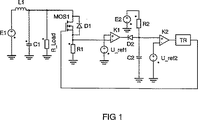
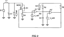
Classifications
-
- H—ELECTRICITY
- H05—ELECTRIC TECHNIQUES NOT OTHERWISE PROVIDED FOR
- H05B—ELECTRIC HEATING; ELECTRIC LIGHT SOURCES NOT OTHERWISE PROVIDED FOR; CIRCUIT ARRANGEMENTS FOR ELECTRIC LIGHT SOURCES, IN GENERAL
- H05B41/00—Circuit arrangements or apparatus for igniting or operating discharge lamps
- H05B41/14—Circuit arrangements
- H05B41/26—Circuit arrangements in which the lamp is fed by power derived from DC by means of a converter, e.g. by high-voltage DC
- H05B41/28—Circuit arrangements in which the lamp is fed by power derived from DC by means of a converter, e.g. by high-voltage DC using static converters
- H05B41/2806—Circuit arrangements in which the lamp is fed by power derived from DC by means of a converter, e.g. by high-voltage DC using static converters with semiconductor devices and specially adapted for lamps without electrodes in the vessel, e.g. surface discharge lamps, electrodeless discharge lamps
-
- H—ELECTRICITY
- H05—ELECTRIC TECHNIQUES NOT OTHERWISE PROVIDED FOR
- H05B—ELECTRIC HEATING; ELECTRIC LIGHT SOURCES NOT OTHERWISE PROVIDED FOR; CIRCUIT ARRANGEMENTS FOR ELECTRIC LIGHT SOURCES, IN GENERAL
- H05B41/00—Circuit arrangements or apparatus for igniting or operating discharge lamps
- H05B41/14—Circuit arrangements
- H05B41/24—Circuit arrangements in which the lamp is fed by high frequency AC, or with separate oscillator frequency
-
- H—ELECTRICITY
- H02—GENERATION; CONVERSION OR DISTRIBUTION OF ELECTRIC POWER
- H02M—APPARATUS FOR CONVERSION BETWEEN AC AND AC, BETWEEN AC AND DC, OR BETWEEN DC AND DC, AND FOR USE WITH MAINS OR SIMILAR POWER SUPPLY SYSTEMS; CONVERSION OF DC OR AC INPUT POWER INTO SURGE OUTPUT POWER; CONTROL OR REGULATION THEREOF
- H02M3/00—Conversion of DC power input into DC power output
- H02M3/02—Conversion of DC power input into DC power output without intermediate conversion into AC
- H02M3/04—Conversion of DC power input into DC power output without intermediate conversion into AC by static converters
- H02M3/10—Conversion of DC power input into DC power output without intermediate conversion into AC by static converters using discharge tubes with control electrode or semiconductor devices with control electrode
- H02M3/145—Conversion of DC power input into DC power output without intermediate conversion into AC by static converters using discharge tubes with control electrode or semiconductor devices with control electrode using devices of a triode or transistor type requiring continuous application of a control signal
- H02M3/155—Conversion of DC power input into DC power output without intermediate conversion into AC by static converters using discharge tubes with control electrode or semiconductor devices with control electrode using devices of a triode or transistor type requiring continuous application of a control signal using semiconductor devices only
- H02M3/156—Conversion of DC power input into DC power output without intermediate conversion into AC by static converters using discharge tubes with control electrode or semiconductor devices with control electrode using devices of a triode or transistor type requiring continuous application of a control signal using semiconductor devices only with automatic control of output voltage or current, e.g. switching regulators
-
- H—ELECTRICITY
- H05—ELECTRIC TECHNIQUES NOT OTHERWISE PROVIDED FOR
- H05B—ELECTRIC HEATING; ELECTRIC LIGHT SOURCES NOT OTHERWISE PROVIDED FOR; CIRCUIT ARRANGEMENTS FOR ELECTRIC LIGHT SOURCES, IN GENERAL
- H05B41/00—Circuit arrangements or apparatus for igniting or operating discharge lamps
- H05B41/14—Circuit arrangements
-
- H—ELECTRICITY
- H05—ELECTRIC TECHNIQUES NOT OTHERWISE PROVIDED FOR
- H05B—ELECTRIC HEATING; ELECTRIC LIGHT SOURCES NOT OTHERWISE PROVIDED FOR; CIRCUIT ARRANGEMENTS FOR ELECTRIC LIGHT SOURCES, IN GENERAL
- H05B41/00—Circuit arrangements or apparatus for igniting or operating discharge lamps
- H05B41/14—Circuit arrangements
- H05B41/26—Circuit arrangements in which the lamp is fed by power derived from DC by means of a converter, e.g. by high-voltage DC
- H05B41/28—Circuit arrangements in which the lamp is fed by power derived from DC by means of a converter, e.g. by high-voltage DC using static converters
- H05B41/282—Circuit arrangements in which the lamp is fed by power derived from DC by means of a converter, e.g. by high-voltage DC using static converters with semiconductor devices
-
- Y—GENERAL TAGGING OF NEW TECHNOLOGICAL DEVELOPMENTS; GENERAL TAGGING OF CROSS-SECTIONAL TECHNOLOGIES SPANNING OVER SEVERAL SECTIONS OF THE IPC; TECHNICAL SUBJECTS COVERED BY FORMER USPC CROSS-REFERENCE ART COLLECTIONS [XRACs] AND DIGESTS
- Y02—TECHNOLOGIES OR APPLICATIONS FOR MITIGATION OR ADAPTATION AGAINST CLIMATE CHANGE
- Y02B—CLIMATE CHANGE MITIGATION TECHNOLOGIES RELATED TO BUILDINGS, e.g. HOUSING, HOUSE APPLIANCES OR RELATED END-USER APPLICATIONS
- Y02B20/00—Energy efficient lighting technologies, e.g. halogen lamps or gas discharge lamps
Landscapes
- Engineering & Computer Science (AREA)
- Power Engineering (AREA)
- Dc-Dc Converters (AREA)
- Electronic Switches (AREA)
- Circuit Arrangements For Discharge Lamps (AREA)
- Control Of Motors That Do Not Use Commutators (AREA)
- Analogue/Digital Conversion (AREA)
Applications Claiming Priority (2)
| Application Number | Priority Date | Filing Date | Title |
|---|---|---|---|
| DE102004008908A DE102004008908A1 (de) | 2004-02-24 | 2004-02-24 | Ansteuerschaltung für Wandler |
| PCT/DE2005/000155 WO2005084084A1 (de) | 2004-02-24 | 2005-02-01 | Ansteuerschaltung für wandler |
Publications (2)
| Publication Number | Publication Date |
|---|---|
| JP2007535887A JP2007535887A (ja) | 2007-12-06 |
| JP4436865B2 true JP4436865B2 (ja) | 2010-03-24 |
Family
ID=34833003
Family Applications (1)
| Application Number | Title | Priority Date | Filing Date |
|---|---|---|---|
| JP2007500037A Expired - Fee Related JP4436865B2 (ja) | 2004-02-24 | 2005-02-01 | コンバータ向け制御回路 |
Country Status (10)
| Country | Link |
|---|---|
| US (1) | US7564673B2 (de) |
| EP (1) | EP1738618B1 (de) |
| JP (1) | JP4436865B2 (de) |
| KR (1) | KR101109820B1 (de) |
| CN (1) | CN1922935B (de) |
| AT (1) | ATE420544T1 (de) |
| CA (1) | CA2556182A1 (de) |
| DE (2) | DE102004008908A1 (de) |
| TW (1) | TWI345879B (de) |
| WO (1) | WO2005084084A1 (de) |
Families Citing this family (3)
| Publication number | Priority date | Publication date | Assignee | Title |
|---|---|---|---|---|
| DE202006004296U1 (de) | 2006-03-17 | 2006-06-14 | Patent-Treuhand-Gesellschaft für elektrische Glühlampen mbH | Ausschaltzeitregelung |
| US20140312969A1 (en) | 2011-10-14 | 2014-10-23 | Indice Pty Ltd | Power control |
| AR117844A1 (es) * | 2019-01-22 | 2021-09-01 | Merck Patent Gmbh | Derivados de tiazolopiridina como antagonistas del receptor de adenosina |
Family Cites Families (9)
| Publication number | Priority date | Publication date | Assignee | Title |
|---|---|---|---|---|
| US4714978A (en) * | 1986-04-17 | 1987-12-22 | Xerox Corporation | Power supply for a.c. corotrons |
| JPH01223789A (ja) | 1988-03-02 | 1989-09-06 | Mitsubishi Electric Corp | 固体レーザ励起用ランプの電源装置 |
| US5097182A (en) | 1990-10-19 | 1992-03-17 | Kelly Allen D | Power supply for a gas discharge lamp |
| FR2721475B1 (fr) | 1994-06-15 | 1996-07-19 | Sgs Thomson Microelectronics | Circuit de commande de commutation et dispositif de commande pour lampe fluorescente à basse pression. |
| JP3547837B2 (ja) | 1995-03-31 | 2004-07-28 | ミネベア株式会社 | インバ−タ装置 |
| JPH10304555A (ja) | 1997-04-18 | 1998-11-13 | Oki Electric Ind Co Ltd | Dc/dcコンバータの制御回路 |
| EP0936845B1 (de) | 1998-02-10 | 2002-09-18 | STMicroelectronics S.A. | Gerät und Verfahren zum Zünden und Betreiben einer Leuchtstofflampe |
| JP3282594B2 (ja) | 1998-10-05 | 2002-05-13 | 株式会社村田製作所 | 圧電トランスインバータ |
| JP3061049B1 (ja) * | 1999-04-09 | 2000-07-10 | 株式会社村田製作所 | 圧電トランスインバ―タ |
-
2004
- 2004-02-24 DE DE102004008908A patent/DE102004008908A1/de not_active Withdrawn
-
2005
- 2005-02-01 AT AT05706730T patent/ATE420544T1/de not_active IP Right Cessation
- 2005-02-01 JP JP2007500037A patent/JP4436865B2/ja not_active Expired - Fee Related
- 2005-02-01 KR KR1020067017695A patent/KR101109820B1/ko not_active Expired - Fee Related
- 2005-02-01 CN CN2005800058088A patent/CN1922935B/zh not_active Expired - Fee Related
- 2005-02-01 DE DE200550006426 patent/DE502005006426D1/de not_active Expired - Lifetime
- 2005-02-01 WO PCT/DE2005/000155 patent/WO2005084084A1/de not_active Ceased
- 2005-02-01 US US10/589,671 patent/US7564673B2/en not_active Expired - Fee Related
- 2005-02-01 EP EP05706730A patent/EP1738618B1/de not_active Expired - Lifetime
- 2005-02-01 CA CA 2556182 patent/CA2556182A1/en not_active Abandoned
- 2005-02-21 TW TW94105025A patent/TWI345879B/zh not_active IP Right Cessation
Also Published As
| Publication number | Publication date |
|---|---|
| WO2005084084A1 (de) | 2005-09-09 |
| KR20060130194A (ko) | 2006-12-18 |
| EP1738618A1 (de) | 2007-01-03 |
| DE502005006426D1 (de) | 2009-02-26 |
| TW200531440A (en) | 2005-09-16 |
| DE102004008908A1 (de) | 2005-09-08 |
| TWI345879B (en) | 2011-07-21 |
| CN1922935A (zh) | 2007-02-28 |
| US20080151586A1 (en) | 2008-06-26 |
| US7564673B2 (en) | 2009-07-21 |
| ATE420544T1 (de) | 2009-01-15 |
| CA2556182A1 (en) | 2005-09-09 |
| KR101109820B1 (ko) | 2012-02-13 |
| CN1922935B (zh) | 2012-06-20 |
| JP2007535887A (ja) | 2007-12-06 |
| EP1738618B1 (de) | 2009-01-07 |
Similar Documents
| Publication | Publication Date | Title |
|---|---|---|
| US5500792A (en) | Zero-voltage switching type electronic ballast for fluorescent lamp | |
| US11539294B2 (en) | Multi-level power converter with light load flying capacitor voltage regulation | |
| US20050212497A1 (en) | DC-DC converter and control method thereof | |
| US8294494B2 (en) | Triangular-wave generating circuit synchronized with an external circuit | |
| US6815908B2 (en) | Dimmable self-oscillating electronic ballast for fluorescent lamp | |
| JP2005005112A (ja) | Led駆動回路 | |
| CN101960924B (zh) | 可调光瞬时启动镇流器 | |
| AU2003205038B2 (en) | Drive for a half-bridge inverter | |
| US5065072A (en) | Power supply circuit for an arc lamp, in particular for a motor vehicle headlight | |
| JP2933077B1 (ja) | 放電灯点灯装置 | |
| JP2001006886A (ja) | 放電灯点灯回路 | |
| US20070285130A1 (en) | Floating driving circuit | |
| RU2420858C2 (ru) | Коммутационная схема и способ управления потребителем электроэнергии | |
| JP2007535887A (ja) | コンバータ向け制御回路 | |
| CN101060743B (zh) | 谐振逆变器 | |
| CN112467976B (zh) | 开关变换器及其控制电路和控制方法 | |
| US7095184B2 (en) | Electronic ballast for a lamp to be operated using iterative voltage pulses | |
| IT201800002255A1 (it) | Circuito a commutazione, dispositivo e procedimento corrispondenti | |
| JP4193798B2 (ja) | 放電管点灯装置 | |
| JP2024511568A5 (de) | ||
| JPH04351898A (ja) | 放電ランプ作動用回路装置 | |
| HUP0204233A2 (en) | Electronic ballast circuit and method for operating a high intensity discharge lamp | |
| JP4012646B2 (ja) | スイッチング回路 | |
| CN112996185B (zh) | 固态光源驱动电路及应用其的投影机 | |
| JP2002272128A (ja) | 半ブリッジ変換器用シャットダウン回路 |
Legal Events
| Date | Code | Title | Description |
|---|---|---|---|
| A131 | Notification of reasons for refusal |
Free format text: JAPANESE INTERMEDIATE CODE: A131 Effective date: 20090213 |
|
| A601 | Written request for extension of time |
Free format text: JAPANESE INTERMEDIATE CODE: A601 Effective date: 20090512 |
|
| A602 | Written permission of extension of time |
Free format text: JAPANESE INTERMEDIATE CODE: A602 Effective date: 20090519 |
|
| A521 | Request for written amendment filed |
Free format text: JAPANESE INTERMEDIATE CODE: A523 Effective date: 20090811 |
|
| TRDD | Decision of grant or rejection written | ||
| A01 | Written decision to grant a patent or to grant a registration (utility model) |
Free format text: JAPANESE INTERMEDIATE CODE: A01 Effective date: 20091127 |
|
| A01 | Written decision to grant a patent or to grant a registration (utility model) |
Free format text: JAPANESE INTERMEDIATE CODE: A01 |
|
| A61 | First payment of annual fees (during grant procedure) |
Free format text: JAPANESE INTERMEDIATE CODE: A61 Effective date: 20091228 |
|
| R150 | Certificate of patent or registration of utility model |
Ref document number: 4436865 Country of ref document: JP Free format text: JAPANESE INTERMEDIATE CODE: R150 Free format text: JAPANESE INTERMEDIATE CODE: R150 |
|
| FPAY | Renewal fee payment (event date is renewal date of database) |
Free format text: PAYMENT UNTIL: 20130108 Year of fee payment: 3 |
|
| R250 | Receipt of annual fees |
Free format text: JAPANESE INTERMEDIATE CODE: R250 |
|
| R250 | Receipt of annual fees |
Free format text: JAPANESE INTERMEDIATE CODE: R250 |
|
| R250 | Receipt of annual fees |
Free format text: JAPANESE INTERMEDIATE CODE: R250 |
|
| R250 | Receipt of annual fees |
Free format text: JAPANESE INTERMEDIATE CODE: R250 |
|
| R250 | Receipt of annual fees |
Free format text: JAPANESE INTERMEDIATE CODE: R250 |
|
| R250 | Receipt of annual fees |
Free format text: JAPANESE INTERMEDIATE CODE: R250 |
|
| LAPS | Cancellation because of no payment of annual fees |