JP4446246B2 - Work suction device - Google Patents
Work suction device Download PDFInfo
- Publication number
- JP4446246B2 JP4446246B2 JP2004233389A JP2004233389A JP4446246B2 JP 4446246 B2 JP4446246 B2 JP 4446246B2 JP 2004233389 A JP2004233389 A JP 2004233389A JP 2004233389 A JP2004233389 A JP 2004233389A JP 4446246 B2 JP4446246 B2 JP 4446246B2
- Authority
- JP
- Japan
- Prior art keywords
- valve
- drain tank
- tank
- drain
- vacuum
- Prior art date
- Legal status (The legal status is an assumption and is not a legal conclusion. Google has not performed a legal analysis and makes no representation as to the accuracy of the status listed.)
- Expired - Fee Related
Links
Images




Landscapes
- Jigs For Machine Tools (AREA)
- Constituent Portions Of Griding Lathes, Driving, Sensing And Control (AREA)
- Finish Polishing, Edge Sharpening, And Grinding By Specific Grinding Devices (AREA)
- Mechanical Treatment Of Semiconductor (AREA)
Description
本発明はワーク吸着装置に係り、特に化学的機械研磨法(CMP)により研磨加工される半導体ウェーハ等のワークを、研磨装置において吸着保持するワーク吸着装置に関する。 The present invention relates to a workpiece suction device, and more particularly, to a workpiece suction device that holds a workpiece such as a semiconductor wafer polished by chemical mechanical polishing (CMP) by suction.
半導体技術の発展により、デザインルールの微細化、多層配線化が進行してきている。このため、従来のように、パターンを形成した層の上にそのまま次の層のパターンを形成しようとした場合、前の層の凹凸のために次の層では良好なパターンを形成することが困難であった。そこで、パターンを形成した層の表面を平坦化し、その後で次の層のパターンを形成することが行われている。この場合の平坦化装置として、CMP法によるウェーハの研磨装置が用いられている。 With the development of semiconductor technology, miniaturization of design rules and multilayer wiring are progressing. For this reason, when it is going to form the pattern of the next layer as it is on the layer in which the pattern was formed like before, it is difficult to form a good pattern in the next layer because of the unevenness of the previous layer. Met. Therefore, the surface of the layer on which the pattern is formed is flattened, and then the pattern of the next layer is formed. As a planarization apparatus in this case, a wafer polishing apparatus using a CMP method is used.
従来、この種の研磨装置は、各々独立した回転機構により回転される研磨定盤とウェーハ保持ヘッドとから構成され、半導体ウェーハをウェーハ保持ヘッドに保持させた状態で、研磨定盤に貼られた研磨布に押し付けるとともに、研磨材であるスラリを供給することにより、半導体ウェーハの表面を化学的に腐食させながら機械的に研磨する。 Conventionally, this type of polishing apparatus is composed of a polishing surface plate and a wafer holding head each rotated by an independent rotation mechanism, and is attached to the polishing surface plate with the semiconductor wafer held by the wafer holding head. By pressing against the polishing cloth and supplying a slurry as an abrasive, the surface of the semiconductor wafer is mechanically polished while being chemically corroded.
このような研磨装置では、ウェーハの搬送機構を簡易化するために、ウェーハ搬送用のヘッドとしてウェーハ保持ヘッドが兼用されている。また、ウェーハ保持ヘッドは、ウェーハを吸着する際に、そのウェーハに付着している水滴(加工液、洗浄液等の液体)をも吸引するため、吸引して吸い込んだ水滴を減圧ポンプの前段にて貯留するドレインタンクを備えた吸引装置が知られている(例えば、特許文献1)。ドレインタンクに溜まった排液は、ドレインタンクの排水用バルブを開放してドレインタンクを大気開放した後、加圧したエアをドレインタンクに供給することにより、ドレインタンクから強制的に排水される。 In such a polishing apparatus, in order to simplify the wafer transfer mechanism, a wafer holding head is also used as a wafer transfer head. The wafer holding head also sucks water droplets (processing liquid, cleaning liquid, etc.) adhering to the wafer when adsorbing the wafer. A suction device having a drain tank for storing is known (for example, Patent Document 1). The drainage liquid accumulated in the drain tank is forcibly drained from the drain tank by opening the drain tank drain valve to open the drain tank to the atmosphere and then supplying pressurized air to the drain tank.
なお、ワークを吸着保持する吸着保持部は、研磨装置に適用されたウェーハ保持ヘッドに限定されるものではなく、加工対象物のワークを減圧吸着する吸着保持部全般を対象としている。
しかしながら、特許文献1のワーク吸着装置は、ドレインタンクに溜まった排液を排水する場合、ドレインタンクは真空に維持されているので、まず、ドレインタンクを大気開放する必要があった。このため、研磨の自動運転中では、すなわち、ウェーハ保持ヘッドがウェーハを吸着保持している状態下では、ドレインタンク内の排液を排出することができず、排水する場合には、運転を停止させる必要があるため、ウェーハの研磨効率が低下するという問題があり、また、装置の運転を停止させるタイミングを計ることも非常に困難であった。更に、排液排水後に半導体ウェーハをウェーハ保持ヘッドによって再度吸着保持する際には、ドレインタンクを再び真空状態に減圧しなければならず、この間、研磨加工が中断するので、これもまた研磨加工能率が低下する原因になっていた。更にまた、ドレインタンクの排液排水は自動化されていないので、排液排水は、オペレータによる目視検査等によって排水時期が判断されていた。 However, when the drainage liquid collected in the drain tank is drained, the work suction device of Patent Document 1 needs to open the drain tank to the atmosphere first because the drain tank is maintained in vacuum. For this reason, during the automatic polishing operation, that is, when the wafer holding head is holding the wafer by suction, the drainage liquid in the drain tank cannot be discharged, and the operation is stopped when draining. Therefore, there is a problem that the polishing efficiency of the wafer is lowered, and it is very difficult to measure the timing for stopping the operation of the apparatus. Furthermore, when the semiconductor wafer is again adsorbed and held by the wafer holding head after draining the drainage, the drain tank must be evacuated again, and the polishing process is interrupted during this time, which is also the polishing process efficiency. Was the cause of the decline. Furthermore, since the drainage drainage of the drain tank is not automated, the drainage timing of the drainage drainage was determined by visual inspection or the like by an operator.
本発明はこのような事情に鑑みてなされたもので、ワークの吸着搬送中においてもドレインタンクに溜まった排液を排水することができるとともに、その排液排水処理を自動化することができるワーク吸着装置を提供することを目的とする。 The present invention has been made in view of such circumstances, and it is possible to drain the waste liquid accumulated in the drain tank even during the suction conveyance of the workpiece, and the workpiece suction capable of automating the drainage drainage treatment. An object is to provide an apparatus.
請求項1に記載の発明は、前記目的を達成するために、減圧ラインを介して接続されるとともに加工対象物のワークを減圧吸着する減圧吸着機構と、前記減圧ラインに取り付けられることにより真空に保持され、前記減圧吸着機構によって吸い込まれた排液が減圧ラインを介して捕集される第1のドレインタンクと、前記第1のドレインタンクに連通された第2のドレインタンクと、前記第1のドレインタンクに溜まった前記排液を前記第2のドレインタンクに排出するための第1のバルブと、前記第2のドレインタンクを大気開放させる第2のバルブと、前記第2のドレインタンクに溜まった排液を外部に排水するための第3のバルブと、前記減圧ラインに接続されて真空に保持されるとともに、前記第2のドレインタンクに連結ラインを介して接続された緩衝タンクと、前記連結ラインに設けられるとともに、開放されることにより前記緩衝タンクの真空によって第2のドレインタンクを減圧させる第4のバルブと、を備えたことを特徴としている。 In order to achieve the above-mentioned object, the invention according to claim 1 is connected to the decompression line and vacuum-suction mechanism for vacuum-sucking the workpiece to be processed, and is attached to the decompression line so that the vacuum is achieved. A first drain tank in which the drained liquid that is held and sucked in by the reduced pressure adsorption mechanism is collected via a reduced pressure line, a second drain tank that communicates with the first drain tank, and the first A first valve for discharging the drainage liquid accumulated in the drain tank to the second drain tank, a second valve for opening the second drain tank to the atmosphere, and the second drain tank. A third valve for draining the accumulated drainage liquid to the outside, and connected to the decompression line and held in vacuum, and a connection line is connected to the second drain tank. A buffer tank connected to, together provided in the connecting line, is characterized in that and a fourth valve for decompressing the second drain tank by a vacuum of the buffer tank by being opened .
請求項1に記載の発明は、第1のドレインタンク及び第2のドレインタンクと、緩衝タンクとを備え、これらのタンクに取り付けられている第1乃至第2のバルブの開閉タイミングを制御することにより、ワークの吸着搬送中における排液排水と、その排液排水処理を自動化することを可能としたものである。 The invention according to claim 1 includes a first drain tank, a second drain tank, and a buffer tank, and controls opening and closing timings of first to second valves attached to these tanks. Accordingly, it is possible to automate the drainage drainage during the suction conveyance of the workpiece and the drainage drainage treatment.
請求項2に記載の発明は、前記緩衝タンクは、前記第2のドレインタンクの容積よりも大容積であることを特徴としている。 The invention according to claim 2 is characterized in that the buffer tank has a volume larger than that of the second drain tank.
請求項3に記載の発明は、前記第2のドレインタンクは、前記第1のドレインタンクの真下にあることを特徴としている。 The invention according to claim 3 is characterized in that the second drain tank is directly below the first drain tank .
請求項4に記載の発明は、前記第1のドレインタンクに捕集された排液の水位を検出する水位検出手段を設けるとともに、前記水位手段からの水位情報に基づいて、前記第1のバルブ、前記第2のバルブ、前記第3のバルブ、及び前記第4のバルブの開閉動作をそれぞれ制御する制御部を備えたことを特徴としている。 The invention according to claim 4 is provided with a water level detecting means for detecting the water level of the drained liquid collected in the first drain tank, and based on the water level information from the water level means, the first valve And a control unit for controlling the opening and closing operations of the second valve, the third valve, and the fourth valve, respectively.
具体的には、請求項6に記載の如く、制御部は、ワークの吸着搬送中において真空状態の第1のドレインタンクに取り付けた水位検出手段から排液排水情報が出力されると、まず、第1のバルブを開放させて第1のドレインタンクに溜められた排液を、同じく真空状態の第2のドレインタンクに排出する。次に、制御部は、第1のバルブを閉鎖して第1のドレインタンクと第2のドレインタンクとを遮断する。次いで、制御部は、第2のバルブを開放させて第2のドレインタンクのみを大気開放させるとともに、第3のバルブを開放させて第2のドレインタンクに溜められた排液を外部に排水する。そして、制御部は、第3のバルブを閉鎖させて第2のドレインタンクを密閉し、第4のバルブを開放させることにより第2のドレインタンクを、緩衝タンクの真空により減圧させる。これにより、排液が実際に溜まる第1のドレインタンクは、常時真空状態下にあるので、ワークの吸着搬送中における排液排水が可能になり、また、上述の如く制御部によって第1乃至第4のバルブの開閉を制御することによって、排液排水処理を自動化することが可能になる。 Specifically, as described in claim 6, when the drainage drainage information is output from the water level detection means attached to the first drain tank in the vacuum state during the suction conveyance of the workpiece, The first valve is opened, and the drainage liquid stored in the first drain tank is discharged to the second drain tank that is also in a vacuum state. Next, the control unit closes the first valve to shut off the first drain tank and the second drain tank. Next, the control unit opens the second valve to open only the second drain tank to the atmosphere, and opens the third valve to drain the waste liquid stored in the second drain tank to the outside. . Then, the control unit closes the third valve to seal the second drain tank, and opens the fourth valve to depressurize the second drain tank by the vacuum of the buffer tank. As a result, the first drain tank in which the drainage is actually accumulated is always in a vacuum state, so that the drainage drainage can be performed while the workpiece is being sucked and transported. By controlling the opening and closing of the valve 4, it becomes possible to automate the drainage and drainage treatment.
請求項5に記載の発明は、前記第1のバルブ、前記第2のバルブ、前記第3のバルブ、及び前記第4のバルブの開閉動作をそれぞれ制御する制御部を備えたことを特徴としている。 According to a fifth aspect of the present invention, there is provided a control unit that controls the opening / closing operations of the first valve, the second valve, the third valve, and the fourth valve. .
具体的には、請求項7に記載の如く、制御部は、所定の時間が経過すると、まず、第1のバルブを開放させて第1のドレインタンクに溜められた排液を、同じく真空状態の第2のドレインタンクに排出する。次に、制御部は、第1のバルブを閉鎖して第1のドレインタンクと第2のドレインタンクとを遮断する。次いで、制御部は、第2のバルブを開放させて第2のドレインタンクのみを大気開放させるとともに、第3のバルブを開放させて第2のドレインタンクに溜められた排液を外部に排水する。そして、制御部は、第3のバルブを閉鎖させて第2のドレインタンクを密閉し、第4のバルブを開放させることにより第2のドレインタンクを、緩衝タンクの真空により減圧させる。これにより、排液が実際に溜まる第1のドレインタンクは、常時真空状態下にあるので、ワークの吸着搬送中における排液排水が可能になり、また、上述の如く制御部によって第1乃至第4のバルブの開閉を制御することによって、排液排水処理を自動化することが可能になる。 Specifically, as described in claim 7, when a predetermined time has elapsed, the control unit first opens the first valve and discharges the liquid stored in the first drain tank in the same vacuum state. To the second drain tank. Next, the control unit closes the first valve to shut off the first drain tank and the second drain tank. Next, the control unit opens the second valve to open only the second drain tank to the atmosphere, and opens the third valve to drain the waste liquid stored in the second drain tank to the outside. . Then, the control unit closes the third valve to seal the second drain tank, and opens the fourth valve to depressurize the second drain tank by the vacuum of the buffer tank. As a result, the first drain tank in which the drainage is actually accumulated is always in a vacuum state, so that the drainage drainage can be performed while the workpiece is being sucked and transported. By controlling the opening and closing of the valve 4, it becomes possible to automate the drainage and drainage treatment.
請求項8に記載の発明は、前記目的を達成するために、減圧ラインを介して接続されるとともに加工対象物のワークを減圧吸着する減圧吸着機構と、前記減圧ラインに配置され、前記減圧吸着機構によって吸い込まれた排液が前記減圧ラインを介して捕集される第1のドレインタンク及び第2のドレインタンクと、前記第1のドレインタンク及び前記第2のドレインタンクを、前記減圧吸着機構に交互に連通させる切替バルブと、前記第1のドレインタンクを大気開放させる第1のバルブと、前記第2のドレインタンクを大気開放させる第2のバルブと、前記第1のドレインタンクに溜まった排液を外部に排水するための第3のバルブと、前記第2のドレインタンクに溜まった排液を外部に排水するための第4のバルブと、前記減圧ラインに接続されて真空に保持された緩衝タンクと、前記緩衝タンクと前記第1のドレインタンクとの間の前記減圧ラインに設けられるとともに、開放されることにより前記緩衝タンクの真空によって第1のドレインタンクを減圧させる第5のバルブと、前記緩衝タンクと前記第2のドレインタンクとの間の前記減圧ラインに設けられるとともに、開放されることにより前記緩衝タンクの真空によって第2のドレインタンクを減圧させる第6のバルブと、を備えたことを特徴としている。 According to an eighth aspect of the present invention, in order to achieve the above object, a vacuum suction mechanism that is connected via a vacuum line and vacuum-sucks a workpiece to be processed, and disposed in the vacuum line, the vacuum suction The first drain tank and the second drain tank, and the first drain tank and the second drain tank in which the drained liquid sucked by the mechanism is collected through the decompression line are connected to the decompression adsorption mechanism. A switching valve that alternately communicates with the first drain tank, a first valve that opens the first drain tank to the atmosphere, a second valve that opens the second drain tank to the atmosphere, and the first drain tank A third valve for draining drainage to the outside, a fourth valve for draining drainage accumulated in the second drain tank to the outside, and the decompression line. A buffer tank that is continued to be held in vacuum, and is provided in the decompression line between the buffer tank and the first drain tank, and is opened to open the first drain tank by the vacuum of the buffer tank. Is provided in the pressure reducing line between the buffer tank and the second drain tank, and is opened to decompress the second drain tank by the vacuum of the buffer tank. And a sixth valve.
請求項8に記載の発明は、第1のドレインタンク及び第2のドレインタンクと、緩衝タンクとを備え、これらのタンクに取り付けられている切替バルブ、第1乃至第6のバルブの開閉タイミングを制御することにより、ワークの吸着搬送中における排液排水と、その排液排水処理を自動化することを可能としたものである。 The invention according to claim 8 includes a first drain tank, a second drain tank, and a buffer tank, and the switching timings of the switching valve and the first to sixth valves attached to these tanks are controlled. By controlling it, it is possible to automate the drainage drainage and the drainage drainage treatment during the adsorption transfer of the workpiece.
請求項9に記載の発明は、前記緩衝タンクは、前記第1のドレインタンク及び第2のドレインタンクの容積よりも大容積であることを特徴としている。 The invention according to claim 9 is characterized in that the buffer tank has a volume larger than the volumes of the first drain tank and the second drain tank.
請求項10に記載の発明は、前記第1のドレインタンクに捕集された排液の水位を検出する第1の水位検出手段と、前記第2のドレインタンクに捕集された排液の水位を検出する第2の水位検出手段とを設けるとともに、前記第1の水位手段及び前記第2の水位手段からの水位情報に基づいて、前記切替バルブ、前記第1のバルブ、前記第2のバルブ、前記第3のバルブ、前記第4のバルブ、前記第5のバルブ、及び前記第6のバルブの開閉動作をそれぞれ制御する制御部を備えたことを特徴としている。
The invention according to
具体的には、請求項12に記載の如く、制御部は、ワークの吸着搬送中において排液が溜められている真空状態下の第1のドレインタンクの第1の水位検出手段から排液排水情報が出力されると、まず、切替バルブによって第2のドレインタンク側が減圧吸着機構と連通するように切り替える。これにより、第1のドレインタンクが減圧吸着機構と遮断される。そして制御部は、第1のバルブを開放させて第1のドレインタンクを大気開放させ、この後に第3のバルブを開放させて第1のドレインタンクに溜まった排液を排水する。次に制御部は、第1のバルブと第3のバルブとを閉鎖させるとともに、第5のバルブを開放させて緩衝タンクの真空により第1のドレインタンクを減圧させて真空状態下に素早く復帰させる。次いで制御部は、排液が溜められている第2のドレインタンクの第2の水位検出手段から排液排水情報が出力されると、まず、切替バルブによって第1のドレインタンク側が減圧吸着機構と連通するように切り替える。これにより、第2のドレインタンクが減圧吸着機構と遮断される。そして制御部は、第2のバルブを開放させて第2のドレインタンクを大気開放させ、この後に第4のバルブを開放させて第2のドレインタンクに溜まった排液を排水する。次に制御部は、第2のバルブと第4のバルブとを閉鎖させるとともに、第6のバルブを開放させて緩衝タンクの真空により第2のドレインタンクを減圧させ、素早く真空状態下に復帰させる。これにより、排液が実際に溜まる第1のドレインタンク及び第2のドレインタンクのうちの一つのドレインタンクは、常時真空状態下にあるので、ワークの吸着搬送中における排液排水が可能になり、また、上述の如く制御部によって切替バルブ、第1乃至第6のバルブの開閉を制御することによって、排液排水処理を自動化することが可能になる。 Specifically, according to a twelfth aspect of the present invention, the control unit discharges the drainage water from the first water level detection means of the first drain tank in a vacuum state in which the drainage is accumulated during the suction conveyance of the workpiece. When the information is output, first, the switching valve is switched so that the second drain tank side communicates with the reduced pressure adsorption mechanism. As a result, the first drain tank is disconnected from the reduced pressure adsorption mechanism. Then, the control unit opens the first valve to release the first drain tank to the atmosphere, and then opens the third valve to drain the waste liquid accumulated in the first drain tank. Next, the control unit closes the first valve and the third valve, opens the fifth valve, and depressurizes the first drain tank by the vacuum of the buffer tank to quickly return to the vacuum state. . Next, when the drainage drainage information is output from the second water level detection means of the second drain tank in which the drainage is stored, the control unit first sets the first drain tank side to the reduced pressure adsorption mechanism by the switching valve. Switch to communicate. As a result, the second drain tank is disconnected from the reduced pressure adsorption mechanism. Then, the control unit opens the second valve to open the second drain tank to the atmosphere, and then opens the fourth valve to drain the waste liquid accumulated in the second drain tank. Next, the control unit closes the second valve and the fourth valve, opens the sixth valve, and depressurizes the second drain tank by the vacuum of the buffer tank, and quickly returns to the vacuum state. . Accordingly, one of the first drain tank and the second drain tank in which the drainage is actually accumulated is always in a vacuum state, so that drainage drainage can be performed while the workpiece is being sucked and transferred. Further, as described above, the drainage and drainage treatment can be automated by controlling the opening and closing of the switching valve and the first to sixth valves by the control unit.
請求項11に記載の発明は、前記切替バルブ、前記第1のバルブ、前記第2のバルブ、前記第3のバルブ、前記第4のバルブ、前記第5のバルブ、及び前記第6のバルブの開閉動作をそれぞれ制御する制御部を備えたことを特徴としている。 According to an eleventh aspect of the present invention, there is provided the switching valve, the first valve, the second valve, the third valve, the fourth valve, the fifth valve, and the sixth valve. It is characterized by having a control unit for controlling the opening / closing operation.
具体的には、請求項13に記載の如く、制御部は、まず、切替バルブによって第2のドレインタンク側が減圧吸着機構と連通するように切り替える。これにより、第1のドレインタンクが減圧吸着機構と遮断される。そして制御部は、第1のバルブを開放させて第1のドレインタンクを大気開放させ、この後に第3のバルブを開放させて第1のドレインタンクに溜まった排液を排水する。次に制御部は、第1のバルブと第3のバルブとを閉鎖させるとともに、第5のバルブを開放させて緩衝タンクの真空により第1のドレインタンクを減圧させて真空状態下に素早く復帰させる。次いで制御部は、所定の時間が経過すると、まず、切替バルブによって第1のドレインタンク側が減圧吸着機構と連通するように切り替える。これにより、第2のドレインタンクが減圧吸着機構と遮断される。そして制御部は、第2のバルブを開放させて第2のドレインタンクを大気開放させ、この後に第4のバルブを開放させて第2のドレインタンクに溜まった排液を排水する。次に制御部は、第2のバルブと第4のバルブとを閉鎖させるとともに、第6のバルブを開放させて緩衝タンクの真空により第2のドレインタンクを減圧させ、素早く真空状態下に復帰させる。これにより、排液が実際に溜まる第1のドレインタンク及び第2のドレインタンクのうちの一つのドレインタンクは、常時真空状態下にあるので、ワークの吸着搬送中における排液排水が可能になり、また、上述の如く制御部によって切替バルブ、第1乃至第6のバルブの開閉を制御することによって、排液排水処理を自動化することが可能になる。 Specifically, as described in claim 13, the control unit first switches the second drain tank side to communicate with the reduced pressure adsorption mechanism by the switching valve. As a result, the first drain tank is disconnected from the reduced pressure adsorption mechanism. Then, the control unit opens the first valve to release the first drain tank to the atmosphere, and then opens the third valve to drain the waste liquid accumulated in the first drain tank. Next, the control unit closes the first valve and the third valve, opens the fifth valve, and depressurizes the first drain tank by the vacuum of the buffer tank to quickly return to the vacuum state. . Next, when a predetermined time has elapsed, the control unit first switches the first drain tank side to communicate with the reduced pressure adsorption mechanism by the switching valve. As a result, the second drain tank is disconnected from the reduced pressure adsorption mechanism. Then, the control unit opens the second valve to open the second drain tank to the atmosphere, and then opens the fourth valve to drain the waste liquid accumulated in the second drain tank. Next, the control unit closes the second valve and the fourth valve, opens the sixth valve, and depressurizes the second drain tank by the vacuum of the buffer tank, and quickly returns to the vacuum state. . Accordingly, one of the first drain tank and the second drain tank in which the drainage is actually accumulated is always in a vacuum state, so that drainage drainage can be performed while the workpiece is being sucked and transferred. Further, as described above, the drainage and drainage treatment can be automated by controlling the opening and closing of the switching valve and the first to sixth valves by the control unit.
本発明に係るワーク吸着装置によれば、第1のドレインタンク及び第2のドレインタンクと、緩衝タンクとを備え、これらのタンクに取り付けられている第1乃至第2のバルブの開閉タイミングを制御したので、ワークの吸着搬送中における排液排水、及びその排液排水処理を自動化することができる。 According to the workpiece suction device according to the present invention, the first and second drain tanks and the buffer tank are provided, and the opening and closing timings of the first and second valves attached to these tanks are controlled. Therefore, the drainage drainage and the drainage drainage treatment during the adsorption transfer of the workpiece can be automated.
また、本発明に係るワーク吸着装置によれば、第1のドレインタンク及び第2のドレインタンクと、緩衝タンクとを備え、これらのタンクに取り付けられている切替バルブ、第1乃至第6のバルブの開閉タイミングを制御したので、ワークの吸着搬送中における排液排水、及び排液排水処理を自動化することができる。 Further, according to the workpiece suction device of the present invention, the first drain tank, the second drain tank, and the buffer tank are provided, and the switching valves and the first to sixth valves attached to these tanks. Since the opening / closing timing is controlled, the drainage drainage and drainage drainage treatment during the adsorption transfer of the workpiece can be automated.
以下、添付図面に従って本発明に係るワーク吸着装置の好ましい実施の形態について説明する。 Hereinafter, preferred embodiments of a workpiece suction device according to the present invention will be described with reference to the accompanying drawings.
図1は、実施の形態のワーク吸着装置10の構成を示した図である。同図に示すワーク吸着装置10は、半導体ウェーハWをCMP法により研磨する研磨装置に適用された装置であり、その構成は減圧ポンプ12、ウェーハ保持ヘッド(減圧吸着機構)14、第1のドレインタンク16、水位センサー(水位検出手段)18、第2のドレインタンク20、第1のバルブ22、第2のバルブ24と第4のバルブ26とからなる三方弁28、第3のバルブ30、バッファタンク(緩衝タンク)32、及び図2に示すCPU(制御部)34を主としている。
FIG. 1 is a diagram illustrating a configuration of a
ウェーハ保持ヘッド14は、減圧ポンプ12に減圧ライン36、38、40を介して接続され、このウェーハ保持ヘッド14にウェーハWが減圧吸着されて所定の位置に搬送される。
The
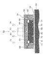
図3は、ウェーハ研磨装置50の一例を示す要部断面図である。このウェーハ研磨装置50は、回転する研磨定盤52の表面に研磨布54が貼付されている。研磨布54の上方には、ウェーハ保持ヘッド14が、ウェーハWを保持しながら回転され、ウェーハWを研磨布54に当接させるように配置されている。
FIG. 3 is a cross-sectional view of an essential part showing an example of the wafer polishing apparatus 50. In this wafer polishing apparatus 50, a polishing
ウェーハ保持ヘッド14は、ヘッド本体56、バックプレート58、リテーナリング60、保護シート62、バックプレート用エアバッグ64及びリテーナーリング用エアバッグ66等から構成されている。
The
バックプレート用エアバッグ64は、ゴムシート68とヘッド本体56とで形成される空間で、エアライン70からエアが供給され、バックプレート58を研磨布54に向けて加圧する。リテーナーリング用エアバッグ66は、ゴムシート68とヘッド本体56とで形成される空間で、バックプレート用エアバッグ64よりも外周側に設けられる。このリテーナーリング用エアバッグ66には、エアライン72からエアが供給され、リテーナリング60を研磨布12に向けて押圧する。
The
また、バックプレート58の下面には外周部にエア噴出口74、74…が形成され、中央部にはエア噴出口76、76…が形成されている。エア噴出口74、74…はメインエア噴射経路78に接続され、一方エア噴出口76、76…は、サブエア経路80及び不図示の切替バルブを介して正圧ライン及び図1の減圧ライン36に接続されている。よって、切替バルブによって減圧ライン36を開放することにより、ウェーハ保持ヘッド14によってウェーハWが減圧吸着される。
Further,
保護シート62は、周縁部がリテーナーリング60に保持されており、ウェーハWが硬いバックプレート58に直接接触することを防止し、ウェーハWに当接してバックプレート58からのエア圧をウェーハWに伝達する。バックプレート58から噴射されたエアはバックプレート58とリテーナーリング60との隙間から外部に排気される。メインエア経路78によるエアの圧力とサブエア経路80によるエアの圧力とをそれぞれ調整することによって、ウェーハWの研磨形状が制御される。
The
保護シート62にはウェーハ吸着用の吸着口(不図示)が形成されており、ウェーハWの搬送時にウェーハWを吸着保持するために使用される。すなわち、ウェーハWの吸着時は、切替バルブによってサブエア経路80が減圧ライン36に切り替えられ、複数の吸着口を経由してウェーハWに吸引力が伝達される。
The
ウェーハ保持ヘッド14は以上のように構成され、このウェーハ保持ヘッド14によって保持されたウェーハWが研磨定盤52上の研磨布54に押し付けられ、研磨定盤52とウェーハ保持ヘッド14とがそれぞれ回転されながら、研磨布54上にスラリを供給することにより、ウェーハWが研磨される。
The
一方、図1に示す第1のドレインタンク16は、減圧ライン36と減圧ライン38との間に設置され、その内部は常時真空に維持されている。したがって、第1のドレインタンク16に、ウェーハ保持ヘッド14によって吸い込まれた排液が減圧ライン36を介して溜められる。
On the other hand, the
第1のドレインタンク16には、水位センサー18が取り付けられている。この水位センサー18は、第1のドレインタンク16に溜められた排液の液面を検出するセンサーであり、第1のドレインタンク16において排液が十分に溜まったことを検出する高さ位置に取り付けられている。水位センサー18によって排液の液面を検出したことを示す信号は、図2に示したCPU34に出力され、CPU34はこの信号に基づき第1乃至第4のバルブ22、24、26、30の開閉を制御する。
A
第1のバルブ22は、第1のドレインタンク16に溜まった排液を第2のドレインタンク20に排出するためのバルブであり、第2のバルブ24は、第2のドレインタンク20を大気開放させるためのバルブである。また、第3のバルブ30は、第2のドレインタンク20に溜まった排液を外部に排水するためのバルブであり、第4のバルブ26は、開放されることによりバッファタンク32の真空によって第2のドレインタンク20を減圧させるためのバルブである。
The
ここで、第1のドレインタンク16と第2のドレインタンク20を一つのドレインタンクAとして、この間部をゲート弁などの遮蔽板で仕切ることにより二つの部屋に分割し、同様のシーケンスで排水する場合も本発明の内容と本質的に変わらない。
Here, the
バッファタンク32は、減圧ポンプ12に接続されて真空に保持されるとともに、第2のドレインタンク20に連結ライン82を介して接続されている。この連結ライン82に、第2のバルブ24と第4のバルブ26からなる三方弁28が取り付けられている。なお、バッファタンク32は、第2のドレインタンク20を瞬時に真空状態下に復帰させるため、第2のドレインタンク20の容積よりも圧倒的に大容量のものが使用されている。例えば、第2のドレインタンクの容量500mlに対し、30lの容量のものが使用されている。
The
次に、図3に示したCPU34によるワーク吸着装置10の制御方法について説明する。
Next, the control method of the workpiece | work adsorption |
CPU34は、ウェーハ保持ヘッド14によるウェーハWの吸着時において真空状態の第1のドレインタンク16に取り付けた水位センサー18から排液排水情報(第1のドレインタンク16に排液が十分に溜まったことを示す情報)が出力されると、又は所定の時間が経過すると、まず、第1のバルブ22を開放させて第1のドレインタンク16に溜められた排液を、同じく真空状態の第2のドレインタンク20に排出する。次に、CPU34は、第1のバルブ22を閉鎖して第1のドレインタンク16と第2のドレインタンク20とを遮断する。次いで、CPU34は、第2のバルブ24を開放させて第2のドレインタンク20のみを大気開放させるとともに、第3のバルブ30を開放させて第2のドレインタンク20に溜められた排液を外部に排水する。そして、CPU34は、第3のバルブ30を閉鎖させて第2のドレインタンク20を密閉し、第4のバルブ26を開放させることにより第2のドレインタンク20を、バッファタンク32の真空により減圧させる。これにより、排液が実際に溜まる第1のドレインタンク16は、常時真空状態下にあるので、ウェーハ保持ヘッド14によるウェーハWの吸着時における排液排水が可能になり、また、上述の如くCPU34によって第1乃至第4のバルブ22、24、26、30の開閉を制御することによって、排液排水処理を人手によらず自動化することが可能になる。
The
図4は、図3に示したCPU34による第1乃至第4のバルブ22、24、26、30の開閉動作の一例を示したタイミングチャートである。
FIG. 4 is a timing chart showing an example of opening and closing operations of the first to
図4によれば、まず、電源ON時の時刻t1において、第1のバルブ22及び第3のバルブ30が閉鎖され、また、三方弁28の第2のバルブ24が開放されるとともに第4のバルブ26が閉鎖されて大気開放側に設定されている。次に、イニシャル開始時の時刻t2において、第3のバルブ30のみ開放され、この状態がイニシャル終了時の時刻t3まで継続される。次いで、イニシャル終了時の時刻t3において、第3のバルブ30が閉鎖され、これと同時に三方弁28の第2のバルブ24が閉鎖されるとともに第4のバルブ26が開放されて真空側に設定変更される。これにより、図1に示した第2のドレインタンク20は、バッファタンク32の真空により減圧され、瞬時に真空状態下になる。
According to FIG. 4, first, at time t1 when the power is turned on, the
この後、図4の如く時刻t4になると、第1のバルブ22が開放され、この状態が時刻t5まで継続され、時刻t5になると第1のバルブ22が閉鎖される。ここで、時刻t3〜t4までの所要時間aが、「切替時間」であり、排液排水のために大気開放された第2のドレインタンク20の真空度が規定値まで上昇する時間である。この所要時間a中にウェーハ保持ヘッド14により吸い込まれた排液が第1のドレインタンク16に溜められる。また、時刻t4〜t5までの所要時間bが、「動作時間」であり、真空により吸い込まれた排液を第1のドレインタンク16から第2のドレインタンク20に溜める時間である。
Thereafter, at time t4 as shown in FIG. 4, the
この後、時刻t6になると、第3のバルブ30が開放され、また、三方弁28の第2のバルブ24が開放されるとともに第4のバルブ26が閉鎖されて大気開放側に設定される。この状態は、時刻t7まで継続される。これにより、第2のドレインタンク20は大気開放され、第3のバルブ30も開放されるので、第2のドレインタンク20に溜められた排液が第2のドレインタンク20から外部に排水される。なお、この時、第1のバルブ22は閉鎖されているので、第1のドレインタンク16は真空状態に維持され、ウェーハ保持ヘッド14によって吸い込まれた排液が継続して溜められている。ここで、時刻t5〜t6までの所要時間cが、「排水前時間」であり、排液排水前の準備として、大気開放する前に第1のバルブ22を先行して閉鎖しておくために要する時間である。また、時刻t6〜t7までの所要時間dが、「排水時間」であり、第2のドレインタンク20に溜まった排液を排水する時間である。このように、CPU34は、時刻t3〜t7までの時間内において、a、b、c、dの各所要時間を1サイクルとして第1乃至第4のバルブ22、24、26、30の開閉タイミングを制御することにより、ウェーハ保持ヘッド14によるウェーハ搬送中の排液排水処理が可能になり、また、排液排水処理を自動化できる。
Thereafter, at time t6, the
なお、バルブ26及びバルブ26とバッファタンク32とを連結するラインLは、第2のドレインタンク20の容積が十分に小さく、第1のドレインタンク16の真空圧に影響しない場合には、必要としない場合がある。
The line L connecting the
図5は、他の実施の形態のワーク吸着装置100の構成を示した図である。同図に示すワーク吸着装置100は、減圧ポンプ102、ウェーハ保持ヘッド(減圧吸着機構)104、第1のドレインタンク106、第1の水位センサー108、第2のドレインタンク110、第2の水位センサー112、切替バルブ114、第1のバルブ116と第5のバルブ118とからなる三方弁120、第3のバルブ122、第2のバルブ124と第6のバルブ126とからなる三方弁128、第4のバルブ130、バッファタンク(緩衝タンク)132、及び図6に示すCPU(制御部)134を主として構成されている。
FIG. 5 is a diagram illustrating a configuration of a
ウェーハ保持ヘッド104は、減圧ポンプ102に減圧ライン136、138、140、142を介して接続され、このウェーハ保持ヘッド104にウェーハWが減圧吸着されて所定の位置に搬送される。なお、ウェーハ保持ヘッド104と図3に示したウェーハ保持ヘッド14と同一構造なので、ここではウェーハ保持ヘッド104の詳細な説明を省略する。
The
図5に示す第1のドレインタンク106は、減圧ライン136と減圧ライン138との間に設置され、その内部は常時真空に維持されている。したがって、第1のドレインタンク106に、ウェーハ保持ヘッド104によって吸い込まれた排液が減圧ライン136を介して溜められる。
The
また、減圧ライン136には切替バルブ114が設けられており、この切替バルブ114の切り替え動作によって、減圧ライン136の経路が第1のドレインタンク106側に、又は第2のドレインタンク110側に切り替えられる。
Further, the switching
第1のドレインタンク106には、水位センサー108が取り付けられている。この水位センサー108は、第1のドレインタンク106に溜められた排液の液面を検出するセンサーであり、第1のドレインタンク106において排液が十分に溜まったことを検出する高さ位置に取り付けられている。また、同様に第2のドレインタンク110にも、水位センサー112が取り付けられている。この水位センサー112は、第2のドレインタンク110に溜められた排液の液面を検出するセンサーであり、第2のドレインタンク110において排液が十分に溜まったことを検出する高さ位置に取り付けられている。水位センサー108、112によって排液の液面を検出したことを示す信号は、図6に示したCPU134に出力され、CPU134はこの信号に基づき切替バルブ114、第1乃至第6のバルブ116、118、122、124、126、130の開閉を制御する。
A
第1のバルブ116は、第1のドレインタンク106を大気開放させるためのバルブであり、また、第2のバルブ124は、第2のドレインタンク110を大気開放させるためのバルブである。更に、第3のバルブ122は、第1のドレインタンク106に溜まった排液を外部に排水するためのバルブであり、第4のバルブ130は、第2のドレインタンク110に溜まった排液を外部に排水するためのバルブである。更にまた、第5のバルブ118は、開放されることによりバッファタンク132の真空によって第1のドレインタンク106を減圧させるバルブであり、第6のバルブ126は、開放されることによりバッファタンク132の真空によって第2のドレインタンク110を減圧させるバルブである。
The
バッファタンク132は、減圧ポンプ102に接続されて真空に保持されるとともに、第1のドレインタンク106に減圧ライン138を介して接続されるとともに、第2のドレインタンク110に減圧ライン140を介して接続されている。この減圧ライン138に、第1のバルブ116と第5のバルブ118からなる三方弁120が取り付けられ、減圧ライン140に、第2のバルブ124と第6のバルブ126からなる三方弁128が取り付けられている。なお、バッファタンク132は、第1及び第2のドレインタンク106、110を瞬時に真空状態下に復帰させるため、第1のドレインタンク106及び第2のドレインタンク110の容積よりも圧倒的に大容量のものが使用されている。例えば、第2のドレインタンクの容量500mlに対し、30lの容量のものが使用されている。
The
次に、図6に示したCPU134によるワーク吸着装置100の制御方法について説明する。
Next, the control method of the workpiece | work adsorption |
CPU134は、ウェーハ保持ヘッド104によるウェーハWの吸着時において、排液が溜められている真空状態下の第1のドレインタンク106の第1の水位センサー108から排液排水情報が出力されると、又はCPU134がタイマによって時間管理している場合には所定の時間が経過すると、まず、切替バルブ114によって第2のドレインタンク110側がウェーハ保持ヘッド104と連通するように切り替える。これにより、第1のドレインタンク106がウェーハ保持ヘッド104と遮断される。
When the drainage / drainage information is output from the first
そしてCPU134は、第1のバルブ116を開放させて第1のドレインタンク106を大気開放させ、この後に第3のバルブ122を開放させて第1のドレインタンク106に溜まった排液を外部に排水する。
Then, the
次にCPU134は、第1のバルブ116と第3のバルブ122とを閉鎖させるとともに、第5のバルブ118を開放させてバッファタンク132の真空により第1のドレインタンク106を減圧させて真空状態下に素早く復帰させる。
Next, the
次いでCPU134は、排液が溜められている第2のドレインタンク110の第2の水位センサー112から排液排水情報が出力されると、又はCPU134がタイマによって時間管理している場合には所定の時間が経過すると、まず、切替バルブ114によって第1のドレインタンク106側がウェーハ保持ヘッド104と連通するように切り替える。これにより、第2のドレインタンク110がウェーハ保持ヘッド104と遮断される。
Next, when the drainage / drainage information is output from the second
そしてCPU134は、第2のバルブ124を開放させて第2のドレインタンク110を大気開放させ、この後に第4のバルブ130を開放させて第2のドレインタンク110に溜まった排液を外部に排水する。
Then, the
次にCPU134は、第2のバルブ124と第4のバルブ130とを閉鎖させるとともに、第6のバルブ126を開放させてバッファタンク132の真空により第2のドレインタンク110を減圧させ、真空状態下に素早く復帰させる。
Next, the
これにより、排液が実際に溜まる第1のドレインタンク106及び第2のドレインタンク110のうち少なくとも一つのドレインタンクは、常時真空状態下にあるので、ウェーハの搬送中における排液排水が可能になり、また、上述の如くCPU34によって切替バルブ114、第1乃至第6のバルブ116、118、122、124、126、130の開閉を制御することによって、排液排水処理を自動化することが可能になる。
Accordingly, at least one of the
なお、図1及び図5の例において、減圧ポンプ12、102を使用したが、排気速度の大きい減圧ポンプを使用する場合は、バッファタンクはなくてもよい。よって、バッファタンクのない場合には、第5バルブ及び第6バルブは存在せず、CPU134は、第5バルブ及び第6バルブ以外のバルブを開閉制御する。
1 and 5, the
10、100…ワーク吸着装置、12、102…減圧ポンプ、14、104…ウェーハ保持ヘッド、16、106…第1のドレインタンク、18、108…水位センサー、20、110…第2のドレインタンク、22、116…第1のバルブ、24、124…第2のバルブ、26、130…第4のバルブ、30、122…第3のバルブ、32…バッファタンク、34、134…CPU、118…第5のバルブ、126…第6のバルブ DESCRIPTION OF SYMBOLS 10,100 ... Work adsorption | suction apparatus, 12, 102 ... Decompression pump, 14, 104 ... Wafer holding head, 16, 106 ... First drain tank, 18, 108 ... Water level sensor, 20, 110 ... Second drain tank, 22, 116 ... first valve, 24, 124 ... second valve, 26, 130 ... fourth valve, 30, 122 ... third valve, 32 ... buffer tank, 34, 134 ... CPU, 118 ... first 5 valves, 126 ... sixth valve
Claims (13)
前記減圧ラインに取り付けられることにより真空に保持され、前記減圧吸着機構によって吸い込まれた排液が減圧ラインを介して捕集される第1のドレインタンクと、
前記第1のドレインタンクに連通された第2のドレインタンクと、
前記第1のドレインタンクに溜まった前記排液を前記第2のドレインタンクに排出するための第1のバルブと、
前記第2のドレインタンクを大気開放させる第2のバルブと、
前記第2のドレインタンクに溜まった排液を外部に排水するための第3のバルブと、
前記減圧ラインに接続されて真空に保持されるとともに、前記第2のドレインタンクに連結ラインを介して接続された緩衝タンクと、
前記連結ラインに設けられるとともに、開放されることにより前記緩衝タンクの真空によって第2のドレインタンクを減圧させる第4のバルブと、
を備えたことを特徴とするワーク吸着装置。 A vacuum suction mechanism that is connected via a vacuum line and vacuum-sucks a workpiece to be processed;
A first drain tank that is held in a vacuum by being attached to the decompression line and that collects the drained liquid sucked by the decompression adsorption mechanism via the decompression line;
A second drain tank communicated with the first drain tank;
A first valve for discharging the drainage liquid accumulated in the first drain tank to the second drain tank;
A second valve for opening the second drain tank to the atmosphere;
A third valve for draining the waste liquid accumulated in the second drain tank to the outside;
A buffer tank connected to the decompression line and held in vacuum, and connected to the second drain tank via a connection line;
A fourth valve that is provided in the connection line and is opened to depressurize the second drain tank by the vacuum of the buffer tank;
A workpiece suction device characterized by comprising:
前記減圧ラインに配置され、前記減圧吸着機構によって吸い込まれた排液が前記減圧ラインを介して捕集される第1のドレインタンク及び第2のドレインタンクと、
前記第1のドレインタンク及び前記第2のドレインタンクを、前記減圧吸着機構に交互に連通させる切替バルブと、
前記第1のドレインタンクを大気開放させる第1のバルブと、
前記第2のドレインタンクを大気開放させる第2のバルブと、
前記第1のドレインタンクに溜まった排液を外部に排水するための第3のバルブと、
前記第2のドレインタンクに溜まった排液を外部に排水するための第4のバルブと、
前記減圧ラインに接続されて真空に保持された緩衝タンクと、
前記緩衝タンクと前記第1のドレインタンクとの間の前記減圧ラインに設けられるとともに、開放されることにより前記緩衝タンクの真空によって第1のドレインタンクを減圧させる第5のバルブと、
前記緩衝タンクと前記第2のドレインタンクとの間の前記減圧ラインに設けられるとともに、開放されることにより前記緩衝タンクの真空によって第2のドレインタンクを減圧させる第6のバルブと、
を備えたことを特徴とするワーク吸着装置。 A vacuum suction mechanism that is connected via a vacuum line and vacuum-sucks a workpiece to be processed;
A first drain tank and a second drain tank, which are disposed in the decompression line and in which drained liquid sucked by the decompression adsorption mechanism is collected via the decompression line;
A switching valve for alternately communicating the first drain tank and the second drain tank to the reduced pressure adsorption mechanism;
A first valve for opening the first drain tank to the atmosphere;
A second valve for opening the second drain tank to the atmosphere;
A third valve for draining the waste liquid accumulated in the first drain tank to the outside;
A fourth valve for draining the drainage liquid accumulated in the second drain tank to the outside;
A buffer tank connected to the vacuum line and held in vacuum;
A fifth valve provided in the decompression line between the buffer tank and the first drain tank and opened to decompress the first drain tank by a vacuum of the buffer tank;
A sixth valve provided in the decompression line between the buffer tank and the second drain tank and opened to decompress the second drain tank by a vacuum of the buffer tank;
A workpiece suction device characterized by comprising:
次いで、排液が溜められている前記第2のドレインタンクの前記第2の水位検出手段から排液排水情報が出力されると、まず、前記切替バルブによって前記第1のドレインタンク側が前記減圧吸着機構と連通するように切り替えるとともに、前記第2のバルブを開放させて第2のドレインタンクを大気開放させた後に前記第4のバルブを開放させて第2のドレインタンクに溜まった排液を排水し、次に、第2のバルブと第4のバルブとを閉鎖させるとともに前記第6のバルブを開放させて前記緩衝タンクの真空により第2のドレインタンクを減圧させるように第1のバルブ、第2のバルブ、第3のバルブ、第4のバルブ、第5のバルブ、及び第6のバルブの開閉動作をそれぞれ制御することを特徴とする請求項10に記載のワーク吸着装置。 When the drainage drainage information is output from the first water level detection means of the first drain tank in which drainage is stored, the control unit first controls the second drain tank side by the switching valve. In addition to switching to communicate with the reduced pressure adsorption mechanism, the first valve is opened to release the first drain tank to the atmosphere, and then the third valve is opened to collect the waste accumulated in the first drain tank. Draining the liquid, then closing the first valve and the third valve and opening the fifth valve to depressurize the first drain tank by the vacuum of the buffer tank;
Next, when drainage drainage information is output from the second water level detection means of the second drain tank in which drainage is stored, first, the first drain tank side is decompressed and adsorbed by the switching valve. In addition to switching to communicate with the mechanism, the second valve is opened to open the second drain tank to the atmosphere, and then the fourth valve is opened to drain the waste liquid accumulated in the second drain tank. Then, the second valve and the fourth valve are closed, the sixth valve is opened, and the second drain tank is depressurized by the vacuum of the buffer tank. The work suction device according to claim 10, wherein the opening / closing operation of each of the second valve, the third valve, the fourth valve, the fifth valve, and the sixth valve is controlled.
次いで、所定の時間が経過すると、まず、前記切替バルブによって前記第1のドレインタンク側が前記減圧吸着機構と連通するように切り替えるとともに、前記第2のバルブを開放させて第2のドレインタンクを大気開放させた後に前記第4のバルブを開放させて第2のドレインタンクに溜まった排液を排水し、次に、第2のバルブと第4のバルブとを閉鎖させるとともに前記第6のバルブを開放させて前記緩衝タンクの真空により第2のドレインタンクを減圧させるように第1のバルブ、第2のバルブ、第3のバルブ、第4のバルブ、第5のバルブ、及び第6のバルブの開閉動作をそれぞれ制御することを特徴とする請求項11に記載のワーク吸着装置。 When a predetermined time elapses, the control unit first switches the second drain tank side to communicate with the reduced pressure adsorption mechanism by the switching valve, and opens the first valve to open the first drain. After the tank is opened to the atmosphere, the third valve is opened to drain the drainage liquid accumulated in the first drain tank. Next, the first valve and the third valve are closed and the fifth valve is closed. And the first drain tank is depressurized by the vacuum of the buffer tank.
Next, when a predetermined time elapses, first, the switching valve is switched so that the first drain tank side communicates with the reduced pressure adsorption mechanism, and the second valve is opened to bring the second drain tank into the atmosphere. After the opening, the fourth valve is opened to drain the drainage liquid accumulated in the second drain tank, and then the second valve and the fourth valve are closed and the sixth valve is opened. The first valve, the second valve, the third valve, the fourth valve, the fifth valve, and the sixth valve are opened so that the second drain tank is depressurized by the vacuum of the buffer tank. The workpiece suction device according to claim 11, wherein each of the opening and closing operations is controlled.
Priority Applications (1)
| Application Number | Priority Date | Filing Date | Title |
|---|---|---|---|
| JP2004233389A JP4446246B2 (en) | 2004-08-10 | 2004-08-10 | Work suction device |
Applications Claiming Priority (1)
| Application Number | Priority Date | Filing Date | Title |
|---|---|---|---|
| JP2004233389A JP4446246B2 (en) | 2004-08-10 | 2004-08-10 | Work suction device |
Publications (2)
| Publication Number | Publication Date |
|---|---|
| JP2006051556A JP2006051556A (en) | 2006-02-23 |
| JP4446246B2 true JP4446246B2 (en) | 2010-04-07 |
Family
ID=36029339
Family Applications (1)
| Application Number | Title | Priority Date | Filing Date |
|---|---|---|---|
| JP2004233389A Expired - Fee Related JP4446246B2 (en) | 2004-08-10 | 2004-08-10 | Work suction device |
Country Status (1)
| Country | Link |
|---|---|
| JP (1) | JP4446246B2 (en) |
Cited By (2)
| Publication number | Priority date | Publication date | Assignee | Title |
|---|---|---|---|---|
| WO2024228605A1 (en) * | 2023-05-03 | 2024-11-07 | 주식회사 디엔솔루션즈 | Vacuum adsorption device |
| WO2025258954A1 (en) * | 2024-06-11 | 2025-12-18 | 주식회사 디엔솔루션즈 | Vacuum suction device |
Families Citing this family (6)
| Publication number | Priority date | Publication date | Assignee | Title |
|---|---|---|---|---|
| JP6190286B2 (en) * | 2014-02-14 | 2017-08-30 | 株式会社荏原製作所 | Substrate holding device and polishing device |
| JP6810584B2 (en) * | 2016-11-30 | 2021-01-06 | タツモ株式会社 | Laminating device |
| JP6907849B2 (en) * | 2017-09-15 | 2021-07-21 | 日本電気硝子株式会社 | Glass plate manufacturing method and manufacturing equipment |
| CN109048662B (en) * | 2018-11-10 | 2024-03-15 | 宇晶机器(长沙)有限公司 | Vacuum adsorption pipeline system of continuous multi-station polishing machine |
| KR102494805B1 (en) * | 2020-08-13 | 2023-02-06 | (주)피엔피 | Ultra Thin Glass Delamination Device |
| JP2024011635A (en) * | 2022-07-15 | 2024-01-25 | 株式会社ディスコ | Gas-liquid separation equipment and processing equipment |
-
2004
- 2004-08-10 JP JP2004233389A patent/JP4446246B2/en not_active Expired - Fee Related
Cited By (2)
| Publication number | Priority date | Publication date | Assignee | Title |
|---|---|---|---|---|
| WO2024228605A1 (en) * | 2023-05-03 | 2024-11-07 | 주식회사 디엔솔루션즈 | Vacuum adsorption device |
| WO2025258954A1 (en) * | 2024-06-11 | 2025-12-18 | 주식회사 디엔솔루션즈 | Vacuum suction device |
Also Published As
| Publication number | Publication date |
|---|---|
| JP2006051556A (en) | 2006-02-23 |
Similar Documents
| Publication | Publication Date | Title |
|---|---|---|
| US10562076B2 (en) | Substrate cleaning apparatus, substrate cleaning method, and substrate processing apparatus | |
| JP4446246B2 (en) | Work suction device | |
| JP6654457B2 (en) | Drainage system for substrate processing device, drainage method, drainage control device, and recording medium | |
| JPH11320406A (en) | Method and device for treating drainage and exhaust gas from polishing device | |
| JPH10135316A (en) | Vacuum suction method for thin plate substrate and vacuum suction table device thereof | |
| JP6535649B2 (en) | Substrate processing apparatus, discharge method and program | |
| JP2008294233A (en) | Cleaning device | |
| JP6027454B2 (en) | Polishing equipment | |
| US20030127116A1 (en) | Resist stripping method and apparatus | |
| JP2001313278A (en) | Apparatus for polishing and finally cleaning semiconductor wafer | |
| JP2003324140A (en) | Wafer suction device | |
| JP2019214082A (en) | Cmp device and method | |
| KR100620162B1 (en) | Conditioner Cleaning Station for CPM Equipment | |
| JP2004319903A (en) | Vacuum line water separator, vacuum line water separation method, polishing apparatus using vacuum line water separator, and device manufacturing method using this polishing apparatus | |
| JP2976862B2 (en) | Polishing equipment | |
| KR100406476B1 (en) | Cleaning water separator for CMP equipment | |
| JP4265306B2 (en) | Wafer delivery device | |
| JP2014229828A (en) | Wafer polishing apparatus | |
| JP2009212119A (en) | Substrate treatment device | |
| KR100526920B1 (en) | Apparaus and method for chemically and mechanically polishing wafer | |
| KR100583645B1 (en) | Vacuum Mechanism for Wafer Transporter | |
| JP3426866B2 (en) | Apparatus and method for manufacturing semiconductor device | |
| JP2013000632A (en) | Sand pumping device, and sand pumping method | |
| KR20010025869A (en) | Chemical mechanical polishing apparatus | |
| KR100557463B1 (en) | Communication control method in semiconductor processing apparatus |
Legal Events
| Date | Code | Title | Description |
|---|---|---|---|
| A621 | Written request for application examination |
Free format text: JAPANESE INTERMEDIATE CODE: A621 Effective date: 20060627 |
|
| A131 | Notification of reasons for refusal |
Free format text: JAPANESE INTERMEDIATE CODE: A131 Effective date: 20090828 |
|
| A521 | Request for written amendment filed |
Free format text: JAPANESE INTERMEDIATE CODE: A523 Effective date: 20091016 |
|
| TRDD | Decision of grant or rejection written | ||
| A01 | Written decision to grant a patent or to grant a registration (utility model) |
Free format text: JAPANESE INTERMEDIATE CODE: A01 Effective date: 20091225 |
|
| A01 | Written decision to grant a patent or to grant a registration (utility model) |
Free format text: JAPANESE INTERMEDIATE CODE: A01 |
|
| A61 | First payment of annual fees (during grant procedure) |
Free format text: JAPANESE INTERMEDIATE CODE: A61 Effective date: 20100107 |
|
| FPAY | Renewal fee payment (event date is renewal date of database) |
Free format text: PAYMENT UNTIL: 20130129 Year of fee payment: 3 |
|
| R150 | Certificate of patent or registration of utility model |
Ref document number: 4446246 Country of ref document: JP Free format text: JAPANESE INTERMEDIATE CODE: R150 Free format text: JAPANESE INTERMEDIATE CODE: R150 |
|
| FPAY | Renewal fee payment (event date is renewal date of database) |
Free format text: PAYMENT UNTIL: 20130129 Year of fee payment: 3 |
|
| FPAY | Renewal fee payment (event date is renewal date of database) |
Free format text: PAYMENT UNTIL: 20140129 Year of fee payment: 4 |
|
| R250 | Receipt of annual fees |
Free format text: JAPANESE INTERMEDIATE CODE: R250 |
|
| R250 | Receipt of annual fees |
Free format text: JAPANESE INTERMEDIATE CODE: R250 |
|
| R250 | Receipt of annual fees |
Free format text: JAPANESE INTERMEDIATE CODE: R250 |
|
| R250 | Receipt of annual fees |
Free format text: JAPANESE INTERMEDIATE CODE: R250 |
|
| R250 | Receipt of annual fees |
Free format text: JAPANESE INTERMEDIATE CODE: R250 |
|
| R250 | Receipt of annual fees |
Free format text: JAPANESE INTERMEDIATE CODE: R250 |
|
| LAPS | Cancellation because of no payment of annual fees |